TABLE OF CONTENTS NPL NOTES ON SCREW GAUGES...1 FOREWORD...1
|
|
|
- Edgar Joseph Byrd
- 7 years ago
- Views:
Transcription
1 TABLE OF CONTENTS NPL NOTES ON SCREW GAUGES... FOREWORD... PART I: INTRODUCTION... SCOPE... DEFINITIONS...3. General definitions for screws...3. Definitions for parallel screw threads Definitions relating to taper screw threads ELEMENTS OF A SCREW THREAD AND THEIR ERRORS Pitch diameter Pitch Error in pitch in relation to pitch diameter Errors in flank angles in relation to pitch diameter Radii at crest and root Summary GAUGING PARALLEL SCREW THREADS Gauges for external threads Gauges for internal threads Length of gauge Thread form of gauge... 5 PREPARATORY FEATURES OF GAUGES Gauge blanks Hardness and stabilization Centre of plugs; end faces of rings End threading... PART II: PARALLEL SCREW THREADS CONDITIONS OF MEASUREMENT Temperature Units MECHANICAL MEASUREMENTS OF PARALLEL SCREW PLUG GAUGES Major diameter Pitch diameter Minor diameter Pitch "Drunkenness" Thread form and flank angles... 8 FORMULAE AND CORRECTIONS FOR USE IN THE MEASUREMENT OF THE PITCH DIAMETER OF PARALLEL SCREW PLUG GAUGES BY MEANS OF SMALL CYLINDERS Formula for calculating pitch diameter E of thread with symmetrical flank angles Determination of rake correction, c Correction e for the elastic compression of cylinders Consideration of rake and compression corrections Measurement of pitch diameter using cylinders other than best size Measurement of thread angle using cylinders of different sizes MECHANICAL MEASUREMENTS OF PARALLEL SCREW RING GAUGES Minor diameter Pitch diameter Displacement method Radial method Horizontal diametral comparators Pitch Thread form and angle...39

2 INSPECTION OF PARALLEL SCREW RING GAUGES WITH CHECK PLUGS...4 TESTING OF SCREW CALLIPER GAUGES...4 OPTICAL PROJECTION APPARATUS...4. Horizontal projector Examination of thread form Modern projectors Measurement of flank angles Improved protractor and throwover method of flank angle measurement...48 PART III: TAPER SCREW THREADS SCOPE DEFINITIONS FOR TAPER SCREW THREADS, SEE FIG GAUGING TAPER SCREW THREADS ON COMPONENTS MEASUREMENT OF TAPER SCREW PLUG GAUGES Elements to be measured Measurement of pitch, major, and minor diameters "Spotting off" to locate the specified plane Measurement of pitch diameter in a floating micrometer machine NPL/Matrix radial measuring machine NPL double sine bar machine Measurement of taper Floating micrometer machine Double sine bar machine Minor diameter: major diameter Measurement of pitch Thread form Flank angles INSPECTION OF TAPER SCREW RING GAUGES WITH CHECK PLUGS MECHANICAL MEASUREMENTS OF TAPER SCREW RING GAUGES Measurement of diameter Measurement of taper NPL/Matrix radial measuring machine Taper measurements with a modified internal micrometer NPL taper comparator Measurement of pitch Matrix pitch machine NPL/Matrix radial measuring machine NPL tilted gauge machine NPL laser pitch machine Thread form and flank angles TAPER SCREW THREADS NORMAL TO THE CONE...66 PART IV: APPENDICES...67 APPENDIX I...67 APPENDIX...75 APPENDIX APPENDIX APPENDIX APPENDIX APPENDIX APPENDIX APPENDIX APPENDIX...8

3 PART V: PLATES...9 Plate...9 Plate A... Plate... Plate 3... Plate Plate Plate Plate Plate Plate 9...8

4 NPL NOTES ON SCREW GAUGES Interchangeability and quality of fit of nuts, bolts, and other screwed fasteners e.g. threaded pipe joints, require precision in manufacture as monitored by screw gauges. Methods of measurement have been developed continuously at NPL over 7 years and are described in NPL Notes on Screw Gauges. Plugs and rings, parallel or taper, over a range from the BA series to inch casing for oil wells are considered. This report deals with principles as well as methods, and includes data and references which are useful to designer and inspector as well as to operator and student.

5 NPL NOTES ON SCREW GAUGES FOREWORD As a result of experience gained in testing large numbers of screw gauges during the first World War, the Metrology Division of the National Physical Laboratory published a pamphlet "Notes on Screw Gauges", to assist firms who were unfamiliar with the accuracy required in the manufacture and testing of gauges. This pamphlet has been in continuous demand since it was first published, and was reprinted and revised several times. In 95 the pamphlet was extensively rewritten and was renamed "Gauging and Measuring Screw Threads", forming the first of the series of handbooks prepared at the National Physical Laboratory under the general title of "Notes on Applied Science". Further editions followed, the latest in 96. This edition, which reverts to the original title, has been written in a time of flux. A balance has to be maintained between the commitment to the SI system of units and the need for the time being of the traditional imperial units since many measuring machines, tools and data sheets still perpetuate the traditional units. Simultaneously while there is reason and encouragement to prefer and to use the ISO metric screw thread, the traditional Whitworth, B.A., Unified, Acme and Pipe threads are still required. Also, considerable attention is focused nowadays on taper screw threaded gauges made with a precision which demands high quality measuring equipment in order to cover a wide range of size and applications. Over the years since the pamphlet was first published the emphasis in the Notes has moved from manufacture of the product screw threads to gauges, and this edition concentrates on gauges. However, the methods used for verification of gauges may apply to product screw threads. As regards format, this edition follows much of the layout used previously. Definitions, principles, and the design of measuring machines endure, and due attention has been given to these features. New machines have been referred to since the older machines, often to be found still in good service, are no longer marketed. In earlier editions much data relating to particular screw threads was supplied whereas now it is convenient to refer to British Standards for full information. Data which relates to measurement and which has been popular with inspectors and instructors has been added to and gathered in the Appendices. Over post war years there has been some progress in formulating international standards for screw threads, e.g. ISO metric and Unified. However, unification of screw gauge limits and methods of inspection have not been agreed as yet. Meanwhile, these Notes continue to summarise past and contemporary practice at the National Physical Laboratory.

6 PART I: INTRODUCTION SCOPE Interchangeable screwed parts, e.g. bolts and nuts, are produced in quantity, one part by a process in a specialising workshop; the counterpart, by a different process, often in a different workshop. The parts are usually inspected independently before acceptance by using gauges made to appropriate limits which ensure that the accepted parts will assemble within the limits for quality of fit. The range of screw threads is remarkable from BA and smaller to gauges like a inch tapered casing ring gauge; thus indicating the diversity and range of size covered by this report. An outline is given in Section 4 of the design of gauges and their use for testing acceptability of screwed parts. Tolerances on gauges are kept small in order that the gauges may act closely to the limits on the parts themselves: consequently screw gauges call for fine measurement. These Notes describe the various methods of measurement which are applied to screw gauges and which are applicable when necessary to screwed parts. There are several thread forms in use. Two common types are shown in Figs. a and b. The screw thread in Fig a is truncated at the crests and cleared at the roots whereas that in Fig. b shows crests and roots which are radiused, symmetrical and could engage at all points on the thread form. The latter is a traditional thread form; the former, where assembly concentrates on flank engagement, is gaining in preference. Examination and measurement applied to both types of thread form are described in some detail. Part I of this report deals with definitions, the elements of screw threads and the effect of their errors. The design and use of gauges for parallel screw threads is explained. A screw thread may be formed by a helical groove in a cylinder, known then as a parallel screw thread; or in a cone, known then as a taper screw thread. There are some consequential differences in measurements and these are described in Parts II and III respectively. Finally, data about thread forms in common use in the United Kingdom, and other information which is required in connection with the measurement of screws are supplied in Part IV.

7 DEFINITIONS Only those screw thread terms which are used in this report are defined; the definitions should be read in conjunction with Figs. and 3. Note: BS 658: 984, ISO Glossary of terms for Cylindrical Screw Threads supply a complete set of definitions.. General definitions for screws Thread form is the shape of one complete profile of the thread, between corresponding points at the roots of adjacent grooves in an axial plane section. Included angle is the angle between the flanks of the thread, measured in an axial plane section. Flank angles are the angles between the individual flanks and the perpendicular to the axis of the thread, measured in an axial plane section. A pitch ( p) is the distance, measured parallel to the axis, between corresponding points on adjacent thread forms in the same axial plane and on the same side of the axis. Pitch is also used to describe advance of the helix parallel to the axis with full or partial rotation of the thread. 3

8 ) Progressive error of pitch is a gradual, but not necessarily uniform, deviation of the pitch of successive threads from the nominal pitch. ) Periodic error of pitch is a cyclical pattern of departures from nominal pitch which is repeated regularly along the screw. 3) Drunkenness is a periodic variation of pitch where the cycle is of one pitch length. Lead (p n ) is the axial movement of a point following its helix one turn around the thread axis. pn = n p, where n=number of starts i.e. where there are n helices started at regular intervals round the same cylinder. Rake angle (λ) is the acute angle formed by a thread helix on the pitch cylinder and a plane perpendicular to the cylinder axis. tanλ = p n πe (multi start thread) tan λ = p πe (single start thread) where E is the pitch diameter. Definitions for parallel screw threads Major diameter is that of an imaginary cylinder (termed the major cylinder) which just embraces the crests of an external thread, or the roots of an internal thread. Minor diameter is that of an imaginary cylinder (termed the minor cylinder) which just embraces the roots of an external thread, or the crests of an internal thread. Simple pitch diameter is that of an imaginary cylinder (termed the pitch cylinder) which intersects the surface of the thread where the widths of the ridge and the groove are each equal to half a pitch. Note: Pitch diameter and effective diameter were alternative terms: simple pitch diameter has now been more widely adopted and is used exclusively throughout these Notes; either in full, or without 'simple' when there is no risk of confusion. Axis of a parallel thread is the axis of its pitch cylinder. Virtual effective diameter of a parallel thread is the simple pitch diameter of an imaginary thread of perfect pitch and flank angles, cleared at the crests and roots but having the full depth of straight flanks, which would just assemble with the actual thread over the prescribed length of engagement. Note: The virtual effective diameter exceeds the simple pitch diameter in the case of an external thread, and is less than the simple pitch diameter in the case of an internal thread, by an amount corresponding to the combined diametral effects due to any errors in the pitch and flank angles of the thread. 4

9 .3 Definitions relating to taper screw threads These are set out in Section 4 of Part III 3 ELEMENTS OF A SCREW THREAD AND THEIR ERRORS Figs. a, b, and 3 indicate seven elements which require control in manufacture of screw threads. These elements are: major diameter pitch diameter minor diameter pitch flank angles radius at crest radius at root The last two elements appear in the Whitworth and BA thread forms, see Fig. b, but the thread form in Fig. a makes no demand for a radius at its crests, and its roots are cleared, which is a requirement of sufficiency and not of precise contour. Errors in any of the elements may affect the engagement of screwed parts or accuracy of screw gauges; pitch diameter, pitch and flank angles generally attract most attention as will be explained. The various elements and how errors may arise will now be discussed in some detail. 3. Pitch diameter The importance of accuracy of the pitch diameter of a screw thread becomes evident when it is realized that errors in this diameter determine to a large extent the amount of "play" between assembled screw threads. Insofar as the pitch diameter of an external thread is less than its upper limit, so its threads will appear to be thin and increasingly slack in assembly with an internal thread on its own low diametral limit. Conversely, if the pitch diameter of the external screw is above its upper limit then the threads are said to be thick. The reverse of these conditions applies to internal screw threads. 5

10 3. Pitch Section. defines nominal pitch or designated pitch as a length between consecutive turns of the thread. Additionally pitch is a function of the helix of the screw thread; for example, a screw thread should advance precisely a quarter of the pitch when the screw is rotated one quarter of a turn. Another way of looking at pitch is that if the outside of the pitch cylinder as in Fig. 3 were laid flat then the helix would appear as a straight line as illustrated in Fig. 4: pitch errors can be considered as departures from the inclined straight line depicted. Regarding pitch errors as positions where the flanks are situated incorrectly axially it is their mutual relative position, i.e. the cumulative pitch error, which affects the fitting together of screw threads. To illustrate this aspect consider Fig. 5a, which shows the errors in pitch, round and along, a screw. The errors are expressed with respect to a datum plane normal to the axis of the screw. Whereas there is a lengthening of pitch up to say.3 mm at region (a), at region (h) the pitch with respect to the datum is short by. mm. The cumulative error is a shortening of pitch between positions (a) and (h) of (.3 +. mm), i.e..5 mm. It will be seen also that the extremes of the plot are regions (i) and (f) between which there is a maximum cumulative pitch error of.5 mm. The maximum cumulative error in pitch, i.e. the maximum error in the axial distance between any two positions along the helix, has to be accommodated when one screwed part is to assemble with another. 6

11 An examination of a detailed record of pitch error such as in Fig. 5a supplies clues as to the possible source of errors and thus to their reduction. For instance a general lengthening or shortening of pitch may be due to changes in the material in hardening, or a reproduction of an error in the leading screw of the lathe or thread grinding machine upon which the sample was made. Errors of a periodic nature, see particularly the record in Fig. 5a, may be due to a to-and-fro axial motion when the sample was made, caused by damaged centres, or an out-of-square abutment face on the leading screw of headstock spindle, or eccentrically mounted change gear wheels. The quality of manufacture of modern thread grinding machines and screw correction lathes ensures that the pitch of screw gauges is well controlled and it is common practice to check accuracy of pitch only at consecutive pitches over the length of a screw gauge. However it is necessary not to lose sight of the possibility of local variations of thread from a true helix. To illustrate this need, if errors in pitch of a screw were suspected and they were checked only at one pitch intervals, Fig. 5b would be obtained; a more thorough examination as in Fig. 5a could be more revealing. 3.3 Error in pitch in relation to pitch diameter It is important to realize that errors in pitch, namely incorrect relative position of the flanks, act obstructively: for example an otherwise perfect external screw which has pitch error will not screw into a perfect internal screw of the same nominal size. It can be made to do so by removing metal from its flanks and thus reducing its simple pitch diameter. An alternative way of appreciating the connection between errors in pitch and pitch diameter is that pitch errors virtually increase the pitch diameter of an external screw and virtually reduce the pitch diameter of an internal screw. The virtual difference in pitch diameter equivalent to a pitch error may be determined as follows. Fig. 6 Virtual Difference is pitch diameter for pitch error Suppose the upper and lower outlines in Fig. 6 represent respectively a perfect internal screw and an otherwise perfect external screw but for having a pitch error of δ p. The two screws just assemble over a length of n pitches, and are depicted in contact with each other on flanks at only the first and last threads. The maximum displacement between the two threads, the pitch errorδp axially, can be seen as a symmetrical gap of δp / axially at each side at the centre thread, and can be expressed 7

12 equivalently as δ p cot α radially. Thus the external screw which has a simple pitch diameter smaller than that of the internal screw engages by behaving virtually δp cot α larger diametraly. The numerical values for cot α for threads in common use are as follows. Table : Pitch error and virtual effect on pitch diameter Thread form α cotα ISO metric Unified Whitworth British Association CME It will be seen that the virtual equivalent effect on pitch diameter is a multiple of pitch error, roughly two times for the commonest threads and roughly four times for Acme. For this reason of multiplied effect it is essential that pitch errors be kept as small as possible; measurements of pitch may be made to a resolution of.mm [. in] so that the threading process is checked closely. Appendix 4 in PART IV gives for screws of various forms the virtual differences in pitch diameter corresponding to errors in pitch in steps of. mm up to. mm, and of.5 in up to.5 in. 3.4 Errors in flank angles in relation to pitch diameter Fig. 7 illustrates the obstructive effect caused by errors in flank angles. The corresponding flanks of the two screws are not parallel and cannot make full flank-to-flank contact. Instead, the flanks of the lower outline offer contact only at their extremities: although the plug has a smaller simple pitch diameter than the ring, it behaves as if increased. Notice that the error of each flank angle δα, δα 8

13 makes its contribution to the increase. Expressed in another way, the simple pitch diameter of a plug screw is virtually increased by the equivalent of the sum, irrespective of sign, of the errors of the flank angles. If δ aand δ a represent the errors in the two flank angles of a screw thread, the virtual increase of pitch diameter of an external thread, (or virtual decrease, of an internal thread) is given by the following approximate expressions. Table : Flank angle errors and virtual effect on pitch diameter ISO metric Unified Whitworth British Association Acme Thread form Virtual change in pitch diameter *.9 p ( δ a + δa ).5 p ( δ a + δa ).9 p ( δ a + δa ).8 p ( δ a + δa ) δ a and δ a are errors expressed in degrees and irrespectively of sign; the virtual change will have the same unit as is used for p, pitch. Tables in Appendix 5 of Part IV enable the virtual change in pitch diameter to be read for any particular case. It should be noted that the expressions tabulated above, and the Tables in Part IV are based on maximum flank engagement. Attention will be drawn later to cases in which one of the assembling screw gauges has designedly reduced length of flank. * For ISO metric and unified threads the lengths of straight flank above and below the pitch line are unequal. For that reason positive errors in flank angles have slightly smaller virtual effects on pitch diameter of external screws and negative errors in flank angles (and vice versa for internal screws). The factors in the expressions above are the mean values corresponding to the two sets of conditions and are sufficiently accurate for practical purposes. 3.5 Radii at crest and root Errors of size of the radiused form and of its positioning can present excess metal and hence offer obstruction to assembly, and in the case of gauges, incorrect performance. This is the situation in particular of nominally symmetrical thread forms such as Whitworth and British Association. In the cases of threads such as ISO metric and Unified where the crests are truncated and the roots cleared it is important that the form at the crests does not carry excess metal and that the root clearance is adequate, yet does not reduce the specified length of straight flanks. 3.6 Summary The above account describes the elements of screws and shows that diameters, pitch, flank angles, and thread form have to be controlled. There can be interaction between the errors thus affecting the assembly and fit of screws. Although these notes are not intended to describe the manufacture of screws, it is important to stress attention to certain requirements. The thread cutting device, i.e. form grinding wheel, tap, die, or lathe tool, must provide an accurate form; a form tool must be presented square to the axis of the screw blank and with its form in a diametral section; the pitch must be under precise control. 9

14 4 GAUGING PARALLEL SCREW THREADS Threaded components intended to assemble and to be interchangeable have to be tested to ensure assembly and, equally importantly, with no more slackness of fit than the designer permits. A system of limit gauges as follows is recommended and is common practice. 4. Gauges for external threads a) A Go screw ring or calliper gauge made to the maximum permitted pitch diameter of the external thread. If the latter has a nominal thread form as in Fig. b the Go gauge should correspond with the maximum metal permitted outline of the product. b) A Not Go pitch diameter calliper gauge or screw ring made to the minimum permitted pitch diameter of the external thread. c) Go and Not Go plain calliper gauges made to the respective maximum and minimum permitted major diameters of the external thread. 4. Gauges for internal threads a) A Go screw plug gauge made to the minimum permitted pitch diameter of the internal thread. If the latter has a nominal thread form as in Fig. b, the Go gauge should correspond with the maximum metal permitted outline of the product. b) A Not Go pitch diameter screw plug gauge made to the maximum permitted pitch diameter of the internal thread. c) Go and Not Go plain plug gauges made to the respective permitted minimum and maximum minor diameters of the internal thread. 4.3 Length of gauge The Go screw gauges listed in sub-paragraphs (a) above should have a length of thread not less than the length of engagement of the components to be tested, thus ensuring that the effect of cumulative error in pitch in a component is taken into account. The Not Go pitch diameter screw gauges listed in (b) above may be limited to not more than three turns of thread. In their cases cumulative error of pitch in a component can play little part over the short length of engagement of the Not Go gauge. 4.4 Thread form of gauge Go screw gauges should be the counterpart of the maximum permitted metal outline of the thread to be gauged. Thus for Whitworth and B.A. threaded components the Go gauges will have radiused crests and roots to ensure that no part of the component outline exceeds its maximum permitted metal profile. However for American National, ISO metric and unified threads which have flat crests and clearance at the roots it is not practical to supply a flat at the roots of Go gauges. British Standards indicate the appropriate thread form for Go gauges and in each case it ensures that the full length of straight flank of the component thread is tested.

15 Not Go pitch diameter gauges concentrate on ensuring that the pitch diameter of the component is not outside the minimum metal limit. Accordingly the crests of the gauge are deliberately truncated and the roots cleared. Furthermore the Not Go gauge offers reduced flank contact with a component thread and thus is less affected by flank angle errors than it would be in full flank engagement. In conclusion it should be understood that whereas the system of gauges works well it is not a complete inspection method. It depends upon satisfactory thread form; also on minimised errors of pitch and of flank angles of component and gauge. 5 PREPARATORY FEATURES OF GAUGES It is necessary to give correct attention to certain features in making screw gauges where they affect the quality of the gauges and facilitate measurement. 5. Gauge blanks It is a common practice to grind the threads of gauges in hardened and stabilized steel blanks. Recommended designs and dimensions of gauge blanks are specified in BS44: Gauge Blanks. In the case of small ring gauges and when hardened blanks are not stocked, unhardened blanks must be threaded, hardened, stabilized and subsequently ground or lapped to form and size; in these circumstances BS44 provides guidance. In all cases the length of blank of GO gauges should be chosen to ensure that they operate over at least the length of engagement of the workpiece threads. 5. Hardness and stabilization Finished gauges, and hence the hardened blanks, should be not so hard that the threads are brittle and likely to snap off, yet hard enough to avoid bruising. Hardness values between 65 and 75 DPN are in general satisfactory. It is difficult to make hardness measurements on the flanks of screw threads by diamond pyramid indentation methods but a fairly close estimate of their hardness can readily be obtained by the use of a special scriber, without causing them any damage. Such a scriber, as used at the NPL, consists of a small round Swiss file the end of which is ground to a smooth hemisphere of about.6 mm (.5 in) radius. The tool is mounted in a wooden handle, and is used for comparing the flanks of the gauge with independent working standards of hardness, by drawing it across the face of each in turn, using as equal a pressure as possible, and by comparing the resulting marks. A reasonably heavy pressure, by the fingers bearing on the tool, should be used. Gauge makers can readily provide such standards of hardness for themselves. They may consist of flat pieces of steel of convenient size, hardened and tempered down to different degrees. Five such pieces for example, one untempered and one each tempered at C, 3 C, 4 C and 5 C, and checked in a hardness testing machine will probably be found to cover an adequate range. The steel of gauges must be stabilized, before finishing the thread. Blanks to BS 44 are supplied already stabilized. Otherwise a recommended treatment is to heat the hardened, roughed out gauges to 5 C and maintain them at this temperature for five hours followed by slow cooling. 5.3 Centre of plugs; end faces of rings

16 The centres, internal or external, supplied in a plug define the axis for manufacture and measurement, and should be well-finished cones. Large, long centres should be avoided and the mouth should be protected by a small recess in or (.8 or.5 mm) deep as shown in Fig The end faces of ring blanks should be surfaced before final threading and one of them should be finished flat and free from marking. This one should be used for a datum normal to the axis of the threading process, and for mounting for measurement. 5.4 End threading Terminal threads decrease from a section of full thread form to nothing, but in the process of running out become a sharp fin of metal which is easily damaged in shape and position, and likely to falsify the performance of a gauge. Accordingly unless instructions to the contrary are given, the length of incomplete thread shall be removed or, in the case of small rings, bevelled down to avoid damage.

17 PART II: PARALLEL SCREW THREADS 6 CONDITIONS OF MEASUREMENT 6. Temperature Measurements of diameter and pitch apply at the reference temperature of C (68 F). The machines described in this report use steel micrometer screws and hardened steel cylindrical standards for measurement by comparison. It is not essential that measurements in these circumstances be made at exactly C: it is vital however that steel gauge and steel standards are at the same temperature before and during comparison. This is usually affected by standing gauge and standard alongside, close to the measuring machine, in a situation at reasonably constant temperature near C, so that all items may reach the same temperature. 6. Units The results of measurement are expressed in millimetres or in inches to compare with the units used for the prescribed limits of size of the gauges. National transition from inches to solely metric measure is incomplete and meanwhile some measurements required in metric measure are made on inch reading machines and vice versa. This presents no problem providing a conversion factor of inch = 5.4 mm exactly is used either to convert limits or to convert results. Throughout this report both units will be used as appropriate. The text background of this report justifies a fraction as small as. inch and, in some cases,. inch. Regarding metric measure,.4 in is closely. mm which is denoted by µm, and errors will be expressed in this unit at times. 7 MECHANICAL MEASUREMENTS OF PARALLEL SCREW PLUG GAUGES 7. Major diameter A bench micrometer of NPL design as illustrated in Plate II serves for measuring the major diameter of parallel plug screw gauges. It consists of a cast iron frame on which are mounted a micrometer head with an enlarged thimble opposite a fiducial indicator; the assembly makes a calliper by which measurements are reproducible within ±. mm (±.5 in). The micrometer is used as a comparator. Thus the bench micrometer reading R B is taken on a standard cylindrical plug of known diameter B of about the same size as the major diameter to be measured. A reading R G is then taken across the crests of the gauge. Its major diameter, D, is given by D = B+ R R Further readings should be taken along and round the gauge to explore the variations in major diameter. Finally the reading R B on the standard should be checked to confirm that the original setting has not changed. It is essential, if accurate results are to be obtained, that the above instructions should be followed. 3 G B

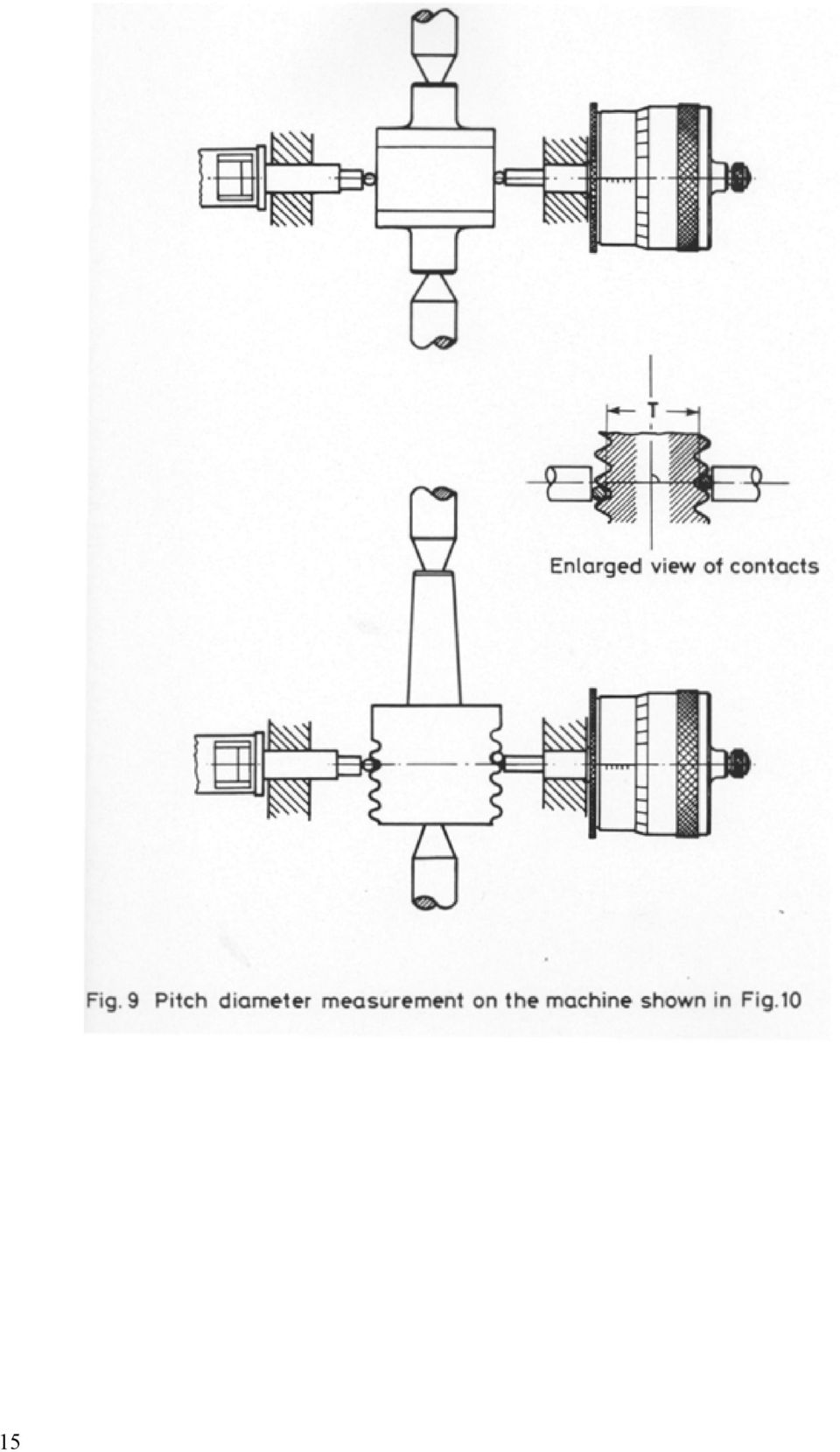
18 It is not satisfactory to attempt to establish the "zero" setting of the machine by bringing the micrometer and indicator faces into direct contact, either with or without the interposition of gauge blocks. The above procedure can be improved upon by carefully setting the bench micrometer so that R B = B, as follows: ) Set the micrometer to read B, the known diameter of the standard cylinder. ) Adjust the indicator towards the micrometer until the standard cylinder is held between the measuring faces, and the indicator pointer is approximately opposite its fixed mark. Clamp the indicator. 3) Unscrew the micrometer a turn and then screw it forward until it grips the standard, and the indicator pointer is exactly in line with its fixed mark. 4) Rotate the micrometer barrel as necessary to adjust the reading to B exactly. Subsequent readings R G of the bench micrometer on the crests of the screw gauge with the indicator pointer at the fixed mark are major diameters, i.e. RG = D. It will be seen that the stated result depends on the accepted size B of the cylindrical standard. Sets of such standards may be purchased complete with a Report giving a calibrated size at C for each item. If a bench micrometer is not available, then a hand micrometer in compliance with BS 87: Micrometers (External) may be used. It should be checked for reading R B on a cylindrical standard of known size B close to the major diameter of the screw gauge and a correction to reading deduced. A light but positive measuring force should be used, and the same force applied when contacting the crests of the gauge. Although measuring skill with the hand micrometer can be developed, nevertheless it is preferable and advantageous to use a bench micrometer as described earlier. 7. Pitch diameter The pitch diameter is best measured by taking micrometer-machine readings over a pair of small cylinders seated between the flanks on opposite sides of the plug screw gauge (see Fig. 9). The cylinders should be chosen to make contact about half-way down the flanks, i.e. close to the pitch line. The small cylinders should be cylindrical to within. mm (.4 in) and their diameters should be known to well within the same figures. Suitable cylinders for metric and other threads may be purchased in compliance with BS 559: Screw thread metric series measuring cylinders. See also Appendix 6 in Part IV. 4
 Unscrew the micrometer a turn and then screw it forward until it grips the standard, and the indicator pointer is exactly in line with its fixed mark.")
19 5
20 With this method, it is essential that the micrometer should be held at right angles to the axis of the screw gauge being measured. This is best secured by using a "floating micrometer" diameter measuring machine of the type shown in Fig.. The gauge is mounted between a pair of centres carried on a base (A) which has two vee-grooves machined in its upper surface parallel to the line of the centres. These vee-grooves form runways for a saddle (B), having on one side two projecting conical pegs (C) which rest in one of the grooves. The other end of the saddle rests on a steel ball placed in the other vee-groove. A micrometer carriage (D), with a vee-groove and a flat on its underside, can move freely on steel balls resting in two vee-grooves cut in the upper surface of the saddle in a direction at right angles to the line of centres. This micrometer carriage is provided on one side with a micrometer head graduated to either. mm or. in and capable of being read to.5 mm or. in, and on the other side with an adjustable anvil associated with a 6
, having on one side two projecting conical pegs (C) which rest in one of the grooves.")
21 sensitive indicator. The common axis of the micrometer and anvil is at the same height as the line of centres. The shank of one of the conical pegs (C) is made eccentric; so that by turning it in its hole, it is possible to adjust the axis of the micrometer truly square with the line of centres. After making this setting, the position of the peg can be maintained by a clamping screw. Taken as a whole, the machine is a development of the bench micrometer already described, having a free motion at right angles to the line of centres, and capable also of being traversed along the bed of the machine so as to measure at any desired position along a screw gauge mounted between the centres. The cylinders used with the machine during the measurements of the pitch diameter are suspended by threads from light rods (E) fixed to the micrometer carriage. In order to eliminate entirely the personal element as regards the "feel" of the micrometer, and also to obtain a control of the measuring force, the adjustable anvil is fitted with a fiducial indicator (F) which operates under a force of about 5 grams wt (8 oz wt), or less if desired. The machine described, which was designed at NPL, is obtainable commercially in two or three sizes to accommodate gauges up to 5 mm ( in) or so in diameter. Reference should now be made to Fig. 9 where the central diagram shows cylinders seated in the groove of the thread and the dimension T beneath them. The objective of the measurement in the floating micrometer machine is to determine T. The pitch diameter E is then obtained from the measured value of T by the formula: E = T + P c+ e Where P is a constant depending on the pitch and angle of the screw thread, and the mean diameter of the small cylinders used; c is a correction depending mainly upon the rake angle of the screw thread; e is a correction for the elastic compression of the cylinders. In practice the thread measuring cylinder are supplied with their measured diameter and with the P values appropriate to each combination of pitch and common thread form to which the cylinders may be applied. The values of c and e are in general relatively small for standard screw threads and the low measuring force used; however they must be taken into account as they are significant compared with tolerances for screw gauges. Formulae for calculating P, c and e are given in Section 8. Details of the measuring procedures are as follows. Select a cylindrical standard of known diameter of approximately the same size as the pitch diameter of the screw plug gauge to be measured, also a pair of thread measuring cylinders designated suitable for the pitch and thread form of the screw gauge; wipe clean the measuring faces of the machine, and its centres, and check that the transverse motion of the micrometer casting is free. Wipe clean the cylindrical standard and the pair of thread measuring cylinders. Clean the flanks of the screw plug gauge, its centres, and the centres of the standard with a toothbrush. The cylindrical standard of known diameter B is mounted on the centres of the machine and the thread measuring cylinders are suspended one on each side between the standard and the adjacent measuring face, see Fig. 9. The micrometer is fed in to contact cylinders and standard giving a reading R B. The standard is replaced by the gauge, the small cylinders put in the groove, and a reading R G obtained. Note that in contacting standard or gauge the small cylinders should be gently and slightly rocked parallel to the line of centres to ensure that there is true contact. Then and pitch diameter E is given by T = B+ R R E = B+ RG RB+ P c+ e Note that the above procedure can be improved upon by pre-adjusting the machine as described in G B 7
22 measurement of major diameter. In this case the initial reading R B on the cylindrical standard and thread measuring cylinders is adjusted to be exactly ( B + P). Subsequent readings R G across screw plug and cylinders give values of ( T + P). The pitch diameter is then given by the readings R G at various positions when the rake correction c and compression correction e have been applied thereto. Measurements by the foregoing procedure are reproducible to within. in (.3 mm). The above remarks are made in the context of gauges for standard threads. However there are multi start threads and threads where the pitch is coarse relative to the diameter, whereupon the rake correction c is relatively large. Correction to measurements of pitch diameter in such conditions is given detailed consideration in Section 8. The procedure described is based upon the use of a floating micrometer machine. Only if a suitable measuring machine is not available and a hand micrometer has to be used, then a set of three thread measuring cylinders whose individual mean diameters fall within a range of. in (.3 mm) is used. Two cylinders in grooves on one side of the gauge align one micrometer face, and the third cylinder is situated in mid face on the other side of the gauge. The method described above of firstly reading over thread measuring cylinders engaging a cylindrical standard and then over the cylinders in the threads of a screw plug should be followed. However, measurement of pitch diameter of gauges with a hand micrometer is cumbersome and cannot be recommended in comparison with the refined tolerances on screw gauges: the hand micrometer method is unsuitable for referee measurements. 7.3 Minor diameter In those gauges, e.g. Whitworth or BA, where the thread form at the root has a precise radius and is not "cleared" to avoid contact, the minor diameter is best measured by taking measurements over the outsides of a pair of vee-pieces seating in the grooves on opposite sides of the screw plug gauge (see Fig. ). The vee-pieces used consist of hardened steel prisms having an angle of about 45, with the front edge finished to a radius somewhat smaller than that of the curvature at the roots of the finest thread 8
23 which it is desired to measure. It is found useful to have such vees made in a series of different sizes, to cover the range of screws usually met. Details of suitable sizes of the vees will be found in Appendix 9 in Part IV. The details of the procedure for measuring minor diameter are similar to those described already for measuring pitch diameter, viz carefully cleaning the items, taking reading R B over the pair of prisms both contacting a cylindrical standard of known diameter B, taking readings R G over the prisms seated in the roots of the plug screw gauge, finally checking that R B still applies. Then the minor diameter, K = B + R g R b As mentioned in measuring major and pitch diameters, an improved method is to pre-set the measuring machine to R B =B when it is in contact with vee-pieces on each side of the cylindrical standard. Subsequent readings R G on the same prisms in contact with the roots of the screw gauge are then minor diameters at the particular positions. Note that the actual sizes of the vee-pieces do not require to be known, nor do they need to be equal. It is essential, however, that each vee-piece should be uniform along its length, i.e. the front measuring edge must be parallel to the back face, and both must be straight. Measurements of minor diameter using the foregoing procedure are reproducible to. in (.3 mm). 7.4 Pitch As a pitch error of say.3 mm between any two points on a plug screw gauge of uniform diameter virtually increases the pitch diameter by a multiple, i.e. to about.6 mm, see Table, there is always a need to monitor, and to restrict pitch error. To that end the measurement of errors in pitch is aimed at an accuracy well within.3 mm or. in and thus to contend with the virtual multiplied effect on pitch diameter. If the error is periodic or variable, the greatest error can only be found with certainty by taking measurements from one point to every other point on the same spiral. For screw gauges of ordinary types having a fairly fine pitch it is usual, however, to measure the pitch along a line parallel to the axis by measuring from the first thread groove to every thread groove in turn in an axial section. The screw is then rotated 8 on the centres and another test made. Misalignment in elevation of the line of centres of the gauge with the measuring axis could introduce an error by gradually climbing up the helix in one position of measurement, and by gradually descending the helix in the other measuring position at 8. The mean result eliminates the effect of misalignment. Unless the screw is "drunken", the maximum error which exists in the pitch can then be seen from the mean result and it is this maximum error which has to be used in estimating the virtual effective diameter (see Section 3.3). "Drunkenness" is a pitch error of a periodic nature and it will be referred to later, see Section The significance of pitch error was recognised early and a pitch measuring machine was designed and made at NPL. Many 6" x 9" pitch machines, as they were known, were made to NPL design by specialising firms, and widely used. The same principles were used in the modernised and improved design of a pitch measuring machine which the Coventry Gauge and Tool Co Ltd made in the 93s and which also is widely used. The main features of design are indicated in Plate III and in the following description. The 9
24 three main portions of the machine are the bed (A) carrying a micrometer screw, the sliding bar (B) carrying the micrometer nut, and the indicator and saddle (K). Screw plug gauges are held between centres (C), and a thread groove may be located by using a hardened steel stylus (P) with a rounded tip. This is made to travel in a direction parallel to the axis of the screw, riding in and out of the threads in turn. The stylus is fixed to the end of the first lever of an indicator (I). This lever is attached to the body of the indicator by crossed flexible steel strips which can both bend and twist under the action of the stylus in the thread. The indicator is clamped to the bar (B), which is supported on balls in vee grooves, and can be traversed over a range of 5 mm or inches by the micrometer (M), which usually has a pitch of either.5 mm or 4 threads per inch. The thrust of the micrometer is taken by an anvil rod in the bed casting; rotating the micrometer screw propels its nut and the bar (B). As the stylus is traversed along the screw being measured, the second lever of the indicator is deflected from side to side, and when its tip is brought repeatedly opposite a fixed fiducial mark ensures that the stylus is resting centrally in the successive threads, as in Fig.. Readings of the micrometer are taken at each point of fiducial setting, and from these the pitch errors of the screw can be obtained. Screws of longer lengths than 5 mm or in can be measured in successive lengths by moving the saddle (K) along the bar (B) and reclamping it in other positions.
25 Note: The above diagram is an illustration for explanation purposes: errors of pitch in gauges and of the measuring machine are usually smaller than those Fig. 3 depicts. The errors of pitch are plotted as shown by curves No and of Fig. 3. From the mean of these curves the cumulative pitch error over the length of the screw appears to be +.3 in (+7.5 µm). Before the real pitch error of the screw can be stated, any error present in the micrometer screw of the machine has to be allowed for. The lowest curve in Fig 3 shows the calibration curve for that portion of the micrometer screw which has been used. This curve shows that the error in the machine is such as to cause a screw of perfect pitch to appear long in pitch by. in (.5 µm) over its length. Hence the real cumulative pitch error of the screw under test is +. in (+5µm). To allow rapid measurements of the more common inch pitches to be made, a number of specially graduated dials (N in Plate III) are provided for attachment to the thimble of the 4 tpi micrometer. These dials are divided according to the whole number and fraction of a revolution of the micrometer screw necessary to move the stylus a distance equal to the nominal pitch of the screw under test. The actual errors of the successive threads are then readily obtained from a fixed dial (D) graduated to read direct to. inch, and finer by estimation. In addition to these special dials, the machine is also provided with another which is fully divided in 5 parts. This is used for measuring the pitch of screws for which the special dials are unsuitable, as for example BA and ISO metric screws. To assist in the measurement of the two last mentioned types, Tables given in Appendix 3 have been prepared, showing the nominal BA and ISO metric pitches, respectively, in inches. Of course the measurement of screws designed with metric pitches is facilitated by using a machine fitted with a metric micrometer and provided with appropriately specially graduated dials for fractional metric pitches. Each machine is provided with a set of stylus points having a graded series of radii. The stylus is selected which touches about half-way down the flanks of the thread of the screw whose pitch is to be measured, as illustrated in Fig "Drunkenness" A machine designed at the Laboratory for measuring drunkenness of screw plug gauges is illustrated in Plate IV. The principle of the machine is based on the fact that if a screw thread has a true helix, then the thread grooves on one side of it are always exactly midway between those on the opposite side in the same axial plane. On a drunken screw, the threads on one side may vary from left to right of the true mid-way position. The machine shown in Plate IV will measure this variation
26 as it is manifested at positions 8 apart; it resembles the floating micrometer diameter measuring machine, described earlier in this Section. It has the same type of base with a pair of centres for carrying the screw gauge and the same intermediate carriage (A) which is movable along the base, parallel to the line of centres. The upper carriage (B) can move freely at right angles to the line of centres and is fitted on each side with a stylus point (C). These stylus points make contact with the flanks of the thread along the pitch line. One of the points is fixed to the carriages but the opposite one is attached to an indicating mechanism, the front end of which is supported off the base of the carriage (B) on a vertical spring steel strip while the rear end rests on a vertical strut with pointed ends. Owing to the flexibility of the strip both in bending and twisting, this stylus point can move through a limited distance, not only at right-angles to the centres, but also parallel to them. Movements in the latter direction only are magnified two-fold by a simple lever system and are finally shown on an indicator. To test a screw plug gauge for drunkenness, it is first mounted between the centres of the machine and the two stylus points are inserted in the thread groove, one on each side. Dovetail slides are provided on the upper carriage for altering the diametral distance between the two points to accommodate gauges of different diameter up to 5 mm and also for off-setting the points according to the half pitch of the gauge to be tested. The gauge is then turned slowly on the centres and a to-and-fro movement of the indicator pointer during each turn of the gauge will reveal drunkenness. If the actual drunkenness error in the pitch of the helix is ±e over one turn of the helix, then the relative displacement of the moving stylus with respect to the fixed stylus will change by ±e within a revolution. As the indicating unit has X magnification the total movement of the indicator pointer from its mean position will be ±4e as the gauge is revolved between centres. In carrying out any type of test for drunkenness, the axis about which the screw thread is revolved should coincide exactly with the true axis of its pitch diameter. For example, a screw gauge which had been accurately cut with a correct helix and whose centres had subsequently become damaged or in some way out of true, would appear to be drunken if tested on these false centres. Thus it is important that prior to attributing drunkenness of pitch to a screw gauge, the accuracy of its centres should be verified. Very occasionally it is necessary to explore the accuracy of pitch of a screw gauge in detail. Then the gauge is mounted in a pitch measuring machine and measurements made as the gauge is turned through a series of precise angles. 7.5 Thread form and flank angles The quality of the thread form is most conveniently examined by optical projection methods. Flank angles may be measured at the same time. Apparatus suitable for the purpose is described in Section. Summarising, descriptions have been given above of the mechanical measurement of major, minor, and pitch diameters and of cumulative error of pitch.
The Bonelle Tool and Cutter Grinder
 The Bonelle Tool and Cutter Grinder The grinder was constructed about 1987 and exhibited at the 89th Model Engineering exhibition where it was awarded a bronze medal (see ME Vol164 No 3868 page 273). Subsequently
SCREW THREADS C H A P T E R 17
 C H A P T E R 17 SCREW THREADS Screw threads are of prime importance in machine drawing. It is a functional element used as temporary fasteners such as bolt, stud, nut and screw etc. These are constructed
Screw Thread Design. Rev. 3-4-09
 Screw Thread Design Screw Thread Fundamentals A screw thread is defined as a ridge of uniform section in the form of a helix on either the external or internal surface of a cylinder. Internal threads refer
DRAFTING MANUAL. Gears (Bevel and Hypoid) Drafting Practice
 Drafting Practice") Page 1 1.0 General This section provides the basis for uniformity in engineering gears drawings and their technical data for gears with intersecting axes (bevel gears), and nonparallel, nonintersecting
Page 1 1.0 General This section provides the basis for uniformity in engineering gears drawings and their technical data for gears with intersecting axes (bevel gears), and nonparallel, nonintersecting
Working Drawing and Assemblies. Chapter 10
 Working Drawing and Assemblies Chapter 10 Objectives 1.Define working drawings. 2. Describe how working drawings are used in industry. 3. List the major components of a complete set of working drawings.
This last dimension, the thread pitch diameter, is the most important as it is a reference from which all other thread measurements originate
 Training Objectives After watching the video and reviewing this printed material, the viewer will gain knowledge and understanding of the design and use of various thread types and how they are produced.
Removing chips is a method for producing plastic threads of small diameters and high batches, which cause frequent failures of thread punches.
 Plastic Threads Technical University of Gabrovo Yordanka Atanasova Threads in plastic products can be produced in three ways: a) by direct moulding with thread punch or die; b) by placing a threaded metal
Section. Tolerances. Aluminum Extrusion Manual. 4th Edition
 Section 8 Tolerances Aluminum Extrusion Manual 4th Edition Section 8 How straight is straight enough? How flat is flat enough? How uniform must a wall thickness be in order to be acceptable? These are
OD 1401 9 PRECISION MEASURING INSTRUMENTS
 SUBCOURSE EDITION OD 1401 9 PRECISION MEASURING INSTRUMENTS PRECISION MEASURING INSTRUMENTS SUBCOURSE OD1401 EDITION 9 Unites States Army Combined Arms Support Command Fort Lee, VA 23801-1809 5 CREDIT
RAPID DIAL TEST INDICATORS
 RAPID DIAL TEST INDICATORS The Verdict Rapid presents the dial face inclined to the workpiece surface ensuring good visual accessibility obviating parallax error. Rapids incorporate a rear swivel spigot
DMS 680. Universal length measuring system gauge inspection for»iso 9000«requirements
 DMS 680 Universal length measuring system gauge inspection for»iso 9000«requirements Universal length measuring system DMS 680 Wide range of applications For periodic inspection of gauges, reference gauges,
Sheet Metal Shearing & Bending
 Training Objective After watching the program and reviewing this printed material, the viewer will gain a knowledge and understanding of the principles and machine methods of shearing and bending sheetmetal
Lathe Milling Attachment
 Lathe Milling Attachment By L C. MASON BY CLEVERLY stacking cold-rolled flat stock together, T-slots and slide for this lathe milling attachment are made without costly machinery. In fact, only two tools,
Milling Milling milling cutter milling machines 1
 Milling Milling is a basic machining process by which a surface is generated progressively by the removal of chips from a workpiece as it is fed to a rotating cutter in a direction perpendicular to the
Schedule of Accreditation issued by United Kingdom Accreditation Service 2 Pine Trees, Chertsey Lane, Staines-upon-Thames, TW18 3HR, UK
 2 Pine Trees, Chertsey Lane, Staines-upon-Thames, TW18 3HR, UK Unit 7 Contact: Mr S C Sparks Solent Industrial Estate Tel: +44 (0)1489 790296 Hedge End Fax: +44 (0)1489 790294 Southampton E-Mail: info@southcal.co.uk
GEAROLOGY 4-1 WORMS AND WORM GEARS WORMS AND WORM GEARS
 GEAROLOGY 4-1 4 4-2 GEAROLOGY COMMON APPLICATIONS: Worm and worm gear sets are used in many, everyday products including: electrical mixers, hubometers, right Now that you have an understanding of two
OPERATING P L AYA B I L I T Y P R E C I S I O N D E S I G N
 P L AYA B I L I T Y P R E C I S I O N P E R F O R M A N C E OPERATING INSTRUCTIONS FOR: GolfWorks Loft and Lie Gauges code: HGCG/DGCG/LOLI2 4820 Jacksontown Road P.O. Box 3008 Newark, Ohio 43058-3008 Toll-Free:
It's large enough to handle most welding job shop projects, yet small enough to make it a worth while home-workshop tool
 It's large enough to handle most welding job shop projects, yet small enough to make it a worth while home-workshop tool H Craft Print Project No. 272 ERE'S a metal bender that will enable you to bend
METAL-TURNING LATHE Built from Stock Parts
 by Frank Beatty USING STANDARD PARTS and stock materials that are available almost anywhere, you can build this metalworking lathe with only a few tools. Because of simplification of the assembly in order
Pole Lathe and Shave Horse Design
 Pole Lathe and Shave Horse Design These pictures and accompanying words are Copyright Michael Hughes February 2002. They are not to be re-produced, in part or whole, without permission from the author.
Lecture slides on rolling By: Dr H N Dhakal Lecturer in Mechanical and Marine Engineering, School of Engineering, University of Plymouth
 Lecture slides on rolling By: Dr H N Dhakal Lecturer in Mechanical and Marine Engineering, School of Engineering, University of Plymouth Bulk deformation forming (rolling) Rolling is the process of reducing
RETROFITTING THE X3 MILLING MACHINE (2)
") RETROFITTING THE X3 MILLING MACHINE (2) Dick Stephen continues with the mechanical modifications. Fitting the ball screws The 12mm 2mm pitch supplied by THK ball screws are delivered with the nut fitted
RETROFITTING THE X3 MILLING MACHINE (2) Dick Stephen continues with the mechanical modifications. Fitting the ball screws The 12mm 2mm pitch supplied by THK ball screws are delivered with the nut fitted
ME 111: Engineering Drawing
 ME 111: Engineering Drawing Lecture # 14 (10/10/2011) Development of Surfaces http://www.iitg.ernet.in/arindam.dey/me111.htm http://www.iitg.ernet.in/rkbc/me111.htm http://shilloi.iitg.ernet.in/~psr/ Indian
Home"" """"> ar.cn.de.en.es.fr.id.it.ph.po.ru.sw
 Home"" """"> ar.cn.de.en.es.fr.id.it.ph.po.ru.sw Milling of Grooves, Elongated Slots and Break-throughs - Course: Techniques for machining of material. Trainees' handbook of lessons (Institut fr Berufliche
Force measurement. Forces VECTORIAL ISSUES ACTION ET RÉACTION ISOSTATISM
 Force measurement Forces VECTORIAL ISSUES In classical mechanics, a force is defined as "an action capable of modifying the quantity of movement of a material point". Therefore, a force has the attributes
Thread and End Connection
 www.swagelok.com and End Connection Identification Guide 2 Contents Introduction and End Connection Terminology.. 4 General Terminology... 5 Step-by-Step Identification Procedure for s and End Connections...
BARREL ALIGNMENT- A CRITICAL FACTOR IN REDUCING EXTRUDER WEAR
 BARREL ALIGNMENT- A CRITICAL FACTOR IN REDUCING EXTRUDER WEAR Jeff A. Myers- BARR Inc., Onsted, MI Mike Puhalla Milacron, Batavia, OH Abstract As processors increase the demand on the extruder for increased
GEOMETRY OF SINGLE POINT TURNING TOOLS
 GEOMETRY OF SINGLE POINT TURNING TOOLS LEARNING OBJECTIVES Introduction to Features of single point cutting tool. Concept of rake and clearance angle and its importance System of description of Tool geometry
Technical Data. 7. Bearing Fits. 7.1 Interference. 7.2 Calculation of interference F B LLLLLLLLL( A-54
 Technical Data 7. Bearing Fits 7.1 Interference For rolling s the rings are fixed on the or in the housing so that slip or movement does not occur between the mated surface during operation or under. This
Twist Drill Grinding Attachment By Steven Skiprat Jackson June 2009
 Twist Drill Grinding Attachment By Steven Skiprat Jackson June 2009 Part 1. About the tool Part 2. Mounting the tool Part 3. Using the tool Part 1. About the tool This little gadget while not a precision
Length, Finland, MIKES (VTT Technical Research Centre of Finland Ltd, Centre for Metrology / Mittatekniikan keskus)
") absolute mise en pratigue: mise en pratigue: absolute absolute Level or Range 633 633 nm 0.04 fm 2 95% No 1 474 474 THz 24 khz 2 95% No 1 532 532 nm 0.08 fm 2 95% No 50 563 563 THz 0.08 MHz 2 95% No 51
absolute mise en pratigue: mise en pratigue: absolute absolute Level or Range 633 633 nm 0.04 fm 2 95% No 1 474 474 THz 24 khz 2 95% No 1 532 532 nm 0.08 fm 2 95% No 50 563 563 THz 0.08 MHz 2 95% No 51
3 LEVELLING & SURVEYING
 3 LEVELLING & SURVEYING 3.1 General The primary reference at water-level recording stations is a set of stable bench-marks, installed in locations where their level should not change. Upon initial set-up
Universal Gauge Measuring System USERS MANUAL
 Universal Gauge Measuring System 2002 Chief Automotive Technologies, Inc. Chief s Limited One-Year Warranty & Liability CHIEF'S LIMITED ONE-YEAR WARRANTY & LIABILITY Chief Automotive Technologies, Inc.
SHOP NOTES METAL SHAPER FOR YOUR SHOP
 SHOP NOTES METAL SHAPER FOR YOUR SHOP A METAL SHAPER is indispensable for certain machining operations where flat surfaces must be produced within very close limits, such as machining flats on castings,
HOW TO MAKE A MOTOR BRACKET
 HOW TO MAKE A MOUNTING BRACKET FOR AN ELECTRIC MOTOR Often, brackets supplied with purchased items (e.g. electric motors or servos) are not ideally suited for fitting into our models or they are not supplied
7.3 Fit selection. Inner ring: Rotating. Outer ring: Stationary. Inner ring: Stationary. Outer ring: Rotating. Inner ring: Stationary
 7. Bearing Fits 7. Fitting For rolling s, inner and outer rings are fixed on the or in the housing so that relative movement does not occur between fitting surfaces during operation or under. This relative
Measurement of Length, Mass, Volume and Density
 Measurement of Length, Mass, Volume and Density Experimental Objective The objective of this experiment is to acquaint you with basic scientific conventions for measuring physical quantities. You will
MACHINING OPERATIONS AND MACHINE TOOLS
 MACHINING OPERATIONS AND MACHINE TOOLS 1. Turning and Related Operations 2. Drilling and Related Operations 3. Milling 4. Machining & Turning Centers 5. Other Machining Operations 6. Shape, Tolerance and
Practical Alignment Tools and Techniques
 Practical Alignment Tools and Techniques Bruce Lehmann Sr. Engineer, Thin Kerf Technologies Inc Accurate sawing requires attention to proper alignment and maintenance. Alignment is critical to modem sawmills
MEASURING TOOLS AND TECHNIQUES
 CHAPTER 2 MEASURING TOOLS AND TECHNIQUES When performing maintenance and repair tasks on catapults and arresting gear equipment, you must take accurate measurements during inspection, to determine the
5-Axis Test-Piece Influence of Machining Position
 5-Axis Test-Piece Influence of Machining Position Michael Gebhardt, Wolfgang Knapp, Konrad Wegener Institute of Machine Tools and Manufacturing (IWF), Swiss Federal Institute of Technology (ETH), Zurich,
Geometry and dimensional tolerances of engine bearings
 Geometry and dimensional tolerances of engine bearings Dr. Dmitri Kopeliovich (Research & Development Manager.) 1. Hydrodynamic lubrication Engine bearings operate mostly in the hydrodynamic regime of
MONDOATHENS BASKETBALL SET (Reference PK110)
") MONDOATHENS BASKETBALL SET (Reference PK110) DESCRIPTION The MONDOATHENS backstop unit is mainly designed for multi-sports pavilions and installations where the highest-level basketball competitions are
MONDOATHENS BASKETBALL SET (Reference PK110) DESCRIPTION The MONDOATHENS backstop unit is mainly designed for multi-sports pavilions and installations where the highest-level basketball competitions are
Speed-Mat Rectangle Cutter
 Speed-Mat Rectangle Cutter 1 Honeycomb baseboard. 2 Left hold down. 14 3 Bottom hold down. 4 4 Left / right rule. 8 5 8 5 Left / right rule pointer. 1 6 Top / bottom rule. 7 Top / bottom rule pointer.
NEW SIX-SEALS CUTTING RING. INTERNATIONAL INDUSTRIAL PATENT Nr. 864061 of the 10/03/99 FLANKS AND DOES NOT REPLACE THE STANDARD RING CURRENTLY IN USE
 B4 NEW SIX-SEALS CUTTING RING. INTERNATIONAL INDUSTRIAL PATENT Nr. 864061 of the 10/03/99 FLANKS AND DOES NOT REPLACE THE STANDARD RING CURRENTLY IN USE AVAILABLE IN CARBON AND STAINLESS STEEL 23 THEORY
CHAPTER 65 TAIL ROTOR DRIVE SYSTEM. Section Title Page
 CHAPTER 65 TAIL ROTOR DRIVE SYSTEM Section Title Page 65-00 Description........................................ 65.1 65-10 Tail Rotor Drive Fan Shaft.............................. 65.1 65-20 Tail Rotor
Milling. COPYRIGHT 2008, Seco Tools AB 1/111
 Milling 1/111 2/111 Milling A simple choice! Experts required? No Just follow some basic rules. 3/111 Face milling 4/111 Square shoulder milling 5/111 Disc milling 6/111 Copy milling 7/111 Plunge milling
Building an Off-Center Fixture for Turning Pendants
 Building an Off-Center Fixture for Turning Pendants Turning a pendant off-center with most available metal pendant chucks means that you will have a significant amount of mass off center, which will limit
Common Mechanical Engineering Terms
 Common Mechanical Engineering Terms Ball and Detent (n) A simple mechanical arrangement used to hold a moving part in a temporarily fixed position relative to another part. The ball slides within a bored
MaraMeter. Indicating Snap Gages
 - 9-2 MaraMeter. Indicating Snap Gages Overview MaraMeter. The Indicating Snap Gage is ideal for highly accurate and reliable results on cylindrical work pieces with a narrow tolerance. MaraMeter 840 F
6.6 GEAR MANUFACTURING. Introduction. Gear forming
 Valery Marinov, Manufacturing Technology Gear Manufacturing 123 6.6 GEAR MANUFACTURING Introduction Because of their capability for transmitting motion and power, gears are among the most important of
GUIDELINE FOR HAND HELD SHEAR VANE TEST
 GUIDELINE FOR HAND HELD SHEAR VANE TEST NZ GEOTECHNICAL SOCIETY INC August 2001 CONTENTS Page 1.0 Introduction 2 2.0 Background 2 3.0 Recommended Practice 3 4.0 Undrained Shear Strength 3 5.0 Particular
UNITED STATES CUTTING TOOL INSTITUTE Product Groupings for Standards Activities CUTTING TOOL PRODUCTS
 CUTTING TOOL PRODUCTS 1. BORING ISO 5609 Boring bars for indexable inserts Dimensions ISO 6261 Boring bars (tool holders with cylindrical shank) for indexable inserts Designation JIS B 4128 Boring bars
Cutting and Shearing die design Cutting die design
 Manufacturing Processes 2 Dr. Alaa Hasan Ali Cutting and Shearing die design Cutting die design A stamping die is a special, one-of-a-kind precision tool that cuts and forms sheet metal into a desired
ENGINEERING METROLOGY
 ENGINEERING METROLOGY ACADEMIC YEAR 92-93, SEMESTER ONE COORDINATE MEASURING MACHINES OPTICAL MEASUREMENT SYSTEMS; DEPARTMENT OF MECHANICAL ENGINEERING ISFAHAN UNIVERSITY OF TECHNOLOGY Coordinate Measuring
ELECTRIC FIELD LINES AND EQUIPOTENTIAL SURFACES
 ELECTRIC FIELD LINES AND EQUIPOTENTIAL SURFACES The purpose of this lab session is to experimentally investigate the relation between electric field lines of force and equipotential surfaces in two dimensions.
MEASURING MACHINES. Pratt & Whitney METROLOGY LABORATORY. Measurement Systems, Inc.
 METROLOGY LABORATORY Pratt & Whitney Measurement s, Inc. METROLOGY LABORATORY The Standard of Accuracy Pratt & Whitney Metrology Laboratory Machines are the standard of accuracy to which all other gages
Copyright 2011 Casa Software Ltd. www.casaxps.com. Centre of Mass
 Centre of Mass A central theme in mathematical modelling is that of reducing complex problems to simpler, and hopefully, equivalent problems for which mathematical analysis is possible. The concept of
Thickness Gauges. convex R 15 or R 40, flat 10 mm Ø, spherical
 Thickness Gauges Technical Data for Metric Thickness Gauges Page Model Lifting Contact points Contact points mm mm mm device standard available on request 130 K 15 0.1 10 15 no 6.35 mm Ø flat Ø flat, 130
Precision made in Europe. As per DIN 8606. The heart of a system, versatile and expandable.
 1 von 9 Precision made in Europe. As per DIN 8606. The heart of a system, versatile and expandable. Main switch with auto-start protection and emergency off. Precision lathe chuck as per DIN 6386 (Ø 100mm).
I BEAM TRACK INSTALLATION
 PDQ 0/700 FESTOON SYSTEM INSTALLATION AND MAINTENANCE INSTRUCTIONS INTRODUCTION The PDQ Festoon System was designed to run on one of three sizes of I-beams: S x., S8 x 8. and S x.. System trolleys must
Precision Vise Combinations
 Precision Vise Combinations PanaVise vises and work holding tools have hundreds of uses limited only by your imagination! Each vise allows the head to Tilt, Turn & Rotate and position your work anywhere
EXPERIMENT O-6. Michelson Interferometer. Abstract. References. Pre-Lab
 EXPERIMENT O-6 Michelson Interferometer Abstract A Michelson interferometer, constructed by the student, is used to measure the wavelength of He-Ne laser light and the index of refraction of a flat transparent
IMPORTANT DOCUMENTATION DO NOT DISCARD!
 PART NO.: 6441-263C SERIES GRT 3 JAW PARALLEL GRIPPERS INFORMATION SHEET IMPORTANT DOCUMENTATION DO NOT DISCARD! Use this information sheet to assist with gripper installation and setup. File with maintenance
HOBBING MACHINE TYPE ZFWZ 8000x40
 Inventory number 416/635 Year of production 1973 Serial number 7160 HOBBING MACHINE TYPE ZFWZ 8000x40 Application The machine is provided for milling cylindrical, helical and helix cogwheels. The tooth
VCE VET ENGINEERING STUDIES
 Victorian Certificate of Education 2013 SUPERVISOR TO ATTACH PROCESSING LABEL HERE STUDENT NUMBER Letter Figures Words VCE VET ENGINEERING STUDIES Written examination Section Wednesday 20 November 2013
Modular Locomotive System Instruction Manual for HBK8 George Body Kit
 Modular Locomotive System Instruction Manual for HBK8 George Body Kit Roundhouse Engineering Co. Ltd. Units 6-10 Churchill Business Park. Churchill Road, Wheatley. Doncaster. DN1 2TF. England. Tel. 01302
Service Bulletin Trucks Date Group No. Page
 Volvo Trucks North America, Inc. Greensboro, NC USA Replaces Service Bulletin 601 06 dated 03.98. Service Bulletin Trucks Date Group No. Page 9.2000 601 006 1(8) Wheel Alignment Steer and Drive Axles VN,
GEAROLOGY 2-1 SPUR GEARS SPUR GEARS
 GEAROLOGY 2-1 2 2-2 GEAROLOGY COMMON APPLICATIONS: Spur gears are used to Now that you ve been introduced to both Boston Gear and some of the basics of our Gearology course which we like to call Power
Technical Information
 tapping Technical Information Troubleshooting Guide 115 TAP DOES NOT START Program depth: Tap drill size: Tap sharpness: Compression stroke may use up the entire program depth. Check for tap drill size.
No. 57 Receiver Sight No. 57 SML Receiver Sight No. 66 Receiver Sight
 No. 57 Receiver Sight No. 57 SML Receiver Sight No. 66 Receiver Sight MOUNTING AND ADJUSTING MOUNTING LYMAN NO 57 RECEIVER SIGHT The No. 57 Sight is designed primarily for rifles with round receivers.
INSTRUCTIONS FOR CHAIN LINK INSTALLATION Chain Link fence & Posts Meshdirect.co.uk
 INSTRUCTIONS FOR CHAIN LINK INSTALLATION Chain Link fence & Posts Meshdirect.co.uk This guide explains how to correctly install our chain link fencing and post system. The guide provides details of the
C O N V E Y O R C O M P O N E N T S C H A I N S B E L T S B E A R I N G S
 C O N V E Y O R C O M P O N E N T S C H A I N S B E L T S B E A R I N G S January 2009 Issue 6 Valu Guide Brackets The Ultimate in Adjustability and Cost Savings Valu Guide brackets are part of a family
YUASA MILLING MACHINE ACCESSORIES & TOOLS
 97 HORIZONTAL / VERTICAL 5C COLLET INDEX 550 series 2 YEAR WARRANTY Spindle is manufactured with a taper seat in body frame. Rapid opening and closing is performed with a level collet closer with a leverage
Module 2 GEARS. Lecture 3 - INVOLUTE SPUR GEARS
 Module 2 GEARS Lecture 3 - INVOLUTE SPUR GEARS Contents 3.1 Introduction 3.2 Standard tooth systems for spur gears 3.3 Profile shifted gears 3.4 Involutometry 3.5 Design of gear blanks 3.1 INTRODUCTION
Pump Skid Fabrication for Magnetic Coupling. Rick Soltis Chief Mechanic City of Bedford
 Pump Skid Fabrication for Magnetic Coupling Rick Soltis Chief Mechanic City of Bedford Contents Magnetic Couplings What They Are, How They Work, Where They re Used Fabrication and Manufacturing of Pump
Think precision, Think HSS REAMING
 Think precision, Think HSS REAMING SUMMARY REAMING TOOLS 2 Zoom on a reamer 3 Which HSS for maximum efficiency? 4 Coatings for the best performance 5 Vocabulary 6 Choose the right design 7 Types of bevel
CAD / CAM Dr. P. V. Madhusuthan Rao Department of Mechanical Engineering Indian Institute of Technology, Delhi Lecture No. # 12 Reverse Engineering
 CAD / CAM Dr. P. V. Madhusuthan Rao Department of Mechanical Engineering Indian Institute of Technology, Delhi Lecture No. # 12 Reverse Engineering So what we will do in today s lecture is basically take
BUILD A TABLETOP LOOM
 BUILD A TABLETOP LOOM From 1" x 2" stock (actual 3/4" x 1"1/2) cut: 4 pieces 15" long 4 pieces 5"1/2 long Use the above to make 2 frames for the front and back of the loom. From 1" x 4" stock (actual 3/4"
Reflection and Refraction
 Equipment Reflection and Refraction Acrylic block set, plane-concave-convex universal mirror, cork board, cork board stand, pins, flashlight, protractor, ruler, mirror worksheet, rectangular block worksheet,
SELF-STEERING AXLE TABLE OF CONTENTS
 SELF-STEERING AXLE TABLE OF CONTENTS Section 1 - Introduction Section 2 - Pre-Installation Check List Section 3 - Ride Height Adjustments Section 4 - Suspension Mount Section 5 - Axle Mount Section 6 -
Topics. Introduction Gear schematics Types of gears Measuring gears
 Gear Measurement Topics Introduction Gear schematics Types of gears Measuring gears What is a gear? A gear is a wheel with teeth that mesh together with other gears. Gears change the : speed torque (rot.
SERIES ASM NEOPRENE/EPMD FLANGED SINGLE SPHERE CONNECTOR CONNECTORS. Pressures to 225 PSIG (15.51 barg) Temperatures to 230ºF (110ºC)
 Temperatures to 230ºF (110ºC)") APPLICATIONS Process Industry Weak Acids Alkalies Compressed Air Pulp & Paper MODELS ASM - Flanged Connection OPTIONS Control Rods Oil & Gas Water & Waste Pump suction & discharge Sea water Chemical lines
APPLICATIONS Process Industry Weak Acids Alkalies Compressed Air Pulp & Paper MODELS ASM - Flanged Connection OPTIONS Control Rods Oil & Gas Water & Waste Pump suction & discharge Sea water Chemical lines
Gate Leg Drop Leaf Table Plans
 Preparing the table top blanks: Cut and glue enough 3/4 stock to make three panels 40 long by 24 wide (they will be cut to final size at a later time). While the glue dries we will work on the legs. Preparing
Chapter 3 Installing Over-the-Post Railing on an L-Shaped Stair
 49 Chapter 3 Installing Over-the-Post Railing on an L-Shaped Stair In this chapter: The Over-the-Post Balustrade System Determining the Rail Centerline Using Rail Bolts Making a Pitch Block Laying Out
Milling & Machining Centers
 Training Objective After watching the program and reviewing this printed material, the viewer will gain knowledge and understanding of basic milling theories and procedures. In addition, the viewer will
Solid shape molding is not desired in injection molding due to following reasons.
 PLASTICS PART DESIGN and MOULDABILITY Injection molding is popular manufacturing method because of its high-speed production capability. Performance of plastics part is limited by its properties which
Sheet Metal Stamping Dies & Processes
 Training Objectives After watching the program and reviewing this printed material, the viewer will gain knowledge and understanding of the stamping process and the die systems used to form sheet metal.
Building a Small Horizontal Steam Engine
 T Building a Small Horizontal Steam Engine HE small engine described in this article was built by the writer in his spare time about an hour a day for four months and drives the machinery in a small shop.
technical guide Simple Linear Measurement Instruments
 technical guide Simple Linear Measurement Instruments Second edition February 2008 technical guide Simple Linear Measurement Instruments AS TG 1 Edition Statement Edition Amendment Date of Issue ISBN No.
Die casting Figure M2.3.1
 Die casting Die casting is a moulding process in which the molten metal is injected under high pressure and velocity into a split mould die. It is also called pressure die casting. The split mould used
Making 3D Threads in Feature Based Solid Modelers
 Making 3D Threads in Feature Based Solid Modelers THREAD BASICS Making true geometric threads in feature-based solid modelers is a fairly straightforward process and can be handled using several different
FREEBIRD THE ORIGINAL D.I.Y. ORNITHOPTER! Tools and Glue. Required Materials
 Do not try to make your ornithopter using "household materials". If you want it to fly, you have to build it right. FREEBIRD THE ORIGINAL D.I.Y. ORNITHOPTER! Wingspan: 16 inches Weight: 1/4 ounce The Ornithopter
LCWM Glossary. Mettler Toledo LCWM Glossary
 Mettler Toledo LCWM Glossary LCWM Glossary Accuracy A measure of a Scale s ability to provide a weight reading equal to the actual weight placed on the Scale. A Scale s accuracy is usually measured against
Length measuring instruments
 INTERNATIONAL OIML R 66 RECOMMENDATION Edition 1985 (E) Length measuring instruments Instruments mesureurs de longueurs OIML R 66 Edition 1985 (E) ORGANISATION INTERNATIONALE DE MÉTROLOGIE LÉGALE INTERNATIONAL
KIRÁLY TRADING KFT H-1151 Budapest Mogyoród útja 12-14 tel: 061307-3801 Email_pzoli@kiralytrading.hu. Clamps Clamping devices
 04000 Clamps Clamping devices 23000 22000 21000 20000 09000 08000 07000 06000 05000 04000 03000 02000 01000 297 04010 Adjustable straps Tempered steel 1.1191 Black oxide finish nlm 04010-101 Suitable thrust
Lapping and Polishing Basics
 Lapping and Polishing Basics Applications Laboratory Report 54 Lapping and Polishing 1.0: Introduction Lapping and polishing is a process by which material is precisely removed from a workpiece (or specimen)
KAWAI VERTICAL PIANO REGULATION MANUAL
 KAWAI VERTICAL PIANO REGULATION MANUAL Vol 1.0 2011 1 25 KAWAI MUSICAL INSTRUMENTS MFG. CO., LTD. 1 Regulation Process Index 1 Tighten Screws, Check Action, Strike Point, Hammer Blow P3 2 Keys P4 3 Travel,
DTU Animal Cart Programme
 DTU Animal Cart Programme TECHNICAL 21 RELEASE PIPE AND ROLLER DONKEY CART AXLES Development Technology Unit, Department of Engineering, University of Warwick, Coventry, CV4 7AL UK, tel: +44 (0)1203 523523