Hantek 1008 DIGITAL OSCILLOSCOPE USER S MANUAL. Hantek1008
|
|
|
- Darrell Davidson
- 7 years ago
- Views:
Transcription
1 USER S MANUAL Hantek1008

2 USER S MANUAL Hantek1008 (Version 1.0.0)

3 Hantek1008 Content General Safety Summary CHAPTER 1: Getting Started System Requirement Install Software Install Driver General Features General Check Probe Compensation Functional Check...19 Seft Calibration...21 Accessaries...22 CHAPTER 2: Operating Basics...23 The User s Interface...24 The Vertical System The Horizontal System The Trigger System Input Connectors CHAPTER 3: Understanding Function Set Ocsilloscope...37 Set Vertical System...38 Set Horizontal System...46 Set Trigger System...48 Save/Load...50 Utility Function...52 Measure Signal...55 The Display System Print...69 CHAPTER 4: Application Example Simple Measurement Capturing a Single Shot Signal The Application of The X-Y...74 Taking Cursor Measurements CHAPTER 5: Appendix Appendix A Appendix B

4 General Safety Summary Review the following safety precautions carefully before operating the device to avoid any personal injuries or damages to the device including any products connected to it. To avoid any potential hazards use the device as specified by this user s guide only. To Avoid Fire or Personal Injury. Use Proper Power Cord. Use only the power cord specified for this product and certified for the correct country of use. Connect and Disconnect Properly. Do not connect or disconnect probes or test leads while they are connected to a voltage source. Connect and Disconnect Properly. Connect the probe output to the measurement device before connecting the probe to the circuit under test. Disconnect the probe input and the probe reference lead from the circuit under test before disconnecting the probe from the measurement device. Observe All Terminal Ratings. To avoid fire or shock hazard, observe all ratings and markings on the product. Consult the product manual for further ratings information before making connections to the product. Use Proper Probe. To avoid shock hazard, use a properly rated probe for your measurement. Avoid Circuit or Wire Exposure. Do not touch exposed connections and components when power is on. Do Not Operate With Suspected Failures. If suspected damage occurs to the device, have it inspected by qualified service person before further operations. Provide Proper Ventilation. Refer to the installation instructions for proper ventilation of the device. Do Not Operate in Wet/Damp Conditions. Do Not Operate in an Explosive Atmosphere. Keep Product Surfaces Clean and Dry.

5 Hantek1008 Chapter 1 Getting Started The oscilloscope is small, compact, portable oscillo-scopes! The oscilloscope is ideal for production test, research and design and all of the applications involving analog circuits test and troubleshooting, as well as education and training. In addition to the list of general features on the next page, this chapter describes how to do the following tasks: System requirement Install software Install driver General features General check Probe compensation Function check Self calibration Accessories

6 System Requirement To run oscilloscope software, the needs of computer configuration are as follows: Minimum System Requirement Operating System Window NT/2000/XP/VISTA/Win7 Processor Upwards of 1.00G processor Memory 256M byte Disk Space 500M disk free space Screen Resolution 800 x 600 pixel Recommended Configuration Operating System Windows XP SP3 System Processor 2.4G Processor Memory 1G Byte Disk Space 80G Disk Space Screen Resolution 1024 x 768 or 1280 x 1024 pixel DPI Setting Normal Size (96DPI)

7 Hantek1008 Install Software Note: Do not connect the USB connection until the software installation is complete. 1. While in Windows, insert the installation CD into the CD-ROM drive. 2. The installation should start up automatically. Otherwise in Windows Explorer, switch to the CD-ROM drive and run Setup.exe. 3. The software Installation is started. Click 'Next' to continue.

8 4. Choose a destination directory. Click 'Next' to continue.

9 Hantek Check the setup information. Click Next to start copying files.

10 6. This Status dialog is displayed during files copying. 7. Updating Your System Configuration.

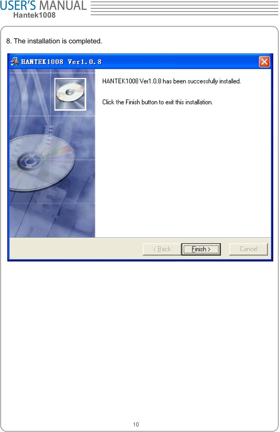
11 Hantek The installation is completed.
12 Install Driver 1. Connect the A-Type Plug of USB cable to your PC s USB port. 2. Connect the B-Type Plug of USB cable to the device's USB port. 3. New hardware is found. D

13 Hantek New hardware search wizard starts.

14 5. Select the specific location.

15 Hantek New hardware search wizard starts to search the driver.

16 7. New hardware wizard installs DRIVER. 8. The wizard has finished installation of DRIVER.

17 Hantek1008 General Feature Product features: 8 channel Maximum real-time sample rate 2.4MSa/s Max memory depth 4K points Built-in fast fourier transform function(fft) 20 Automatic measurements; Automatic cursor tracking measurements; Waveform storage, record and replay dynamic waveforms; User selectable fast offset calibration; Add, subtract, multiply and division mathematic fuctions; Adjustable waveform intensity, more effective waveform view;

18 General Check Please check the instrument as following steps after receiving the oscilloscope: Check the shipping container for damage: Keep the damaged shipping container or cushioning material until the contents of the shipment have been checked for completeness. Ensure and the instrument has been checked mechanically and electrically. Check the accessories: Accessories supplied with the instrument are listed in "Accessories" in this guide. If the contents are incomplete or damaged,please notify the franchiser. Check the instrument: In case there is any mechanical damage or defect, or the instrument does not operate properly or fail performance tests, please notify the franchiser. Probe Compensation Perform this function to match the characteristics of the probe and the channel input. This should be performed whenever attaching a probe to any input channel at the first time. From the Probe menu, select attenuation to 1:10. Set the switch to X10 on the probe and connect it to CH1 of the oscilloscope. When using the probe hook-tip, insert the tip onto the probe firmly to ensure a proper connection. Attach the probe tip to the Probe Compensator and the reference lead to the ground connector, select CH1, and then adjust the timebase and Volt/Div in sidebar. Check the shape of the displayed waveform.

19 Hantek1008 Correct Compensated Over compensated

20 Under Compensated If necessary, use the supplied non-metallic tool to adjust the trimmer capacitor of the probe for the flattest square wave being displayed on the oscilloscope. Repeat if necessary. WARNNING: To avoid electric shock while using the probe, be sure the perfection of the insulated cable, and do not touch the metallic portions of the probe head while it is connected with a voltage source. Function Check Perform this functional check to verify that your oscilloscope is operating correctly. Connect the oscilloscope You should connect the A-Type Plug of USB cable to your PC USB port and connect the B-Type Plug of USB cable to oscilloscope USB port.

21 Hantek1008 Input a signal to a channel of the oscilloscope The oscilloscope is equipped with eight channels. Please input signal in the following steps: 1. Set the attenuation switch on the probe as 10X and connect the probe on the oscilloscope with CH1. Aim the slot in the probe connector at the faucet on BNC of CH1 and insert, then, turn right to lock the probe. Finally, attach the tip of probe and ground nip to the Connector of Probe compensator. 2. Set the CH1 probe attenuation of the oscilloscope to X10. (The default is X1).
22 3. Attach the tip of probe and ground tab to the Connector of Probe compensator. Click the button. A square wave will be displayed in several seconds. (Approximately 1 khz, 2V, peak- to- peak). 4. Inspect CH2-CH8 with the same method. Repeat step 2 and 3. Self Calibration The self calibration routine lets you optimize the oscilloscope signal path for maximum measurement accuracy. You can run the routine at any time but you should always run the routine if the ambient temperature changes by 5 deg or more. For accurate calibration, power on the oscilloscope and wait twenty minutes to ensure it is warmed up. To compensate the signal path, disconnect any probes or cables from the input connectors. Then, access the Utility -> Calibration option and follow the directions on the screen. The self calibration routine takes about several minutes.
23 Hantek1008 Accessories All the accessories list below are standard accessories for the oscilloscope: Four Test Cables An Auto lgnition Probes A USB Cable A PC software of the oscilloscope
24 Chapter 2 Operating Basics The User s Interface The Menu System The Vertical System The Horizontal System The Trigger System Input Connectors
25 Hantek1008 The User s Interface Click the software icon on the desk after you finished the software installation and equipment connecting. Then a user interface will be showed as follows: In addition to displaying waveforms, the display area is filled with many details about the waveform and the oscilloscope control settings. 1. The Main Menu All settings can be found in the main menu. 2. The Toolbar 3. It shows the trigger information It shows the edge trigger slope, source and level.
26 4. It shows the main time base setting. 5. The Horizontal Panel The user can change Time/DIV, format in the panel. 6. The Vertical Panel The user can turn on/off the CH1/.../CH8. Also the user can change the CH1/.../CH8 volt/div, coupling and probe attenuation. 7. The Trigger Panel In this panel, the user can change the trigger mode, sweep, source and slope. 8. It shows the system time. 9. Marker shows edge trigger level. 10. It shows the CH1-CH8 8 information Readouts show the coupling of the channels. Readouts show the vertical scale factors of the channels. A B icon indicates that the channel is bandwidth limited. 11. The software status indicates it connected via USB. 12. The markers show the reference points of the displayed waveforms. If there is no marker, the channel is not displayed. 13. A window that shows the display waveform in buffer position. 14. Marker shows horizontal trigger position. 15. Trigger status indicates the following: AUTO: The oscilloscope is in auto mode and is acquiring waveforms even no triggers have been found. Trig D: The oscilloscope has found a trigger and is acquiring the post trigger data. WAIT: All pretrigger data has been acquired and the oscilloscope is ready to accept a trigger. STOP: The oscilloscope has stopped acquiring waveform data. RUN: The oscilloscope is running. PLAY: The oscilloscope is displaying the record waveforms.
27 Hantek1008 The Menu System The Main Menu 1. File: load or save data, setup 2. View: Change the user interface
28 3. Setup: Setup setting 4. Display: Change wave display type 5. Cursor: Set Cursor measure type 6. Measure: Set measurement parameters
29 Hantek Acquire: Run, stop or other operation setting 8. Utility: Utility setting 9. Window: Window setting
30 10. Vehicle: Vehicle setting 11. Help: Turn on help file
31 Hantek1008 The Vertical System Click Setup -> Vertical The following figure shows the vertical parameters setting in the vertical Setup window. 1. Select channel : User can select the channel by clicking the Combo Box.
32 2. ON/OFF: Turn on or off the selected channel. 3. VOLTS/DIV: Set the selected channel voltage range. 4. Coupling: DC 5. Probe: Set the Select one according to the probe attenuation factor to ensure correct vertical scale reading 6. Invert: Invert the selected wave.
33 Hantek1008 The Horizontal System Click Setup -> Horizontal The following figure shows the horizontal parameters settings in the Horizontal System window. 1. Time/DIV: lead the setting of the time base parameters 2. Format: lead the setting of the horizontal format parameters
34 The Trigger System Click Setup -> Trigger The following figure shows the trigger system control. 1. Trigger Mode: Sets the trigger mode
35 Hantek Trigger Sweep: Select the trigger sweep mode to AUTO, NORMAL or SINGLE 3. Tirgger Source: Select the trigger source to CH1-CH8. 4. Trigger Slope: Select the edge trigger slope to Positive or Negative slope
36 Input Connector CH1/.../CH8: Input connectors for waveform display. CAL: Probe compensation output. Other Connector: USB Port: Connect the B-Type Plug of USB cable to this port. Power Supply D 0 - D 7: Built in waveform generator. GND.: A ground terminal- not installed in this version.
37 Hantek1008 Chapter 3 Understanding Oscilloscope Functions Set Oscilloscope Set Vertical System Set Horizontal System Set Trigger System Save/Load Utility Function Measure Signal Print
38 Setup the Oscilloscope Save Setup The oscilloscope software saves the current setup before you close the oscilloscope software. The oscilloscope recalls this setup the next time you run the software. You can use the Save Setup menu to permanently save several different setups. Load Setup The oscilloscope can recall the last setup-any saved setups or the factory setup-before the oscilloscope software was running. You can use the Load Setup menu to permanently recall a setup. Factory Setup The oscilloscope software is set up for normal operation when it is shipped from the factory. This is the factory setup. To recall this setup, push the Factory Setup menu.
39 Hantek1008 Set Vertical System Set Channel Click Vertical in Setup Menu. The Channel Selection The Channel Control Panel in sidebar. The Vertical function: Turn ON/Off: Turn on/off the channel. Volt/DIV: Select the channel voltage/div. Coupling: DC Probe: Select the channel probe attenuation Invert: Turn on/off the invert function. Change Volt/DIV You can click Volt/DIV in Vertical Setup window to select the voltage.
40 You can also change the selected channel voltage in sidebar. You can left click and drag the mouse on the knob to change the voltage. Probe Attenuation Setting Select the attenuation factor for the probe. To check the probe attenuation setting, toggle the probe menu to match the attenuation factor of the probe. This setting remains in effect before you change again. Click Probe in Vertical Setup window to select the probe attenuation. The probe setting window in the sidebar Note: The attenuation factor x1,_- x10000 and 20:1 changes the vertical scale of the oscilloscope so that the measurement results reflect the actual voltage levels at the probe tip. The attenuation factor CC65-CC1100 is used for current measurement work with AC/DC Current Clamp.
41 Hantek1008 Invert The invert function turns the displayed waveform 180 degrees, with respect to the ground level. When the oscilloscope is triggered on the inverted signal, the trigger is also inverted. Click Invert in Vertical window The following picture shows the waveform before inversion:
42 The following picture shows the waveform of inversion:
43 Hantek1008 Set Math Click MATH in Channel menu to set MATH channel. The MATH Setup window ON/OFF: Turn On/Off the MATH Channel. Source A/B: Set the source of the math channel. Operate: Set operation type of the math channel. Volt/DIV: Set the resolution of the math channel. Probe: Set the math channel probe attenuation. Invert: Turn on/off the invert function. The mathematic functions include addition, subtract, multiply, division and FFT for CH1- CH8. Source A/B 42
44 Operate Four Types: A + B A - B A B A / B FFT Add source A and source B Subtract source B from source A Multiply source A by source B Divided source A by source B Convert a time-domain signal into its frequency components (spectrum). In this function, use the addition, subtraction, multiplication, division and FFT function to operate and analyze the waveform. Select the operate type in the Operate menu. Select source A and B. Then adjust the vertical scale and offset to view the math channel clearly. The mathematic result can be measured by the measure window and the cursor. The Math Function Display 43
45 Hantek1008 Set Reference Click REF in Setup menu to set REF channel. The Reference Channel Function: On/Off: Turn on/off the reference channel. Volt/DIV: Change the resolution of the reference channel. Load: Load the reference waveform from the.rfc file from your computer. Save: Save the current reference waveform to your computer as.rfc format. Save Reference: Save the current reference waveform to your computer as.rfc format. You can change the vertical scale of a waveform. The waveform display will zoom in or zoom out according to the reference level. Load Click Load to load the *.rfc file that was selected. And then a load file window will appear. Save 44
46 Click Save to save the waveform to *.rfc file. Then a saved source window appears. The save file window will appear after you select the saved source. The Reference Waveform Display Window: Note: If you turn on the Reference channel, the load file window will appear. 45
47 Hantek1008 Setup Horizontal System Change Time/DIV The Time/DIV Select the horizontal Time/DIV (scale factor) for the main time base or for the window time base. The Horizontal Panel Click the blue knob can change Time/DIV. If the waveform acquisition is stopped, Time/DIV control expands or compresses the waveform. Change Format Click Time/DIV you can set the time base in Horizontal Setup window. In the Format item, set the waveform display format (Y-T, X-Y ). Y T: Show the relative relation between vertical voltage and horizontal time. X Y: Show CH1 value at X axis; CH2 value at Y axis. 46
48 Change Horizontal Position Double click the channel button to set the trigger point to the horizontal center of the screen. Horizontal position changes the displayed waveform position, relative to the trigger point. The user can drag on screen to change the horizontal position. 47
49 Hantek1008 Set Trigger System Set Edge Trigger The trigger determines when the oscilloscope starts to acquire data and display a waveform. When a trigger is set up properly, it can convert unstable displays or blank screens into meaningful waveforms. If the oscilloscope wants to acquire a waveform, it collects enough data so that it can draw the waveform to the left of the trigger point. The oscilloscope continues to acquire data while waiting for the trigger condition to occur. The oscilloscope continues to acquire enough data so that it can draw the waveform to the right of the trigger point after it detects a trigger. The Edge trigger determines whether the oscilloscope finds the trigger point on the rising or the falling edge of a signal. Select Edge trigger mode to trigger on Rising edge or Falling edge. Mode: Select the trigger mode. Sweep: Set the sweep mode to Auto, Normal or Single. Auto: Acquire waveform even no trigger occurred. Normal: Acquire waveform when trigger occurred. Single: Acquire waveform when trigger occurred then stop. Source: You can use the trigger source options to select the signal that the oscilloscope uses as a trigger. 48
50 CH1: Select CH1 as trigger signal CH2: Select CH2 as trigger signal CH3: Select CH3 as trigger signal CH4: Select CH4 as trigger signal CH5: Select CH5 as trigger signal CH6: Select CH6 as trigger signal CH7: Select CH7 as trigger signal CH8: 8 Select CH8 as trigger signal Slope: Set the slope to Rising (+) or Falling (-). Rising: Trigger on rising edge Falling: Trigger on falling edge The user can also change the trigger setting on trigger panel in sidebar. 49
51 Hantek1008 Save/Load Save Click File in main menu to save data, setup and image. 1. Save Data Save waveform data as one of type file under Save Data. 2. Save Setup Save the current oscilloscope setup to file. 3. Save Image Save the software display window in a.bmp or.jpg format file. 50
52 Load Click File in main menu to recall saved waveform and setup. 1. Load Data Load the waveform that had saved. 2. Load Setup Load the instrument that had saved. 51
53 Hantek1008 Utility/Function Click "Untility" in main menu. Calibration The self calibration routine lets you optimize the oscilloscope signal path for maximum measurement accuracy. You can run the routine at any time but you should always run the routine if the ambient temperature changes by 5 deg or more. For accurate calibration, power on the oscilloscope and wait twenty minutes to ensure it is warmed up. To compensate the signal path, disconnect any probes or cables from the input connectors. Then, access the Utility -> Calibration option and follow the directions on the screen. The self calibration routine takes about several minutes. 52
54 Factory Setup Click Factory Setup in Utility menu to load default setups. When you click the Factory Setup in Utility menu, the oscilloscope displays the CH1 -CH8 waveforms and removes all waveforms. The oscilloscope set up for normal operation when it is shipped from the factory and can be recalled at anytime by user. The Factory Setup function does not reset the following settings: Language option Date and time 53
55 Hantek1008 Language Click Language in Utility menu. There are two languages in Language menu. The default language is English. 54
56 Measure Signal Cursor Menu Click Cursor in main menu. This method allows you to take measurements by moving the cursors. 1. Source The user can set the source to CH1, CH2, CH3,CH4, CH5, CH6,CH7 CH8 8 and MATH. When you use cursors, be sure to set the Source to the waveform on the display that you want to measure. 2. Type There are four types of cursors: Cross, Trace, Vertical and Horizontal. 55
57 Hantek1008 1) Cross The Cross cursors appear as cross lines on the display and measure the vertical and horizontal parameters. The Cross cursor display window The Cross measure result displays on status bar. 2) Trace The Trace cursors appear as vertical lines on the display and measure the waveform amplitude at the point the waveform crosses the cursor. 56
58 The Trace cursor display window The Trace cursor measure result display on status bar. 3) Vertical The Vertical cursors appear as vertical lines on the display and measure the vertical parameters. 57
59 Hantek1008 The Vertical cursor display window The Vertical cursor measure result display on status bar. 4) Horizontal The Horizontal cursors appear as horizontal lines on the display and measure the horizontal parameters. 58
60 The Horizontal cursor display window The Horizontal cursor measure result display on status bar. Measure Menu Click Measure in main menu. The oscilloscope provides 20 parametric auto measurements (12 voltage and 8 time measurements). 59
61 Hantek Source The user can use the Source menu to select a measure source. 2. Vertical Maximum: Voltage of the absolute maximum level, measured over the entire waveform. Minimum: Voltage of the absolute minimum level, measured over the entire waveform. Peak To Peak: Peak-to-peak = Max Min, measured over the entire waveform. Top: Voltage of the statistical maximum level, measured over the entire waveform. Base: Voltage of the statistical minimum level, measured over the entire waveform. Middle: Voltage of the 50% level from base to top. 60
62 RMS: The Root Mean Square voltage over the entire waveform. Amplitude: Amp = Base Top, measured over the entire waveform. Mean: The arithmetic mean over the entire waveform. Cycle Mean: The arithmetic mean over the first cycle in the waveform. Preshoot: Positive Overshoot = (Max - Top)/Amp x 100 %, measured over the entire waveform. Overshoot: Negative Overshoot = (Base - Min)/Amp x 100 %, measured over the entire waveform. 3. Horizontal Period: Time to take for the first signal cycle to complete in the waveform. Frequency: Reciprocal of the period of the first cycle in the waveform. Rise Time: Time taken from lower threshold to upper threshold. Fall Time: Time taken from upper threshold to lower threshold. +Duty Cycle: Positive Duty Cycle = (Positive Pulse Width)/Period x 100%, measured of the first cycle in waveform. -Duty Cycle: Negative Duty Cycle = (Negative Pulse Width)/Period x 100%, measured of the first cycle in waveform. 61
63 Hantek1008 +Pulse Width: Measured of the first positive pulse in the waveform. The time between the 50% amplitude points. -Pulse Width: Measured of the first negative pulse in the waveform. The time between the 50% amplitude points. 4. Clear Measure Clear all measure items on display screen. The Measure Display Window Note: The results of the automatic measurements will be displayed on the bottom of the screen. Maximum 8 results could be displayed at the same time. When there is no room, the next new measurement result will make the previous results moving left, out of screen. 62
64 The Display System Display Type Click Type in Display menu. The following figure shows the type parameters setting. If the Vectors type mode is selected, the waveform will be displayed as following figure. 63
65 Hantek1008 If the Dots type mode is selected, the waveform will be displayed as following figure. Display Grid Click Display in main menu. 64
66 The grid shows: 65
67 Hantek1008 The grid not shows: Intensity Click Display->Intensity in main menu. 66
68 The following figure shows the intensity dialog, which shows the display parameters setting. You can change the grid and waveform color intensity in this dialog. 67
69 Hantek1008 Grid Background Color Click Grid Banckground Color in Display. You can change the banckground color. Click the black box,and you can set the background color. 68
70 Print And Print Preview 1. Click Print in File menu to set the printer to print the current waveform. 2. Click the PrintPreview in File menu to get into the Preview window. In PrintPreview window, use the Zoom In button and the Zoom Out button to change the size of the waveform graph. Click the Close button to turn this window off and click the Print button to print the report. 69
71 Hantek1008 The Print report 70
72 Chapter 4 Application Example Simple Measurement Capturing a Single-Shot Signal The Application of the X-Y Taking Cursor Measurement 71
73 Hantek1008 Simple Measurement User can adjust the controls to meet your measurement to optimize the waveform display. To measure the frequency and Vpp, you can do these steps as follows: 1. Click the Measure->Horizontal->Frequency button, the frequency of the signal display on the bottom of the waveform interface. 2. Click the Measure->Vertical->Peak-to-Peak button, the Vpp of the signal will also display on the bottom of the waveform interface. 3. To clear the measurement on the waveform interface, click the Measure->Clear Measure button. 72
74 Capturing a Single-Shot Signal To capture a single event, it needs to gather some pre-test knowledge of the signal in order to set up the trigger level and slope correctly. For example, if the event is derived from 3.3V COMS logic, a trigger level of 1.2 or higher Volts should work on a rising edge. Do these steps as follows: 1. Set the probe and the channel attenuations to X Set up the trigger in the Trigger Menu, or in the Trigger Setting window. 1) Adjust the Trigger Mode to Edge. 2) Set the Trigger Sweep to Single. 3) Set the Trigger Source to CH1. 4) Set the Trigger Slope to + which means you select the rising edge. 5) Adjust the Volts/DIV and the time base in a proper range for the signal. 6) Drag the trigger level sign on the waveform display screen to proper position. It s usually higher a little above the normal level. 7) Click START button to start capturing. When the trigger conditions are met, data appears on the display representing the data points that the oscilloscope obtained with one acquisition. This function helps to capture the signal occurrence easily, such as the noise with large amplitude; set the trigger level higher a little above the normal level and press and wait. When noise occurs, the instrument will record the waveform before and after the trigger. 73
75 Hantek1008 The Application of the X-Y Operation X-Y Plot acts to analyze correlation of data of two channels. Lissajous diagram is displayed in the screen when you use X-Y Plot, which enables to compare frequencies, amplitudes and phases of counterpart waveform against the reference waveform. This makes it possible to compare and analyze frequency, amplitude and phase between input and output. Do these steps as follows: 1. Set the probe attenuation to x10. Set the switch to x10 on the probes. 2. Connect the CH1 probe to the input of the circuit, and connect the CH2 probe to the output of the circuit. 3. Adjust the vertical scale and offset to display approximately the same amplitude signals on each channel. 4. Select X-Y format at Horizontal window. The oscilloscope will displays a Lissajous pattern representing the input and the output characteristics of the circuit. 5. Adjust the scale and offset of the horizontal and vertical to a desirable waveform display. The following picture shows a typical example. 6. Apply the Ellipse Method to observe the phase difference between the two channels. 74
76 Signal in X-Y Format: 75
77 Hantek1008 Instruction of the Ellipse Method Sinθ = A/B or C/D, where θ = phase shift (in degrees) between the two signals. From the formula above: θ = ±arcsine (A/B) or ±arcsine (C/D) If the main axis of the ellipse is between I and III quadrant, θ must be in the range of (0~π/2) or (3π/2~2π). If the main axis is at II and IV quadrant, θ must be in the range of (π/2~π) or (π~3π/2). 76
78 Taking Cursor Measurements Use cursors to make time and amplitude measurements on a waveform quickly. Measure the Peak Frequency or Time of the First Sine Waveform Do these steps: 1. Click Cursor->Source, select CH1(select CH2-CH8 if you want measure CH2-CH8). 2. Click Cursor->Type, select Vertical. 3. Push left mouse button, and the vertical lines appear. 4. Drag the mouse button to the point you want to measure. 5. Release the left mouse button, the frequency difference and time difference will be shown at the status bar. Measure the Frequency and Time: 77
79 Hantek1008 Read the details showing in the status bar. Measure the Amplitude of the First Waveform Peak of the Waveform Do these steps: 1. Click Cursor->Source, select CH1 (select CH2 if you want measure CH2). 2. Click Cursor->Type, select Horizontal. 3. Push left mouse button, and the Horizontal lines appear. 4. Drag the mouse button to the point you want to measure. 5. Release the left mouse button, the voltage difference will be shown at the status bar. Measure the Amplitude: 78
80 Read the details showing in the status bar. Trace the Amplitude of a fixed position on X-axis in a Waveform Do these steps: 1. Click Cursor->Source, select CH1 (select CH2 if you want trace CH2). 2. Click Cursor->Type, select Trace. 3. Click the cursor at the position that you want to trace the wave in the waveform window. Trace the Amplitude: 79
81 Hantek1008 Read the details showing in the status bar. Note: Click Cursor->Type, select Cross, you can measure time and amplitude at the same time. 80
82 Chapter 5 Appendix Appendix A: Specifications Appendix B: General Maintenance 81
83 Hantek1008 Appendix A: Specifications Specifications Table: Acquisition Sample Mode Sample Rate Real-Time Sample 2.4MSa/s(Single channel) Input Input Coupling Input Impedance Supported Voltage Attenuation Factors Input Protection DC Resistance: 1M Ω 1X, 10X, 100X, 1000X, 10000X, 20:1 400Vpk(DC + AC peak) Horizontal Scanning Speed Range(Sec/Div) Time Base Accuracy Memory Depth(Sample Points) 1ns/div ~ 20000s/div(1-2-5 sequences) ± 50ppm Max. 4k (Single channel) Vertical Analog channel Vertical Resolution Vertical Scale(Volt/div) Range 8 12 bit 10mV ~ x1 probe(1,2,5 sequence) 100mV ~ x10 probe 1V ~ x100 probe 10V ~ x1000 probe 100V ~ x10000 probe 200mV ~ 100V/div 20:1 probe 82
84 Trigger Trigger Source Trigger Mode Trigger Type Trigger Sensitivity Trigger Level Accuracy CH1, CH2, CH3, CH4, CH5, CH6, CH7 and CH8 Auto, Normal and Signal Edge 0.02 div increments ±4 division Measurement Cusor Amplitude difference between cursors( ΔV) Time difference between cursors( Δ t) Reciprocal of Δ t in Hertz ( 1/ Δ t) (Cross, Trace, Horizontal, Vertical) Auto Measure Voltage Measurement Time Measurement Vp-p, Vmax, Vmin, Vmean, Vamp, Vtop, Vbase, Vmid, Vrms, Vcrms, Preshoot, Overshoot Frequency, Period, Rise Time(10%~90%), Fall Time(10%~90%), Positive Width, Negative Width, Duty Cycle Programmable Generator Channel Output Level Frequency Range 8(D0-D7) LVTTL 0-250kHz Mechanical Size Heavy Width Height Depth Withoput package 185mm 150mm 27mm 0.35kg 83
85 Hantek1008 Appendix B: General Maintenance General Care Do not store or leave the oscilloscope where the device will be exposed to direct sunlight for long periods of time. Caution To avoid damages to the device or probes, do not expose them to spray, liquids or solvents. To avoid damages to the surface of the device or probes not use any abrasive or chemical cleaning agents. Cleaning Inspect the device and probes as often as operating conditions require. Make sure the device disconnect from all power sources. To clean the exterior surface, perform the following steps: 1. Remove loose dust on the outside of the oscilloscope and probes with a lint-free cloth. Use carefully to avoid scratching the glass display. 2. Use a soft semi-dry cloth to clean the device. 84
USER S MANUAL. Hantek6022BE. www.hantek.com V1.0.3
 USER S MANUAL Hantek6022BE V1.0.3 www.hantek.com Content General Safety Summary... 1 Chapter 1 Getting Start... 2 1.1 System Requirement... 3 1.2 Install Software... 4 1.3 Install Driver... 7 1.4 General
User s Guide DSO-2150 USB PC Based Digital Oscilloscope Operation Manual
 User s Guide DSO-2150 USB PC Based Digital Oscilloscope Operation Manual Certificate of Product Warranty This product s warranty, provided by our company, covers a period of 1 year form the date of purchase.
User s Guide DDS-3X25 USB ARBITRARY FUNCTION GENERATOR
 User s Guide DDS-3X25 USB ARBITRARY FUNCTION GENERATOR Content General safety summary...1 Introduction...2 Chapter 1 Getting started...3 System Requirements...4 Installing Hardware...5 Installing Software...8
RIGOL Data Sheet. DS1000E, DS1000D Series Digital Oscilloscopes DS1102E, DS1052E, DS1102D, DS1052D. Product Overview. Applications. Easy to Use Design
 RIGOL Data Sheet DS1000E, DS1000D Series Digital Oscilloscopes DS1102E, DS1052E, DS1102D, DS1052D Product Overview DS1000E, DS1000D series are kinds of economical digital oscilloscope with high-performance.
EXPERIMENT NUMBER 5 BASIC OSCILLOSCOPE OPERATIONS
 1 EXPERIMENT NUMBER 5 BASIC OSCILLOSCOPE OPERATIONS The oscilloscope is the most versatile and most important tool in this lab and is probably the best tool an electrical engineer uses. This outline guides
Embest DSO2300 USB Oscilloscope
 Embest DSO2300 USB Oscilloscope - 8-bit, 100Ms/s, 50MHz, 2-channel USB1.1/2.0 Compatible Digital Storage Oscilloscope - Multi-functions Including Logic Analyzer, Spectrum Analyzer (FFT), Record & Playback
AC Measurements Using the Oscilloscope and Multimeter by Mr. David Fritz
 AC Measurements Using the Oscilloscope and Multimeter by Mr. David Fritz 1 Sine wave with a DC offset f = frequency in Hz A = DC offset voltage (average voltage) B = Sine amplitude Vpp = 2B Vmax = A +
RIGOL Data Sheet. DS1000E, DS1000D Series Digital Oscilloscopes DS1102E, DS1052E, DS1102D, DS1052D. Product Overview. Applications. Easy to Use Design
 RIGOL Data Sheet DS1000E, DS1000D Series Digital Oscilloscopes DS1102E, DS1052E, DS1102D, DS1052D Product Overview DS1000E, DS1000D series are kinds of economical digital oscilloscope with high-performance.
U1602A Handheld Oscilloscopes, 20 MHz
 Products & Services Technical Support Buy Industries About Agilent United States Home >... > Oscilloscopes > U1600A Series handheld oscilloscopes (2 models) > U1602A Handheld Oscilloscopes, 20 MHz Product
Lab 1: The Digital Oscilloscope
 PHYSICS 220 Physical Electronics Lab 1: The Digital Oscilloscope Object: To become familiar with the oscilloscope, a ubiquitous instrument for observing and measuring electronic signals. Apparatus: Tektronix
NEW PRODUCT ANNOUCEMENT
 URRllEN TECHNOLOGY NEW PRODUCT ANNOUCEMENT ADS1000CL+ / CML DSO Series 25MHz ~ 200MHz We are glad to introduce to our global customers our new series of Digital Storage Oscilloscope under ADS1000 CL+ &
DSO-1062D/DSO-1102D/DSO-1202D different bandwidths. Digital Oscilloscope User Manual
 DSO-1062D/DSO-1102D/DSO-1202D different bandwidths Digital Oscilloscope User Manual Contents Contents Contents... i Copyright Declaration... iv Chapter 1 Safety Tips... 1 1.1 General Safety Summary...
User Manual. TDS 200-Series Digital Real-Time Oscilloscope 071-0398-03
 User Manual TDS 200-Series Digital Real-Time Oscilloscope 071-0398-03 This document supports firmware version FV:v1.00 and above. www.tektronix.com Copyright Tektronix, Inc. All rights reserved. Tektronix
DSO8000E SERIES HANDHELD OSCILLOSCOPE
 DSO8000E SERIES HANDHELD OSCILLOSCOPE USER S MANUAL 8072E/8102E/8152E/8202E (V1.0.1) Contents Contents Contents... i Copyright Declaration... iii Chapter 1 Safety Tips... 1 1.1 General Safety Summary...
RIGOL. Quick Guide. DS1000CA Series Oscilloscope. Aug. 2011. RIGOL Technologies, Inc.
 Quick Guide DS1000CA Series Oscilloscope Aug. 2011 Technologies, Inc. Guaranty and Declaration Copyright 2011 Technologies, Inc. All Rights Reserved. Trademark Information is a registered trademark of
Dash 18X / Dash 18 Data Acquisition Recorder
 75 Dash 18X / Dash 18 Data Acquisition Recorder QUICK START GUIDE Supports Recorder System Software Version 3.1 1. INTRODUCTION 2. GETTING STARTED 3. HARDWARE OVERVIEW 4. MENUS & BUTTONS 5. USING THE DASH
Table of Contents. SAFETY INSTRUCTION...6 Safety Symbols... 6 Safety Guidelines... 7 Power cord for the United Kingdom... 9
 TABLE OF CONTENTS Table of Contents SAFETY INSTRUCTION...6 Safety Symbols... 6 Safety Guidelines... 7 Power cord for the United Kingdom... 9 GETTING STARTED... 10 Main Features...10 Panel Overview...11
Agilent U1610/20A Handheld Digital Oscilloscope Quick Start Guide
 Agilent U1610/20A Handheld Digital Oscilloscope Quick Start Guide Verify that you received the following items in the shipment of your handheld scope: 1 Power cable 1 Li-Ion battery pack, 10.8 V (included
Dash 8Xe / Dash 8X Data Acquisition Recorder
 75 Dash 8Xe / Dash 8X Data Acquisition Recorder QUICK START GUIDE Supports Recorder System Software Version 2.0 1. INTRODUCTION 2. GETTING STARTED 3. HARDWARE OVERVIEW 4. MENUS & BUTTONS 5. USING THE DASH
Electrical Resonance
 Electrical Resonance (R-L-C series circuit) APPARATUS 1. R-L-C Circuit board 2. Signal generator 3. Oscilloscope Tektronix TDS1002 with two sets of leads (see Introduction to the Oscilloscope ) INTRODUCTION
User s Manual of OWON Colour Digital Storage Oscilloscope
 Copy Right in this Manual Lilliput Company. All rights have been reserved. The Lilliput s products are under the protection of the patent rights in America and other countries, including ones which have
User Manual. Digital Storage Oscilloscope DSO25 / DSO100. Version No.: V 1.6
 User Manual Digital Storage Oscilloscope DSO25 / DSO100 Version No.: V 1.6 I Declaration Copyright Eleshop. All rights reserved. Contents in this Manual are not allowed to copy, extract and translate before
Oscilloscope, Function Generator, and Voltage Division
 1. Introduction Oscilloscope, Function Generator, and Voltage Division In this lab the student will learn to use the oscilloscope and function generator. The student will also verify the concept of voltage
How To Test A Computer With A Powerline 2.5 (Powerline) And Powerline (Powerplant) (Powerboard) (Awn) (Ios) (Mini Computer) (Microphone) (Wireless) (
 And Powerline (Powerplant) (Powerboard) (Awn) (Ios) (Mini Computer) (Microphone) (Wireless) (") SDS1000D Digital Storage Oscilloscope June 2011 SIGLENT Technologies Co., Ltd. Declaration Copyright SIGLENT Technologies Co.,Ltd. All rights reserved. Contents in this Manual are not allowed to copy,
SDS1000D Digital Storage Oscilloscope June 2011 SIGLENT Technologies Co., Ltd. Declaration Copyright SIGLENT Technologies Co.,Ltd. All rights reserved. Contents in this Manual are not allowed to copy,
Beginners Guide to the TDS 210 and TDS 220 Oscilloscopes
 Beginners Guide to the TDS 210 and TDS 220 Oscilloscopes By David S. Lay P. Eng Foreword This guide contains information to help you become familiar with using digital oscilloscopes. You should work through
PropScope USB Oscilloscope
 USB Oscilloscope v1.0 December 2009 Manual by Hanno Sander 3 Table of Contents ForeWord... Part I Welcome... 4 Part II Getting... Started 6 2.1 Installation... 7 2.2 8 Connect...
DataSheet. SHS800 Series Handheld Digital Oscilloscope SHS820/SHS815/SHS810/SHS806. Application Domain
 DataSheet SHS800 Series Handheld Digital Oscilloscope SHS820/SHS815/SHS810/SHS806 Application Domain Outdoor measure Circuit measure Wind power, PV power and other new energy equipment test Automotive
Agilent Technologies 3000 Series Oscilloscopes
 Agilent Technologies 3000 Series Oscilloscopes Data Sheet The performance and features you need at the industry s lowest price Features: 60 to 200 MHz bandwidths 1 GSa/s maximum sample rate Large 15-cm
1. SAFETY INFORMATION
 RS-232 Sound Level Meter 72-860A INSTRUCTION MANUAL www.tenma.com 1. SAFETY INFORMATION Read the following safety information carefully before attempting to operate or service the meter. Use the meter
Handheld Digital Storage Oscilloscopes 2510 Series
 Data Sheet Handheld Digital Storage Oscilloscopes The handheld digital storage oscilloscopes provide floating measurement and recorder capabilities with a built-in digital multimeter (DMM), all in one
MODEL INDEX ADS1152CA ADS1102CA ADS1062CA ADS1022C
 ADS1000C & CA Series DIGITAL STORAGE OSCILLOSCOPE 25MHz / 60MHz / 100MHz / 150MHz FEATURES 500MSa/s & 1GSa/s Sampling Rate 2 Channels 5.7in LCD Color USB Host/Device: Support USB Printer and USB Flash
Lab E1: Introduction to Circuits
 E1.1 Lab E1: Introduction to Circuits The purpose of the this lab is to introduce you to some basic instrumentation used in electrical circuits. You will learn to use a DC power supply, a digital multimeter
UT4000. Series USER MANUAL. Digital Storage Oscilloscope
 UT4000 Series USER MANUAL Digital Storage Oscilloscope UT4000 Series Digital Storage Oscilloscope User Manual General Safety Rules This unit is designed and manufactured strictly in accordance with GB4793
Agilent 54621A/22A/24A/41A/42A Oscilloscopes and Agilent 54621D/22D/41D/42D Mixed-Signal Oscilloscopes. User s Guide
 User s Guide Publication Number 54622-97036 September 2002 For Safety Information and Regulatory information, see the pages behind the Index. Copyright Agilent Technologies 2000-2002 All Rights Reserved
PicoScope 6000A/B Series
 PicoScope 6000A/B Series PC Oscilloscopes User's Guide -1 PicoScope 6000A/B Series User's Guide I Contents 1 Welcome...1 2 Introduction...2 1 Using this guide 2 Safety symbols 3 Safety warnings 4 FCC
Figure 1: Multiple unsynchronized snapshots of the same sinusoidal signal.
 1 Oscilloscope Guide Introduction An oscilloscope is a device used to observe and measure time-dependent electronic signals. It is essentially an enhanced voltmeter which displays a graph of potential
Manual for the sound card oscilloscope V1.24 C. Zeitnitz english translation by P. van Gemmeren and K. Grady
 Manual for the sound card oscilloscope V1.24 C. Zeitnitz english translation by P. van Gemmeren and K. Grady C. Zeitnitz 04/2008 This Software and all previous versions are NO Freeware! The use of the
Digital Photo Picture Frame. Operation Manual
 Digital Photo Picture Frame Operation Manual 20070309 CONGRATULATIONS on your purchase of a Polaroid 7 LCD Digital Photo Picture Frame. Please read carefully and follow all warnings and instructions in
Building a Simulink model for real-time analysis V1.15.00. Copyright g.tec medical engineering GmbH
 g.tec medical engineering GmbH Sierningstrasse 14, A-4521 Schiedlberg Austria - Europe Tel.: (43)-7251-22240-0 Fax: (43)-7251-22240-39 office@gtec.at, http://www.gtec.at Building a Simulink model for real-time
Multi Channel software
 Multi Channel software User manual TiePie engineering Copyright c 2014 TiePie engineering. All rights reserved. Revision 1.05, February 2014 Despite the care taken for the compilation of this user manual,
Lab 3: Introduction to Data Acquisition Cards
 Lab 3: Introduction to Data Acquisition Cards INTRODUCTION: In this lab, you will be building a VI to display the input measured on a channel. However, within your own VI you will use LabVIEW supplied
SW43W. Users Manual. FlukeView Power Quality Analyzer Software Version 3.20 onwards
 SW43W FlukeView Power Quality Analyzer Software Version 3.20 onwards Users Manual 4822 872 30778 December 2005, Rev.1, 04/06 2005 Fluke Corporation, All rights reserved. All product names are trademarks
User Manual. SDS1000DL/CNL/CML Series. Digital Storage Oscilloscope. Version No.: V 1.0. SIGLENT TECHNOLOGIES Co,.LTD
 User Manual SDS1000DL/CNL/CML Series Digital Storage Oscilloscope Version No.: V 1.0 SIGLENT TECHNOLOGIES Co,.LTD Declaration Copyright by Siglent Technologies Co,.Ltd. All rights reserved. Contents in
Point of view HDMI Smart TV dongle Mini RF Keyboard
 Point of view HDMI Smart TV dongle Mini RF Keyboard English Contents Contents... 1 General notices for use... 2 Disclaimer... 2 Box Contents... 2 1. HDMI TV dongle... 3 1.1. Product display... 3 1.2. Instructions
Analogue/Digital Analogue and Differential Oscilloscopes
 Analogue/Digital Analogue and Differential Oscilloscopes Metrix oscilloscopes are designed to meet all your signal measurement and analysis needs, for production, laboratory, R&D or professional training
DataSheet. SHS1000 Series Handheld Digital Oscilloscope SH1102/SHS1062. Features & Benefits
 DataSheet SHS1000 Series Handheld Digital Oscilloscope SH1102/SHS1062 Features & Benefits SHS1000 Series have 2 channels; provide functions as Oscilloscope, Multimeter and Recorder (TrendPlot and waveform
The serial port is another kind of transmission mode in some outdated PC as a supplementary in failure of USB transmission.
 Page 1 of 21 OWON Oscilloscope Installation and Use Guide Welcome to use Oscilloscope analysis software. The kind of communication software is use to acquire, store, analyze and display the data. The instruction
User Manual. CFG253 3 MHz Function Generator 070-8362-04
 User Manual CFG253 3 MHz Function Generator 070-8362-04 Copyright Tektronix, Inc. 1993. All rights reserved. Tektronix products are covered by U.S. and foreign patents, issued and pending. Information
QUICK START GUIDE. SG2 Client - Programming Software SG2 Series Programmable Logic Relay
 QUICK START GUIDE SG2 Client - Programming Software SG2 Series Programmable Logic Relay SG2 Client Programming Software T he SG2 Client software is the program editor for the SG2 Series Programmable Logic
ADINSTRUMENTS. making science easier. LabChart 7. Student Quick Reference Guide
 ADINSTRUMENTS making science easier LabChart 7 Student Quick Reference Guide How to use this guide The LabChart Student Quick Reference Guide is a resource for users of PowerLab systems in the classroom
DDX 7000 & 8003. Digital Partial Discharge Detectors FEATURES APPLICATIONS
 DDX 7000 & 8003 Digital Partial Discharge Detectors The HAEFELY HIPOTRONICS DDX Digital Partial Discharge Detector offers the high accuracy and flexibility of digital technology, plus the real-time display
How To Use A Cdm250 Digital Multimeter
 User Manual CDM250 Digital Multimeter 070-6736-03 Copyright Tektronix, Inc. 1987. All rights reserved. Tektronix products are covered by U.S. and foreign patents, issued and pending. Information in this
Technical Datasheet Scalar Network Analyzer Model 8003-10 MHz to 40 GHz
 Technical Datasheet Scalar Network Analyzer Model 8003-10 MHz to 40 GHz The Giga-tronics Model 8003 Precision Scalar Network Analyzer combines a 90 db wide dynamic range with the accuracy and linearity
PicoScope 3000 A and B Series
 PicoScope 3000 A and B Series PC Oscilloscopes and MSOs User's Guide PicoScope 3000 A and B Series PC Oscilloscopes and MSOs User's Guide I Contents 1 Welcome...1 2 Introduction...2 1 Safety symbols 2
RLC Series Resonance
 RLC Series Resonance 11EM Object: The purpose of this laboratory activity is to study resonance in a resistor-inductor-capacitor (RLC) circuit by examining the current through the circuit as a function
Impedance 50 (75 connectors via adapters)
") VECTOR NETWORK ANALYZER PLANAR TR1300/1 DATA SHEET Frequency range: 300 khz to 1.3 GHz Measured parameters: S11, S21 Dynamic range of transmission measurement magnitude: 130 db Measurement time per point:
VECTOR NETWORK ANALYZER PLANAR TR1300/1 DATA SHEET Frequency range: 300 khz to 1.3 GHz Measured parameters: S11, S21 Dynamic range of transmission measurement magnitude: 130 db Measurement time per point:
Making Basic Measurements. Publication Number 16700-97020 August 2001. Training Kit for the Agilent Technologies 16700-Series Logic Analysis System
 Making Basic Measurements Publication Number 16700-97020 August 2001 Training Kit for the Agilent Technologies 16700-Series Logic Analysis System Making Basic Measurements: a self-paced training guide
Renewable Energy Monitor User Manual And Software Reference Guide. sales@fuelcellstore.com (979) 703-1925
 703-1925") Renewable Energy Monitor User Manual And Software Reference Guide sales@fuelcellstore.com (979) 703-1925 1 Introducing the Horizon Renewable Energy Monitor The Renewable Energy Monitor is an educational
Renewable Energy Monitor User Manual And Software Reference Guide sales@fuelcellstore.com (979) 703-1925 1 Introducing the Horizon Renewable Energy Monitor The Renewable Energy Monitor is an educational
RC Circuits and The Oscilloscope Physics Lab X
 Objective RC Circuits and The Oscilloscope Physics Lab X In this series of experiments, the time constant of an RC circuit will be measured experimentally and compared with the theoretical expression for
10 Thomas, Irvine, CA 92618 USA Tel: (949) 465-0900 Fax: (949) 465-0905 Toll Free: (800) 23 FUTEK
 465-0900 Fax: (949) 465-0905 Toll Free: (800) 23 FUTEK") Table of Contents Software Overview... - 4 - Product Key... - 5 - Model Selection... - 6 - Device Selection... - 7 - Menu... - 8 - File... - 8 - Edit... - 8 - View... - 8 - Format... - 8 - Help... - 9
Table of Contents Software Overview... - 4 - Product Key... - 5 - Model Selection... - 6 - Device Selection... - 7 - Menu... - 8 - File... - 8 - Edit... - 8 - View... - 8 - Format... - 8 - Help... - 9
DSO Nano v3 - Wiki. Contents. Introduction
 1 of 8 28/02/2013 02:29 a. m. DSO Nano v3 From Wiki Contents 1 Introduction 2 Features 3 General Safety Rules 4 Specifications 4.1 Key Specs 4.2 Structure 5 Usage 5.1 Basic Operation 5.2 User Interface
HP Scanjet G4000 series. User Guide
 HP Scanjet G4000 series User Guide Contents 1 How to use the scanner...2 Where to get additional information...2 Accessibility...2 How to use the HP Photosmart software...3 Front panel and accessories
How To Use A High Definition Oscilloscope
 PRELIMINARY High Definition Oscilloscopes HDO4000 and HDO6000 Key Features 12-bit ADC resolution, up to 15-bit with enhanced resolution 200 MHz, 350 MHz, 500 MHz, 1 GHz bandwidths Long Memory up to 250
How To Use A Brother Ql700
 User's Guide QL-700 Be sure to read and understand this guide before using the machine. We recommend that you keep this guide nearby for future reference. www.brother.com US ENG ver.0 Thank you for purchasing
Model SL355 Noise Dosimeter/Datalogger
 Model SL355 Noise Dosimeter/Datalogger Software Help Guide Software Introduction The SL355 Noise Dosimeter software allows for setup and retrieval of recorded data in the Noise Dosimeter. A total of 20
Intro to Excel spreadsheets
 Intro to Excel spreadsheets What are the objectives of this document? The objectives of document are: 1. Familiarize you with what a spreadsheet is, how it works, and what its capabilities are; 2. Using
HCS-3300/3302/3304 USB Remote Programmable Laboratory Grade Switching Mode Power Supply
 1. INTRODUCTION HCS-3300/3302/3304 USB Remote Programmable Laboratory Grade Switching Mode Power Supply User Manual This family of efficient, upgraded SMPS with small form factor, auto cross over CV CC,
Safety Precautions WARNINGS
 Safety Precautions This guide contains a variety of safety markings related to the safe and correct operation of the USB Data Transfer Cable. Be sure to read this guide and any related manuals carefully
QUICK START GUIDE FOR DEMONSTRATION CIRCUIT 956 24-BIT DIFFERENTIAL ADC WITH I2C LTC2485 DESCRIPTION
 LTC2485 DESCRIPTION Demonstration circuit 956 features the LTC2485, a 24-Bit high performance Σ analog-to-digital converter (ADC). The LTC2485 features 2ppm linearity, 0.5µV offset, and 600nV RMS noise.
W850. Maintenance Guide
 W850 Maintenance Guide August 2011 www.lexmark.com Contents...3 Cleaning the exterior of the printer...3 Storing supplies...3 Conserving supplies...3 Checking the status of supplies...4 Checking the status
24 Wide Screen LED Monitor with HDMI
 24 Wide Screen LED Monitor with HDMI USER MANUAL L24LE11B_MANUAL_EN_R1 Please read this manual carefully before using, and keep it for future reference. TABLE OF CONTENTS GETTING STARTED Monitor Stand
Transmitter Interface Program
 Transmitter Interface Program Operational Manual Version 3.0.4 1 Overview The transmitter interface software allows you to adjust configuration settings of your Max solid state transmitters. The following
1. Installing The Monitoring Software
 SD7000 Digital Microphone Monitor Software manual Table of Contents 1. Installing The Monitor Software 1.1 Setting Up Receivers For Monitoring 1.2 Running The Application 1.3 Shutdown 2. The Detail Monitoring
DCM555 - Data Communications Lab 8 Time Division Multiplexing (TDM) Part 1 - T1/DS1 Signals
 Part 1 - T1/DS1 Signals") DCM555 - Data Communications Lab 8 Time Division Multiplexing (TDM) Part 1 - T1/DS1 Signals Name: St. #: Section: (Note: Show all of your calculations, express your answer to the appropriate number of
DCM555 - Data Communications Lab 8 Time Division Multiplexing (TDM) Part 1 - T1/DS1 Signals Name: St. #: Section: (Note: Show all of your calculations, express your answer to the appropriate number of
DDX 7000 & 8003. Digital Partial Discharge Detectors FEATURES APPLICATIONS
 DDX 7000 & 8003 Digital Partial Discharge Detectors The HAEFELY HIPOTRONICS DDX Digital Partial Discharge Detector offers the high accuracy and flexibility of digital technology, plus the real-time display
Business Audio System: Music & Messaging MP3 Player. by Grace Digital Audio. User Guide. Model No. GDI-USBM10
 Business Audio System: Music & Messaging MP3 Player by Grace Digital Audio User Guide Model No. GDI-USBM10 User Guide Contents Introduction 2 Safety & General Use Information 2 Features 3 Set Up & Operation
TouchKit Software User manual for Windows 7 Version: 5.10.5
 TouchKit Software User manual for Windows 7 Version: 5.10.5 TouchKit V5.10.5 0 CONTENT CHAPTER 1. INSTALLING TOUCHKIT 2 CHAPTER 2. USING TOUCHKIT UTILITY...9 2.1 General...9 2.2 Tool...11 2.3 Setting...14
Model UT201/202: OPERATING MANUAL. Table of Contents
 Table of Contents Title Overview Unpacking Inspection Safety Information Rules For Safe Operation International Electrical Symbols The Meter Structure Rotary Switch Functional Buttons The Effectiveness
FREQUENCY RESPONSE OF AN AUDIO AMPLIFIER
 2014 Amplifier - 1 FREQUENCY RESPONSE OF AN AUDIO AMPLIFIER The objectives of this experiment are: To understand the concept of HI-FI audio equipment To generate a frequency response curve for an audio
User Manual TDS3000 Series Digital Phosphor Oscilloscopes 071-0274-01
 User Manual TDS3000 Series Digital Phosphor Oscilloscopes 071-0274-01 This document supports firmware version 2.00 and above. Copyright Tektronix, Inc. All rights reserved. Tektronix products are covered
Quick Start Using DASYLab with your Measurement Computing USB device
 Quick Start Using DASYLab with your Measurement Computing USB device Thank you for purchasing a USB data acquisition device from Measurement Computing Corporation (MCC). This Quick Start document contains
DRV8312-C2-KIT How to Run Guide
 DRV8312-C2-KIT How to Run Guide Version 1.1 October 2011 C2000 Systems and Applications Team This Guide explains the steps needed to run the DRV8312-C2-KIT with the software supplied through controlsuite.
Parts List. Navigation
 Parts List quantity description 1 LCD-200 Display 1 LCD-200 Display cable 1 CD-ROM 2 dual lock or velcro 1 1GB SD card (optional) 1 CAN termination plug Navigation Main Menu Begin Log/Stop Log page 4 Log
Korosi Monitoring System (KMS) Software Manual
 Software Manual") PT. KOROSI SPECINDO Corrosion Monitoring System Eng. Doc. No.: KS-MNL-KMS Korosi Monitoring System (KMS) Software Manual Revision Date Prepared Approved Description 0 23/05/2008 ES JH Issued for approval
PT. KOROSI SPECINDO Corrosion Monitoring System Eng. Doc. No.: KS-MNL-KMS Korosi Monitoring System (KMS) Software Manual Revision Date Prepared Approved Description 0 23/05/2008 ES JH Issued for approval
NOTICE WELCOME MESSAGE
 WELCOME MESSAGE Thank you for choosing the U-Print CDP78 CD/DVD Printer. The U-Print is compact and extremely easy to use, giving you the ability to customize your CDs and DVDs by directly printing onto
COLOR TFT LCD MONITOR. User Manual
 COLOR TFT LCD MONITOR User Manual GENERAL INFORMATION Thank you for choosing our TFT LCD(liquid crystal display) monitor. This product employs integrate circuits, low power consumption, and no radiation
Hydras 3 LT Quick Start
 Catalog Number 6234218 Hydras 3 LT Quick Start SOFTWARE MANUAL December 2005, Edition 2 Hach Company, 2005. All rights reserved. Printed in the U.S.A. Catalog Number 6234218 Hydras 3 LT SOFTWARE MANUAL
Annex: VISIR Remote Laboratory
 Open Learning Approach with Remote Experiments 518987-LLP-1-2011-1-ES-KA3-KA3MP Multilateral Projects UNIVERSITY OF DEUSTO Annex: VISIR Remote Laboratory OLAREX project report Olga Dziabenko, Unai Hernandez
reflecta Super 8 Scanner
 reflecta Super 8 Scanner User Manual 1 FEDERAL COMMUNICATIONS COMMISSION (FCC) STATEMENT This Equipment has been tested and found to comply with the limits for a class B digital device, pursuant to Part
JVC Monitor Calibration 2 User's Guide
 JVC Monitor Calibration 2 User's Guide Table of Contents 1. What is JVC Monitor Calibration 2? 2. System Requirement 3. Installation (JVC Monitor Calibration 2) 4. Uninstall 5. Installation (EyeOne Display
Integrating Sound Level Meter and Datalogger
 USER GUIDE Integrating Sound Level Meter and Datalogger Model 407780A Introduction Thank you for selecting the Extech Instruments Model 407780A. This device is shipped fully tested and calibrated and,
DCT-16 USB HD Audio Converter
 DCT-16 USB HD Audio Converter Operation Manual DISCLAIMERS The information in this manual has been carefully checked and is believed to be accurate. Cypress Technology assumes no responsibility for any
User's Guide. Integrating Sound Level Datalogger. Model 407780. Introduction
 User's Guide 99 Washington Street Melrose, MA 02176 Phone 781-665-1400 Toll Free 1-800-517-8431 Visit us at www.testequipmentdepot.com Back to the Extech 407780 Product Page Integrating Sound Level Datalogger
Table of Contents. The Basics of Electricity 2. Using a Digital Multimeter 4. Testing Voltage 8. Testing Current 10. Testing Resistance 12
 Table of Contents The Basics of Electricity 2 Using a Digital Multimeter 4 IDEAL Digital Multimeters An Introduction The Basics of Digital Multimeters is designed to give you a fundamental knowledge of
TIG INVERTER INSTRUCTION MANUAL
 TIG INVERTER INSTRUCTION MANUAL Contents Warning General Description Block Diagram Main Parameters Circuit Diagram Installation and Operation Caution Maintenance Spare Parts List Troubleshooting 3 4 4
Power Log PC Application Software
 Power Log PC Application Software Users Manual May 2007 Rev. 1, 5/08 2007-2008 Fluke Corporation. All rights reserved. Specifications are subject to change without notice. All product names are trademarks
EPSON Perfection 1650/1650 PHOTO. Scanner Parts. Scanner Specifications. Basic Specifications. device Effective pixels
 Scanner Parts Start and indicator light Photo Print USB port The has a transparency unit built into the scanner lid and holder for 35 mm film and slides: EPSON Perfection 1650 owners can purchase an optional
product. Please read this instruction before setup your VenomXTM.
 Tuact Corp. Ltd. TM Venom X mouse controller combo Setup Software Instruction Thank you for purchasing our VenomXTM product. Please read this instruction before setup your VenomXTM. Introduction Venom
EPSON Perfection 2450 PHOTO. Scanner Parts. Scanner Specifications. Basic Specifications. US letter or A4 size (8.5 11.7 inches [216 297 mm])
![EPSON Perfection 2450 PHOTO. Scanner Parts. Scanner Specifications. Basic Specifications. US letter or A4 size (8.5 11.7 inches [216 297 mm])](/thumbs/40/21209055.jpg "EPSON Perfection 2450 PHOTO. Scanner Parts. Scanner Specifications. Basic Specifications. US letter or A4 size (8.5 11.7 inches [216 297 mm])") Scanner Parts Start button power button (TPU) under lid IEEE 1394 port Scanner Specifications Basic Specifications Scanner type Photoelectric device Effective pixels USB port indicator light document cover
Scanner Parts Start button power button (TPU) under lid IEEE 1394 port Scanner Specifications Basic Specifications Scanner type Photoelectric device Effective pixels USB port indicator light document cover