INSTALLATION PROCEDURE FOR TENSION CONTROL BOLTS
|
|
|
- Lynn Payne
- 9 years ago
- Views:
Transcription

1 INSTALLATION PROCEDURE FOR TENSION CONTROL BOLTS

2 Introduction This booklet is for steel erectors and inspectors and should be referred to as a guide when making structural bolted connections. Tension Control Bolts (TCBs) are HRC (High Resistance Calibrated) high strength structural bolting assemblies for preloading and conform to EN TCBs provide an easily installed and inspected method of bolting. The TCB concept is a simple and uncomplicated system that completely removes the responsibility of attaining the correct preload in a given connection away from the erector and there is no requirement for the use of k factors with HRD (1d) nuts. The 110 or 220 volt electric non-impact shear wrench is light in weight and quiet to use. Under the Construction Product Regulations (CPR) all preloaded bolting assemblies should conform to EN or have a relevant European Technical Approval (ETA) in force. All class 10.9 TCB products are CE marked and the appropriate Declaration of Performance (DoP) is available to download from our website. Technical advice is always available and if required on-site training can be provided. Tension Control Bolts Ltd TCB House, Clywedog Road South, Wrexham Industrial Estate, Wrexham, LL13 9XS United Kingdom Telephone: +44 (0) Fax: +44 (0) [email protected] Web site: Certificate No. FS86045 LRQ Supplier number

3 Quality Assurance TCB assemblies are usually supplied unassembled and are manufactured in accordance with EN :2005 and EN :2009. They are CE marked in accordance with the Construction Products Regulations. Inspection Certificates TCB assemblies are tested in accordance with EN :2005 and certified in accordance with EN Storage Bolts, nuts & washers shall be stored in a clean and dry condition. Shear Wrenches Shear wrenches are non-impacting, lightweight, low noise tools available in various models all of which meet Directive 2006/42/CE on machinery. Shear Wrenches are dumb tools and require no calibration. Shear Wrench 110 volt 220 volt Model number GM161EZ GM162EZ GM221EZ GM222EZ GH241EZ GH242EZ GV301EZ GV302EZ GMC221EZ GMC222EZ GHC241EZ GHC242EZ GVC301EZ GVC302EZ SSGM221EZ SSGM222EZ SSGV271EZ SSGV272EZ GX361EZ GX362EZ Serial number Directives Tools marked with unique number Machinery Directive 2006/42/EC EMC Directive 2004/108/EC RoHS Directive 2011/65/EU

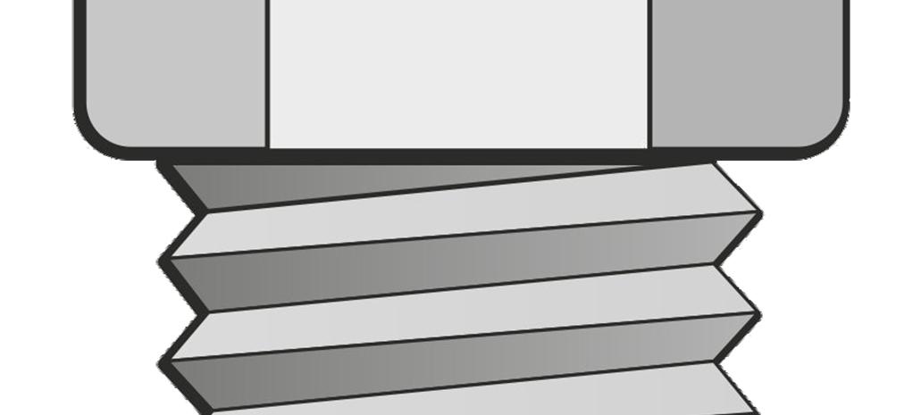
4 Basic installation procedure 1. Insert the bolt into the connection finger tight with the washer under the nut and in contact with the washer face of the nut (Fig 1). If two washers are being used, ensure the washer under the head is placed bevelled edge facing the bolt head. Fig Using the non-impacting electric shear wrench, engage the inner socket over the bolt spline and the outer socket over the nut (Fig 2). Ensure that both inner and outer sockets are fully engaged before proceeding. Fig 2.

5 3. Press the trigger switch. The outer socket rotates clockwise and tightens the nut. When the correct preload is reached the outer socket stops rotating, the inner socket counter rotates and shears the spline off (Fig 3) Fig Stop the wrench and pull the outer socket off the nut. The spline is retained in the inner socket. The wrench has a second trigger to eject the spline safely (Fig 4). Ensure that the wrench motor has come to rest prior to engaging the next bolt. Fig 4.
.")
6 Greenkote PM1 Greenkote is a metal surface treatment for the prevention of corrosion and the name simply relates to the process. Greenkote PM1 is a Thermo-Chemical Surface Modification (TCSM) process which gives better protection that electro-galvanizing and mechanical galvanising and offers similar protection to hot dip galvanising. Sets coated with Greenkote are ready for installation and no additional treatments are necessary. T Washing T washing or etching of bolts prior to installation SHOULD NOT BE DONE. Greenkote provides a very good surface for paint adhesion (sample paint pulloff tests available upon request) Tightening of TCBs Before commencement of preloading, the connected components shall be fitted together and the bolts in the assembly shall be brought to a snug tight condition. This tightening process shall be carried out from bolt to bolt of the group starting from the most rigid part of the connection and moving progressively towards the least rigid part (contact to non-contact surfaces). In order to ensure that the preload in fully installed bolts meets the specified minimum preload requirement, the installation process consists of two tightening stages. The first stage applies a bedding torque to the bolts to ensure a firm contact between components. Pre-tensioning (stage 1) can be accomplished by: i. using the shear wrench but only snugging bolts and UnotU shearing off the splines. When using this method the operator will notice a distinct change in the sound/tone of the wrench motor. This indicates that pre-tensioning has commenced and a bedding torque is being applied. If pre-tensioning has occurred, then when the power trigger is disengaged the wrench gearing will backtrack and reverse allowing the tool to be easily removed from that particular bolt. This whole process can be felt by the operator. or ii. using a standard nut runner/impact wrench with a deep socket to pull all surfaces into contact without involving the bolt spline; NOTE If mating surfaces are significantly distorted or misaligned then slave bolts should be used. TCBs can be used as slave bolts but they must be clearly marked and then replaced prior to final completion of the joint.
 Tightening of TCBs Before commencement of preloading, the connected components shall be")
7 The second tightening stage can only be achieved using a shear wrench. When the spline end of the bolt shears off at the break neck, full preload has been induced. If the assembly cannot be installed using shear wrenches, tightening shall be carried out in a conventional manner by: i. using the torque method with the aid of the k-class K2 information or ii. using a direct tension indicator. (K2 values can be provided upon request) Inspection Five bolt assemblies per diameter lot are systematically tested in accordance with European standards. Axial loads are recorded onto the Certificates of Inspection for TCB assemblies being delivered to site / works. After the spline of the bolt has sheared, the bolt tension should be equal to or greater than those values as required by the specification (see table 1). Since the quality assurance and integrity of the bolted connection is determined by the bolt itself, visual inspection of the bolt spline removal is sufficient. EN Tightening of preloaded bolts General Unless otherwise specified, nominal minimal preloading force F p, c shall be taken as: F p, c = 0.7 f ub. A s where f ub is the ultimate strength of the bolt material and A s is the stress area of the bolt as defined in EN and specified in Table 1. This level of preload shall be used for all slip resistant preloaded connections and for all the other preloaded assemblies unless a lower level of preloaded is specified. Table 1 Values of F p, c in kn Bolt diameter M12 M16 M20 M22 M24 M27 M30 M HRC

8 Fail Safe bolts It is important to understand the difference between tension control bolts and conventional preloaded bolts. As with any threaded fastener an occasional failure can occur. This is generally attributed to a problem during installation and can be the result of several factors including the following: Using a TCB as a slave bolt Alignment problems Foreign materials in the threads such as grit, mastic, oil etc Temperature Moisture In all of these cases, the friction co-efficient of the TCB set reduces resulting in the dumb tool continuing to take the least line of resistance (rotate the outer socket). One of two things will happen. Either: i. the threads will strip in which case the spline will not be removed or ii. the threads will hold and the increased preload will break the bolt due to torsional overload. IN EITHER CASE THE OPERATOR WILL BE AWARE AND THE ASSEMBLY WILL ALWAYS FAIL-TO-SAFE These bolts should be removed and replaced with new ones. If, on inspection it can be seen that the spline has sheared off, then one can be certain that the bolt is installed correctly. It is not possible to properly remove the spline during installation AND the bolt break afterwards without additional forces being applied, thus reinforcing the fail-to-safe properties of this type of bolt system. Example of thread stripping Example of torsional overload
. One of two things will happen. Either: i. the threads will strip in which case the spline will not be removed or ii.")
9 Changing of sockets Loosen the 2 set screws on the side of the socket (keep screws safe) Remove the socket set Push central portion of inner socket with screwdriver or correct size bolt spline as below sockets will disassemble To reassemble, connect both inner and outer sockets push central portion of inner socket with a correctly sized bolt (with spline) to assemble both parts fully Place assembled socket over ejector rod and socket holder on the shear wrench When a gap remains between the outer socket and socket holder, simply insert a correctly sized bolt spline into the inner socket thus allowing the inner socket to drop and become correctly seated into the socket holder Retighten grub screws

10 Shear Wrench Maintenance Maintain the wrench in a state of cleanliness as with any other electrical tool Check electric cable and plug regularly replace if damaged to avoid electric shock Do not pick up or carry the shear wrench by the electric cable Clean sockets occasionally with a dry cloth to avoid build up of debris/dirt Change motors carbon brushes when necessary. The length of the brush needs to be more than 6mm. If shorter than this an insulation pin protrudes through the carbon, disabling further motor operations to protect the armature To maintain the shear wrench in good condition and service, return to TCB Ltd every 6 months or 30,000 bolt installations whichever is first. Publication No /A Copyright TCB Ltd 2014


11

Rebuild Instructions for 70001 and 70010 Transmission
 Rebuild Instructions for 70001 and 70010 Transmission Brinn, Incorporated 1615 Tech Drive Bay City, MI 48706 Telephone 989.686.8920 Fax 989.686.6520 www.brinninc.com Notice Read all instructions before
1.8 CRANKSHAFT OIL SEALS
 SERIES 60 SERVICE MANUAL 1.8 CRANKSHAFT OIL SEALS An oil seal is fitted between each end of the crankshaft and the bores of the flywheel housing and gear case cover to retain the lubricating oil in the
Structural Bolting. Notice the Grade 5 has a much smaller head configuration and a shorter shank then the A325 structural bolt. Rev.
 Structural Bolting ASTM A325 and ASTM A490 are the two U.S. standard structural bolts. When looking at the mechanical requirements of bolts it appears that an ASTM A325 and SAE J429 Grade 5 are identical
Tri-Homo Style Operation and Maintenance Instructions
 Tri-Homo Style Operation and Maintenance Instructions One Research Drive Stratford, CT 06615 (203) 375-0063 www.sonicmixing.com 1 Installation and Start-up Do not perform following adjustments without
Drive shaft, servicing
 Volkswagen Passat B6 - Drive shaft, servicing Стр. 1 из 41 40-7 Drive shaft, servicing Drive shafts, overview I - Assembly overview: Drive axle with CV joint VL100 40-7, Drive axle with CV joint VL100,
STEERING SYSTEM - POWER
 STEERING SYSTEM - POWER 1990 Nissan 240SX 1990 STEERING Nissan - Power Rack & Pinion Axxess, Maxima, Pulsar NX, Sentra, Stanza, 240SX, 300ZX DESCRIPTION The power steering system consists of a rack and
Char-Lynn Hydraulic Motor. Repair Information. 10 000 Series. October, 1997
 Char-Lynn Hydraulic Motor October, 1997 Repair Information Geroler Motor Two Speed 001 27 Retainer inside bore of valve plate bearingless motors only 4 15 16 3 6 35 Parts Drawing 25 2 2 1 19 17 36 40 47
Reaction Torque Sensor
 Force 1 1 N m up to 1 000 1 000 N m Type 9329A 9389A These easy to install piezoelectric reaction torque sensors are particularly suitable for measuring rapidly changing torques at non-rotating shafts.
NORSOK Compact Flange Installation and Assembly Procedure
 NORSOK Compact Flange Installation and Assembly Procedure Hytorc Norway www.hytorc.no P.Nødland. Page 2 INTRODUCTION Scope The following main operations are covered in this section: Assembly/disassembly
ROTARY TUMBLER INSTRUCTIONS AND PARTS LIST
 ROTARY TUMBLER INSTRUCTIONS AND PARTS LIST Model 3-1.5B Model 45C Model 33B LORTONE 12130 Cyrus Way Mukilteo, WA 98275 (425) 493-1600 SETTING UP YOUR MACHINE For 45C Unit Only (33B & 3-1.5B already assembled)
758 Heavy-duty Ratchet Guy Wire Cutter
 INSTRUCTION MANUAL 758 Heavy-duty Ratchet Guy Wire Cutter Read and understand all of the instructions and safety information in this manual before operating or servicing this tool. Register this product
Installation instruction CASAFLEX - Connecting piece DN 100
 1 CASAFLEX - 11 10 114,3 x 4,5 3 5 2 4 1 7 6 8 12 9 Do not begin work until you have read the installation instruction carefully. 1 internal backing sleeve 2 graphite packing 3 connecting piece 4 thrust
M128 SERVICE MANUAL- M128 MODEL #S-11 MANUAL CAN OPENER
 SERVICE MANUAL- M128 MODEL #S-11 MANUAL CAN OPENER 1 Model S-11 Can Opener Assembly Procedure The Model S-11 can opener will be assembled according to the following procedure: I. Model S-11 Handle and
Installation guide for the SafeLine type anchorage device. Tested in compliance with EN 795: 1996. No.: SE-...
 Installation guide for the SafeLine type anchorage device Tested in compliance with EN 795: 1996 No.: SE-... Version: 09.10.2008 SE 67 Subject to technical alterations! Contents 1. General information
ROTARY TUMBLER INSTRUCTIONS AND PARTS LIST
 ROTARY TUMBLER INSTRUCTIONS AND PARTS LIST Model QT66 Model QT12 Model QT6 LORTONE 12130 Cyrus Way Mukilteo, WA 98275 (425) 493-1600 SETTING UP YOUR MACHINE Install The Barrel Guide: Using the machine
Front axle components, overview
 just a test. Front axle components, overview 40-1 General Information Load bearing components and parts of the suspension must not be welded or straightened. Vehicles without drive axle must not be moved,
18974 (736) Singer No. 20-2. SINGER No. 20-2 ELECTRIC SEWING MACHINE INSTRUCTION MANUAL
 Singer No. 20-2. SINGER No. 20-2 ELECTRIC SEWING MACHINE INSTRUCTION MANUAL") SINGER No. 20-2 ELECTRIC SEWING MACHINE INSTRUCTION MANUAL Next Page Main Parts Accessories To start the Motor To Stop the Motor To Change the Speed Needles and Thread Relative Sizes of Needle and Thread
SINGER No. 20-2 ELECTRIC SEWING MACHINE INSTRUCTION MANUAL Next Page Main Parts Accessories To start the Motor To Stop the Motor To Change the Speed Needles and Thread Relative Sizes of Needle and Thread
Original Assembly Guide
 TCT Multipurpose Single Bevel Sliding Compound Mitre Saw Original Assembly Guide Read instructions before assembling this tool. Table of Contents GB Assembly Guide Read instructions before assembling this
Round Housing with Side Ports
 Power Steering Steering Control Unit (SCU) Parts and Repair Information 5 Series Steering Control Units 001 Square Housing with Side Ports Round Housing with Side Ports T E L RP Round Housing with End
Conceptual Design of Buildings (Course unit code 1C2)
") (Course unit code 1C2) Module C Design of Steel Members J.P. Jaspart (University of Liège) 520121-1-2011-1-CZ-ERA MUNDUS-EMMC Bolts are the main type of fasteners used in steel joints. The main geometrical
(Course unit code 1C2) Module C Design of Steel Members J.P. Jaspart (University of Liège) 520121-1-2011-1-CZ-ERA MUNDUS-EMMC Bolts are the main type of fasteners used in steel joints. The main geometrical
ARVINMERITOR UNITIZED FRONT WHEEL HUB INSPECTION AND MAINTENANCE
 SERVICE BULLETIN (Also applies to Mack Trucks Australia) NUMBER: SB-423-002 DATE: 8/23/02 MODEL: All with FF981 Front Axle ARVINMERITOR UNITIZED FRONT WHEEL HUB INSPECTION AND MAINTENANCE The ArvinMeritor
300 SERIES 331, 332, 333, 344, 356 AND 367 MODELS
 Section: MOYNO 500 PUMPS Page: 1 of 8 Date: March 1, 1998 SERVICE MANUAL MOYNO 500 PUMPS 300 SERIES 331, 332, 333, 344, 356 AND 367 MODELS Mechanical Seal Models Packing Gland Models MODELS DESIGN FEATURES
Char-Lynn Spool Valve Hydraulic Motors. Repair Information. W Series Geroler Motors
 Char-Lynn Spool Valve Hydraulic Motors Repair Information W Series Geroler Motors with Parking Brake 004 Nut Key Ring, Retaining Bearing Ring, Retaining Ring, Retaining Washer (Thick), Pressure Washer,
Machine needle shut-off nozzle type HP
 Machine needle shut-off nozzle type HP pneumatically or hydraulically controlled Index of contents Chapter Page Safety instructions... 2 Installation instructions... 3 - Installation steps... 3 Initial
White Industries Rear Hub Instructions
 White Industries Rear Hub Instructions Tool required: 2mm allen/hex wrench, 19mm socket, 20mm socket, and mallet. 1. Loosen the set screws located in the adjusting collar by using a 2mm allen wrench inserted
KIT PRESSURE PLATE FLYWHEEL DISC ALIGNMENT TOOL 600530 (F01/F03/F05) 600565 (F02/F04)* 600530 (F01/F03/F05) 600565 (F02/F04)*
 600565 (F02/F04)* 600530 (F01/F03/F05) 600565 (F02/F04)*") FORD TWIN-DISC KITS Thank you for purchasing this ACT product. ACT has a long racing heritage supporting countless racers and series champions in many forms of racing. Now you can let ACT s experience
FORD TWIN-DISC KITS Thank you for purchasing this ACT product. ACT has a long racing heritage supporting countless racers and series champions in many forms of racing. Now you can let ACT s experience
P22 Cal..22L.R. Operating Instructions. Semi-Automatic pistol USA. anl_us~1.qxd 13.08.2002 07:52 Seite 1. extractor
 anl_us~1.qxd 13.08.2002 07:52 Seite 1 manual safety extractor stabilizer frontsight slide Loaded chamber indicator rear sight hammer barrel trigger lock muzzle trigger mounting rail manual safety slide
Volkswagen Jetta, Golf, GTI 1999, 2000 Brake System 47 Brakes - Hydraulic Components (Page GR-47)
") 47 Brakes - Hydraulic Components (Page GR-47) FS III front brake calipers, servicing Front brake caliper piston, removing and installing FN 3 front brake calipers, servicing Front caliper piston, removing
47 Brakes - Hydraulic Components (Page GR-47) FS III front brake calipers, servicing Front brake caliper piston, removing and installing FN 3 front brake calipers, servicing Front caliper piston, removing
S&G Model 2937 Group 1 Combination Lock
 Installation and Combination Changing Instructions S&G Model 2937 Group 1 Combination Lock NOTE: READ COMPLETE INSTRUCTIONS BEFORE INSTALLATION These instructions should be followed when installing the
3. Loosen 3 x grub screws in the Dec end cap and unscrew the cap and counterweight shaft. NEQ6 Belt Modification Kit.
 NEQ6 Belt Modification Kit. Thank you for your purchase. Please read these instructions fully before fitting. Your package should contain 2 off 47 & 2 off 12 tooth aluminium pulleys 2 off belts 6mm wide
SERVICE PARTS LIST PAGE 1 OF 6 BASE ASSEMBLY SPECIFY CATALOG NO. AND SERIAL NO. WHEN ORDERING PARTS 12" DUAL BEVEL COMPOUND MITER SAW B27A
 PAGE 1 OF 6 BASE ASSEMBLY 00 0 EXAMPLE: Component Parts (Small #) Are Included When Ordering The Assembly (Large #). SPECIFY CATALOG NO. AND NO. WHEN ORDERING PARTS 1 02-80-0050 Thrust Bearing (1) 2 05-80-0510
Owner s Manual Read and keep this manual. Patents World Wide
 Owner s Manual Read and keep this manual. Patents World Wide S & S Industries, Inc., Sarasota, FL, USA www.trail-gator.com Copyright 2008 All Rights Reserved The following manual is provided to assist
5800 Temperature Sensor Cable Assembly
 5800 Temperature Sensor Cable Assembly Removal and Replacement Instruction Sheet #60-4702-070 Revision D, January 14, 2013 Overview The 5800 has two refrigeration temperature sensors, one attached to the
Assembly and Usage Instructions
 Assembly and Usage Instructions A Product 5885 West Van Horn Tavern Road Columbia, MO 65203 www.caldwellshooting.com Instruction #1001667 Limited Warranty Every Caldwell product is warrantied to be free
PRODUCT MANUAL - M090
 PRODUCT MANUAL - M090 MODEL 203/266 ELECTRIC CAN OPENER 1 SAFETY CAUTION: SEVERED CAN LIDS HAVE CUTTING EDGES. USE OF A PROTECTIVE GLOVE OR TONGS IS ADVISED WHEN HANDLING LIDS. WARNING To avoid risk of
2003 Audi A4. AUDI' '3.0L V6 - AVK Engine - A4 & A6
 Installation (A4) CAUTION: Before installation, ensure camshafts are aligned, crankshaft is locked in place and camshaft gear bolts are loose as described in removal procedures. When turning camshaft,
Electrically Released Brake ER-825, ER-1225 with Pin Drive Armatues for Montgomery Kone
 P-230 819-0466 Electrically Released Brake ER-825, ER-1225 with Pin Drive Armatues for Montgomery Kone Installation & Operating Instructions Contents Introduction........................... 3 Installation
INSTALLATION INSTRUCTIONS
 Installation Instructions Ford Twin Disc Kits Serial #: Thank you for purchasing this quality ACT product. ACT has a long racing heritage supporting countless racers and series champions in many forms
TRS 090/105 Compressor. Repair Procedures
 TRS 090/105 Compressor Repair Procedures GENERAL FGG All repair and service operations should be performed on a clean bench and with the use of clean tools. Use genuine parts and correct tools for all
Depending on which elastic support you have you can secure the V2 power unit to the following seat bracket tubes: EXTERNAL DIAMETER 27.
 ASSEMBLY 1 - EPS V2 POWER UNIT (SOLUTION 5) 1.1 - POSITIONING INSIDE THE SEAT TUBE WITH ELASTIC SUPPORT IN THE SEAT BRACKET TUBE Depending on which elastic support you have you can secure the V2 power
AXLE SHAFTS - FRONT. 1998 Pontiac Bonneville MODEL IDENTIFICATION DESCRIPTION & OPERATION TROUBLE SHOOTING REMOVAL & INSTALLATION
 AXLE SHAFTS - FRONT 1998 Pontiac Bonneville 1998-99 DRIVE AXLES FWD Axle Shafts - Cars - "C", "G" & "H" Bodies GM Aurora, Bonneville, Eighty Eight, LeSabre, LSS, Park Avenue, Regency, Riviera MODEL IDENTIFICATION
Product Notice. Safety Notice: Sales Hold
 Product Notice Ariens Company 655 W. Ryan St. Brillion, WI 54110 www.ariens.com Product Family: Ariens and Gravely 36 Power Brushes Subject: Sales Hold Inspect and Repair Dealer Action: SALES HOLD Do not
2100 AD 015 0009 Mirror Elevator Ball Nut Replacement Procedure
 2100 AD 015 0009 Mirror Elevator Ball Nut Replacement Procedure Derek Guenther 1/28/2015 Rev. Purpose The purpose of this document is to describe the procedure necessary to replace one of the ball nuts
ABV20 Air Actuated Boiler Blowdown Valve Installation and Maintenance Instructions
 4057250/8 IM-P405-16 AB Issue 8 ABV20 Air Actuated Boiler Blowdown Valve Installation and Maintenance Instructions 1 General safety information 2 General product information 3 Installation 4 Operation
Volkswagen Jetta, Golf, GTI 1999, 2000 Brake System 46 Brakes - Mechanical Components (Page GR-46)
") 46 Brakes - Mechanical Components (Page GR-46) Front brakes Brake pads, removing and installing Brake pads, removing and installing FN 3 brake caliper, servicing FS III brake caliper, servicing Rear wheel
46 Brakes - Mechanical Components (Page GR-46) Front brakes Brake pads, removing and installing Brake pads, removing and installing FN 3 brake caliper, servicing FS III brake caliper, servicing Rear wheel
Two most common lock nut groups: 1-Prevailing Torque Type Lock Nuts:
 Two most common lock nut groups: 1. PREVAILING TORQUE a design feature of the lock nut produces friction between threads of mated components thereby increasing the force needed to tighten as well as loosen
CAST IRON THE BASICS. Heatline - Cast Iron Radiators SMOOTH FLAT FILE TO REMOVE ANY SWARF. ONE TIME. ASSEMBLY. JOINTS SHOULD BE TIGHTENED.
 CAST IRON THE BASICS 1. DO NOT LIFT ON YOUR OWN. 2. ONLY LIFT THE RADIATOR VERTICALLY. 3. DO NOT LIFT MORE THAN 8/10 SECTIONS AT ANY ONE TIME. 4. POSITION THE RADIATOR BEFORE FINAL ASSEMBLY. 5. THIS PRODUCT
STORAGE, INSTALLATION AND MAINTENANCE PROCEDURES
 GATE VALVE O.S. & Y 1.0 Periodic Inspections 1.1 The valve stem packing should be inspected at least monthly. If the stem packing shows signs of leakage, simply tighten the adjusting nuts to compress the
Wafer Check Valve ASAHI AV VALVES. Contents. User s Manual. (1) Be sure to read the following description of our product warranty 1
 Be sure to read the following description of our product warranty 1") Serial No. H-V066-E-2 Wafer Check Valve User s Manual Contents (1) Be sure to read the following description of our product warranty 1 (2) General operating instructions 2 (3) General instructions for
Serial No. H-V066-E-2 Wafer Check Valve User s Manual Contents (1) Be sure to read the following description of our product warranty 1 (2) General operating instructions 2 (3) General instructions for
Parts#MB003-003 Reverse Gear MAMBA (Monoblock for Cable operated) For 5 speed Trans., '87 to '06 Big Twin models (except '06 Dyna)
 For 5 speed Trans., '87 to '06 Big Twin models (except '06 Dyna)") Installation Instructions Reverse Gear MAMBA (Monoblock for Cable operated) Read and become familiar with these installation instructions before start. Two Piece for H-D 5 Speed Trans., Cable operated
Installation Instructions Reverse Gear MAMBA (Monoblock for Cable operated) Read and become familiar with these installation instructions before start. Two Piece for H-D 5 Speed Trans., Cable operated
Rear wheel brakes, servicing. Стр. 1 из 45. Note:
 Volkswagen Touareg - Rear wheel brakes, servicing Стр. 1 из 45 46-2 Rear wheel brakes, servicing Rear brakes, FN 44 brake caliper, servicing Note: After replacing brake pads, depress brake pedal firmly
STEERING HANDLEBAR/FRONT WHEEL/ FRONT SHOCK ABSORBER
 14 14 STEERING HANDLEBAR/FRONT WHEEL/ SCHEMATIC DRAWING ------------------------------------------------- 14-1 SERVICE INFORMATION------------------------------------------------ 14-2 TROUBLESHOOTING-----------------------------------------------------
Bolting Galvanized Steel
 Bolting Galvanized Steel This chapter gives information on the characteristics, advantages and economics of bolted galvanized structures and zinc coated fasteners, and offers comment on bolting procedures
Installation Instructions Avalanche XUV Cap IMPORTANT! IMPORTANT!
 Installation Instructions Avalanche XUV Cap IMPORTANT! Read all instructions carefully before commencing any work. Always wear safety equipment. Some installation steps will require two or more installers.
LU6X-130 Instructions and Parts List (including LU6X Basic) Operating Instructions
 Operating Instructions") LORTONE LU6X-130 Item # 061-092 LU6X Basic Item # 061-090 LU6X-130 Instructions and Parts List (including LU6X Basic) Operating Instructions Introduction The LU6X is one the most versatile pieces of equipment
LORTONE LU6X-130 Item # 061-092 LU6X Basic Item # 061-090 LU6X-130 Instructions and Parts List (including LU6X Basic) Operating Instructions Introduction The LU6X is one the most versatile pieces of equipment
AstroSystems Digital Setting Circles for Zhumell, GSO, Apertura and Astro-Tech
 AstroSystems Digital Setting Circles for Zhumell, GSO, Apertura and Astro-Tech Components 1 Sky Commander Digital Setting Circle Computer 2 Encoders 10,000 step 1 Sky Commander Digital Setting Circle Manual
TECHNICAL INFORMATION
 TECHNICAL INFORMATION Models No. 2012NB Description 304mm (12") Automatic Thickness Planer CONCEPTION AND MAIN APPLICATIONS * Compact and light weight (27 Kg./59 lbs) automatic thickness planer for easier
POSEIDON 2-29, 2-25 & 2-22 POSEIDON 2-29, 2-25 & 2-22 XT
 POSEION 2-29, 2-25 & 2-22 POSEION 2-29, 2-25 & 2-22 XT Repair Manual Index A. Safety precautions 3 B. Technical data 4 C. Structure 5-6. Service / Repair 7-23 E. Tools 24 F. Function 25-26 G. Electric
2008 ACCORD - Front Knuckle/Hub/Wheel Bearing Replacement (page 18-13)
") 2008 ACCORD - Front Knuckle/Hub/Wheel Bearing Replacement (page 18-13) Exploded View Special Tools Required Ball joint remover, 28 mm 07MAC-SL0A202 Hub dis/assembly tool 07GAF-SD40100 Bearing driver attachment,
2008 ACCORD - Front Knuckle/Hub/Wheel Bearing Replacement (page 18-13) Exploded View Special Tools Required Ball joint remover, 28 mm 07MAC-SL0A202 Hub dis/assembly tool 07GAF-SD40100 Bearing driver attachment,
BETTIS CONVERSION INSTRUCTIONS TO CONVERT HD SERIES ACTUATORS TO HD-M3, HD-SR-M3 HD-M3HW OR HD-SR-M3HW SERIES PNEUMATIC ACTUATORS
 BETTIS CONVERSION INSTRUCTIONS TO CONVERT HD SERIES ACTUATORS TO HD-M3, HD-SR-M3 HD-M3HW OR HD-SR-M3HW SERIES PNEUMATIC ACTUATORS PART NUMBER: 132581 REVISION: A RELEASE DATE: 24 March 2000 Page 1 of 10
SERIES ASM NEOPRENE/EPMD FLANGED SINGLE SPHERE CONNECTOR CONNECTORS. Pressures to 225 PSIG (15.51 barg) Temperatures to 230ºF (110ºC)
 Temperatures to 230ºF (110ºC)") APPLICATIONS Process Industry Weak Acids Alkalies Compressed Air Pulp & Paper MODELS ASM - Flanged Connection OPTIONS Control Rods Oil & Gas Water & Waste Pump suction & discharge Sea water Chemical lines
APPLICATIONS Process Industry Weak Acids Alkalies Compressed Air Pulp & Paper MODELS ASM - Flanged Connection OPTIONS Control Rods Oil & Gas Water & Waste Pump suction & discharge Sea water Chemical lines
Cable Drum Installation
 20 Cable Drum Installation COUNTERBALANCE None Shake the TorqueMaster spring tube gently to extend the winding shafts out about 5" on each side. For single spring applications, there will be no left hand
MBSAW. Meat Cutting Band Saw With Meat Grinder Assembly & Operating Instructions
 06/2011 MBSAW Meat Cutting Band Saw With Meat Grinder Assembly & Operating Instructions READ ALL INSTRUCTIONS AND WARNINGS BEFORE USING THIS PRODUCT. This manual provides important information on proper
pottery barn kids MADELINE BUNK BED
 pottery barn kids MADELINE BUNK BED! WARNING: Failure to follow these warnings and assembly instructions could result in serious injury or death. To help prevent serious or fatal injuries from entrapment
Mounting Instructions. Torque Transducer. A0329 3.2 en
 Mounting Instructions Torque Transducer T5 T5 Contents 3 Page Safety instructions.............................................. 4 1 Measuring characteristics..................................... 7 2 Mounting.....................................................
SERIES NG 1800 STRUCTURAL STEELWORK
 MANUAL OF CONTRACT DOCUMENTS FOR HIGHWAY WORKS VOLUME 2 NOTES FOR GUIDANCE ON THE SPECIFICATION FOR HIGHWAY WORKS SERIES NG 1800 STRUCTURAL STEELWORK Contents Clause Title Page NG 1800 (08/14) General
Explosion proof enclosures
 1 of 7 Explosion proof enclosures DE8 C 2 of 7 The Ex d enclosures are rugged and designed for harsh environment like: Oil and gas industry Chemical industry Pharmaceutical industry Agribusiness Without
2006 HEADSHOK Service Video #1
 LEFTY SPEED DLR DAMPING CARTRIDGE This document explains how to properly remove, disassemble, inspect, reassemble and reinstall the Lefty Speed DLR2 damping cartridge. It is a document to be used in conjunction
ASSEMBLY DIAGRAM AND ASSEMBLY REFERENCE ULTIMA OLD SCHOOL 2 EVO & TC BELT DRIVE UNITS
 ASSEMBLY DIAGRAM AND ASSEMBLY REFERENCE ULTIMA OLD SCHOOL 2 EVO & TC BELT DRIVE UNITS BELT DRIVE ASSEMBLIES Part# 58-850 2 Old School Belt Drive Assembly - Polished Part# 58-851 2 Old School Belt Drive
IMPORTANT DOCUMENTATION DO NOT DISCARD!
 PART NO.: 6441-263C SERIES GRT 3 JAW PARALLEL GRIPPERS INFORMATION SHEET IMPORTANT DOCUMENTATION DO NOT DISCARD! Use this information sheet to assist with gripper installation and setup. File with maintenance
Europeiskt Tekniskt Godkännande European Technical Approval
 SITAC Box 553 SE 371 23 Karlskrona SWEDEN MEMBER OF EOTA Tfn.: +46-(0)10-516 63 00 Fax: +46-(0)455-206 88 E-mail: [email protected] Europeiskt Tekniskt Godkännande European Technical Approval ETA-12/0257 Handelsnamn
3097 en - 2013.06 / e. This manual is to be given to the end user POULIBLOC 2000-3000. Shaft mount reducer. Installation
 097 en - 0.06 / e 8 en This manual is to be given to the end user POULIBLOC 000-000 Installation LEOY-SOME ISTALLATIO POULIBLOC 000-000 097 en - 0.06 / e This document complements the general instructions
ZAPPY 3 OWNER S MANUAL. Read this manual completely before riding your Electric ZAPPY 3.
 ZAPPY 3 OWNER S MANUAL Read this manual completely before riding your Electric ZAPPY 3. TECHNICAL INFORMATION Model No. : ZAPPY 3 Product size Type of motor Motor power Battery type Battery Charger Charging
DiscPlus DX195 and DX225 Air Disc Brakes
 Revised 11-04 Technical Bulletin Revised 1 Technical 11-04 Bulletin DiscPlus DX195 and DX225 Air Disc Brakes Inspection, Installation and Diagnostics Air Disc Brake Inspection Intervals and Procedures
TYPE E Main Valve Sizes 3 /8 through 12
 SD 3001F PRINTED IN U.S.A. SD 3001F/0707 A B TYPE E MAIN VALVE C D E TYPE E Main Valve Sizes 3 /8 through 12 The Spence Type E Main Valve is of normally closed, single seat design featuring packless construction,
Written By: Walter Galan
 Installing iphone 4S Display Assembly Written By: Walter Galan TOOLS: Phillips 00 Screwdriver (1) Plastic Opening Tools (1) PARTS: iphone 4S Display Assembly (1) iphone 4 and 4S Screen Protector (1) Small
Triple Threat 3-in-1 Game Table 3 IN 1 GAME TABLE
 NG0M Triple Threat 3-in- Game Table 3 IN GAME TABLE Thank 3 in Y Game Table Thank you for your purchase of our product. We work around the clock and around the globe to ensure that our products maintain
Precision Miniature Load Cell. Models 8431, 8432 with Overload Protection
 w Technical Product Information Precision Miniature Load Cell with Overload Protection 1. Introduction The load cells in the model 8431 and 8432 series are primarily designed for the measurement of force
OPERATING INSTRUCTIONS FOR
 OPERATING INSTRUCTIONS FOR MEDECO KEY MACHINES FOR MEDECO ORIGINAL, BIAXIAL, MEDECO 3, KEYMARK CLASSIC & KEYMARK X4 PRODUCTS MEDECO HIGH SECURITY LOCKS ASSUMES NO RESPONSIBILITY FOR INJURY OR PROPERTY
Pipe Flange Bolting Guide Aztec Bolting Services, Inc.
 Pipe Flange Bolting Guide Aztec Bolting Services, Inc. 1. Introduction: In the quest to eliminate leaks in piping and pressure vessel systems, it is necessary to first develop an understanding of the mechanisms
Repair of Hyd-ro-ac Actuators
 Repair of Hyd-ro-ac Actuators OVERHAUL INSTRUCTIONS SS-.2A-1V SS-.5A-1V SS-.5A-2V Read the entire contents of these instructions before installing the actuator and before making any connections to the
These features have made Lo Torc valves the choice of high pressure plug value users, worldwide:
 LO TORC Plug Valve The high value, dependable performance, and low maintenance requirements of Halliburton Lo Torc valves can help reduce overall operating costs and help cut downtime. These features have
3. SEISCO PARTS & SERVICE REMOVAL AND REPAIR GUIDE
 4 3. SEISCO PARTS & SERVICE REMOVAL AND REPAIR GUIDE A. Changing the Control Board B. Replacing a Heating Element C. Thermistor Replacement D. High Limit Switch Replacement E. Level Detector Replacement
Step-by-step instructions:
 Spark plug thread repair for Ford Triton cylinder heads Step-by-step instructions: Identification Installation Verification Specifically designed and tested for 4.6L, 5.4L, and 6.8L 2 and 4 valve heads,
ARTICLE BEGINNING APPLICATION IDENTIFICATION DESCRIPTION LUBRICATION & ADJUSTMENT TROUBLE SHOOTING. MANUAL TRANSMISSIONS Saab 5-Speed Transaxle
 Article Text ARTICLE BEGINNING MANUAL TRANSMISSIONS Saab 5-Speed Transaxle APPLICATION TRANSMISSION APPLICATION ÄÄÄÄÄÄÄÄÄÄÄÄÄÄÄÄÄÄÄÄÄÄÄÄÄÄÄÄÄÄÄÄÄÄÄÄÄÄÄÄÄÄÄÄÄÄÄÄÄÄÄÄÄÄÄÄÄÄÄÄ Vehicle Application Transmission
Mechanical Joint Restraints
 -15 PVC Pipe Restrainer The PVC mechanical joint restrainer eliminates the need for thrust blocking, tie rodding, or harnessing mechanical joint fittings when they are used with PVC pipe. The key to the
GATE VALVES ASAHI AV VALVES. Type P (Standard: Plug) Type S (Soft Seal) Contents. (1) Be sure to read the following warranty clauses of our product 1
 Type S (Soft Seal) Contents. (1) Be sure to read the following warranty clauses of our product 1") Serial No. H-V011-E-11 GATE VALVES Type P (Standard: Plug) Type S (Soft Seal) Contents (1) Be sure to read the following warranty clauses of our product 1 User s Manual (2) General operating instructions
Serial No. H-V011-E-11 GATE VALVES Type P (Standard: Plug) Type S (Soft Seal) Contents (1) Be sure to read the following warranty clauses of our product 1 User s Manual (2) General operating instructions
Welding Reel ERA 4000 Service Manual
 AERO-MOTIVE COMPANY A Woodhead Industries, Inc. Subsidiary Welding Reel ERA 4000 Service Manual IMPORTANT SAFETY INSTRUCTIONS Please read this manual carefully and follow its instructions. Improper use
Front brakes (FN- 3), servicing
, servicing") j a t Front brakes (FN- 3), servicing 46-1 Front brakes, servicing Note: Install complete repair kit. After replacing brake pads and before moving vehicle, depress brake pedal several times firmly to properly
j a t Front brakes (FN- 3), servicing 46-1 Front brakes, servicing Note: Install complete repair kit. After replacing brake pads and before moving vehicle, depress brake pedal several times firmly to properly
Mechanical Installation
 Page -1-1. INTRODUCTION AND PURPOSE 1.1. This specification covers the installation, testing and precommissioning of mechanical equipment. Work is to be performed in conjunction with the manufacturer s
The Ford Model A Water Pump
 The Ford Model A Water Pump George Washington Chapter, Inc. 3903 Old Lee Highway Fairfax, VA 22030 1 Table of Contents Introduction/Specifications.. 3 1. Water Pump Inspection and Removal. 4 a. Removal..
Slide the new steering column shaft through the steering column from the driver compartment.
 Slide the new steering column shaft through the steering column from the driver compartment. Push the column shaft through the steering column until the machined end is out past the column lower bushing.
UPPER TENSION MECHANISM - (66 & 99 models)
") UPPER TENSION MECHANISM - (66 & 99 models)..006 The principals of thread tension have already been covered in the section on How a Sewing Machine Works page [] E - 4. () The majority of tension adjustments
UPPER TENSION MECHANISM - (66 & 99 models)..006 The principals of thread tension have already been covered in the section on How a Sewing Machine Works page [] E - 4. () The majority of tension adjustments
MICROMETER ADJUSTABLE CLICK TYPE TORQUE WRENCH REPAIR, MAINTENANCE AND TROUBLESHOOTING MANUAL
 MICROMETER ADJUSTALE CLICK TYPE TORQUE WRENCH REPAIR, MAINTENANCE AND TROULESHOOTING MANUAL SUGGESTED PRICE $35.00 PART NUMER: 21-201-01 ISSUED NOVEMER, 2001 TALE OF CONTENTS TITLE PAGE(S) SAFETY INSTRUCTIONS
HAND CRIMP TOOL Specification Sheet Order No. 63819-0900
 HAND CRIMP TOOL Specification Sheet Order No. 63819-0900 FEATURES TYPE 4D ΠA full cycle ratcheting hand tool ensures complete crimps ΠErgonomic soft grip handles for comfortable crimping ΠA precision
OPERATORS MANUAL MG22 MEAT GRINDER MG22/0209 ED 1 0011220
 OPERATORS MANUAL MG22 MEAT GRINDER MG22/0209 ED 1 0011220 TO INSURE BOTH SAFE AND TROUBLE-FREE PERFORMANCE, WE STRESS THAT ALL PERSONNEL THAT WILL BE INVOLVED WITH YOUR NEW UNIVEX MEAT GRINDER MUST READ
OWNER S MANUAL Table Tennis Table Patent Pending
 OWNER S MANUAL Table Tennis Table Patent Pending Be sure to write your model number and serial number here for future reference. You can find these numbers printed on the bottom of the table. MODEL # T8179
Reachout Lock Replacement for Andersen 2-Panel and 4-Panel 400 Series Frenchwood Gliding, 200 Series Narroline, and Perma-Shield Gliding Patio Doors
 for Andersen 2-Panel and 4-Panel 400 Series Frenchwood Gliding, 200 Series Narroline, and Perma-Shield Gliding Patio Doors Thank you for choosing Andersen. For questions call 1-888-888-7020. For more information
ORTHOBLOC 3000. Drive systems. Installation. This manual is to be given to the end user. 3996 en - 2013.04 / k. R max - 5 mm.
 en - 01.0 / k 1 en This manual is to be given to the end user --> B7 (0 to 0 ) R max - mm R min + mm ORTHOBLOC 000 Installation LEROY-SOMER Ot 000 en - 01.0 / k NOTE LEROY-SOMER reserves the right to modify