Air-Ride 227 Series. Models: RAD-227, RAD-227C, RAD-227WB, & RAS-227 Owner s Manual
|
|
|
- Agnes James
- 7 years ago
- Views:
Transcription
1 Air-Ride 227 Series Models: RAD-227, RAD-227C, RAD-227WB, & RAS-227 Owner s Manual RAD-227C 100% Air-Ride 34,000-48,000 lb. capacities RAD ,000-25,000 lb. capacities RAD-227WB Wide Base 100% Air-Ride 10,000-25,000 lb. capacities RAS-227 7,000-15,000 lb. capacities P.O. Box 4586 Springfield, MO (fax) 0811

2 Suspension Identification: Ridewell Suspensions are identified by a metal tag attached to the left-hand hanger that indicates model number, capacity, and a date-coded serial number. Consult your vehicle manufactuer for your correct mounting height. Parts: For optimum suspension performance, order only Ridewell parts. Replacement parts for Model RAS-227, RAD-227, RAD-227C, and RAD-227WB are shown on pages of this manual. Sales, Service & Warranty: If you need assistance regarding this product, please contact us and we will be glad to help you. Mailing Address Ridewell Corporation P.O. Box 4586 Springfield, MO Shipping Address Ridewell Corporation 3715 East Farm Rd. 94 Springfield, MO Phones, Fax, , (fax) info@ridewellcorp.com 2

3 Contents Basic Operation Operational Inspection...4 Preventative Maintenance...5 Basic Troubleshooting...6 Axle Alignment Procedures...7 Bushing Replacement Procedures...8 Ride Height/Height Control Valve Adjustment...9 Shock Adjustment Procedure...10 Parts Illustrations Basic Operation When properly maintained and operated within design limits, Ridewell s RAD-227 (Drive Axle), RAS-227 (Steer Axle) and RAD-227WB (Drive Axle Wide Base) will provide many years of trouble-free service. The RAD-227 series suspensions have several unique features which keep maintenance to a minimum and performance at a maximum: % ride on air 2. Parallelogram design promotes road stability allowing axle movement with no change in steering or drive line angle. 3. A patented eccentric bolt and/or screw rod feature allows for simple, positive axle alignment. 4. Rubber bushed pivot points require no lubrication. 5. A self-contained shock absorber that allows precise installation and ensures proper shock and air spring relationship is maintained. 3

4 Basic Operation Continued Air Springs & Height Control Valve Your air-ride suspension is designed to damp the shocks transmitted from road surface to vehicle frame through the air springs. The height control valve is used to maintain the volume of air in the air springs. You may use a single valve system to maintain ride height only or use a double valve system to maintain ride height and level the vehicle. Please check with your vehicle manufacturer for your suspension s ride height. IMPORTANT NOTE: The air springs used on all Model 227 suspensions have internal rubber bumpers designed to carry the vehicle load should air spring failure or sudden loss of air supply occur. Should an air spring fail on a single height control valve system, all of the air springs will deflate allowing the suspension to operate on internal bumpers until repairs can be made. Should an air spring fail on a double height control or leveling valve system, the springs would deflate on one side only. Simply deflate the other side by removing the vertical linkage rod from the valve and rotate the horizontal lever arms down to fully exhaust the springs. Air Pressure & Brake Protection Valve This air-ride suspension is dependent on air pressure from the vehicle supply system. Air pressure must be maintained above 65 p.s.i. before operation. A brake protection valve must be installed in the air system to prevent loss below 65 p.s.i. to ensure safe air brake pressure in the event of air loss in the suspension system. Shock Absorbers The suspension is equipped with shock absorbers to damp dynamic frequencies. The shock absorber is very important and must be maintained to ensure smooth operation. 4 Operational Inspection 1. Inspect all fasteners at hanger to frame connections. 2. Build and maintain vehicle air pressure to 65 p.s.i. minimum. 3. Inspect air springs. Make sure all springs inflate and do not leak. Soap test if leaking is suspected. 4. Check all air connections for leaks and tighten if needed. 5. Inspect air lines. They should be free of sharp edge contact to prevent premature failure. 6. Check for proper ride height. If incorrect, adjust per the Ride Height/Height Control Valve Adjustment section of this manual. 7. Cross members must be installed between hangers.

5 Preventative Maintenance Daily Check for loose or broken parts on or around suspension to prevent any serious problems from occurring. If loose or broken parts are detected, immediate corrective action must be taken. Every 30 Days Check clearances around all moving suspension parts, air springs, tires, and shock absorbers. Any signs of interference should be corrected immediately. Every 90 Days & with Annual Inspection Inspect items required in daily & 30-day inspections. Inspect all welded connections. Inspect all pivot and clamping connections such as the suspension pivots and shock mounts. DO NOT PAINT THIS STICKER RIDEWELL SUSPENSIONS TORQUE CHART BOLT SIZE LUBRICATED THREADS 1½ 1,100 FT. LB. (1,490 N m) 1¼ 1,000 FT. LB. (1,350 N m) 1 1 /8 500 FT. LB. (680 N m) 1 GRADE FT. LB. (490 N m) 1 GRADE FT. LB. (625 N m) 7 /8 350 FT. LB. (475 N m) ¾ GRADE FT. LB. (220 N m) ¾ GRADE FT. LB. (260 N m) 5 /8 100 FT. LB. (135 N m) *¾ 50 FT. LB. (70 N m) *½ 25 FT. LB. (35 N m) *AIR SPRING CONNECTION ONLY After suspension has been in operation for approximately 6,000 miles (10,000 km), all fasteners must be re-tightened to specified torque. Repeat every 50,000 miles (80,000 km). DO NOT OVER TORQUE! Figure 1 #

6 Basic Troubleshooting NOTE: Do not check system until minimum 65 p.s.i. air pressure is built and maintained. 1. All air springs flat or slow to fill - check the following: a. Air pressure b. Air brake protection valve c. Height control valve d. Possible air line leakage 2. Air springs flat on one side of suspension - check the following: a. Air springs b. Height control valve c. Height control valve setting d. Possible air line leakage 3. When vehicle is parked suspension deflates rapidly - check the following: a. Air lines b. Air springs 4. Vehicle pulls to left or right - check the following: a. Tire pressure b. Axle alignment c. Suspension bushings 5. Vehicle has excessive sway - check the following: a. Air springs firmness b. Sway bar bushings c. Torque beam bushings 6

7 Axle Alignment Procedures Procedure 1 For suspensions with eccentric bolts only: 1. Loosen all 1¼ eccentric bolt nuts. 2 Remove anti-turn washers from head of eccentric bolts. 3. Align axle by turning eccentric bolt arrow (on bolt head) on the lower most torque beam to the direction the axle needs to move. 4. Turn the upper eccentric arrow to the same position of the lower arrow. Check alignment and repeat as necessary. 5. After alignment is achieved, install anti-turn washers to eccentric bolt heads. 6. Tighten 1¼ nuts to 1,000 ft. lbs. torque. Procedure 2 For suspensions with threaded rod type adjustable torque arms only: 1. Loosen cast clamp bolts on threaded torque arms. 2 Turn lower most torque arm threaded rod either clockwise or counter-clockwise to lengthen or shorten torque rod as required. 3. Measure new length of lower torque arm using center of mounting bolts as reference. 4. Adjust upper torque arm to match lower arm length. 5. Check alignment and repeat as necessary. 6. Tighten cast clamp bolts on adjustable torque arm to 100 ft. lbs. torque. Procedure 3 For suspensions with eccentric bolt adjustment on lower torque beam and an upper threaded rod type adjustable torque arm: 1. Loosen all 1¼ eccentric bolt nuts. 2 Remove anti-turn washers from eccentric bolt head. 3. Align axle by turning eccentric bolt arrow (on bolt head) to the direction the axle needs to move. 4. Loosen cast clamp bolts on torque arm and adjust the upper threaded rod type torque arm approximately the same distance the axle has moved. Check alignment and repeat as necessary. 5. After alignment is achieved, install anti-turn washer to eccentric bolt head. 6. Tighten 1¼ nuts to 1,000 ft. lbs. torque. 7. Tighten cast clamp bolts on adjustable torque arm to 100 ft. lbs. torque. 7

8 Bushing Replacement Procedures Procedure 1 Replacement of torque beam bushings: 1. Lift frame of vehicle with proper jacks or stands and exhaust air from suspension system. 2. Remove tires from axle. 3. Block axle with proper jacks or stands. 4. Remove anti-turn washers from heads of eccentric bolts. Remove weld from clamp block (if applicable). 5. Remove 1¼ nuts on eccentric bolts. Turn eccentric bolt arrow to 12 o clock position and tap out (otherwise damage to components WILL occur ). CAUTION: DO NOT DAMAGE THREADS). 6. Remove 1½ cap screws from lower beam assembly. 7. Remove torque beams from suspension and press bushings out in hydraulic press. 8. Using an approved rubber lubricant, press in new bushings. Make sure bushings are centered in torque beam sleeve. 9. Install torque beams into suspension. 10. Move axle up or down to proper ride height and torque 1½ cap screws to 1,100 ft. lbs. 11. Re-install eccentric bolts and the 1¼ nuts. 12. Align axle (see Axle Alignment Procedures). 13. Install anti-turn washers after alignment. 14. Torque 1¼ nuts to 1,000 ft. lbs. Procedure 2 Replacement of adjustable torque arms or sway bar bushings: 1. Remove 1 bolts from torque arms or sway bar. 2. Remove torque arms or sway bar, and using an approved rubber lubricant, re-bush making sure bushings are centered in sleeves. 3. Install torque arms or sway bar. If your format uses 7/8 cap screws, tighten to 350 ft. lbs. torque. If your format uses 1 cap screws, tighten to 360 ft. lbs. torque. 4. Align axle if required (see Axle Alignment Procedures). 8

9 Ride Height / Height Control Valve Adjustment Operation As load is applied, the horizontal actuating lever arm moves from netural position to up (intake) position. As load is removed, the horizontal actuating lever arm moves from neutral position to down (exhaust) position. The valve opens and air is allowed to exhaust from air springs bringing the horizontal actuating lever back to a neutral position. Optimum performance is achieved when valve is adjusted accurately to the suspension by increasing or decreasing horizontal lever arm length to a point where valve and lever arm approach 45 degrees maximum, up or down from neutral position. Adjustment 1. With vehicle on level ground, build and maintain supply air pressure in excess of 65 p.s.i. 2. Loosen vertical link hose clamp to allow P shaped rubber connector to slide freely up and down vertical link. 3. Rotate horizontal lever arm down to exhaust air springs or rotate up to inflate springs until proper ride height is achieved. 4. Tighten hose clamp on vertical link connector while holding horizontal lever arms in neutral position. 5. TEST: Disconnect vertical link rod grommet from pin bracket at axle. Rotate horizontal lever arm down to exhaust air springs about halfway. Rotate horizontal lever arm up until grommet is back to pin bracket level. Air springs should re-inflate to ride level height. 6. Re-connect grommet to pin. Check to see if air springs are of equal firmness. Make sure vertical link rod extends completely through the rubber P connector at all times. 9

10 Shock Adjustment Procedure If your suspension is equipped with Koni Adjustable Shock Absorbers and requires adjustment, proceed as follows: NOTE: READ THIS ENTIRE PROCEDURE BEFORE STARTING. 1. Remove the shock absorber from the vehicle and hold it vertically with the lower eye in a vice. 2. Press top of shock down while turning gently counter-clockwise until you feel the cams of the adjusting nut engage in the recesses of the front valve assembly. When engagement is made, turn top of shock 2 half turns clockwise and stop. Adjustment is complete. 3. Pull top of shock up about ½ and remove from vice. 4. Re-install the vehicle. IMPORTANT NOTE: Shock absorbers must be adjusted in pairs. There is a maximum of 5 half turns clockwise adjustment on your shock absorber. Do not use excessive force when making adjustments. If you are having difficulty, please contact your nearest Ridewell representative. 10

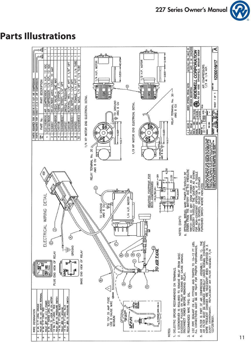
11 Parts Illustrations 11
12 Series Owner s Manual

13 13
14 Series Owner s Manual

15 Common replacement parts are shown below. For air springs, hangers, and torque beams, refer to your specific installation drawing. NOTE: This new style eccentric bolt replaces previous style with square head. 15

TECHNICAL BULLETIN. Meritor WABCO Cab Leveling Valves and Chassis Leveling Valves. How the Cab Leveling and Chassis Leveling Valves Work
 Revised 02-00 TECHNICAL BULLETIN Meritor WABCO Cab Leveling Valves and Chassis Leveling Valves This technical bulletin covers both cab and chassis leveling valves manufactured by Meritor WABCO. While the
MEASURING WHEEL ALIGNMENT
 MEASURING WHEEL ALIGNMENT 2003-04 WHEEL ALIGNMENT Specifications & Procedures - Hummer - H2 Steering and vibration complaints are not always the result of improper alignment. One possible cause is wheel
SELF-STEERING AXLE TABLE OF CONTENTS
 SELF-STEERING AXLE TABLE OF CONTENTS Section 1 - Introduction Section 2 - Pre-Installation Check List Section 3 - Ride Height Adjustments Section 4 - Suspension Mount Section 5 - Axle Mount Section 6 -
INSTALLATION INSTRUCTIONS. 6108 Air Spring Kit 2011+ Ford F250 Single Wheel 4WD 2011+ Ford F350 Dually 4WD (2011 F350 Single Wheel 4WD use p/n 6113)
") INSTALLATION INSTRUCTIONS 6108 Air Spring Kit 2011+ Ford F250 Single Wheel 4WD 2011+ Ford F350 Dually 4WD (2011 F350 Single Wheel 4WD use p/n 6113) Thank you for purchasing a quality Hellwig Product. PLEASE
INSTALLATION INSTRUCTIONS 6108 Air Spring Kit 2011+ Ford F250 Single Wheel 4WD 2011+ Ford F350 Dually 4WD (2011 F350 Single Wheel 4WD use p/n 6113) Thank you for purchasing a quality Hellwig Product. PLEASE
1993 SUSPENSION Volkswagen Front. EuroVan
 Article Text ARTICLE BEGINNING 1993 SUSPENSION Volkswagen Front EuroVan DESCRIPTION FWD independent suspension is an double-wishbone type with torsion bars mounted on upper control arm. Wheel is supported
INSTALLATION INSTRUCTIONS. 6111 Air Spring Kit 2011+ Ford F250/F-350 Single Wheel 2WD 2011+ Ford F350 Dually 2WD IMPORTANT NOTES
 INSTALLATION INSTRUCTIONS 6111 Air Spring Kit 2011+ Ford F250/F-350 Single Wheel 2WD 2011+ Ford F350 Dually 2WD Thank you for purchasing a quality Hellwig Product. PLEASE READ THIS INSTRUCTION SHEET COMPLETELY
2011-14 F250 6 RADIUS ARM KIT
 92154000 Thank you for choosing Rough Country for your suspension needs. 2011-14 F250 6 RADIUS ARM KIT Rough Country recommends a certified technician installs this system. In addition to these instructions,
READ AND UNDERSTAND ALL INSTRUCTIONS AND WARNINGS PRIOR TO INSTALLATION OF SYSTEM AND OPERATION OF VEHICLE.
 491 W. Garfield Ave., Coldwater, MI 49036 Phone: 517-279-2135 Web/live chat: www.bds-suspension.com E-mail: tech-bds@sporttruckusainc.com Product: GM Leaf Spring READ AND UNDERSTAND ALL INSTRUCTIONS AND
WARNING TO END USER, INSTALLER AND SELLER OF THIS PART!
 WARNING TO END USER, INSTALLER AND SELLER OF THIS PART! By installing this part you are accepting full responsibility and liability for proper wheel and tire fitment after installation. It is the installer
Rating when used as a weight carrying hitch without spring bars:
 BOLT-TOGETHER WEIGHT DISTRIBUTING HITCH SYSTEM Rating when used as a weight distributing hitch with spring bars: Part Number 48051 4805 48053 48054 Max Tongue Weight 550 Ibs. 750 Ibs. 1000 Ibs. 1400 lbs.
Ford F-250 / 350 2-1/2 Coil Kit. Ford F-250, F350 2011-2015. Part#: 013255
 Part#: 013255 Ford F-250 / 350 2-1/2 Coil Kit Ford F-250, F350 2011-2015 Rev.040815 491 W. Garfield Ave., Coldwater, MI 49036. Phone: 517-279-2135 Web/live chat: www.bds-suspension.com. E-mail: tech@bds-suspension.com
LIFT-505. BMF Lift Kit. Yamaha Drive Gas or Electric. Installation Instructions
 LIFT-505 BMF Lift Kit Yamaha Drive Gas or Electric Installation Instructions Contents of LIFT-505 Yamaha Drive BMF Lift Kit: a (1 ea.) BMF A-Arm Assembly b (1 ea.) Driver Side Shock Tower c (1 ea.) Passenger
2003 Audi A4. AUDI' '3.0L V6 - AVK Engine - A4 & A6
 Installation (A4) CAUTION: Before installation, ensure camshafts are aligned, crankshaft is locked in place and camshaft gear bolts are loose as described in removal procedures. When turning camshaft,
Volkswagen B3 Passat Manual Transmission 02A 34 Manual Transmission - Controls, Assembly (Page GR-34) 02A 5-speed. Gearshift cable/lever installing
 02A 5-speed. Gearshift cable/lever installing") 34 Manual Transmission - Controls, Assembly (Page GR-34) 02A 5-speed Gearshift cable/lever installing Gearshift housing repairing Gearshift lever repairing lever/relay lever, installing Gearshift mechanism
34 Manual Transmission - Controls, Assembly (Page GR-34) 02A 5-speed Gearshift cable/lever installing Gearshift housing repairing Gearshift lever repairing lever/relay lever, installing Gearshift mechanism
92-00 Civic/ 94-01 Integra/ 93-97 Del Sol/ 92-95 CRX Rear Kit Part No. 75540
 92-00 Civic/ 94-01 Integra/ 93-97 Del Sol/ 92-95 CRX Rear Kit Part No. 75540 www.airliftperformance.com MN-514 (06409) NPR 4762 Please read these instructions completely before proceeding with installation
STEERING HANDLEBAR/FRONT WHEEL/ FRONT SHOCK ABSORBER
 14 14 STEERING HANDLEBAR/FRONT WHEEL/ SCHEMATIC DRAWING ------------------------------------------------- 14-1 SERVICE INFORMATION------------------------------------------------ 14-2 TROUBLESHOOTING-----------------------------------------------------
WHEEL ALIGNMENT SPECIFICATIONS & PROCEDURES
 WHEEL ALIGNMENT SPECIFICATIONS & PROCEDURES For 1234 1992 WHEEL ALIGNMENT Subaru Specifications & Procedures Justy, Legacy, Loyale, SVX * PLEASE READ THIS FIRST * NOTE: Prior to performing wheel alignment,
Service Manual Rol-Lift
 R 2000 Service Manual Rol-Lift Series: T and E Developed by Generic Parts Service This manual is intended for basic service and maintenance of the Rol-Lift pallet jack. The pallet jacks you are servicing
Installation Guide for the TJ LCG PRO Suspension System (Low Center of Gravity) Available 4 or 5
 Available 4 or 5") INSTALLATION GUIDE Installation Guide for the TJ LCG PRO Suspension System (Low Center of Gravity) Available 4 or 5 Take every precaution to make this installation a safe procedure. Make safety the number
INSTALLATION GUIDE Installation Guide for the TJ LCG PRO Suspension System (Low Center of Gravity) Available 4 or 5 Take every precaution to make this installation a safe procedure. Make safety the number
»Product» Safety Warning
 C1200 Installation Instructions 2007-2016 Chevy/GM 1500 2/4wd 2" Strut Spacer Lift Read and understand all instructions and warnings prior to installation of product and operation of vehicle. Zone Offroad
Table of Contents WARNING SYMBOLS AND DEFINITIONS
 Table of Contents SAFETY INSTALLATION OPERATION MAINTENANCE Safety... 2 Specifications... 4 Installation... 5 Operation... 8 WARNING SYMBOLS AND DEFINITIONS Maintenance... 9 Parts List and Assembly Diagram...
Street-Lynx. Reilly MotorSports, Inc. Installation Manual
 Street-Lynx By Reilly MotorSports, Inc. Installation Manual 1 1- Begin by removing your original rear suspension disconnect your brake lines, E-brake cables, and remove the driveshaft. To prevent fire
Competition 4 & 6 suspension Lift Toyota Landcruiser & nissan patrol
 Competition 4 & 6 suspension Lift Toyota Landcruiser & nissan patrol Competition suspension Product Guidelines Guidelines for sale and recommendation of 4 (100mm) and 6 (150mm) Lifts for Toyota Landcruiser
Freightliner AirLiner Suspension 32.05
 Freightliner irliner Suspension 3.05 Ride Height djustment NOTICE Failure to adjust the suspension ride height could adversely affect driveline angles. lso, if the air springs are set too high, the driver
Owner s Manual Read and keep this manual. Patents World Wide
 Owner s Manual Read and keep this manual. Patents World Wide S & S Industries, Inc., Sarasota, FL, USA www.trail-gator.com Copyright 2008 All Rights Reserved The following manual is provided to assist
Front axle components, overview
 just a test. Front axle components, overview 40-1 General Information Load bearing components and parts of the suspension must not be welded or straightened. Vehicles without drive axle must not be moved,
Section A. GENERAL INFORMATION
 Section A. GENERAL INFORMATION I. Description The information and instructions for attaching the sidecar to the right-hand side of the motorcycle are contained in this handbook and must be carefully observed.
WHEEL ALIGNMENT 4WD SA 6
 SA6 WHEEL ALIGNMENT 4WD 1. MAKE FOLLOWING CHECKS AND CORRECT ANY PROBLEMS (a) Check the tires for wear and proper inflation. Cold tire inflation pressure: See page A25 (b) Check the wheel runout. Lateral
SCION tc 2005-2008 COIL OVER SUSPENSION Preparation
 SCION tc 2005-2008 COIL OVER SUSPENSION Preparation Part Number: PTR11-21070 NOTE: Part number of this accessory may not be the same as the part number shown. Kit Contents: Item # Quantity Reqd. Description
P7100 PUMP INSTALLATION INSTRUCTIONS Diesel Care & Performance Inc
 P7100 PUMP INSTALLATION INSTRUCTIONS Diesel Care & Performance Inc Installation Timing Pin Location CAUTION: Before installing the injection pump, be sure that number 1 cylinder is at the Top Dead Center
HYDRAULIC LIFT TABLE CART 2200-LB.
 HYDRAULIC LIFT TABLE CART 2200-LB. OWNER S MANUAL WARNING: Read carefully and understand all MACHINE ADJUSTMENT AND OPERATION INSTRUCTIONS before operating. Failure to follow the safety rules and other
6 inch A-Arm Lift Kit WARNING: 16-018/16-019. installation instructions. will fit CLUB CAR DS. included:
 Revised May 205 6-08/6-09 6 inch A-Arm Lift Kit will fit CLUB CAR DS installation instructions included: Rear Lift Blocks Main Suspension Assembly Spindles A-Arms Rear Shock Mounting Plates U-Bolts WARNING:
VW Caddy W21-760-3503 INSTALLATION INSTRUCTIONS
 Unit 626 Kilshane Avenue, North West Business Park, Ballycoolin, Dublin 15, Ireland Telephone: +353 1 8612 632, Fax: +353 1 8612 647, email: sales@driveriteltd.com www.driveriteltd.com VW Caddy W21-760-3503
ReadyLift (Part# 66-5075) Strut Extension, Installation Instructions Toyota Tundra New Body Style 2WD & 4WD
 Strut Extension, Installation Instructions Toyota Tundra New Body Style 2WD & 4WD") SAFETY WARNING: recommends this system be installed by a professional technician. In addition to these instructions, professional knowledge of disassembly/ reassembly procedures and post installation checks
SAFETY WARNING: recommends this system be installed by a professional technician. In addition to these instructions, professional knowledge of disassembly/ reassembly procedures and post installation checks
Volkswagen Jetta, Golf, GTI 1999, 2000 Brake System 47 Brakes - Hydraulic Components (Page GR-47)
") 47 Brakes - Hydraulic Components (Page GR-47) FS III front brake calipers, servicing Front brake caliper piston, removing and installing FN 3 front brake calipers, servicing Front caliper piston, removing
47 Brakes - Hydraulic Components (Page GR-47) FS III front brake calipers, servicing Front brake caliper piston, removing and installing FN 3 front brake calipers, servicing Front caliper piston, removing
Pallet Jack. OWNER S MANUAL Model MH1230. Important Safety Instructions Assembly Instructions Parts and Hardware Identification
 OWNER S MANUAL Model MH1230 Important Safety Instructions Assembly Instructions Parts and Hardware Identification Pallet Jack CAUTION: Read, understand and follow ALL instructions before using this product
4.5 LIFT BOX KIT 2009 2013 DODGE RAM 2500 & 3500 4WD DIESEL ENGINE ONLY FTS23031
 4.5 LIFT BOX KIT 2009 2013 DODGE RAM 2500 & 3500 4WD DIESEL ENGINE ONLY FTS23031 Fabtech Motorsports 4331 Eucalyptus Ave. Chino, CA 91710 Tech Line 909-597-7800 Fax 909-597-7185 Web www.fabtechmotorsports.com
Recall R136 Front Lower Ball Joints Check Torque or Replace
 SERVICE DATE /00 Amended /00 TECHNICAL BULLETIN Recall R6 Front Lower Ball Joints Check Torque or Replace MODEL VIN Remove and destroy Bulletin S04-R6, dated /00. Replace with this Bulletin. Revisions
Volkswagen Phaeton 44-2 Wheel and tire mounting Wheel mounting Mounting tires Pressing off tires Dismounting tires Mounting tires
 Wheel and tire mounting Стр. 1 из 1 Volkswagen Phaeton 44-2 Wheel and tire mounting Wheel mounting Wheel bolt to hub Torque specification: 120 Nm Mounting tires The tires are installed as usual, but note
Procedures and Intervals to Inspect the Wheel Ends and Tighten the Spindle Nuts on Meritor TL Series Trailer Axles with Unitized Wheel Ends
 Technical Bulletin Revised 1 Technical 02-11 Bulletin Revised 02-11 Procedures and Intervals to Inspect the Wheel Ends and Tighten the Spindle Nuts on Meritor TL Series Trailer Axles with Unitized Wheel
Volkswagen Jetta, Golf, GTI 1999, 2000 Brake System 46 Brakes - Mechanical Components (Page GR-46)
") 46 Brakes - Mechanical Components (Page GR-46) Front brakes Brake pads, removing and installing Brake pads, removing and installing FN 3 brake caliper, servicing FS III brake caliper, servicing Rear wheel
46 Brakes - Mechanical Components (Page GR-46) Front brakes Brake pads, removing and installing Brake pads, removing and installing FN 3 brake caliper, servicing FS III brake caliper, servicing Rear wheel
INSTALLATION INSTRUCTIONS COMPETITION SERIES COILOVER SUSPENSION SYSTEM 03+ Scion xb
 INSTALLATION INSTRUCTIONS COMPETITION SERIES COILOVER SUSPENSION SYSTEM 03+ Scion xb NOTE: Progress Technology products should only be installed by a qualified licensed mechanic experienced in the installation
Installation manual. 3 suspension system. 2009-2013 Ford F150. Part # 23000. Part # 23000. Important customer information: 2009-2013 Ford F150
 Installation manual 3 suspension system 2009-2013 Ford F150 Part # 23000 sj12112012rev.03 Part # 23000 2009-2013 Ford F150 3 suspension system Part # Description Qty. 23000-01 Driver side upper control
Model Year: 2010 Model: Prius Doc ID: RM000001Y3B015X. Title: ALIGNMENT / HANDLING DIAGNOSIS: FRONT WHEEL ALIGNMENT: ADJUSTMENT (2010 Prius)
") Last Modified: 5-3-2010 6.4 N From: 200904 Model Year: 2010 Model: Prius Doc ID: RM000001Y3B015X Title: ALIGNMENT / HANDLING DIAGNOSIS: FRONT WHEEL ALIGNMENT: ADJUSTMENT (2010 Prius) ADJUSTMENT If the
Last Modified: 5-3-2010 6.4 N From: 200904 Model Year: 2010 Model: Prius Doc ID: RM000001Y3B015X Title: ALIGNMENT / HANDLING DIAGNOSIS: FRONT WHEEL ALIGNMENT: ADJUSTMENT (2010 Prius) ADJUSTMENT If the
TJ Quick Disconnect Instructions
 1 TJ Quick Disconnect Instructions www.teraflex.com Kit #17012 Kit #17092 Kit #17010 Kit #17090 Important Notes: Prior to beginning this or any installation read these instructions to familiarize yourself
COMFORT AIR 190/210/230 Single Axle Rear Air Suspension for Hino Vehicles
 COMFORT AIR 190/210/230 Single Axle Rear Air Suspension for Hino Vehicles SUBJECT: Service Instructions LIT NO: 17730-245 DATE: November 2013 REVISION: B TABLE OF CONTENTS Section 1 Introduction... 2 Section
WHEEL ALIGNMENT SPECIFICATIONS & PROCEDURES
 WHEEL ALIGNMENT SPECIFICATIONS & PROCEDURES 1998 Mitsubishi Montero 1997-98 WHEEL ALIGNMENT Mitsubishi - Specifications & Procedures Diamante, Eclipse, Galant, Mirage, Montero, Montero Sport, 3000GT RIDING
I BEAM TRACK INSTALLATION
 PDQ 0/700 FESTOON SYSTEM INSTALLATION AND MAINTENANCE INSTRUCTIONS INTRODUCTION The PDQ Festoon System was designed to run on one of three sizes of I-beams: S x., S8 x 8. and S x.. System trolleys must
12. REAR WHEEL/BRAKE/SUSPENSION
 12 12 12-0 SERVICE INFORMATION... 12-1 REAR BRAKE... 12-5 TROUBLESHOOTING... 12-2 REAR SHOCK ABSORBER... 12-8 REAR WHEEL... 12-3 REAR FORK... 12-9 SERVICE INFORMATION GENERAL INSTRUCTIONS When installing
Instructions and precautions. Fork Height. Visit our website at: http://www.harborfreight.com
 Pallet Jack Item 68760 / 68761 Instructions and precautions Specifications Capacity Control Lever Fork Height Fork Length Fork Width Maximum Minimum Width over Forks Steering Wheel Dia. 2-1/2 Ton (5,000
Unit: mm(in) Item Standard value Service limit Axle shaft run out - 0.2(0.008)
 Item Standard value Service limit Axle shaft run out - 0.2(0.008)") Rear Wheel/Brake/Suspension 13. Rear Wheel/Brake/Suspension Service Information 13-1 Troubleshooting 13-2 Rear Wheel 13-3 Rear Cushion 13-4 Rear Swing Arm 13-7 Service Information General Safety If the
Rear Wheel/Brake/Suspension 13. Rear Wheel/Brake/Suspension Service Information 13-1 Troubleshooting 13-2 Rear Wheel 13-3 Rear Cushion 13-4 Rear Swing Arm 13-7 Service Information General Safety If the
OPERATING and MAINTENANCE MANUAL SERIES 2700A CONTROL VALVE CONTENTS. INTRODUCTION...1 Scope...1 Description...1 Valve Identification...
 OPERATING and MAINTENANCE MANUAL SERIES 2700A CONTROL VALVE CONTENTS INTRODUCTION...1 Scope...1 Description...1 Valve Identification...2 1.0 VALVE INSTALLATION...2 2.0 VALVE MAINTENANCE...3 Actuator Disassembly...3
Overview PARTS LIST. B. Lever mounting base C. Flush handle assembly D. Grey/Blue float stop E. Grey float (Full Flush) F. Flush valve washer
 F. Flush valve washer") Overview READ ENTIRE INSTRUCTIONS BEFORE STARTING INSTALLATION PARTS LIST A. Flush valve B. Lever mounting base C. Flush handle assembly D. Grey/Blue float stop E. Grey float (Full Flush) F. Flush valve
Overview READ ENTIRE INSTRUCTIONS BEFORE STARTING INSTALLATION PARTS LIST A. Flush valve B. Lever mounting base C. Flush handle assembly D. Grey/Blue float stop E. Grey float (Full Flush) F. Flush valve
16 April 2012 1032011-F 1994-2002 Dodge Adjustable Track bar with Relocation Bracket 1
 16 April 2012 1032011-F 1994-2002 Dodge Adjustable Track bar with Relocation Bracket 1 BD Adjustable Track Bar w/bracket Dodge 2500-3500 4WD Models 1994-2002 Dodge 1500 4WD Model 1994-2001 P/N# 1032011-F
Turbocharger system components, servicing
 21-1 Turbocharger system components, servicing Engine codes: AAZ, 1Z, AHU Observe rules of cleanliness Page 21-10 Turbocharger hoses and lines, connecting Page 21-11 WARNING! Do not re-use any fasteners
Class 5 to 7 Truck and Bus Hydraulic Brake System
 Class 5 to 7 Truck and Bus Hydraulic Brake System Diagnostic Guide 1st Edition * 5+0 Important Service tes The information in this publication was current at the time of printing. The information presented
SureSite Magnetic Liquid Level Indicator
 SureSite Magnetic Liquid Level Indicator Instruction Bulletin No. 177664-1 (Rev. E) Section 1: Weldments Thank you for purchasing the GEMS SureSite Magnetic Level Indicator. Please read this document prior
Important: Please read these instructions carefully and completely before starting the installation. TITAN Fuel Tanks
 TITAN pt. no.: 03 0000 0120 Important: Please read these instructions carefully and completely before starting the installation. TITAN Fuel Tanks INSTALLATION INSTRUCTIONS G e n e r a t i o n V Extended
Oregon Fuel Injection
 Corporate Office: P.O. Box 21121, VE Pump Removal and Installation Cummins Lock Timed Applications Removal Clean the exterior of the injection pump and mounting surfaces. 1. Disconnect the fuel return
S-Cam Air Brakes. Braking Systems - Air. Operation
 Operation S-Cam Air Brakes Trailer air brakes are operated by the tractor air supply through a series of relay and check valves. When braking is desired, the air is supplied to the axle air chamber which
Check for deteriorated, shifting or missing tie-down pads. Replace if needed.
 C C 0 5 C H A S S I S F R A M E Chassis Frame Overview The Blue Bird Vision s chassis frame consists of two main C-channel rails which run the entire length of the bus, and several different kinds of cross
13. REAR WHEEL/BRAKE/SUSPENSION
 13. REAR WHEEL/BRAKE/SUSPENSION 13 3.5~4.5kg-m 8.0~10.0kg-m 0.8~1.2kg-m 3.0~4.0kg-m 2.4~3.0kg-m 3.5~4.5kg-m 6.0~8.0kg-m 13-0 13. REAR WHEEL/BRAKE/SUSPENSION 13 REAR WHEEL/BRAKE/SUSPENSION SERVICE INFORMATION...
DYNA RIDER FOOTBOARD KIT
 -J0 REV. 0-0-0 DYNA RIDER FOOTBOARD KIT GENERAL Kit Number 000 Models For model fitment information, see the P&A Retail Catalog or the Parts and Accessories section of www.harley-davidson.com (English
Cylinder head, removing and replacing
 15-1 Cylinder head, removing and replacing WARNING! Do not re-use any fasteners that are worn or deformed in normal use. Some fasteners are designed to be used only once, and are unreliable and may fail
Trouble Shooting Tech Tips Operation
 Steering Components TroubleShooting Tech Tips Table of Contents Basic Steering System Operation 2 Sector Shaft Adjustments 4 Drag Link Adjustment 5 Relief Valve/Unloading Valve Adjustment 6 Ross TAS Automatic
PRIMAAX EX / PRIMAAX Rear Air Suspension for Mack Vehicles
 PRIMAAX EX / PRIMAAX Rear Air Suspension for Mack Vehicles LIT NO: SP-231 DATE: June 2014 REVISION: D PRIMAAX EX for Mack Vehicles with Drum Brakes 8.5" / 10.0" Ride Height Drum Brakes 31 29 30 18 32 27
STEERING SYSTEM - POWER
 STEERING SYSTEM - POWER 1990 Nissan 240SX 1990 STEERING Nissan - Power Rack & Pinion Axxess, Maxima, Pulsar NX, Sentra, Stanza, 240SX, 300ZX DESCRIPTION The power steering system consists of a rack and
DETACHABLE WINDSHIELD AND DOCKING HARDWARE KIT
 -J00 REV. 00-- DETACHABLE WINDSHIELD AND DOCKING HARDWARE KIT GENERAL Kit Number -A, 0-, -, 0-, -, - 0, -0 Models These kits fit and later FXST, FXSTB, FXSTC, and and later FXDWG Harley-Davidson model
SECTION G2: CABLE PROCESSOR MODULE MAINTENANCE
 SECTION G2: CABLE PROCESSOR MODULE MAINTENANCE Cable Processor Module overview WARNING! When tipping the Cable Processor Module back, (after removing the toggle arm pin), use extreme caution not to drop
SUSPENSION 2-1 SUSPENSION TABLE OF CONTENTS
 PL SUSPENSION 2-1 SUSPENSION TABLE OF CONTENTS page WHEEL ALIGNMENT... 1 FRONT SUSPENSION... 9 page REAR SUSPENSION... 35 WHEEL ALIGNMENT TABLE OF CONTENTS page DESCRIPTION AND OPERATION WHEEL ALIGNMENT...1
Spicer Axles & Brakes ABIB-0302
 Information Bulletin Bulletin Type: Parts / Service Information Topic: Dana LMS Hub Assembly Procedure Steer and Drive Axles Spicer Axles & Brakes ABIB-0302 Note: Bulletin ABIB-0302 replaces the original
HOME GYM. Model. Retain This Manual for Reference OWNER'S MANUAL. www.hyper-extension.com
 NOTE: Please read all instructions carefully before using this product Table of Contents Safety Notice www.hyper-extension.com HOME GYM 50036 Hardware Identifier Assembly Instruction Parts List Warranty
R O A D M A S T E R, I N C.
 R O A D M A S T E R, I N C. ROADMASTER, Inc. 6110 NE 127th Ave. Vancouver, WA 98682 8 7 1 6 15 28 1 2 "± 1 2 " MOUNTING BRACKET KIT 3 2 10 14 4 5 9 360-896-0407 fax 360-735-9300 www.roadmasterinc.com Item
2740 Whitten Rd Bldg 103 Memphis, TN 38133 Telephone 901-380-9290 Email Bwilliams@Dieselcare.net
 Fuel Injection Pump Replacement REMOVAL Diesel Care & Performance Inc 1. Disconnect negative battery terminal. 2. Remove throttle linkage. Fuel Injection Pump Bracket 3. Remove injection pump bracket.
MODEL G300 BRAKE BLEEDER
 MODEL G300 BRAKE BLEEDER Installation, Operation & Repair Parts Information Branick Industries, Inc. 4245 Main Avenue P.O. Box 1937 Fargo, North Dakota 58103 REV060616 P/N: 81-0035G 1 THIS PAGE INTENTIONALLY
Service Bulletin Trucks Date Group No. Page
 Volvo Trucks North America, Inc. Greensboro, NC USA Replaces Service Bulletin 601 06 dated 03.98. Service Bulletin Trucks Date Group No. Page 9.2000 601 006 1(8) Wheel Alignment Steer and Drive Axles VN,
DANGER DANGER. General Information. Safety Is Your Responsibility. Ordering Parts. Contact Information
 Safety Safety Is Your Responsibility DANGER To avoid personal injury or death, carefully read and understand all instructions pertaining to the Anthony Liftgates product. Do not attempt to install, operate,
FLUSHOMETER - TANK SYSTEM
 Owner s Service Manual 501-A Series FLUSHOMETER - TANK SYSTEM 501-A Series FLUSHMATE 501-A SERIES (D) (E) (C) 2 3 (B) 1 4 (F) (A) 6 5 List of Components for 501-A Series*: 1. Lower Supply Group w/hose
R O A D M A S T E R, I N C.
 R O A D M A S T E R, I N C. MOUNTING BRACKET KIT 12 3 6 9 5 11 ITEM QTY NAME MATERIAL 1...4...1/2" x 1 1/2" BOLT... 350095-00 2...4...1/2" x 1 1/2" CARRIAGE BOLT... 350362-00 3...8...1/2" NUT... 350258-00
R O A D M A S T E R, I N C.
 R O A D M A S T E R, I N C. MOUNTING BRACKET KIT 14 8 7 4 13 5 6 ITEM QTY NAME MATERIAL 1...6...1/2" x 2 1/2" BOLT... 350099-00 2...2...1/2" x 1 1/2" BOLT... 350095-00 3...8...1/2" LOCK WASHER... 350309-00
R O A D M A S T E R, I N C.
 R O A D M A S T E R, I N C. ROADMASTER, Inc. 6110 NE 127th Ave. Vancouver, WA 98682 12 10 3 11 4 5 13 7 8 360-896-0407 fax 360-735-9300 www.roadmasterinc.com ITEM QTY NAME MATERIAL 1... 4...1/2 x 1 1/2
R O A D M A S T E R, I N C.
 R O A D M A S T E R, I N C. ROADMASTER, Inc. 6110 NE 127th Ave. Vancouver, WA 98682 6 13 11 MOUNTING BRACKET KIT Cable Tab 14 12 7 15 9 Cable Tab 360-896-0407 fax 360-735-9300 www.roadmasterinc.com ITEM
R O A D M A S T E R, I N C.
 R O A D M A S T E R, I N C. 11 10 20 12 4 18 19 1 2 13 16 ITEM QTY NAME MATERIAL 1...2... 1/2" x 3 1/2" BOLT... 350103-00 2...2... 1/2" x 2" BOLT... 350097-00 3...6... 1/2" x 1 1/2" BOLT... 350095-00 4...2...
FRONT SUSPENSION Click on the applicable bookmark to selected the required model year
 FRONT SUSPENSION 33A-2 FRONT SUSPENSION General Information GENERAL INFORMATION 33200010105 The front suspension on 2WD vehicles is an independent suspension system having the double wishbone combined
PALLET JACK - 2.5 TON
 PALLET JACK - 2.5 TON 39939 SET UP AND OPERATING INSTRUCTIONS Visit our website at: http://www.harborfreight.com Read this material before using this product. Failure to do so can result in serious injury.
Front brakes (FN- 3), servicing
, servicing") j a t Front brakes (FN- 3), servicing 46-1 Front brakes, servicing Note: Install complete repair kit. After replacing brake pads and before moving vehicle, depress brake pedal several times firmly to properly
j a t Front brakes (FN- 3), servicing 46-1 Front brakes, servicing Note: Install complete repair kit. After replacing brake pads and before moving vehicle, depress brake pedal several times firmly to properly
1000-LB. TRAILER JACK OWNER S MANUAL
 1000-LB. TRAILER JACK OWNER S MANUAL WARNING: Read carefully and understand all INSTRUCTIONS before operating. Failure to follow the safety rules and other basic safety precautions may result in serious
88-98 Chevy / GMC Fullsize 4WD 6-Lug 2"- 2 1/2" Suspension Lift Installation Instructions
 88-98 Chevy / GMC Fullsize 4WD 6-Lug 2"- 2 1/2" Suspension Lift Installation Instructions Safety Glasses Metric / Standard Wrenches & Sockets Floor Jack Jack Stands Hack Saw Ball Joint Seperator Measuring
GPS AutoSteer System Installation Manual
 GPS AutoSteer System Installation Manual Supported Vehicles John Deere Sprayers 4720 4630 4730 4830 AutoTrac Ready PN: 602-0227-01-A LEGAL DISCLAIMER Note: Read and follow ALL instructions in this manual
Sport Ice Elektro 124
 Sport Ice Elektro 124 Operation Manual 2007/4 V2.1 Introduction The Sport Ice Elektro 124 is an ice resurfacing machine designed to be used on small ice surfaces. The machine has been designed to produce
VT SERIES. Owners Manual VARIABLE TRAVEL MOUNTAIN BIKE
 VT SERIES Owners Manual VARIABLE TRAVEL MOUNTAIN BIKE Multi purpose, Enduro, Trail ride, Light Freeride mountain bike Single pivot, linkage operated rear shock rear suspension Manitou Swinger SPV Air rear
Tri-Homo Style Operation and Maintenance Instructions
 Tri-Homo Style Operation and Maintenance Instructions One Research Drive Stratford, CT 06615 (203) 375-0063 www.sonicmixing.com 1 Installation and Start-up Do not perform following adjustments without
MUSTANG II IFS COMPLETE PARTS PACKAGE
 MUSTANG II IFS COMPLETE PARTS PACKAGE Your Southern Rods & Parts Mustang II IFS Parts Package contains the following items: 1 pr) Upper Control Arms (2023) 1) Upper Arm Bolt Kit (MP-001-A) 1 pr) Lower
Installation manual. 4 suspension system. 2014-2016 Chevy or GMC 1500 4WD. Part # 14059. Part # 14059. Important customer information:
 Installation manual 4 suspension system 2014-2016 Chevy or GMC 1500 4WD Part # 14059 sj09052013rev.01 Part # 14059 2014-2016 Chevy or GMC 1500 4WD 4 suspension system Part # Description Qty. 14056-01 Upper
DM-PD0001-00. (English) Dealer's Manual PD-MX80
 Dealer's Manual PD-MX80") (English) DM-PD0001-00 PD-MX80 Dealer's Manual IMPORTANT NOTICE This dealer s manual is intended primarily for use by professional bicycle mechanics. Users who are not professionally trained for bicycle
(English) DM-PD0001-00 PD-MX80 Dealer's Manual IMPORTANT NOTICE This dealer s manual is intended primarily for use by professional bicycle mechanics. Users who are not professionally trained for bicycle
DO NOT attempt to repair hub and wheel bearing assembly.
 Page 1 of 6 HUB & WHEEL BEARINGS (WITH PULSE VACUUM HUBLOCK) DO NOT attempt to repair hub and wheel bearing assembly. Removal DO NOT remove hub lock assembly by prying on hub lock legs. This can crack
Slide the new steering column shaft through the steering column from the driver compartment.
 Slide the new steering column shaft through the steering column from the driver compartment. Push the column shaft through the steering column until the machined end is out past the column lower bushing.
HYDRAULIC TABLE CART 500-LB.
 HYDRAULIC TABLE CART 500-LB. OWNER S MANUAL WARNING: Read carefully and understand all MACHINE ADJUSTMENT AND OPERATION INSTRUCTIONS before operating. Failure to follow the safety rules and other basic
DeZURIK 3-20" BAW AWWA BUTTERFLY VALVES WITH TRANSFER MOLDED SEAT
 3-20" BAW AWWA BUTTERFLY VALVES WITH TRANSFER MOLDED SEAT Instruction D10386 August 2013 Instructions These instructions provide installation, operation and maintenance information for BAW Butterfly Valves.
SUSPENSION DIAGNOSIS
 SECTION 2A SUSPENSION DIAGNOSIS TABLE OF CONTENTS Diagnosis... 2A-2 General Diagnosis... 2A-2 Hub and Bearing... 2A-7 2A-2 SUSPENSION DIAGNOSIS DIAGNOSIS GENERAL DIAGNOSIS Problems in the steering, the