High Temperature Gas Reactors
|
|
|
- Sybil Nelson
- 7 years ago
- Views:
Transcription
1 High Temperature Gas Reactors Andrew C. Kadak, Ph.D. Professor of the Practice Massachusetts Institute of Technology

2

3
4

5 Presentation Overview Introduction to Gas Reactors Pebble Bed Reactor Players International Status Research Needs

6 Fundamentals of Technology Use of Brayton vs. Rankine Cycle High Temperature Helium Gas (900 C) Direct or Indirect Cycle Originally Used Steam Generators Advanced Designs Use Helium w/wo HXs High Efficiency (45% - 50%) Microsphere Coated Particle Fuel
")
7 History of Gas Reactors in US Peach Bottom (40 MWe) First Commercial (U/Thorium Cycle) - Generally Good Performance (75% CF) Fort St. Vrain ( 330 MWe) (U/Th) - Poor Performance - Mechanical Problems - Decommissioned
 1979-1989 (U/Th) - Poor Performance -")
8 Fort St. Vrain

9 Different Types of Gas Reactors Prismatic (Block) - General Atomics - Fuel Compacts in Graphite Blocks Pebble Bed - German Technology - Fuel in Billiard Ball sized spheres Direct Cycle Indirect Cycle Small Modular vs. Large Reactors

10 GT-MHR Module General Arrangement

11 GT-MHR Combines Meltdown-Proof Advanced Reactor and Gas Turbine

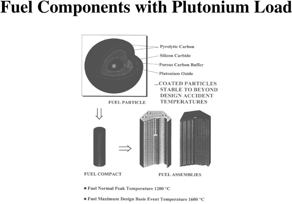
12 TRISO Fuel Particle -- Microsphere Fuel Pebble (60mm) Matrix Graphite Microspheres Microsphere (0.9mm) 0.9mm diameter ~ 11,000 in every pebble 10 9 microspheres in core Fission products retained inside microsphere TRISO acts as a pressure vessel Reliability Defective coatings during manufacture ~ 1 defect in every fuel pebble

13 Fuel Components with Plutonium Load
14 Comparison of 450 MWt and 600 MWt Cores

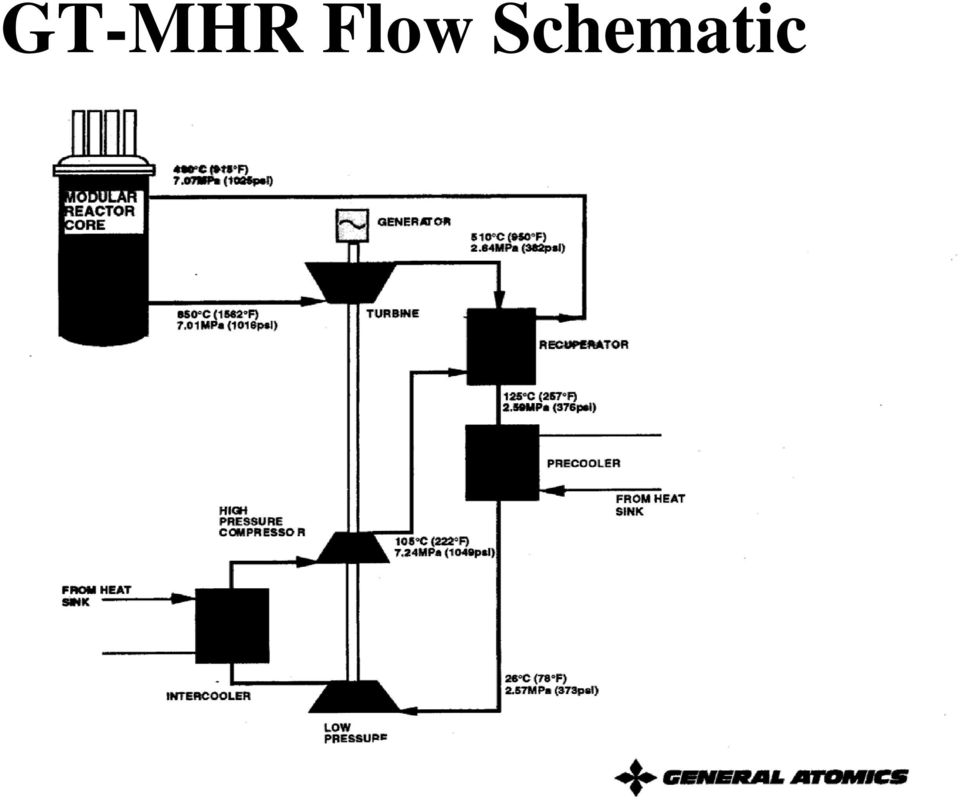
15 GT-MHR Flow Schematic
16 Flow through Power Conversion Vessel

17 Modular Pebble Bed Reactor South Africa - ESKOM

18 FUEL ELEMENT DESIGN FOR PBMR 5mm Graphite layer Coated particles imbedded in Graphite Matrix Dia. 60mm Fuel Sphere Pyrolytic Carbon 40/1000mm Silicon Carbite Barrier Coating Inner Pyrolytic Carbon 40/1000mm Porous Carbon Buffer 95/1000mm 35/1000 Half Section Dia. 0,92mm Coated Particle Dia.0,5mm Uranium Dioxide Fuel

19 Differences Between LWRS Higher Thermal Efficiencies Possible Helium inert gas Minimizes use of water in cycle - corrosion Single Phase coolant fewer problems in accident Utilizes gas turbine technology Lower Power Density no meltdown potential Less Complicated Design (No ECCS)

20 Advantages & Disadvantages Advantages Higher Efficiency Lower operating waste Higher Safety Margins High Burnup MWD/kg Disadvantages Poor History in US Little Helium Turbine Experience US Technology Water Based Licensing Hurdles due to different designs

21 What is a Pebble Bed Reactor? 360,000 pebbles in core about 3,000 pebbles handled by FHS each day about 350 discarded daily one pebble discharged every 30 seconds average pebble cycles through core 10 times Fuel handling most maintenance-intensive part of plant
22
23 HTR- 10 China First Criticality Dec.1, 2000
24
25 Reactor Unit Helium Flowpath
26 Fuel Handling & Storage System Fuel Return Graphite Return Fresh Fuel Container Damaged Sphere Container Fuel/Graphite Discrimination system Spent Fuel Tank
27 Pebble Bed Reactor Designs PBMR (ESKOM) South African - Direct Cycle China Indirect He/Steam Cycle MIT Design - Indirect Cycle - Intermediate He/He HX - Modular Components - site assembly
28 MIT Project Overview Fuel Performance Fission Product Barrier (silver migration) Core Physics Safety Loss of Coolant Air Ingress Balance of Plant Design Modularity Design Intermediate Heat Exchanger Design Core Power Distribution Monitoring Pebble Flow Experiments Non-Proliferation Safeguards Waste Disposal Reactor Research/ Demonstration Facility License by Test Expert I&C System - Hands free operation
29 Safety Issues Fuel Performance - Key to safety case Air Ingress Water Ingress Loss of Coolant Accident Seismic reactivity insertion Reactor Cavity Heat Removal Redundant Shutdown System Silver and Cesium diffusion
30 Safety Advantages Low Power Density Naturally Safe No melt down No significant radiation release in accident Demonstrate with actual test of reactor
31 Naturally Safe Fuel Shut Off All Cooling Withdraw All Control Rods No Emergency Cooling No Operator Action
32 Temperature Profile Fig-10: The Temperature Profile in the 73rd Day Temperature (C) Concrete Wall Core Reflector Cavity Soil 400 Vessel Distance to the Central Line
33 Simplified HEATING7 Open Cylinder Analysis Peak Temperature Figure 3: The peak temperature Temperature (C) time(hr)
34 The Prediction of the Air Velocity (By Dr. H. C. No) Temperature (C) Fig-14: Trends of maximum temperature for 0, 2, 4, 6 m/s of air velocity in the air gap region Time (hr) Hot-Point Temperature of the core(0m/s) Hot-Point Temperature of the Vessel (0m/s) Hot-Point Temperature of the Concrete Wall (0m/s) Hot-Point Temperature of the Core (2m/s) Hot-Point Temperature of the Vessel (2m/s) Hot-Point Temperature of the Concrete Wall (2m/s) Hot-Point Temperature of the Core (6m/s) Hot-Point Temperature of the Vessel (6m/s) Hot-Point Temperature of the Concrete Wall (6m/s) Limiting Temperature for the Vessel Limiting Temperature for the Containment
35 Fuel Performance Model Detailed modeling of fuel kernel Microsphere Monte Carlo Sampling of Properties Use of Real Reactor Power Histories Fracture Mechanics Based Considers Creep, stress, strains, fission product gases, irradiation and temperature dependent properties.
36 TIM Code Model Fuel Performance Code Deals Explicitly With Statistical Nature of Fuel Characteristics, Materials Properties Uncertainty, and Power History Uncertainty (Fueling Scheme in PBMR) Using Monte Carlo Techniques. Advanced Fracture Mechanics Model for PyC and SiC Failure. Able to Model Prismatic as well as Pebble Bed Cores Results Compare Well With Irradiation Experiments Chemical Model-In Progress
37 Fuel Optimization Criteria Considered Fuel Failure Mechanisms Over-pressurization failure by tensile stress Crack-in-pyrocarbon induced failure by stress concentration Fuel Optimization Criteria Minimize the maximum stresses in IPyC and OPyC layers Maximize the gap between Weibull strength and maximum stress for IPyC and OPyC layers Keep the maximum stress in SiC layer non-positive
38 Barrier Integrity Silver leakage observed in temps Experiments Proceeding with Clear Objective - Understand phenomenon Palladium Attack Experiments Underway Zirconium Carbide being tested as a reference against SiC. Focus on Grain SiC Structure Effect Will update model with this information
39 2.0 Ion Implantation Silver Depth Profile Predicted Profile Sample 2b 1.8 Ag as implanted 1.6 Ag after 210 hr heat 2b 2a Atomic Concentration (%) No silver movement after 210 hr at 1500 C Depth (µm)
40 Core Physics Basic tool Very Special Old Programs (VSOP) Developed MNCP Modeling Process Tested Against HTR-10 Benchmark Tested Against ASTRA Tests with South African Fuel and Annular Core VSOP Verification and Validation Effort
41 MCNP4B Modeling of Pebble Bed Reactors Steps in Method Development PROTEUS critical PSI HTR-10 physics benchmark ASTRA critical KI PBMR South Africa simple cores stochastic packing predict criticality cf. measurement mockup of PBMR annular core startup core MCNP vs. VSOP MIT Nuclear Engineering Department 4
42 HTR-10 (Beijing) 10 MW Pebble Bed Reactor: Graphite reflector Core: R c = 90 cm, H 197 cm TRISO fuel with 5 g U/Fuel Sphere 17% U235 F/M sphere ratio = 57:43, modeled by reducing moderator sphere size Initial criticality December 2000 MCNP4B Results K-eff Critical Height Calculated Loading Actual Loading ± cm 16,830 16,890 MIT Nuclear Engineering Department 9
43 Air Ingress Most severe accidents among PBMR s conceivable accidents with a low occurrence frequency. Challenges: Complex geometry, Natural Convection, Diffusion, Chemical Reactions Air/COx out Air In Vary Choke Flow Bottom Reflector
44 The Characteristics the Accident Important parameters governing these reactions Graphite temperature Partial pressures of the oxygen Velocity of the gases Three Stages: Depressurization (10 to 200 hours) Molecular diffusion. Natural circulation
45 Critical Parameters for Air Ingress Temperature of reacting components The concentration of oxygen Gas flow rates Pressure (partial pressure and total pressure in the system)
46 Air Ingress Velocity f(temperature) Fig-2: Air Inlet Velocity Vs. the Average Temp. of the Gases Air Inlet Velocity (m/s) the Average Temp. of the Gases (C)
47 Multi-Component experiment Japanese Air Ingress Tests
48 Multi-Component Experiment Mole Fraction O2(Experiment) O2(Calculation) CO(Experiment) CO(Calculation) CO2(Experiment) CO2(Calculation) Time(min) Figure 36: Mole Fraction at Point-1 (80% Diffusion Coff.)
49 Multi-Component Experiment(Cont.) 0.24 Mole Fraction O2(Experiment) O2(Calculation) CO(Experiment) CO(Calculation) CO2(Experiment) CO2(Calculation) Time(min) Figure 37: Mole Fraction at Point-3
50 Mole Fraction Multi-Component Experiment(Cont.) O2(Experiment) O2(Calculation) CO(Experiment) CO(Calculation) CO2(Experiment) CO2(Calculation) Time (min) Figure 38: Mole Fraction at Point-4
51 NACOK Natural Convection Experiments Figure 39: NACOK Experiment
52 Boundary Conditions Figure 41: Temperature Profile for one experiment
53 The Mass Flow Rates 5.0E E-03 Mass Flow Rate (kg/s ) 3.0E E E E+00 T_R=200 DC(Exp.) T_R=400 DC(Exp.) T_R=600 DC(Exp.) T_R=800 DC(Exp.) T_R=200 DC(FLUENT) T_R=400 DC(FLUENT) T_R=600 DC(FLUENT) T_R=800 DC(FLUENT) Temperature of the Pebble Bed (C) Figure 42: Mass Flow Rates for the NACOK Experiment
54 Future NACOK Tests Blind Benchmark using MIT methodology to reproduce recent tests. Update models Expectation to have a validated model to be used with system codes such as RELAP and INL Melcor.
55 Preliminary Conclusions Air Ingress For an open cylinder of pebbles: Due to the very high resistance through the pebble bed, the inlet air velocity will not exceed 0.08 m/s. The negative feedback: the Air inlet velocity is not always increase when the core is heated up. It reaches its peak value at 300 C. Preliminary combined chemical and chimney effect analysis completed - peak temperatures about 1670 C.
56 Overall Safety Performance Demonstration and Validation China s HTR-10 provides an excellent test bed for validation of fundamentals of reactor performance and safety. Japan s HTTR provides a similar platform for block reactors. Germany s NACOK facility vital for understanding of air ingress events for both types. PBMR s Helium Test Facility, Heat Transfer Test Facility, Fuel Irradiation Tests, PCU Test Model. Needed - open sharing of important technical details to allow for validation and common understanding.
57 Chinese HTR-10 Safety Loss of flow test Shut off circulator Demonstration Restrict Control Rods from Shutting down reactor Isolate Steam Generator - no direct core heat removal only but vessel conduction to reactor cavity
58 Video of Similar Test
59 Loss of Cooling Test Power
60 Loss of Cooling Test Power
61 International Activities Countries with Active HTGR Programs China - 10 MWth Pebble Bed critical Japan - 40 MWth Prismatic South Africa MWth Pebble Russia MWe - Pu Burner Prismatic 2007 (GA, Framatome, DOE, etc) Netherlands - small industrial Pebble Germany (past) MWe Pebble Operated MIT MWth - Intermediate Heat Exch.
62 Pebble Bed Modular Reactor South Africa 165 MWe Pebble Bed Plant - ESKOM Direct Helium High Temperature Cycle In Licensing Process Schedule for construction start 2007 Operation Date 2011/12 Commercial Reference Plant
63 South Africa Demonstration Plant Status Koeberg site on Western Cape selected Designated national strategic project in May 2003 Environmental Impact Assessment (EIA) completed with positive record of decision; appeals to be dispositioned by December 2004 Revised Safety Analysis Report in preparation; to be submitted to National Nuclear Regulator in January 2006 Construction scheduled to start April 2007 with initial operation in 2010 Project restructuring ongoing with new investors and new governance
64 Commercial Plant Target Specifications Rated Power per Module MW(e) depending on injection temperature Eight-pack Plant 1320 MW(e) Module Construction 24 months (1st) Schedule Planned Outages 30 days per 6 years Fuel Costs & O&M Costs < 9 mills/kwh Availability >95%
65 Modular High Temperature Gas Reactor Russia General Atomics Design 290 MWe - Prismatic Core Excess Weapons Plutonium Burner In Design Phase in Russia Direct Cycle Start of Construction Depends on US Gov Funding maybe never
66 High Temperature Test Reactor Japan 40 MWth Test Reactor First Critical 1999 Prismatic Core Intermediate Heat Exchangers Reached full power and 950 C for short time
67 High Temperature Test Reactor
68
69
70 High Temperature Reactor China 10 MWth - 4 MWe Electric Pebble Bed Initial Criticality Dec 2000 Intermediate Heat Exchanger - Steam Cycle Using to as test reactor for full scale demonstration plant HTR-PM
71 HTR- 10 China First Criticality Dec.1, 2000
72
73
74
75 China is Focused Formed company Chinergy Owned by Institute of Nuclear Energy Technology of Tsinghua University and China Nuclear Engineering Company (50/50) Customer Huaneng Group largest utility Two Sites selected evaluating now Target commercial operation 2010/2011
76 France AREVA - Framatome
77 MIT s Pebble Bed Project Similar in Concept to ESKOM Developed Independently Indirect Gas Cycle Costs 3.3 c/kwhr High Automation License by Test
78 Modular High Temperature Pebble Bed Reactor 120 MWe Helium Cooled 8 % Enriched Fuel Built in 2 Years Factory Built Site Assembled On--line Refueling Modules added to meet demand. No Reprocessing High Burnup >90,000 Mwd/MT Direct Disposal of HLW Process Heat Applications - Hydrogen, water
79 MIT MPBR Specifications Thermal Power 250 MW Mwe Target Thermal Efficiency 45 % Core Height 10.0 m Core Diameter 3.5 m Pressure Vessel Height 16 m Pressure Vessel Radius 5.6 m Number of Fuel Pebbles 360,000 Microspheres/Fuel Pebble 11,000 Fuel UO 2 Fuel Pebble Diameter 60 mm Fuel Pebble enrichment 8% Uranium Mass/Fuel Pebble 7 g Coolant Helium Helium mass flow rate 120 kg/s (100% power) Helium entry/exit temperatures 450 o C/850 o C Helium pressure 80 bar Mean Power Density 3.54 MW/m 3 Number of Control Rods 6
80 For 1150 MW Combined Heat and Power Station Ten-Unit VHTR Plant Layout (Top View) Equip Access Hatch 7 (distances in meters) Equip Access Hatch Admin Training VHTR Characteristics - Temperatures > 900 C - Indirect Cycle - Core Options Available - Waste Minimization Oil Refinery 10 8 Equip Access 6 Hatch 4 2 Control Bldg. 60 Maintenance Parts / Tools 80 Turbine Hall Boundary Primary island with reactor and IHX Turbomachinery 100 Desalinization Plant Hydrogen Production
81 Reference Plant Modular Pebble Bed Reactor Thermal Power 250 MW Core Height 10.0 m Core Diameter 3.5 m Fuel UO 2 Number of Fuel Pebbles 360,000 Microspheres/Fuel Pebble 11,000 Fuel Pebble Diameter 60 mm Microsphere Diameter ~ 1mm Coolant Helium
82 23.mpg 22.mpg 21.mpg Video Demo 20.mpg 19.mpg
83 Shaping Ring for Central Column Formation Shaping ring used to form central column at top 3 inches Rest open - no ring Column maintained during slow drain down. Bottom of Shaping ring
84 Features of Current Design Thermal Power Gross Electrical Power Net Electrical Power Plant Net Efficiency Helium Mass flowrate Core Outlet/Inlet T Cycle pressure ratio Power conversion unit 250 MW MW MW 48.1% (Not take into account cooling IHX and HPT. if considering, it is believed > 45%) kg/s 900 C/520 C 2.96 Three-shaft Arrangement
85 Indirect Cycle with Intermediate Helium to Helium Heat Exchanger Current Design Schematic 280 C 520 C 126.7kg/s Reactor core 800 C 7.75MPa HPT 52.8MW MPC MW HPC 26.1MW 69.7 C 8.0MPa 900 C C 6.44 MPa Intercooler 7.73MPa IHX 69.7 C 4.67MPa 115 C 1.3kg/s C 7.89MPa 125.4kg/s Cooling RPV C 7.59MPa Circulator 69.7 C 1.3kg/s 350 C 7.90MPa 326 C 105.7kg/s LPT 52.8MW 719. C 5.21MPa PT 136.9MW C 2.75MPa LPC 26.1 MW 30 C 2.71MPa Generator Recuperator MPC1 26.1MW Bypass Valve 96.1 C 2.73MPa Precool er Inventory control
86 Top Down View of Pebble Bed Reactor Plant Reactor Vessel TOP VIEW WHOLE PLANT Plant Footprint IHX Module Recuperator Module HP Turbine Precooler LP Compressor ~77 ft. MP Turbine MP Compressor Turbogenerator LP Turbine Intercooler #1 Intercooler #2 ~70 ft. Power Turbine HP Compressor
87 PLANT MODULE SHIPPING BREAKDOWN Total Modules Needed For Plant Assembly (21): Nine 8x30 Modules, Five 8x40 Modules, Seven 8x20 Modules Six 8x30 IHX Modules Six 8x20 Recuperator Modules 8x30 Power Turbine Module 8x20 Intercooler #2 Module 8x40 Piping and Precooler Module 8x30 Upper Manifold Module 8x30 Lower Manifold Module 8x40 Piping & Intercooler #1 Module 8x40 HP Turbine, LP Compressor Module 8x40 MP Turbine, MP Compressor Module 8x40 LP Turbine, HP Compressor Module
88 Example Plant Layout Secondary (BOP) Side Hall Primary Side Hall Turbomachinery Reactor Vessel Recuperator Modules IHX Modules NOTE: Space-frames and ancillary components not shown for clarity
89 Space Frame Technology for Shipment and Assembly Everything is installed in the volume occupied by the space frame - controls, wiring, instrumentation, pumps, etc. Each space frame will be plugged into the adjacent space frame.
90 Lego Style Assembly in the Field
91 Space-Frame Concept Standardized Frame Size 2.4 x 2.6 x 3(n) Meter Standard Dry Cargo Container Attempt to Limit Module Mass to ~30t / 6m ISO Limit for 6m Container Stacking Load Limit ~190t ISO Container Mass ~2200kg Modified Design for Higher Capacity ~60t / 12m module Overweight Modules Generator ( t) Turbo-Compressor (45t) Avoid Separating Shafts! Heavy Lift Handling Required Dual Module (12m / 60t) Stacking Load Limit Acceptable Dual Module = ~380T Turbo-generator Module <300t Design Frame for Cantilever Loads Enables Modules to be Bridged Space Frames are the structural supports for the components. Only need to build open vault areas for space frame installation - RC & BOP vault Alignment Pins on Module Corners High Accuracy Alignment Enables Flanges to be Simply Bolted Together Standardized Umbilical Locations Bus-Layout of Generic Utilities (data/control)
92 Reactor Vessel Present Layout IHX Vessel High Pressure Turbine Low Pressure Turbine Compressor (4) Power Turbine Recuperator Vessel
93 Main IHX Header Flow Paths
94 Plant With Space Frames
95 Upper IHX Manifold in Spaceframe 3 m 10 m 2.5 m
96 Distributed Production Concept MPBR Inc. Component Design Space-Frame Specification Site and Assembly Specifications Component Fabricator #1 e.g. Turbine Manufacturer Component Fabricator #N e.g. Turbine Manufacturer Management and Operation Assembly Contractor Site Preparation Contractor MPBR Construction Site Labor Component Transportation Design Information
97 Generating Cost PBMR vs. AP600, AP1000, CCGT and Coal (Comparison at 11% IRR for Nuclear Options, 9% for Coal and CCGT 1 ) (All in /kwh) Coal 2 Nat. Gas = 3 AP Th 3400Th PBMR Clean Normal $3.00 $3.50 $4.00 $5.00 Fuel O&M Decommissioning Fuel Cycle _ -_ Total Op Costs Capital Recovery Total All options exclude property taxes 2 Preliminary best case coal options: mine mouth location with $20/ton coal, 90% capacity factor & 10,000 BTU/kWh heat rate 3 Natural gas price in $/million Btu
98 Next Generation Nuclear Plant Hydrogen - Thermo-electric plant MIT Modular Pebble Bed Reactor Secondary HX Hydrogen - Thermo-chemical plant
99 Intermediate Heat Exchanger (IHX) Installed In Hot Pipe for PBMR NGNP Pipes for Intermediate Helium Loop Intermediate Heat Exchanger
100 Hydrogen Mission Modularity Flexibility Hydrogen Plant A Hydrogen Plant B Secondary IHX - Helium to Molten Salt? May use one or more IHX s from base electric plant for H 2
101 Primary Internals (3) Plate Fin Core Modules Core Modules Suspended to accommodate expansion
102 VHTR Migration Path Future Technology Regime >500 MWt >1200 o C Technology Threshold 400 MWt 1200 o C - Optimization of Commercial Margins Current Technology Regime 400 MWt 1000 o C - Advanced Fuel & Performance Model - Control Rods - Graphite Lifetime - RPV and Core Barrel Material 400 MWt 950 o C - Reactor Outlet Pipe Liner - Turbine Blade/Disc Material Development - Material and Component Qualification - Codes and Standards (60 y) 400 MWt 900 o C - Safety Case - IHX Hydrogen Process -Codes and Standards (60 y) - Fuel Performance Model - Demonstration Plant
103 Future Research Activities Build and Test Advanced Plate Fin IHX Design Benchmark new series of NACOK Air Ingress Tests with CFD. Perform Pebble Flow Experiments to Reduce Central Column By-pass Flow Expand Fuel Performance Model to handle rapid transients (rod ejection) Make and Test Advanced Fuel Particles with manufacturing and QA integration
104 Summary Safety advantages of High Temperature Reactors are a significant advantage. Air ingress most challenging to address Fuel performance needs to be demonstrated in operational, transient and accident conditions. Validation of analysis codes is important Materials issues may limit maximum operating temperatures and lifetimes of some components. International cooperation is essential on key safety issues.
105 End of Presentation Back up Slides follow
106 Summary High Temperature Reactors are a viable future nuclear option. NGNP to be the demonstration plant Research to lead to Gen IV VHTR for hydrogen production Small size an advantage to deployment and cost if manufacturing modularity approaches followed.
107 Mechanical Analysis System: IPyC/SiC/OPyC Methods: Analytical or Finite Element Viscoelastic Model Mechanical behavior irradiation-induced dimensional changes (PyC) irradiation-induced creep (PyC) pressurization from fission gases thermal expansion Dimensional changes Creep Pressurization Thermal expansion Stress contributors to IPyC/SiC/OPyC
108 Integrated Fuel Performance Model MC Outer Loop 1,000,000 times Power Distribution in the Reactor Core Sample a pebble/fuel particle MC inner loop Randomly re-circulate the pebble t=t+ t Get power density, neutron flux 10 times MC outer loop: samples fuel particles of statistical characteristics T distribution in the pebble and TRISO Accumulate fast neutron fluence FG release (Kr,Xe) PyC swelling MC inner loop: Mechanical model implements refueling scheme in reactor core Mechanical Stresses Strength Failure model Chemical FP distribution Pd & Ag Y Failed N In reactor core Y N
109 Stress Contributors Low Burnup SiC IPyC Internal Pressure IPyC Irr. Dimensional Change SiC IPyC OPyC Irr. Dimensional Change High Burnup
110 TIMCOAT Failure Model (Simplified) r 4 r 5 r 2 r 3 σ t K I = yσ t (πa) 0.5 a IPyC SiC OPyC
111 Evaluate Stress Concentration in SiC A' r r 3 r 4 r 5 A r' r 2 θ σ t C P θ' a K I IPyC K I SiC IPyC SiC OPyC K SiC I IPyC = K d / a I IPyC + σ SiC πd
112 Modules in the Integrated Model Fission gas release model Thermal model Mechanical analysis Chemical analysis OPyC SiC IPyC Buffer PyC Fuel Kernel Fuel failure model Simulation of refueling Optimization process J. Wang, B. G. Ballinger, H. Maclean, An Integrated Fuel Performance Model for Coated Particle Fuel,
113 Stress Development in a Failed Particle 400 Tangential Stress Distribution in Layers Stress Stress (MPa) IPyC SiC OPyC F = 0.0 F = 0.71 F = F = 0.85 Time Position -800 F = Stress Intensity Factors Radius (um) KI (MPa.um 0.5 ) SiC KIC KI from IPyC KI from OPyC Neutron Fast Fluence (10 21 n/cm 2 )
114 Fuel Particle Types Parameter Design As-Fabricated Design Optimized a As-Fabricated Optimize d b Design Optimized (Widened BAF) c U235 Enrichment (%) 9.6 +/ / / / /- 0.1 Kernel Density (g/cm 3 ) / / / / / Kernel Diameter (µm) 500 +/ / / / / Buffer Density (g/cm 3 ) / / / / / Buffer Thickness (µm) / / / / / IPyC Density (g/cm 3 ) IPyC Thickness (µm) / / / / / OPyC Density (g/cm 3 ) OPyC Thickness (µm) / / / / / IPyC/OPyC BAF / / / / / IPyC/OPyC Strength (MPa.m 3/β ) IPyC/OPyC Weibull Modulus β SiC Thickness (µm) / / / / / SiC Strength (MPa.m 3/β ) SiC Weibull Modulus β SiC Fracture Toughness (MPa.µm 1/2 ) / / / / / a: Optimized nominal values + Design Specified Standard Deviations b: Optimized nominal values + As-fabricated Standard Deviations c: Widened Standard Deviation of PyC BAF0 on Case a
115 Fuel Optimization Results Environment Given Irradiation Temperature: 910 C Particle Dimension Kernel Diameter (upper limit): 600µm Buffer Thickness: 120µm IPyC Thickness (lower limit): 30µm SiC Thickness (lower limit): 25µm OPyC Thickness (upper limit): 70µm Whole particle radius: 545µm Material Properties IPyC/OPyC Density: 1.99g/cm 3 IPyC/OPyC BAF0: 1.08
116 Silver Mass Loss 1.2 SiC-1 graphite shell, standard SiC coating 1.2 SiC-2 graphite shell, modified SiC coating 1.2 SiC-3 SiC shell, standard SiC coating Fractional Silver Loss Fractional Silver Loss Fractional Silver Loss Heating Temperature ( o C) Heating Temperature ( o C) Heating Temperature ( o C) (normalized to seam area)
117 Silver Ion Implantation SiC masks on sample frame Light transmission through SiC mask and sample 161 MeV silver beam, peak at 13 µm 93 MeV silver beam, peak at 9 µm implanted ~10 17 ions = ~2 atomic % silver measure silver concentration profiles examine SiC damage
118 Modeling Considerations Packing of Spheres Spheres dropped into a cylinder pack randomly Packing fraction ~ 0.61 Repeated-geometry feature in MCNP4B requires use of a regular lattice SC, BCC, FCC or HCP? BCC/BCT works well for loose sphere packing Random Close Packed Body Centered Cubic MIT Nuclear Engineering Department 5
119 HTR-10 MCNP4B Model TRISO fuel particle Core Reactor Fuel sphere Core lattice MIT Nuclear Engineering Department 12
120 MCNP/VSOP Model of PBMR Detailed MCNP4B model of ESKOM Pebble Bed Modular Reactor: reflector and pressure vessel 18 control rods (HTR-10) 17 shutdown sites (KLAK) 36 helium coolant channels Core idealization based on VSOP model for equilibrium fuel cycle: 57 fuel burnup zones homogenized compositions
121 IAEA Physics Benchmark Problem MCNP4B Results B1 h = cm critical height (300 K) B20 k = ± K UTX B21 k = K UTX, no expansion B22 k = K (curve fit of B23 k = K 300 K, 450 K, 558 K) B3 k = ± K UTX ρ mk total control rod worth ( ρ mk INET VSOP prediction) Temperature dependent cross-section evaluation based on ENDF-B/VI nuclear data by U of Texas at Austin. MIT Nuclear Engineering Department 11
122 Graphite Combustion Robust, self-sustaining oxidation in the gas phase involving vaporized material mixing with oxygen Usually produces a visible flame. True burning of graphite should not be expected below 3500 C. (From ORNL experiments)
123 Air Ingress Mitigation Air ingress mitigation strategies need to be developed Realistic understanding of failures and repairs Must be integrated with containment strategy to limit air ingress Short and long term solution needed
124 Detailed Bill of Materials with over 20,000 line items and vendor quotes on all key engineered equipment PBMR Design Maturity Based on successful German pebble bed experience of AVR and THTR from 1967 to 1989 Evolution of direct cycle starting with Eskom evaluations in 1993 for application to South Africa grid Over 2.7 million manhours of engineering to date with 450 equivalent full-time staff (including major subcontractors) working at this time Over 12,000 documents, including detailed P&IDs and an integrated 3D plant model
125
126
127 Integrated PBMR Program Plan ID Task Name 1 Demonstration Plant 2 Engineering & LL Equipment 3 Construction Delivery 4 Load Fuel 5 First Synchronization 10 Start EIR for a Multi-Module 11 FIRST RSA MULTI-MODULE 64 Contract Order 65 Equipment Procurement Starts 66 Construction 93 Post Load Fuel Commission 102 Handover 103 Unit 1 Handover 104 Unit 2 Handover 105 Unit 3 Handover 106 Unit 4 Handover 111 US Design Certification 112 US Advanced Nuclear Hydrogen Cogen Plant 113 Pre-Conceptual Design and Planning 114 R&D / Detailed Design 115 Construction 116 Begin Start up and Operations 14 Base Condition Testing Elect/H Advance Programs Advanced Fuel Temperature Uprate Power Uprate Jan '06 Nov '06 Jan
128
High Temperature Gas Reactors The Next Generation?
 High Temperature Gas Reactors The Next Generation? Professor Andrew C Kadak Massachusetts Institute of Technology Argonne National Laboratory July 14, 2004 1 Fundamentals of Technology Use of Brayton vs.
High Temperature Gas Reactors
 High Temperature Gas Reactors Briefing to by Andrew C. Kadak, Ph.D. Professor of the Practice Massachusetts Institute of Technology Kadak Associates, Inc Overview New interest in nuclear generation Plants
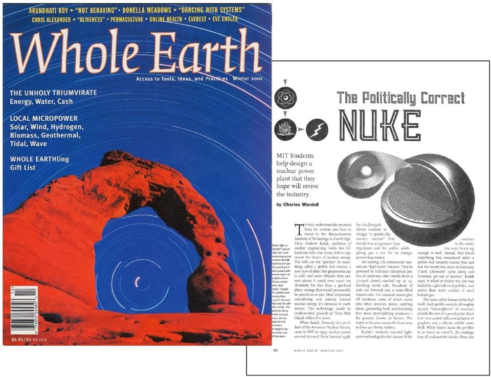
The Politically Correct Nuclear Energy Plant
 The Politically Correct Nuclear Energy Plant Andrew C. Kadak Massachusetts Institute of Technology Ford Distinguished Lecture Series October 31, 2001 Politically Incorrect! High Cost Meltdowns Reprocessing
Research and Development Program of HTGR Fuel in Japan
 Research and Development Program of HTGR Fuel in Japan Kazuhiro SAWA, Shouhei UETA, Tatsuo IYOKU Masuro OGAWA, Yoshihiro KOMORI Department of Advanced Nuclear Heat Technology Department of HTTR Project
Sensitivity Studies of Modular High-Temperature Gas-Cooled Reactor (MHTGR) Postulated Accidents
 Postulated Accidents") Sensitivity Studies of Modular High-Temperature Gas-Cooled Reactor (MHTGR) Postulated Accidents Syd Ball Oak Ridge National Laboratory* P.O. Box 2008 Oak Ridge, TN 37831-6010 USA Tel: (865) 574-0415 Fax:
Sensitivity Studies of Modular High-Temperature Gas-Cooled Reactor (MHTGR) Postulated Accidents Syd Ball Oak Ridge National Laboratory* P.O. Box 2008 Oak Ridge, TN 37831-6010 USA Tel: (865) 574-0415 Fax:
Generation IV Fast Reactors. Dr Richard Stainsby AMEC Richard.Stainsby@amec.com
 Generation IV Fast Reactors Dr Richard Stainsby AMEC Richard.Stainsby@amec.com Contents The Generation IV international research programme on advanced reactors The case for fast reactors The technology:
V K Raina. Reactor Group, BARC
 Critical facility for AHWR and PHWRs V K Raina Reactor Group, BARC India has large reserves of Thorium Critical facility Utilisation of Thorium for power production is a thrust area of the Indian Nuclear
10 Nuclear Power Reactors Figure 10.1
 10 Nuclear Power Reactors Figure 10.1 89 10.1 What is a Nuclear Power Station? The purpose of a power station is to generate electricity safely reliably and economically. Figure 10.1 is the schematic of
BWR Description Jacopo Buongiorno Associate Professor of Nuclear Science and Engineering
 BWR Description Jacopo Buongiorno Associate Professor of Nuclear Science and Engineering 22.06: Engineering of Nuclear Systems 1 Boiling Water Reactor (BWR) Public domain image by US NRC. 2 The BWR is
Physics and Engineering of the EPR
 Physics and Engineering of the EPR Keith Ardron UK Licensing Manager, UK Presentation to IOP Nuclear Industry Group Birchwood Park, Warrington UK, November 10 2010 EPRs in UK EPR is Generation 3+ PWR design
The Very High Temperature Reactor: A Technical Summary
 June 2004 The Very High Temperature Reactor: A Technical Summary Prepared for MPR Associates, Inc. 320 King Street Alexandria, VA 22314 The Very High Temperature Reactor: A Technical Summary June 2004
Torino Nord. Cogeneration Plant. The gas turbine. The steam generator. The Torino Nord cogeneration plant produces electricity and heat for district
 PLANT TORINO NORD Iren Energia is the company in the Iren Group whose core businesses are the production and distribution of electricity, the production and distribution of thermal energy for district
How To Clean Up A Reactor Water Cleanup
 General Electric Systems Technology Manual Chapter 2.8 Reactor Water Cleanup System TABLE OF CONTENTS 2.8 REACTOR CLEANUP SYSTEM... 1 2.8.1 Introduction... 2 2.8.2 System Description... 2 2.8.3 Component
Technical Challenges for Conversion of U.S. High-Performance Research Reactors (USHPRR)
") Technical Challenges for Conversion of U.S. High-Performance Research Reactors (USHPRR) John G. Stevens, Ph.D. Argonne National Laboratory Technical Lead of Reactor Conversion GTRI USHPRR Conversion Program
Technical Challenges for Conversion of U.S. High-Performance Research Reactors (USHPRR) John G. Stevens, Ph.D. Argonne National Laboratory Technical Lead of Reactor Conversion GTRI USHPRR Conversion Program
Dynamic Behavior of BWR
 Massachusetts Institute of Technology Department of Nuclear Science and Engineering 22.06 Engineering of Nuclear Systems Dynamic Behavior of BWR 1 The control system of the BWR controls the reactor pressure,
Assessment of the Next Generation Nuclear Plant Intermediate Heat Exchanger Design
 ANL/EXT-08/32 Assessment of the Next Generation Nuclear Plant Intermediate Heat Exchanger Design Nuclear Engineering Division About Argonne National Laboratory Argonne is a U.S. Department of Energy laboratory
Introduction to Nuclear Fuel Cycle and Advanced Nuclear Fuels
 Introduction to Nuclear Fuel Cycle and Advanced Nuclear Fuels Jon Carmack Deputy National Technical Director Fuel Cycle Technology Advanced Fuels Program February 27, 2011 The Evolution of Nuclear Power
NUCLEAR POWER PLANT SYSTEMS and OPERATION
 Revision 4 July 2005 NUCLEAR POWER PLANT SYSTEMS and OPERATION Reference Text Professor and Dean School of Energy Systems and Nuclear Science University of Ontario Institute of Technology Oshawa, Ontario
SGT5-8000H SCC5-8000H 1S. Experience of Commercial Operation at Irsching 4. ANIMP-ATI, Sesto San Giovanni 26 June 2012
 SGT5-8000H SCC5-8000H 1S Experience of Commercial Operation at Irsching 4 ANIMP-ATI, Sesto San Giovanni 26 June 2012 Massimo Gianfreda 8000H Overview Validation Status Summary Fig. 2 Siemens Large Scale
Pu BURNING, ENERGY GENERATION. STORAGE OF FRESH FUEL FIG. 1. Disposition ofwgpu.
 GT-MHR SPENT FUEL STORAGE DISPOSAL WITHOUT PROCESSING A.I. KIRYUSHIN, N.G. KUZAVKOV, Yu.L. GUSHIN, Yu.P. SUKHAREV OKBM, Nizhny Novgorod, Russian Fderation A.G. Chudin Minatom, Moscow, Russian Federation
VAD. Variable Area Desuperheaters
 Desuperheater overview Steam used in process plants can be superheated, that is, heated to a temperature above saturation. The excess of temperature above its saturation is called 'superheat'. Desuperheated
Boiling Water Reactor Systems
 Boiling Water (BWR) s This chapter will discuss the purposes of some of the major systems and components associated with a boiling water reactor (BWR) in the generation of electrical power. USNRC Technical
COUPLED CFD SYSTEM-CODE SIMULATION OF A GAS COOLED REACTOR
 International Conference on Mathematics and Computational Methods Applied to Nuclear Science and Engineering (M&C 2011) Rio de Janeiro, RJ, Brazil, May 8-12, 2011, on CD-ROM, Latin American Section (LAS)
ASPE Seminar Water Heater Piping Strategies. Presented by Joe Kalarickal, EIT Regional Sales Manager AERCO International
 ASPE Seminar Water Heater Piping Strategies Presented by Joe Kalarickal, EIT Regional Sales Manager AERCO International Presentation Overview Water Heater Piping Strategies How to size a water heater?
Fire Protection Program Of Chashma Nuclear Power Generating Station Pakistan Atomic Energy Commission 5/28/2015 1
 Fire Protection Program Of Chashma Nuclear Power Generating Station Pakistan Atomic Energy Commission 5/28/2015 1 Nuclear Power in Pakistan Nuclear Power Plants Capacity (MWe) Year of Commissioning In
WWER Type Fuel Manufacture in China
 WWER Type Fuel Manufacture in China Yang Xiaodong P.O. Box 273, CJNF, YiBin City, Sichuan, China, [Fax: (+86)8318279161] Abstract: At CJNF, a plan was established for implementation of technical introduction
ANCILLARY SERVICES SUPPLIED TO THE GRID: THE CASE OF THISVI CCGT POWER PLANT (GREECE)
") Claudio Cavandoli, Alessandro Crippa EDISON S.p.A., Engineering Department ANCILLARY SERVICES SUPPLIED TO THE GRID: THE CASE OF THISVI CCGT POWER PLANT (GREECE) 1 ANCILLARY SERVICES SUPPLIED TO THE GRID:
Claudio Cavandoli, Alessandro Crippa EDISON S.p.A., Engineering Department ANCILLARY SERVICES SUPPLIED TO THE GRID: THE CASE OF THISVI CCGT POWER PLANT (GREECE) 1 ANCILLARY SERVICES SUPPLIED TO THE GRID:
Fuel Cycle R&D to Safeguard Advanced Ceramic Fuel Skills Strategic Options
 Fuel Cycle R&D to Safeguard Advanced Ceramic Fuel Skills Strategic Options Fuel Cycle R&D to Safeguard Advanced Ceramic Fuel Skills The Nuclear Renaissance and Fuel Cycle Research and Development Nuclear
SCDAP/RELAP5-3D : A State-of-the-Art Tool for Severe Accident Analyses
 SCDAP/RELAP5-3D : A State-of-the-Art Tool for Severe Accident Analyses D. L. Knudson and J. L. Rempe 2002 RELAP5 International Users Seminar Park City, Utah, USA September 4-6, 2002 Objective and Outline
5.2. Vaporizers - Types and Usage
 5.2. Vaporizers - Types and Usage 5.2.1. General Vaporizers are constructed in numerous designs and operated in many modes. Depending upon the service application the design, construction, inspection,
Preliminary validation of the APROS 3-D core model of the new Loviisa NPP training simulator
 Preliminary validation of the APROS 3-D core model of the new Loviisa NPP training simulator Anssu Ranta-aho, Elina Syrjälahti, Eija Karita Puska VTT Technical Research Centre of Finland P.O.B 1000, FI-02044
www.klmtechgroup.com TABLE OF CONTENT
 Page : 1 of 24 Project Engineering Standard www.klmtechgroup.com KLM Technology #03-12 Block Aronia, Jalan Sri Perkasa 2 Taman Tampoi Utama 81200 Johor Bahru Malaysia S TABLE OF CONTENT SCOPE 2 DEFINITIONS
Flow distribution and turbulent heat transfer in a hexagonal rod bundle experiment
 Flow distribution and turbulent heat transfer in a hexagonal rod bundle experiment K. Litfin, A. Batta, A. G. Class,T. Wetzel, R. Stieglitz Karlsruhe Institute of Technology Institute for Nuclear and Energy
Retrieval of Damaged Components form Experimental Fast Reactor Joyo Reactor Vessel
 Retrieval of Damaged Components form Experimental Fast Reactor Joyo Reactor Vessel June. 8 th, 2010 Yukimoto MAEDA Japan Atomic Energy Agency (JAEA) Experimental fast reactor Joyo Joyo (Oarai R&D Center)
The Physics of Energy sources Nuclear Reactor Practicalities
 The Physics of Energy sources Nuclear Reactor Practicalities B. Maffei Bruno.maffei@manchester.ac.uk www.jb.man.ac.uk/~bm Nuclear Reactor 1 Commonalities between reactors All reactors will have the same
Fukushima 2011. Fukushima Daiichi accident. Nuclear fission. Distribution of energy. Fission product distribution. Nuclear fuel
 Fukushima 2011 Safety of Nuclear Power Plants Earthquake and Tsunami Accident initiators and progression Jan Leen Kloosterman Delft University of Technology 1 2 Nuclear fission Distribution of energy radioactive
DOE s Fuel Cycle Technologies Program - An Overview
 DOE s Fuel Cycle Technologies Program - An Overview William Boyle Director, Used Fuel Disposition R & D (NE-53) Office of Nuclear Energy U.S. Department of Energy ECA Las Vegas, Nevada Agenda Program Mission
DESIGN FEATURES OF BREST REACTORS AND EXPERIMENTAL WORK TO ADVANCE THE CONCEPT OF BREST REACTORS
 DESIGN FEATURES OF BREST REACTORS AND EXPERIMENTAL WORK TO ADVANCE THE CONCEPT OF BREST REACTORS A.I. FILIN, V.V. ORLOV, V.N. LEONOV, A.G. SILA-NOVITSKI, V.S. SMIRNOV, V.S. TSIKUNOV STATE SCIENTIFIC CENTER
Sulfur Tail Gas Thermal Oxidizer Systems By Peter Pickard
 Sulfur Tail Gas Thermal Oxidizer Systems By Peter Pickard Introduction SRU s (Sulfur Recovery Units) are critical pieces of equipment in refineries and gas plants. SRUs remove sulfur compounds from certain
THE COMPARISON OF THE PERFORMANCE FOR THE ALLOY FUEL AND THE INTER-METALLIC DISPERSION FUEL BY THE MACSIS-H AND THE DIMAC
 THE COMPARISON OF THE PERFORMANCE FOR THE ALLOY FUEL AND THE INTER-METALLIC DISPERSION FUEL BY THE MACSIS-H AND THE DIMAC Byoung-Oon Lee, Bong-S. Lee and Won-S. Park Korea Atomic Energy Research Institute
Green Thread Product Data
 Green Thread Product Data Applications Dilute Acids Caustics Produced Water Industrial Waste Hot Water Condensate Return Materials and Construction All pipe manufactured by filament winding process using
Electric Process Heaters & Engineered Systems
 50+ Years of Excellence Electric Process Heaters & Engineered Systems Company Info Gaumer Process is a world leader in the design and manufacturing of electric heaters, controls and engineered systems,
Continuous flow direct water heating for potable hot water
 Continuous flow direct water heating for potable hot water An independently produced White Paper for Rinnai UK 2013 www.rinnaiuk.com In the 35 years since direct hot water systems entered the UK commercial
Fission fragments or daughters that have a substantial neutron absorption cross section and are not fissionable are called...
 KNOWLEDGE: K1.01 [2.7/2.8] B558 Fission fragments or daughters that have a substantial neutron absorption cross section and are not fissionable are called... A. fissile materials. B. fission product poisons.
Operational Reactor Safety 22.091/22.903
 Operational Reactor Safety 22.091/22.903 Professor Andrew C. Kadak Professor of the Practice Lecture 19 Three Mile Island Accident Primary system Pilot operated relief valve Secondary System Emergency
VAD Variable Area Desuperheaters
 Local regulations may restrict the use of this product to below the conditions quoted. In the interests of development and improvement of the product, we reserve the right to change the specification without
Structure and Properties of Atoms
 PS-2.1 Compare the subatomic particles (protons, neutrons, electrons) of an atom with regard to mass, location, and charge, and explain how these particles affect the properties of an atom (including identity,
DEMONSTRATION ACCELERATOR DRIVEN COMPLEX FOR EFFECTIVE INCINERATION OF 99 Tc AND 129 I
 DEMONSTRATION ACCELERATOR DRIVEN COMPLEX FOR EFFECTIVE INCINERATION OF 99 Tc AND 129 I A.S. Gerasimov, G.V. Kiselev, L.A. Myrtsymova State Scientific Centre of the Russian Federation Institute of Theoretical
HOW DOES A NUCLEAR POWER PLANT WORK?
 HOW DOES A NUCLEAR POWER PLANT WORK? O n t a r i o P o w e r G e n e r a t i o n P U T T I N G O U R E N E R G Y T O U S G O O D E O N T A R I O P O W E R G E N E R A T I O N What a Nuclear Reactor Does
INTEC Engineering GmbH Heating Solutions for the Marine Industry
 INTEC Engineering GmbH Heating Solutions for the Marine Industry Thermal Oil Heaters Heating Solutions for the Marine Industry Compared to conventional plants using hot water or steam, thermal oil as a
MCQ - ENERGY and CLIMATE
 1 MCQ - ENERGY and CLIMATE 1. The volume of a given mass of water at a temperature of T 1 is V 1. The volume increases to V 2 at temperature T 2. The coefficient of volume expansion of water may be calculated
Olkiluoto 3 Project June 2010
 Olkiluoto 3 Project June 2010 Author: R&S Communications Department, La Défense, France. The reproduction, transmission or use of this document or its contents is not permitted without express written
ADDITIONAL INFORMATION ON MODERN VVER GEN III TECHNOLOGY. Mikhail Maltsev Head of Department JSC Atomenergoproekt
 ADDITIONAL INFORMATION ON MODERN VVER GEN III TECHNOLOGY Mikhail Maltsev Head of Department JSC Atomenergoproekt February 12, 2015 Introduction The main intention of this presentation is to provide: -
C. starting positive displacement pumps with the discharge valve closed.
 KNOWLEDGE: K1.04 [3.4/3.6] P78 The possibility of water hammer in a liquid system is minimized by... A. maintaining temperature above the saturation temperature. B. starting centrifugal pumps with the
1. A belt pulley is 3 ft. in diameter and rotates at 250 rpm. The belt which is 5 ins. wide makes an angle of contact of 190 over the pulley.
 Sample Questions REVISED FIRST CLASS PARTS A1, A2, AND A3 (NOTE: these questions are intended as representations of the style of questions that may appear on examinations. They are not intended as study
Appendix 1.0 Next Generation Nuclear Plant
 Appendix 1.0 Next Generation Nuclear Plant A1-1 This page intentionally left blank. A1-2 CONTENTS ACRONYMS... 7 A1.1 INTRODUCTION AND BACKGROUND... 11 A1.1.1 System Description...11 A1.1.2 Overall System
Process Integration of Chemical Looping Combustion with Oxygen Uncoupling in a Coal-Fired Power Plant
 Process Integration of Chemical Looping Combustion with Oxygen Uncoupling in a Coal-Fired Power Plant Petteri Peltola 1, Maurizio Spinelli 2, Aldo Bischi 2, Michele Villani 2, Matteo C. Romano 2, Jouni
PERFORMANCE EVALUATION OF NGCC AND COAL-FIRED STEAM POWER PLANTS WITH INTEGRATED CCS AND ORC SYSTEMS
 ASME ORC 2015 3rd International Seminar on ORC Power Systems 12-14 October 2015, Brussels, Belgium PERFORMANCE EVALUATION OF NGCC AND COAL-FIRED STEAM POWER PLANTS WITH INTEGRATED CCS AND ORC SYSTEMS Vittorio
Lead-Cooled Fast Reactor BREST Project Status and Prospects
 資 料 4-3 第 11 回 GIF-LFR pssc (イタリア ピサ 2012 年 4 月 16 日 ) ロシア 側 発 表 資 料 V. S. Smirnov State Atomic Energy Corporation ROSATOM Open Joint-Stock Company N.A. Dollezhal Research and Development Institute of
VALIDATION, MODELING, AND SCALE-UP OF CHEMICAL LOOPING COMBUSTION WITH OXYGEN UNCOUPLING
 VALIDATION, MODELING, AND SCALE-UP OF CHEMICAL LOOPING COMBUSTION WITH OXYGEN UNCOUPLING A research program funded by the University of Wyoming School of Energy Resources Executive Summary Principal Investigator:
Chapter 1 The Development of Nuclear Energy in the World
 Chapter 1 The Development of Nuclear Energy in the World Abstract In 2011 there were about 436 commercial nuclear power reactors operating in the world with a total capacity of 370 GW(e). Nuclear energy
February 19, 2014. Senior Fellow, Nuclear Energy Systems & Services Division Power Systems Company
 JAPAN-U.S. DECOMISSIONING AND REMEDIATION FUKUSHIMA RECOVERY FORUM February 19, 2014 Senior Fellow, Nuclear Energy Systems & Services Division Power Systems Company Toshiba global formation Information
Building New Generation Nuclear Plants Worldwide : AREVA's Experience
 Building New Generation Nuclear Plants Worldwide : AREVA's Experience Philippe Guay Senior Vice President, New Builds Offers AREVA 37 th WNA Symposium 12-14 September 2012 LONDON Projects status The value
The EPR reactor the reference for New Build
 The EPR reactor the reference for New Build The reference for New Build The Reference for Safety The EPR design offers the highest level of safety: Already licensed in France, Finland and China Strong
A MTR FUEL ELEMENT FLOW DISTRIBUTION MEASUREMENT PRELIMINARY RESULTS
 A MTR FUEL ELEMENT FLOW DISTRIBUTION MEASUREMENT PRELIMINARY RESULTS W. M. Torres, P. E. Umbehaun, D. A. Andrade and J. A. B. Souza Centro de Engenharia Nuclear Instituto de Pesquisas Energéticas e Nucleares
Adapting Gas-Power Generation to New Role in Low-Carbon Energy Systems
 Adapting Gas-Power Generation to New Role in Low-Carbon Energy Systems Sandra Scalari Enel Ingegneria e Ricerca SpA Copenhagen, May 27-28 th 2014 Enel Presentation Generation Shift & Market in Europe Enel
Gas Chromatography Liner Selection Guide
 Gas Chromatography Liner Selection Guide Peter Morgan, Thermo Fisher Scientific, Runcorn, Cheshire, UK Technical Note 20551 Key Words Liner, focus Abstract The liner serves an important function in allowing
PROPOSALS FOR UNIVERSITY REACTORS OF A NEW GENERATION
 PROPOSALS FOR UNIVERSITY REACTORS OF A NEW GENERATION Introduction R.P. Kuatbekov, O.A. Kravtsova, K.A. Nikel, N.V. Romanova, S.A. Sokolov, I.T. Tretiyakov, V.I. Trushkin (NIKIET, Moscow, Russia) Worldwide,
Hot Water Boilers and Controls Why Condensing Boilers are Different. Presented Oct. 14, 2008 Long Island Chapter, ASHRAE
 Hot Water Boilers and Controls Why Condensing Boilers are Different Presented Oct. 14, 2008 Long Island Chapter, ASHRAE H.W. Boilers and Controls Major types of boilers Advantages and disadvantages Resistance
Investigations of a Long-Distance 1000 MW Heat Transport System with APROS Simulation Software
 th International Conference on Structural Mechanics in Reactor Technology (SMiRT ) Espoo, Finland, August 9-4, 9 SMiRT -Division 3, Paper 56 Investigations of a Long-Distance MW Heat Transport System with
Coil-Wound Heat Exchangers
 Coil-Wound Heat Exchangers 2 Contents. 3 Introduction 4 Characteristics Thermal and hydraulic design 5 Mechanical design Fabrication and special features Applications 6 Benefits Selected references 7 Coil-wound
The Piping System Model a New Life Cycle Document. Elements of the Piping System Model
 Piping System Model as a Life Cycle Document White Paper Introduction When designing piping systems, a variety of documents are created providing the details necessary to design, purchase, build, and test
ECOplus Solar Cylinder
 TECHNICAL INFORMATION Solar Cylinder Wagner& Co Connection Options for CONVECTROL II The Effective Convection Brake Technically and fluidically optimized barriers separate the water cooled in the pipes
Nozzle Loads, Piping Stresses, and the Effect of Piping on Equipment
 Nozzle Loads, Piping Stresses, and the Effect of Piping on Equipment By Patty Brown & Mark van Ginhoven November 13, 2009 1 CA 2009 Fluor Corporation. All Rights Reserved. Topics Covered Introduction Nozzle
HIGH STANDARD VALVES FOR NON-STANDARD CONDITIONS.
 HIGH STANDARD VALVES FOR NON-STANDARD CONDITIONS. ZWICK: MANUFACTURER OF HIGH STANDARD TRIPLE OFFSET VALVES. 100% ZERO-LEAKAGE 100% MADE IN GERMANY 100% QUALITY Zwick is a leading manufacturer of valves
Typical Cooling Load Profile
 Ice Storage Systems and Impact on Electric Demand Georges Hoeterickx Specialists in Heat Transfer Products and Services 1 2 Cooling Load Typical Cooling Load Profile 0 2 4 6 8 10 12 14 16 18 20 22 Time
Select Radiators Installation Guide
 Select Radiators Installation Guide Table of Contents Informational Symbols...3 Before You Begin...4 Select Rough-In... 5 Connection Installation...6 Optional Piping Arrangements...7 Conventional Wall
NUCLEAR ENERGY RESEARCH INITIATIVE
 NUCLEAR ENERGY RESEARCH INITIATIVE Experimental and CFD Analysis of Advanced Convective Cooling Systems PI: Victor M. Ugaz and Yassin A. Hassan, Texas Engineering Experiment Station Collaborators: None
Nuclear power plant systems, structures and components and their safety classification. 1 General 3. 2 Safety classes 3. 3 Classification criteria 3
 GUIDE 26 June 2000 YVL 2.1 Nuclear power plant systems, structures and components and their safety classification 1 General 3 2 Safety classes 3 3 Classification criteria 3 4 Assigning systems to safety
A short history of reactors
 A short history of reactors Janne Wallenius Reactor Physics, KTH Objectives of this meeting The origin of nuclear power was considerably more diversified than the existing variation in commercial reactor
Progress on High Efficiency Coal Power Plants
 CoalFleet for Tomorrow Progress on High Efficiency Coal Power Plants Dr. Jeff Phillips Sr. Program Manager, Generation McIlvaine Webcast March 1, 2012 CoalFleet for Tomorrow is a registered service mark
OUTCOME 2 INTERNAL COMBUSTION ENGINE PERFORMANCE. TUTORIAL No. 5 PERFORMANCE CHARACTERISTICS
 UNIT 61: ENGINEERING THERMODYNAMICS Unit code: D/601/1410 QCF level: 5 Credit value: 15 OUTCOME 2 INTERNAL COMBUSTION ENGINE PERFORMANCE TUTORIAL No. 5 PERFORMANCE CHARACTERISTICS 2 Be able to evaluate
HEAVY DUTY STORAGE GAS
 Multi-Fin flue technology Flue damper saves energy Electronic controls HEAVY DUTY STORAGE GAS Dependability The Rheem heavy duty gas range is the work horse of the industry having proved itself over many
Low grade thermal energy sources and uses from the process industry in the UK
 Low grade thermal energy sources and uses from the process industry in the UK Yasmine Ammar, Sharon Joyce, Rose Norman, Yaodong Wang, Anthony P. Roskilly Sustainable Thermal Energy Management in the Process
Diffusion and Fluid Flow
 Diffusion and Fluid Flow What determines the diffusion coefficient? What determines fluid flow? 1. Diffusion: Diffusion refers to the transport of substance against a concentration gradient. ΔS>0 Mass
NUCLEARINSTALLATIONSAFETYTRAININGSUPPORTGROUP DISCLAIMER
 NUCLEARINSTALLATIONSAFETYTRAININGSUPPORTGROUP DISCLAIMER Theinformationcontainedinthisdocumentcannotbechangedormodifiedinanywayand shouldserveonlythepurposeofpromotingexchangeofexperience,knowledgedissemination
Public SUMMARY OF EU STRESS TEST FOR LOVIISA NUCLEAR POWER PLANT
 1 (8) SUMMARY OF EU STRESS TEST FOR LOVIISA NUCLEAR POWER PLANT 1 LOVIISA NUCLEAR POWER PLANT Loviisa town is located approximately 90 km eastwards from Helsinki at the coast of Gulf of Finland. Loviisa
Generating Current Electricity: Complete the following summary table for each way that electrical energy is generated. Pros:
 P a g e 1 Generating Current Electricity: Complete the following summary table for each way that electrical energy is generated. Generating Electrical Energy Using Moving Water: Hydro-Electric Generation
Air Eliminators and Combination Air Eliminators Strainers
 Description Air Eliminators and Combination Air Eliminator Strainers are designed to provide separation, elimination and prevention of air in piping systems for a variety of installations and conditions.
Condensing Boiler Efficiency
 Condensing Boiler Efficiency Date: July 17, 2012 PRES E NT ED BY DO N L E O NA RDI LE O N A RD I I NC. HV AC T RAI N I N G & C ON SU LT IN G Concepts 1 The current state of evolution in boiler design 2
TANKLESS WATER HEATER INSTALLATION DIAGRAMS
 TANKLESS WATER HEATER INSTALLATION DIAGRAMS Installation Diagrams Tankless Installation / Optional Return Small 10-15 Gallon Point-of-Use Water Single and Optional Return : One single, small capacity water
Control Device Requirements Charts For Oil and Gas Handling and Production Facilities
 Device Charts For Oil and Gas Handling and Production Facilities Purpose/Scope: The purpose of this document is to provide standardized guidance for use by the regulated community and air permit reviewers,
Operating Performance: Accident Management: Severe Accident Management Programs for Nuclear Reactors REGDOC-2.3.2
 Operating Performance: Accident Management: Severe Accident Management Programs for Nuclear Reactors REGDOC-2.3.2 September 2013 Accident Management: Severe Accident Regulatory Document REGDOC-2.3.2 Canadian
TECHNICAL MEETING ON IN-PILE TESTING AND INSTRUMENTATION FOR DEVELOPMENT OF GENERATION-IV FUELS AND STRUCTURAL MATERIALS
 651-T1-TM-42785 TECHNICAL MEETING ON IN-PILE TESTING AND INSTRUMENTATION FOR DEVELOPMENT OF GENERATION-IV FUELS AND STRUCTURAL MATERIALS I. BACKGROUND Halden, Norway 21 24 August 2012 INFORMATION SHEET
Advances in Thermal Dispersion Mass Flow Meter Accuracy
 Advances in Thermal Dispersion Mass Flow Meter Accuracy By Dan McQueen President Fluid Components International (FCI) Advances in Thermal Dispersion Mass Flow Meter Accuracy By Dan McQueen President Fluid
No. Name Description Main input Data Main Output Data. cooling duty, process in/out temperature, inlet air temperature
 1 AIRCOOLER Air cooler preliminary sizing cooling duty, process in/out temperature, inlet air temperature No of fans, Air cooler Dimension, bare area, no of rows, Fan Diameter, fan power 2 BLOW DOWN FACILITATOR
Development Study of Nuclear Power Plants for the 21st Century
 Development Study of Nuclear Power Plants for the 21st Century Hitachi Review Vol. 50 (2001), No. 3 61 Kumiaki Moriya Masaya Ohtsuka Motoo Aoyama, D.Eng. Masayoshi Matsuura OVERVIEW: Making use of nuclear
Mechanical Seal Piping Plans
 Mechanical Seal Piping Plans Single Seals plans 01, 02, 03, 11, 13, 14, 21, 23, 31, 32, 41 Dual Seals plans 52, 53A, 53B, 53C, 54, 55 Quench Seals plans 62, 65A, 65B, 66A, 66B Gas Seals plans 72, 74, 75,
CFD Topics at the US Nuclear Regulatory Commission. Christopher Boyd, Ghani Zigh Office of Nuclear Regulatory Research June 2008
 CFD Topics at the US Nuclear Regulatory Commission Christopher Boyd, Ghani Zigh Office of Nuclear Regulatory Research June 2008 Overview Computational Fluid Dynamics (CFD) is playing an ever increasing
7.1 General 5 7.2 Events resulting in pressure increase 5
 GUIDE YVL 2.4 / 24 Ma r ch 2006 Primary and secondary circuit pressure control at a nuclear power plant 1 Ge n e r a l 3 2 General design requirements 3 3 Pressure regulation 4 4 Overpressure protection