|
|
|
- Aldous Barnaby O’Brien’
- 7 years ago
- Views:
Transcription
1
2
3
4
5

6

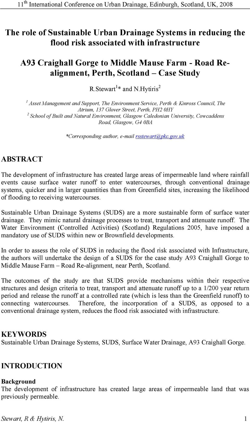
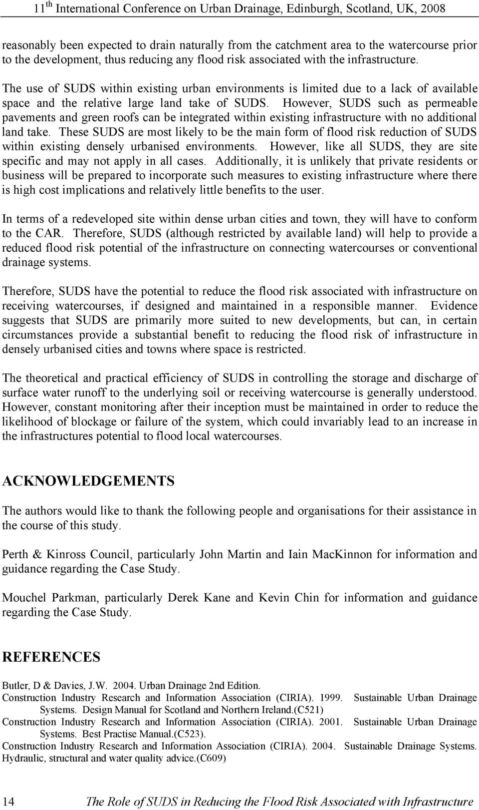
7 SWALE AT 1.0 SOUTH Stage 1 - Calculate Treatment Volume (1/1 Year Return Period) V T= Treatment Volume = A P * I / 1000 Where: A P = Catchment Area (m 2 ) = 800 V T= Treatment Volume = m 3 /hr I = Average annual rainfall for 1/1 year strom (mm/hr) = 27 Stage 2 - Calculate Velocity (V) / Treatment Flow (Q F ) / Residence Time (R T ) (1/1 Year Return Period) Swale Dimensions MANNING'S EQUATION V = 1 Base (b) 0.75 n R2/3 1/2 S o Water Height (h A) 0.1 Side length actual (L A) 0.9 Side length - Wet (L W) 0.30 Where: answer dimension Swale height (h) 0.3 Mannings Angle Length (A L) 0.32 Roughness (n) 0.30 m -1/3 s Hydraulic Radius (R) 0.08 m Where: Cross sectional area of swale n = from CIRIA, 2004 guidance where water is running (A) m 2 R = A/P W Wetted Perimeter of A = (b*h A)+(2*h A*h/2) Swale (P w) 1.38 m P W = A L+A L+b Swale Slope (S o) SO = 1 in 99 (0.0101) Velocity (V) 0.06 m/s Volume of Flow = Q F = V * A * 60 * 60 QF m 3 /hr Where: Residence Time = (R T) = SL / V / 60 Swale Length (SL) (m) = 73 RT mins Stage 3 - Checks - (1/1 Year Return Period) Type Purpose Pass? Velocity V < 0.3m/s yes Volume V T < Q F yes Residence Time R T > 10mins yes Comments
 0.32 Roughness (n) 0.30 m -1/3 s Hydraulic Radius (R) 0.08 m Where: Cross sectional area of swale n = from CIRIA, 2004 guidance where water is running (A) 0.")
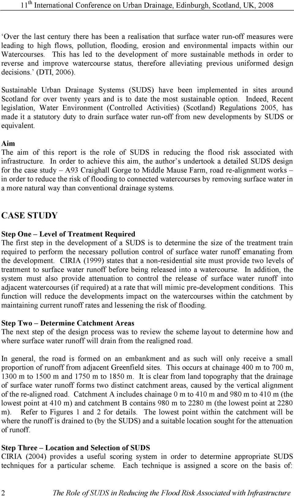
8 SWALE AT 1.0 SOUTH Stage 4 - Calculate Volume (1/30 Year Return Period) QF(1/30)= Flow of 1/30 return period = AP * I / 1000 Where: A P = Catchment Area (m 2 ) = 800 Q F(1/30)= Flow of 1/30 return period = m 3 /hr I = Average annual rainfall for 1/30 year strom (mm/hr) = 65 Stage 5 - Calculate Velocity (V) / Swale Flow Capacity (Q SFC(1/30) ) for 1/30 Year Return Period Swale Dimensions MANNING'S EQUATION V = 1 Base (b) 0.75 n R2/3 1/2 S o Water Height (ha) 0.3 Side length actual (L A) 0.9 Side length - Wet (LW) 0.90 Where: answer dimension Swale height (h) 0.3 Mannings Angle Length (AL) 0.95 Roughness (n) 0.30 m -1/3 s Hydraulic Radius (R) 0.12 m Where: Cross sectional area of swale n = from CIRIA, 2004 guidance where water is running (A) m 2 R = A/P W Wetted Perimeter of A = (b*h A)+(2*h A*h/2) Swale (P w) 2.65 m P W = A L+A L+b Swale Slope (S o) S O = 1 in 99 (0.0101) Velocity (V) 0.08 m/s Swale Flow Capacity = Q SFC(1/30) = V * A * 60 * 60 Q SFC(1/30) m 3 /hr Stage 6 - Checks - (1/30 Year Return Period) Type Purpose Pass? Velocity V < 1.0m/s yes Volume QF(1/30) < Q SFC(1/30) yes Comments
 0.75 n R2/3 1/2 S o Water Height (ha) 0.3 Side length actual (L A) 0.9 Side length - Wet (LW) 0.90 Where: answer dimension Swale height (h) 0.3 Mannings Angle Length (AL) 0.")
9 Branch L (m) Grad (1 in?) D (mm) V (m/s) T f (min) T c (min) I (mm/hr) A P (hec) εa P (hec) Q (m 3 /s) All Q (m 3 /s) Remarks Pass Pass Pass Pass Pass Fail Pass

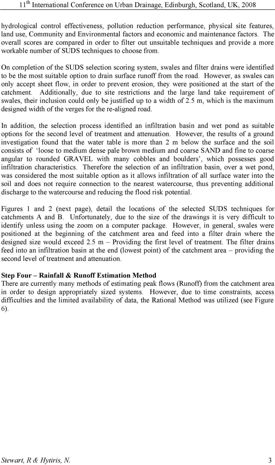
10 PIPE DESIGN - USING RATIONAL METHOD Rational Method =Q = Flow in pipe (m 3 /s) = C * A P * I Where: C = (If AP is in hectares) T = duration of storm = T c AP = Impermeable Area (Hectares) Tc = Time of Concentration (minutes) = T f (of all connecting pipes) + 4mins(T e - time of entry 30 * 25.4 I = Rainfall intensity (mm/hr) = Where: into pipe system) T + 10 Tf = Time of Flow (minutes) = L / V / 60 Additional information L = Length (m) Grad = Gradient (1 in? Slope)= Determined as per CIRIA, 2005 Guidance D = Diameter of pipe (mm) V = Velocity (m/s) = interpolated from hydraulic charts εap = summation of impermeable areas for all connecting pipes (Hectares) All Q = Allowable Flow capacity of pipe = interpolated from hydraulic charts Catchment A Outfall Branch L Grad D V Tf Tc I Ap εap Q All Q Remarks Pass Catchment B Outfall Pass
= Determined as per CIRIA, 2005 Guidance D = Diameter of pipe (mm) V = Velocity (m/s) = interpolated from hydraulic charts εap = summation of impermeable areas for all connecting pipes")
11

12

13

14
15

From Civil 3D, with Love
 From Civil 3D, with Love Download the zip file containing the files needed for the exercise. Extract the files to a convenient location on your hard drive before you begin. The files associated with this
Storm Drainage Systems 11.9-1
 Storm Drainage Systems 11.9-1 11.9 Gutter Flow Calculations 11.9.1 Introduction Gutter flow calculations are necessary in order to relate the quantity of flow (Q) in the curbed channel to the spread of
CHAPTER 3 STORM DRAINAGE SYSTEMS
 CHAPTER 3 STORM DRAINAGE SYSTEMS 3.7 Storm Drains 3.7.1 Introduction After the tentative locations of inlets, drain pipes, and outfalls with tail-waters have been determined and the inlets sized, the next
Rational Method Hydrologic Calculations with Excel. Rational Method Hydrologic Calculations with Excel, Course #508. Presented by:
 Rational Method Hydrologic Calculations with Excel, Course #508 Presented by: PDH Enterprises, LLC PO Box 942 Morrisville, NC 27560 www.pdhsite.com Calculation of peak storm water runoff rate from a drainage
What is the most obvious difference between pipe flow and open channel flow????????????? (in terms of flow conditions and energy situation)
") OPEN CHANNEL FLOW 1 3 Question What is the most obvious difference between pipe flow and open channel flow????????????? (in terms of flow conditions and energy situation) Typical open channel shapes Figure
OPEN CHANNEL FLOW 1 3 Question What is the most obvious difference between pipe flow and open channel flow????????????? (in terms of flow conditions and energy situation) Typical open channel shapes Figure
Module 7: Hydraulic Design of Sewers and Storm Water Drains. Lecture 7 : Hydraulic Design of Sewers and Storm Water Drains
 1 P age Module 7: Hydraulic Design of Sewers and Storm Water Drains Lecture 7 : Hydraulic Design of Sewers and Storm Water Drains 2 P age 7.1 General Consideration Generally, sewers are laid at steeper
LECTURE 1: Review of pipe flow: Darcy-Weisbach, Manning, Hazen-Williams equations, Moody diagram
 LECTURE 1: Review of pipe flow: Darcy-Weisbach, Manning, Hazen-Williams equations, Moody diagram 1.1. Important Definitions Pressure Pipe Flow: Refers to full water flow in closed conduits of circular
M6a: Open Channel Flow (Manning s Equation, Partially Flowing Pipes, and Specific Energy)
") M6a: Open Channel Flow (, Partially Flowing Pipes, and Specific Energy) Steady Non-Uniform Flow in an Open Channel Robert Pitt University of Alabama and Shirley Clark Penn State - Harrisburg Continuity
M6a: Open Channel Flow (, Partially Flowing Pipes, and Specific Energy) Steady Non-Uniform Flow in an Open Channel Robert Pitt University of Alabama and Shirley Clark Penn State - Harrisburg Continuity
Basic Hydrology. Time of Concentration Methodology
 Basic Hydrology Time of Concentration Methodology By: Paul Schiariti, P.E., CPESC Mercer County Soil Conservation District What is the Time of Concentration? The time it takes for runoff to travel from
CHAPTER 4 STORM DRAINAGE SYSTEMS
 CHAPTER 4 STORM DRAINAGE SYSTEMS 4.1 Overview... 4-1 4.1.1 Introduction... 4-1 4.1.2 Inlet Definition... 4-1 4.1.3 Criteria... 4-1 4.2 Pavement Drainage... 4-2 4.2.1 Introduction... 4-2 4.2.2 Storm Drain
Travel Time. Computation of travel time and time of concentration. Factors affecting time of concentration. Surface roughness
 3 Chapter 3 of Concentration and Travel Time Time of Concentration and Travel Time Travel time ( T t ) is the time it takes water to travel from one location to another in a watershed. T t is a component
6-1 Introduction. 1. Storm drain that does not require pressure testing. 2. Lateral that does not require pressure testing.
 Chapter 6 Storm Drains 6-1 Introduction A storm drain (storm sewer) is a network of pipes that conveys surface drainage from a surface inlet or through a manhole, to an outfall. Storm drains are defined
Spreadsheet Use for Partially Full Pipe Flow Calculations
 Spreadsheet Use for Partially Full Pipe Flow Calculations Course No: C02-037 Credit: 2 PDH Harlan H. Bengtson, PhD, P.E. Continuing Education and Development, Inc. 9 Greyridge Farm Court Stony Point, NY
LECTURE 9: Open channel flow: Uniform flow, best hydraulic sections, energy principles, Froude number
 LECTURE 9: Open channel flow: Uniform flow, best hydraulic sections, energy principles, Froude number Open channel flow must have a free surface. Normally free water surface is subjected to atmospheric
PART 6 HA 113/05 DRAINAGE
 DESIGN MANUAL FOR ROADS AND BRIDGES VOLUME 4 SECTION 2 GEOTECHNICS AND DRAINAGE DRAINAGE PART 6 HA 113/5 COMBINED CHANNEL AND PIPE SYSTEM FOR SURFACE WATER DRAINAGE SUMMARY This Advice Note gives guidance
APPENDIX B DESIGN GUIDELINES FOR APPROVED TREATMENT METHODS
 APPENDIX B DESIGN GUIDELINES FOR APPROVED TREATMENT METHODS PLANTER BOXES 1. Determine the impervious area contributing flow to the planter box (see Chapter 4.2). 2. Assumption: Typical soil infiltration
Lecture 24 Flumes & Channel Transitions. I. General Characteristics of Flumes. Flumes are often used:
 Lecture 24 Flumes & Channel Transitions I. General Characteristics of Flumes Flumes are often used: 1. Along contours of steep slopes where minimal excavation is desired 2. On flat terrain where it is
Stormwater Management Functional Servicing Report
 Stormwater Management Functional Servicing Report Part of Lot 12, Concession 10 Township of Cavan Monaghan Ian Cameron Rural Subdivision Engage Project No. 14016 Engage Engineering Ltd. January 7, 2015
DRAINAGE PART 3 HA 102/00 SPACING OF ROAD GULLIES SUMMARY
 DESIGN MANUAL FOR ROADS AND BRIDGES VOLUME 4 SECTION 2 GEOTECHNICS AND DRAINAGE DRAINAGE PART 3 HA 102/00 SPACING OF ROAD GULLIES SUMMARY This Advice Note provides design guidance for determining the length
The value of the wastewater flow used for sewer design is the daily peak flow. This can be estimated as follows:
 This Section presents the theory of simplified sewer design. Firstly, in Section 2.1, the peak daily wastewater flow in the length of sewer being designed is described. Section 2.2 presents the trigonometric
Land Disturbance, Erosion Control and Stormwater Management Checklist. Walworth County Land Conservation Department
 Land Disturbance, Erosion Control and Stormwater Management Checklist Walworth County Land Conservation Department The following checklist is designed to assist the applicant in complying with the Walworth
Chapter 9. Steady Flow in Open channels
 Chapter 9 Steady Flow in Open channels Objectives Be able to define uniform open channel flow Solve uniform open channel flow using the Manning Equation 9.1 Uniform Flow in Open Channel Open-channel flows
Open channel flow Basic principle
 Open channel flow Basic principle INTRODUCTION Flow in rivers, irrigation canals, drainage ditches and aqueducts are some examples for open channel flow. These flows occur with a free surface and the pressure
REHABILITATION METHOD FOR INCREASING FLOW VELOCITY AND REDUCING SEDIMENTATION
 .asu/ North American Society for Trenchless Technology (NASTT) NO-DIG 2005 Orlando, Florida April 24-27, 2005 REHABILITATION METHOD FOR INCREASING FLOW VELOCITY AND REDUCING SEDIMENTATION Hwan-Kook Hwang
L r = L m /L p. L r = L p /L m
 NOTE: In the set of lectures 19/20 I defined the length ratio as L r = L m /L p The textbook by Finnermore & Franzini defines it as L r = L p /L m To avoid confusion let's keep the textbook definition,
SECTION 08000 STORM DRAINAGE TABLE OF CONTENTS
 SECTION 08000 STORM DRAINAGE 08010 DESIGN A. Location B. Sizing TABLE OF CONTENTS 08020 MATERIALS A. Pipe Materials B. Structure Materials C. Installation D. Inlets and Outlets 08030 INSPECTIONS AND TESTING
CHAPTER 5. Storm Sewer
 CHAPTER 5 Storm Sewer A. Introduction All proposed developments shall have a properly designed and constructed storm water conveyance system. This chapter deals only with the conveyance system. Storm water
Pressure drop in pipes...
 Pressure drop in pipes... PRESSURE DROP CALCULATIONS Pressure drop or head loss, occurs in all piping systems because of elevation changes, turbulence caused by abrupt changes in direction, and friction
Catchment Scale Processes and River Restoration. Dr Jenny Mant Jenny@therrc.co.uk. The River Restoration Centre therrc.co.uk
 Catchment Scale Processes and River Restoration Dr Jenny Mant Jenny@therrc.co.uk The River Restoration Centre therrc.co.uk 3 Main Catchment Elements Hydrology Energy associated with the flow of water affects
Circles - Past Edexcel Exam Questions
 ircles - Past Edecel Eam Questions 1. The points A and B have coordinates (5,-1) and (13,11) respectivel. (a) find the coordinates of the mid-point of AB. [2] Given that AB is a diameter of the circle,
Lecture 22 Example Culvert Design Much of the following is based on the USBR technical publication Design of Small Canal Structures (1978)
") Lecture 22 Example Culvert Design Much of the following is based on the USBR technical publication Design of Small Canal Structures (1978) I. An Example Culvert Design Design a concrete culvert using the
Lecture 22 Example Culvert Design Much of the following is based on the USBR technical publication Design of Small Canal Structures (1978) I. An Example Culvert Design Design a concrete culvert using the
Riprap-lined Swale (RS)
") Riprap-lined Swale (RS) Practice Description A riprap-lined swale is a natural or constructed channel with an erosion-resistant rock lining designed to carry concentrated runoff to a stable outlet. This
Riprap-lined Swale (RS) Practice Description A riprap-lined swale is a natural or constructed channel with an erosion-resistant rock lining designed to carry concentrated runoff to a stable outlet. This
Experiment (13): Flow channel
: Flow channel") Introduction: An open channel is a duct in which the liquid flows with a free surface exposed to atmospheric pressure. Along the length of the duct, the pressure at the surface is therefore constant and
Introduction: An open channel is a duct in which the liquid flows with a free surface exposed to atmospheric pressure. Along the length of the duct, the pressure at the surface is therefore constant and
Chapter 8: Flow in Pipes
 Objectives 1. Have a deeper understanding of laminar and turbulent flow in pipes and the analysis of fully developed flow 2. Calculate the major and minor losses associated with pipe flow in piping networks
CODE OF PRACTICE - VOLUME TWO - TRAIN SYSTEM [CP2] TRANSADELAIDE INFRASTRUCTURE SERVICES. Issue: 2 Date: 26/09/08 Page: 1 of 21
![CODE OF PRACTICE - VOLUME TWO - TRAIN SYSTEM [CP2] TRANSADELAIDE INFRASTRUCTURE SERVICES. Issue: 2 Date: 26/09/08 Page: 1 of 21](/thumbs/25/6262615.jpg "CODE OF PRACTICE - VOLUME TWO - TRAIN SYSTEM [CP2] TRANSADELAIDE INFRASTRUCTURE SERVICES. Issue: 2 Date: 26/09/08 Page: 1 of 21") Issue: 2 Date: 26/09/08 Page: 1 of 21 TRACK AND CIVIL INFRASTRUCTURE CODE OF PRACTICE VOLUME TWO - TRAIN SYSTEM [CP2] DRAINAGE 2004 No part of this document may be reproduced without prior written consent
Issue: 2 Date: 26/09/08 Page: 1 of 21 TRACK AND CIVIL INFRASTRUCTURE CODE OF PRACTICE VOLUME TWO - TRAIN SYSTEM [CP2] DRAINAGE 2004 No part of this document may be reproduced without prior written consent
CEE 370 Fall 2015. Laboratory #3 Open Channel Flow
 CEE 70 Fall 015 Laboratory # Open Channel Flow Objective: The objective of this experiment is to measure the flow of fluid through open channels using a V-notch weir and a hydraulic jump. Introduction:
CHAPTER 2 HYDRAULICS OF SEWERS
 CHAPTER 2 HYDRAULICS OF SEWERS SANITARY SEWERS The hydraulic design procedure for sewers requires: 1. Determination of Sewer System Type 2. Determination of Design Flow 3. Selection of Pipe Size 4. Determination
Characteristics of the Four Main Geometrical Figures
 Math 40 9.7 & 9.8: The Big Four Square, Rectangle, Triangle, Circle Pre Algebra We will be focusing our attention on the formulas for the area and perimeter of a square, rectangle, triangle, and a circle.
Lecture 17 Design of Earthen Canals. I. General
 Lecture 17 Design of Earthen Canals I. General Much of this information applies in general to both earthen and lined canals Attempt to balance cuts and fills to avoid waste material and or the need for
Emergency Spillways (Sediment basins)
") Emergency Spillways (Sediment basins) DRAINAGE CONTROL TECHNIQUE Low Gradient Velocity Control Short-Term Steep Gradient Channel Lining Medium-Long Term Outlet Control Soil Treatment Permanent [1] [1]
Emergency Spillways (Sediment basins) DRAINAGE CONTROL TECHNIQUE Low Gradient Velocity Control Short-Term Steep Gradient Channel Lining Medium-Long Term Outlet Control Soil Treatment Permanent [1] [1]
SECTION 6A STORM DRAIN DESIGN Mar. 2002 S E C T I O N 6A STORM DRAIN - DESIGN
 S E C T I O N 6A STORM DRAIN - DESIGN 6A.l Scope 6A.2 Storm Water Quantity 6A.3 Storm Drain Hydraulics 6A.4 Depths 6A.5 Locations 6A.6 Curved Storm Drains 6A.7 Manholes 6A.8 Catch basins 6A.9 Storm Drain
SECTION 5 - STORM DRAINS
 Drainage Criteria Manual SECTION 5 - STORM DRAINS 5.1.0 GENERAL This The purpose of this section discusses briefly is to consider the hydraulic aspects of storm drains and their appurtenances in a storm
Module 6 : Quantity Estimation of Storm Water. Lecture 6 : Quantity Estimation of Storm Water
 1 P age Module 6 : Quantity Estimation of Storm Water Lecture 6 : Quantity Estimation of Storm Water 2 P age 6.1 Factors Affecting the Quantity of Stormwater The surface run-off resulting after precipitation
OPEN-CHANNEL FLOW. Free surface. P atm
 OPEN-CHANNEL FLOW Open-channel flow is a flow of liquid (basically water) in a conduit with a free surface. That is a surface on which pressure is equal to local atmospheric pressure. P atm Free surface
Experiment 3 Pipe Friction
 EML 316L Experiment 3 Pipe Friction Laboratory Manual Mechanical and Materials Engineering Department College of Engineering FLORIDA INTERNATIONAL UNIVERSITY Nomenclature Symbol Description Unit A cross-sectional
STORM DRAINS CHAPTER 7
 CHAPTER 7 Chapter 7 - Storm Drains A storm drain is a drainage system that conveys water or stormwater, consisting of two or more pipes in a series connected by one or more structures. Storm drains collect
Design Templates Stormwater Calculation Summary
 Infrastructure Technical Specifications Stormwater Calculation Summary F4.1 Site Address: Consent Number: Application by: Total Site Area Prior to Subdivision Lot 1 Area Lot 1 C Design Storm Details ARI
Technical Standards and Guidelines for Planning and Design DRAFT VOLUME FLOOD CONTROL
 DEPARTMENT OF PUBLIC WORKS AND HIGHWAYS JAPAN INTERNATIONAL COOPERATION AGENCY Technical Standards and Guidelines for Planning and Design DRAFT VOLUME FLOOD CONTROL MARCH 2002 Project for the Enhancement
A n. P w Figure 1: Schematic of the hydraulic radius
 BEE 473 Watershed Engineering Fall 2004 OPEN CHANNELS The following provide the basic equations and relationships used in open channel design. Although a variety of flow conditions can exist in a channel
Rainfall and Runoff. Page. 21.1 Introduction 21-3. 21.2 Christchurch Rainfall 21-3. 21.3 The Rational Method 21-3. 21.4 Advanced Analysis 21-9
 21-1 21 Rainfall and Runoff Page 21.1 Introduction 21-3 21.2 Christchurch Rainfall 21-3 21.3 The Rational Method 21-3 21.4 Advanced Analysis 21-9 21.5 Banks Peninsula 21-12 21.6 Detention Volume Calculation
CHAPTER 13 STORM DRAINS
 CHAPTER 13 STORM DRAINS TABLE OF CONTENTS 13.1 OVERVIEW...3 13.1.1 Introduction...3 13.1.2 Symbols And Definitions...4 13.1.3 Concept Definitions...5 13.2 GENERAL DESIGN CRITERIA...7 13.2.1 Introduction...7
Sanitary Sewer Overflow (SSO) Incident Report Form
 Incident Report Form") Submit completed form to EHS. Date of SSO spill: Sanitary Sewer Overflow (SSO) Incident Report Form Identify the SSO category (check one): Category 1 SSO Spills of any volume that reach surface water Category
Submit completed form to EHS. Date of SSO spill: Sanitary Sewer Overflow (SSO) Incident Report Form Identify the SSO category (check one): Category 1 SSO Spills of any volume that reach surface water Category
Module 9: Basics of Pumps and Hydraulics Instructor Guide
 Module 9: Basics of Pumps and Hydraulics Instructor Guide Activities for Unit 1 Basic Hydraulics Activity 1.1: Convert 45 psi to feet of head. 45 psis x 1 ft. = 103.8 ft 0.433 psi Activity 1.2: Determine
SUSTAINABLE URBAN DRAINAGE SYSTEMS
 overflow can lead into a permeable conveyance system to increase further the benefit and reduce the need for pipe systems. Pollutant removal rates have been shown to be high, with some pollutants being
Chapter 16. Mensuration of Cylinder
 335 Chapter 16 16.1 Cylinder: A solid surface generated by a line moving parallel to a fixed line, while its end describes a closed figure in a plane is called a cylinder. A cylinder is the limiting case
VOLUME AND SURFACE AREAS OF SOLIDS
 VOLUME AND SURFACE AREAS OF SOLIDS Q.1. Find the total surface area and volume of a rectangular solid (cuboid) measuring 1 m by 50 cm by 0.5 m. 50 1 Ans. Length of cuboid l = 1 m, Breadth of cuboid, b
Math 0306 Final Exam Review
 Math 006 Final Exam Review Problem Section Answers Whole Numbers 1. According to the 1990 census, the population of Nebraska is 1,8,8, the population of Nevada is 1,01,8, the population of New Hampshire
CHAPTER 5 OPEN CHANNEL HYDROLOGY
 5.4 Uniform Flow Calculations 5.4.1 Design Charts CHAPTER 5 OPEN CHANNEL HYDROLOGY Following is a discussion of the equations that can be used for the design and analysis of open channel flow. The Federal
Chapter 13 - Storm Drainage Systems Publication 584 2010 Edition CHAPTER 13 STORM DRAINAGE SYSTEMS
 CHAPTER 13 STORM DRAINAGE SYSTEMS 13.0 OVERVIEW A. Introduction. This chapter provides guidance on storm drain design and analysis. The quality of a final inplace system depends upon careful attention
CHAPTER 7 ROAD STORM DRAINAGE SYSTEMS
 CHAPTER 7 ROAD STORM DRAINAGE SYSTEMS Note: All questions and comments should be directed to the Hydraulics Unit Supervisor, Environmental Services Section. Revised November 2015 Road Storm Drainage Systems
Floodplain Hydraulics! Hydrology and Floodplain Analysis Dr. Philip Bedient
 Floodplain Hydraulics! Hydrology and Floodplain Analysis Dr. Philip Bedient Open Channel Flow 1. Uniform flow - Manning s Eqn in a prismatic channel - Q, V, y, A, P, B, S and roughness are all constant
Open Channel Flow. M. Siavashi. School of Mechanical Engineering Iran University of Science and Technology
 M. Siavashi School of Mechanical Engineering Iran University of Science and Technology W ebpage: webpages.iust.ac.ir/msiavashi Email: msiavashi@iust.ac.ir Landline: +98 21 77240391 Fall 2013 Introduction
4.What is the appropriate dimensionless parameter to use in comparing flow types? YOUR ANSWER: The Reynolds Number, Re.
 CHAPTER 08 1. What is most likely to be the main driving force in pipe flow? A. Gravity B. A pressure gradient C. Vacuum 2.What is a general description of the flow rate in laminar flow? A. Small B. Large
APPENDIX D INLET CAPACITY AND SPACING. The capacity and spacing design of storm drainage inlets are presented in detail in this Appendix.
 Storm Drainage 3-D- PPENDIX D INET CPCITY ND SPCING.0 Introduction The capacity and spacing design of storm drainage inlets are presented in detail in this ppendix. 2.0 Design Recurrence Interval and Spread
Low cost drainage for emergencies
 Low cost drainage for emergencies Effective drainage is important in emergencies when there is a risk of flooding or there is a risk of poor environmental health conditions developing from standing water,
DRAINAGE MANAGEMENT PLAN. HERTFORDSHIRE RESIDUAL WASTE TREATMENT PLANT Hertfordshire County Council
 DRAINAGE MANAGEMENT PLAN HERTFORDSHIRE RESIDUAL WASTE TREATMENT PLANT Hertfordshire County Council EMPLOYER: Veolia Environmental Services (UK) Plc Veolia House 154A Pentonville Road London N1 9PE Copy
Design Charts for Open-Channel Flow HDS 3 August 1961
 Design Charts for Open-Channel Flow HDS 3 August 1961 Welcome to HDS 3-Design Charts for Open-Channel Flow Table of Contents Preface DISCLAIMER: During the editing of this manual for conversion to an electronic
Appendix 3 Water-Harvesting Earthworks Calculations
 Appendix 3 Water-Harvesting Earthworks Calculations List of Equations and Other Information Box A3.1. Abbreviations, Conversions, and Constants for English and Metric Measurement Units Equation 1. Catchment
The University of Toledo Soil Mechanics Laboratory
 The University of Toledo Soil Mechanics Laboratory Permeability Testing - 1 Constant and Falling Head Tests Introduction In 1856 the French engineer Henri D arcy demonstrated by experiment that it is possible
Chapter 12 STORM DRAINAGE SYSTEMS SOUTH DAKOTA DRAINAGE MANUAL
 Chapter 12 STORM DRAINAGE SYSTEMS SOUTH DAKOTA DRAINAGE MANUAL October 2011 Table of Contents Section Page 12.1 OVERVIEW...12-1 12.1.1 Introduction...12-1 12.1.2 Inadequate Drainage...12-1 12.1.3 General
8.1.3 General Design Guidelines. The following guidelines shall be used when designing inlets along a street section:
 . Introduction Presented in this chapter are the criteria and methodology for design and evaluation of storm sewer inlets located in Town of Castle Rock. The review of all planning submittals will be based
UPDATED FUNCTIONAL SERVICING and STORMWATER MANAGEMENT REPORT
 TRAFALGAR ENGINEERING LTD. #1-481 Morden Road Oakville Ontario L6K 3W6 UPDATED FUNCTIONAL SERVICING and STORMWATER MANAGEMENT REPORT Fernbrook Homes (Bronte 15) Limited 3059/3047 Lakeshore Road West TOWN
SURFACE AREA AND VOLUME
 SURFACE AREA AND VOLUME In this unit, we will learn to find the surface area and volume of the following threedimensional solids:. Prisms. Pyramids 3. Cylinders 4. Cones It is assumed that the reader has
Practice Tests Answer Keys
 Practice Tests Answer Keys COURSE OUTLINE: Module # Name Practice Test included Module 1: Basic Math Refresher Module 2: Fractions, Decimals and Percents Module 3: Measurement Conversions Module 4: Linear,
9 Area, Perimeter and Volume
 9 Area, Perimeter and Volume 9.1 2-D Shapes The following table gives the names of some 2-D shapes. In this section we will consider the properties of some of these shapes. Rectangle All angles are right
Engineering Specifications February, 2004 Schedule H to Bylaw 7452, Subdivision Bylaw Page 18
 Schedule H to Bylaw 7452, Subdivision Bylaw Page 18 3.4 Sanitary Sewers 3.4.1 Materials 3.4.1.1 The class and type of pipe and fittings, together with required class of bedding and trench widths, shall
Pipeline design. concrete for life
 Pipeline design concrete for life Pipeline Design Pipeline design - hydraulic Graph showing relative velocity and discharge in a circular pipe for any depth of flow 1.0 0.9 0.8 0.7 Proportional depth of
Stormwater Management Design Brief. Proposed Commercial Redevelopment 5830 Hazeldean Road Ottawa (Stittsville), Ontario.
, Ontario.") Stormwater Management Design Brief Proposed Commercial Redevelopment 5830 Hazeldean Road Ottawa (Stittsville), Ontario Prepared For: 1319 Kanata Tires & Rims June 30, 2015 Report No: FS-15-013-REP.02 Stormwater
Stormwater Management Design Brief Proposed Commercial Redevelopment 5830 Hazeldean Road Ottawa (Stittsville), Ontario Prepared For: 1319 Kanata Tires & Rims June 30, 2015 Report No: FS-15-013-REP.02 Stormwater
06 - NATIONAL PLUVIAL FLOOD MAPPING FOR ALL IRELAND THE MODELLING APPROACH
 06 - NATIONAL PLUVIAL FLOOD MAPPING FOR ALL IRELAND THE MODELLING APPROACH Richard Kellagher 1, Mike Panzeri 1, Julien L Homme 1, Yannick Cesses 1, Ben Gouldby 1 John Martin 2, Oliver Nicholson 2, Mark
Drainage Design and Stormwater Pollution Prevention Manual
 , Texas Drainage Design and Stormwater Pollution Prevention Manual 2001 Teague Nall and Perkins, Inc. Engineers Consultants Fort Worth Irving Denton CITY OF DESOTO DRAINAGE DESIGN AND STORM WATER POLLUTION
Town of Greenville Policy
 Town of Greenville Policy Piping/Filling in of Roadside Ditches The Town owns its road right of way, not the abutting landowner. Purpose of Town roadside ditches: Town roadside ditches perform three primary
CHAPTER 9 CHANNELS APPENDIX A. Hydraulic Design Equations for Open Channel Flow
 CHAPTER 9 CHANNELS APPENDIX A Hydraulic Design Equations for Open Channel Flow SEPTEMBER 2009 CHAPTER 9 APPENDIX A Hydraulic Design Equations for Open Channel Flow Introduction The Equations presented
Appendix C - Risk Assessment: Technical Details. Appendix C - Risk Assessment: Technical Details
 Appendix C - Risk Assessment: Technical Details Page C1 C1 Surface Water Modelling 1. Introduction 1.1 BACKGROUND URS Scott Wilson has constructed 13 TUFLOW hydraulic models across the London Boroughs
Flood risk assessment through a detailed 1D/2D coupled model
 CORFU Project Barcelona Case Study Final Workshop 19 th of May 2014 Flood risk assessment through a detailed 1D/2D coupled model Beniamino Russo Aqualogy Urban Drainage Direction Introduction and general
1 in 30 year 1 in 75 year 1 in 100 year 1 in 100 year plus climate change (+30%) 1 in 200 year
 1 in 200 year") Appendix C1 Surface Water Modelling 1 Overview 1.1 The Drain London modelling was designed to analyse the impact of heavy rainfall events across each London borough by assessing flow paths, velocities
Appendix C1 Surface Water Modelling 1 Overview 1.1 The Drain London modelling was designed to analyse the impact of heavy rainfall events across each London borough by assessing flow paths, velocities
CSO Modelling Considering Moving Storms and Tipping Bucket Gauge Failures M. Hochedlinger 1 *, W. Sprung 2,3, H. Kainz 3 and K.
 CSO Modelling Considering Moving Storms and Tipping Bucket Gauge Failures M. Hochedlinger 1 *, W. Sprung,, H. Kainz and K. König 1 Linz AG Wastewater, Wiener Straße 151, A-41 Linz, Austria Municipality
3. Design Procedures. Design Procedures. Introduction
 Design Procedures 3. Design Procedures Introduction This chapter presents a procedure for the design of natural channels. The chapter primarily focuses on those physical properties of the channel required
2014 2015 Geometry B Exam Review
 Semester Eam Review 014 015 Geometr B Eam Review Notes to the student: This review prepares ou for the semester B Geometr Eam. The eam will cover units 3, 4, and 5 of the Geometr curriculum. The eam consists
Chapter 13 OPEN-CHANNEL FLOW
 Fluid Mechanics: Fundamentals and Applications, 2nd Edition Yunus A. Cengel, John M. Cimbala McGraw-Hill, 2010 Lecture slides by Mehmet Kanoglu Copyright The McGraw-Hill Companies, Inc. Permission required
Stormwater Remediation Strategies for Rural Nicaragua A case study based in the Dulce Nombre region of Jinotepe, Nicaragua
 Engineers Without Borders Portland State University Stormwater Remediation Strategies A case study based in the Dulce Nombre region of Jinotepe, Nicaragua Austin Peters, Cole Presthus, PE, Juanita Platz,
Geometry Unit 6 Areas and Perimeters
 Geometry Unit 6 Areas and Perimeters Name Lesson 8.1: Areas of Rectangle (and Square) and Parallelograms How do we measure areas? Area is measured in square units. The type of the square unit you choose
Principles of groundwater flow
 Principles of groundwater flow Hydraulic head is the elevation to which water will naturally rise in a well (a.k.a. static level). Any well that is not being pumped will do for this, but a well that is
ON-SITE STORMWATER DETENTION TANK SYSTEMS TECHNICAL GUIDE
 ON-SITE STORMWATER DETENTION TANK SYSTEMS TECHNICAL GUIDE This page is intentionally left blank Contents 1 Introduction 1 11 Background 1 12 Requirements for Managing Peak Runoff at Source 1 13 On-site
( ) ( ) Math 0310 Final Exam Review. # Problem Section Answer. 1. Factor completely: 2. 2. Factor completely: 3. Factor completely:
 ( ) Math 0310 Final Exam Review. # Problem Section Answer. 1. Factor completely: 2. 2. Factor completely: 3. Factor completely:") Math 00 Final Eam Review # Problem Section Answer. Factor completely: 6y+. ( y+ ). Factor completely: y+ + y+ ( ) ( ). ( + )( y+ ). Factor completely: a b 6ay + by. ( a b)( y). Factor completely: 6. (
Math 00 Final Eam Review # Problem Section Answer. Factor completely: 6y+. ( y+ ). Factor completely: y+ + y+ ( ) ( ). ( + )( y+ ). Factor completely: a b 6ay + by. ( a b)( y). Factor completely: 6. (
CHAPTER 13 STORM DRAINAGE SYSTEMS
 CHAPTER 13 STORM DRAINAGE SYSTEMS UDOT Manual of Instruction Roadway Drainage (US Customary Units), Storm Drainage Systems 13.C-1 CHAPTER 13 TABLE OF CONTENTS 13.1 OVERVIEW...4 13.1.1 Introduction...4
Modeling of Morphou (Güzelyurt) Flood and Remedial Measures 1
 Flood and Remedial Measures 1") Digest 2013, December 2013, 1659-1673 Modeling of Morphou (Güzelyurt) Flood and Remedial Measures 1 Erdal ŞAHİN* Bertuğ AKINTUĞ** A. Melih YANMAZ*** ABSTRACT Flash floods are known to result in excessive
Digest 2013, December 2013, 1659-1673 Modeling of Morphou (Güzelyurt) Flood and Remedial Measures 1 Erdal ŞAHİN* Bertuğ AKINTUĞ** A. Melih YANMAZ*** ABSTRACT Flash floods are known to result in excessive
CITY UTILITIES DESIGN STANDARDS MANUAL
 CITY UTILITIES DESIGN STANDARDS MANUAL Book 2 (SW) SW9 June 2015 SW9.01 Purpose This Chapter provides information for the design of open channels for the conveyance of stormwater in the City of Fort Wayne.
The Pressure Velocity (PV) Relationship for Lead Screws
 Relationship for Lead Screws") The Pressure Velocity (PV) Relationship for Lead Screws Robert Lipsett, Engineering Manager Thomson Industries, Inc. Wood Dale, IL 540-633-3549 www.thomsonlinear.com The Pressure Velocity (PV) factor is
The Pressure Velocity (PV) Relationship for Lead Screws Robert Lipsett, Engineering Manager Thomson Industries, Inc. Wood Dale, IL 540-633-3549 www.thomsonlinear.com The Pressure Velocity (PV) factor is
PART 5 : WASTEWATER DRAINAGE
 Authorised by : City Waters Unit Manager Page 1 of 15 PART 5 : WASTEWATER DRAINAGE 5.1 INTRODUCTION This Manual sets out the basic design principles for drainage of wastewater. While some construction
2 Axis Solar Tracker / 12 Kw
 2 Axis Solar Tracker / 12 Kw 4 Rows 14 metres 4 rows x 14 metres Quantity / Panel Type: 68 units Photovoltaic panel 1.600 x 790 mm Panel power / Total power: 165 W 11,2 Kw Total Surface: 94 m² Diameter