ACF-3100 OPERATION MANUAL
|
|
|
- Flora Curtis
- 9 years ago
- Views:
Transcription
1 ACF-3100 OPERATION MANUAL MAHLE Aftermarket Inc., Service Solutions 10 Innovation Drive York, Pennsylvania USA Phone: Toll Free: Web-site: Manual P/N:

2 Table of Contents Component Description... 3 Safety Precautions... 4 Flush... 5 Purge... 6 Empty Solvent Tank... 7 Spin-on Replacement... 8 Charcoal Air Replacement... 8 Coalescing Drain (Vapor and Water)... 9 Vapor Coalescing Element Replacement... 9 Coalescing Replacement... 9 Trouble Shooting Guide Parts Identification Flow Diagram Usage Log Warranty Information Warranty Disclaimer

3 Components Description Unpack all components and verify quantities per this illustration. Contact MAHLE Service Solutions (MSS) if any items are missing. Charcoal Air Fill Cap Vapor Coalescing Ground Strap Shop Air Coupler Vapor Separation Drain Valve Coalescing Spin pin-on Manual Tank Drain Coalescing Drain Valve 3

4 Safety Precautions WARNING: Failure to follow these precautions can result in serious injury or death. Read and understand the Operation Manual completely before operating this unit. Always wear proper eye and skin protection when operating and maintaining this equipment. Always drain the flushing solvent before transporting the ACF Always keep the unit away from open flames and sparks. Only disassemble or reassemble unit parts when directed by an MSS representative. Comply with local, state and federal regulations for fluid disposal. Material Safety Data Sheets (MSDS) must be obtained on all chemicals and placed in a shop file for reference. Note: MSDS can be found on the MSS web site DO NOT allow the solvent to come in contact with any painted surfaces. In case of contact, immediately clean the surface with soap and water. Failure to follow the precautions as outlined in the Operation Manual can result in damage to the engine, vehicle or equipment which will not be supported or covered under warranty. Always operate unit in a well-ventilated area. Always make sure unit is grounded properly before operation. NOTICE THIS MACHINE REQUIRES MAINTENANCE AFTER EACH VEHICLE: Change spin-on filter and DRAIN the Motorcraft flushing fluid AFTER 25 VEHICLES: AFTER 100 VEHICLES: Change carbon filter on top of unit and coalescing filter in BLACK canister on rear of unit Change the coalescing filter in BLUE canister on rear of unit FAILURE TO FOLLOW THESE REQUIREMENTS COULD RENDER UNIT UNUSABLE AND POTENTIALLY VOID WARRANTY MOTORCRAFT OIL FILTER: FL1A ROTUNDA FILTER PACKAGE: OR MSS P/N: MOTORCRAFT FLUSH: YN-23 4
 must be obtained on all chemicals and placed in a shop file for reference.")
5 Flush 1. Verify that both the spin-on filter (MOTORCRAFT FL1A / WIX / equivalent) filter and the Coalescing are installed. 2. Turn the Control Valve to OFF. 3. Remove the solvent filling cap and pour one gallon (3.6 liters) of flushing solvent (Motorcraft YN-23 or equivalent flushing solvent) into the ACF-3100 internal tank. Replace the solvent filling cap when done. 4. Install proper adapter fittings on the inlet and outlet ports of the component to be flushed and connect ground strap to adequate ground on vehicle or component being flushed. 5. Install fittings to do a reverse flush. Connect RED OUTPUT line from ACF-3100 to OUTPUT port on the component. Connect BLACK RETURN line from ACF-3100 to the INLET port of the component. 6. Connect shop air to Shop Air Coupler (with a minimum pressure of 90 psi). 7. Turn the Selector Valve to FLUSH. 8. Turn the Control Valve to FLUSH. 9. Flush the component for a minimum of 15 minutes to ensure a thorough cleaning. 10. Turn the Control Valve to OFF to end the flushing procedure. Solvent fill cap The component is now ready to be purged. 5

6 Purge 1. Slowly turn the Control Valve and stop half way and hold for 3 minutes as indicated to purge flushing solvent from component and lines. Proceed to the next step after 3 minutes. 2. Continue slowly turning the Control Valve towards PURGE. Wait one minute before proceeding with the next step. 3. Turn the Selector Valve to PURGE. 4. Purge the component for a minimum of 30 minutes to ensure that it is completely dry. 5. Turn the Control Valve to OFF. 6. Disconnect the IN and OUT hoses from the adapter fittings. 7. Disconnect the adapter fittings from the component. 8. Both the Vapor Coalescing and standard Coalescing will need to be drained periodically. Turn the drain valve at the bottom of the filter counter clockwise. A small amount of liquid may drain. Some shops may have a coalescing filter already inline, so the (blue) Coalescing filter may contain very little moisture. The Vapor Coalescing should be drained after every service to ensure maximum performance. Repeat the flush procedure on the next component until all components have been flushed. 6

7 Empty Solvent Tank The flush solvent can only be used to flush one vehicle A/C system. Remove used flush solvent from the ACF-3100 as follows: IMMEDIATELY remove solvent after every system flush. Leaving solvent in machine will saturate the charcoal filter. 1. Turn the Control Valve to OFF. 2. Attach the drain extension hose on the IN (or output) Hose and place it into a waste container. 3. Turn the Selector Valve to PURGE. 4. Turn the Control Valve to FLUSH. 5. Verify that the ACF-3100 is completely drained before continuing. 6. Open charcoal air filter drain until all moisture is drained and close valve. 7. Turn the Control Valve to OFF. 8. At this point the Spin-on needs to be removed and replaced (Refer to the next page). *Follow your local state, municipal or federal waste management authority or recycler to dispose the used flushing solvent and filters. NOTE: If preferred, there is a drain valve on the back side of unit. Place ACF-3100 unit on an elevated surface, place drain pan below drain and open valve. Operator will need to tilt unit back for maximum drain. 7
.")
8 Spin-on Replacement NOTE: A spin-on filter (MOTORCRAFT FL1A / WIX / equivalent) should be replaced after each flushing procedure. MSS is not responsible for damages caused by use of nonequivalent spin-on filters! Use MSS P/N: for optimum performance. 1. Locate the spin-on filter on the rear of the ACF Turn the filter counter-clockwise to remove. 3. Apply a small amount of lubricant to the filter gasket and install the new filter. Take caution to hand tighten only. Loosen *Follow your local state, municipal or federal waste management authority or recycler to dispose the used flushing solvent and filters. Charcoal Air Replacement The charcoal air filter element (Part Number: ), located on the top of the unit, should be replaced after every 25 flush and purge services. It may be necessary to replace the element sooner if the operator notices a stronger than usual odor emitted from the unit during the purge process. 1. Turn the wing nut on the filter counterclockwise and remove the retaining plate. 2. Remove the old filter element and replace with a new one. 3. Replace retaining plate and finger-tighten the wingnut. 8

9 Coalescing Drain (Vapor and Water) To drain the coalescing filter, turn the drain valve 90 degrees as shown in the figure to the right. Allow the filter to drain until most of the liquid has drained out. Drain (black) Vapor Coalescing filter after every service. Loosen Vapor Coalescing Element Replacement The coalescing filter element (P/N: ) must be replaced after every 25 flush and purge services. It may be necessary to replace the element sooner if the operator notices a stronger than usual odor emitted from the unit during the purge process. 1. Turn counterclockwise (1/8 turn) on the filter bowl to remove it. 2. Remove the filter element by turning it counterclockwise. 3. Replace the used element with a new one. Hand-tighten only. 4. Replace the filter bowl by turning it clockwise. Coalescing Element Replacement The coalescing filter element (Part Number: ) must be replaced after every 100 flush and purge services. In some cases the element may need to be replaced sooner if the shop air supply contains high amounts of moisture, oil, debris, etc. A clogged element will restrict the airflow in the purge process and should be replaced immediately. 1. Turn counterclockwise on the filter bowl to remove it. 2. Remove the filter element by turning it counterclockwise. 3. Replace the used element with a new one. Hand-tighten only. 4. Replace the filter bowl by turning it clockwise. Note: MSS P/N (or directly through Rotunda as P/N ) can be purchased which includes 4 of the , 4 of the and 1 of the to cover 100 services. 9

10 Troubleshooting Guide Problem Possible Solution There is insufficient flush solvent in the supply tank. To fix this problem simply add the correct amount of flush to the ACF-3100 storage tank. The flush solvent does not pump adequately through the unit, but the pump action can be heard. The Spin-on filter may be blocked. A new filter is required. Refer to page 7 to Replace Spin-on. The pump may be defective. Remove the front cover and refer to the Parts Identification section to locate the pump for replacement (P/N ). The check valve on the fluid side is not operating properly. Remove the front cover and refer to the Parts Identification section to locate the check valve for replacement (P/N ). The flush solvent does not pump adequately through the unit, but the pump action cannot be heard. The pump may be defective. Remove the front cover and refer to the Parts Identification section to locate the pump for replacement (P/N ). The ACF-3100 air regulator is malfunctioning. Remove the front cover and refer to the Parts Identification section to locate the regulator for replacement (P/N ). The shop air is below 90 psi. Adjust the shop air pressure to at least 90 psi. The solvent does not pump adequately through the system and escaping air can be heard. The internal air hose supplying the air pump may be leaking. Resecure, with a new hose clamp, or replace with a new hose if necessary. The shop air is below 90 psi. Adjust the shop air pressure to at least 90 psi. The purge process was not adequate. The coalescing filter may be clogged and need to be replaced. Refer to the Coalescing Element Replacement section for instructions. The check valve on the air side is not operating properly. Remove the front cover and refer to the Parts Identification section to locate the check valve for replacement (P/N ). 10
.")
11 3 1 Parts Identification Part Number Plastic Cap way ball valve Charcoal Description Spin-on (WIX 33343) Ground Strap Assembly Coalescing (Element only) Panel-mount Regulator (regulates down to 55 PSI) GPM Air Pump PSI Check Valve Tank Drain Valve ACF Storage Tank Vapor (Element only) Front Cover Removed

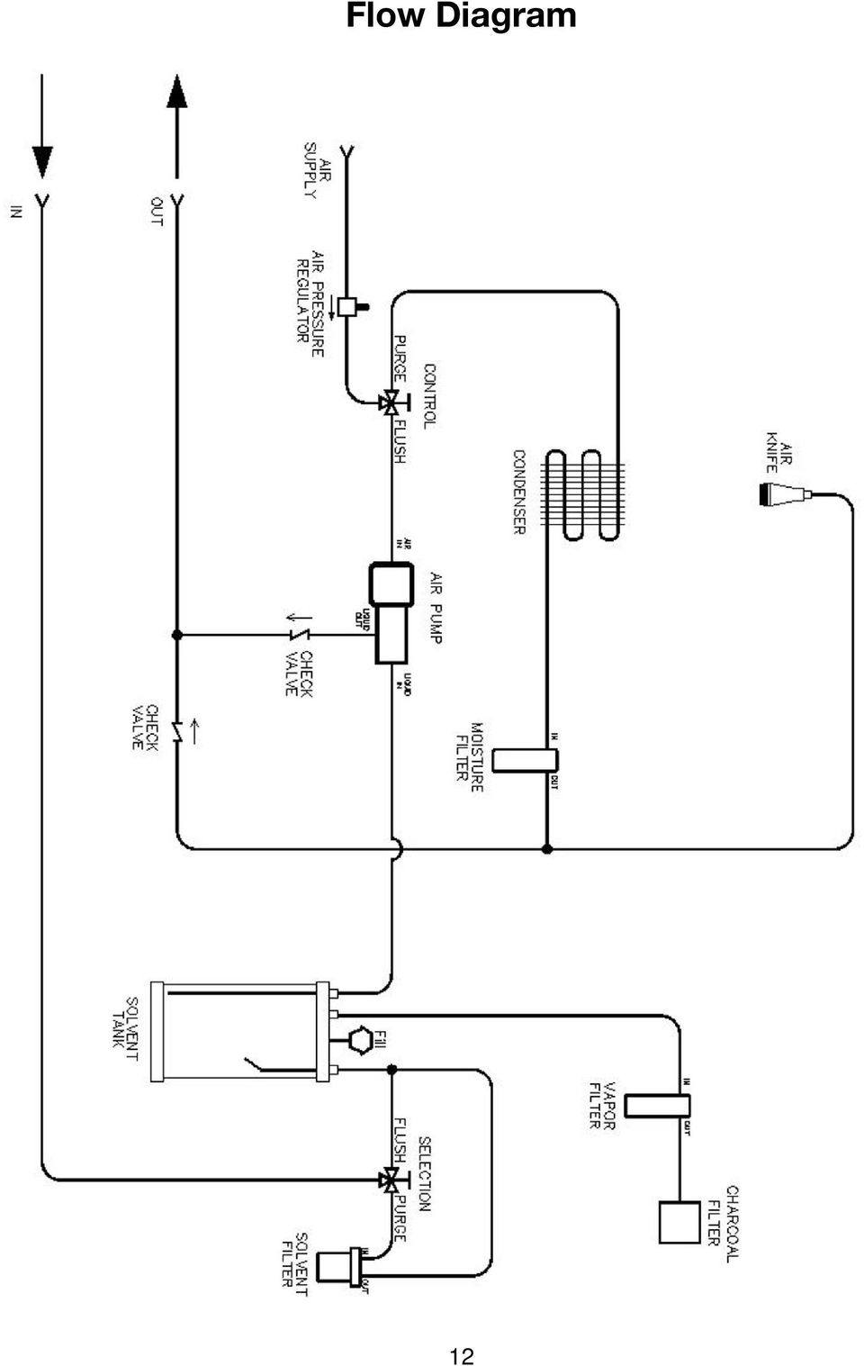
12 Flow Diagram 12
13 ACF Unit Usage and Replacement Log Record Date of Vehicle Flush and Spin-On Date Charcoal Air Date Vapor Separation Date Coalescing Record Date of Vehicle Flush and Spin-On Date Charcoal Air Date Vapor Separation Date Coalescing 13

14 ACF Unit Usage and Replacement Log Record Date of Vehicle Flush and Spin-On Date Charcoal Air Date Vapor Separation Date Coalescing Record Date of Vehicle Flush and Spin-On Date Charcoal Air Date Vapor Separation Date Coalescing 14

15 MSS One-Year Limited Warranty (Applies only to equipment owned and operated in North America) During the One-Year Warranty period, MAHLE Aftermarket Inc., Service Solutions (MSS) is solely responsible for costs associated with parts and labor for repairs needed due to defects in material and/or workmanship. MSS is not responsible for the costs associated with repairs needed due to improper use or a lack of normal maintenance. MSS s goal is to provide a timely turn-around of the covered product requiring warranty repair. The Customer is responsible to ASSIST AND PARTICIPATE with MSS Technical Support in the over-the-phone diagnosis process of: A) Determining that a legitimate failure has occurred and that the complaint is not just the result of inadequate training and/or improper use that could be easily remedied by over-the-phone instructions. B) Determining the nature of the failure and that it is reasonable for MSS Technical Support to judge over the phone that the failure is warrantable. C) Determining the parts necessary to make the repairs so that those parts can be shipped via the appropriate expedited method at the expense of MSS if the failure is warrantable. During the One Year Warranty period for failures that are deemed by MSS to be warrantable, MSS is solely responsible for providing Field Repair Service within a reasonable period of time after a warrantable failure is reported. Field Repair Service is generally available in all areas within 150 miles of major metropolitan areas of the US. A reasonable period of time will depend on the location of the customer and the time of the year. MSS maintains a large network of Service Providers in the US. When Field Repair Service is needed, in most locations near a major US metropolitan area, and during most times of the year, a reasonable period of time for Field Service is 24 to 48 hours after parts are received by the Customer. Since repair parts from MSS will normally arrive 24 to 48 hours after the Customer reports a failure, the Customer may at his sole option and discretion, choose to make the necessary repairs, with over-thephone support from MSS Technical Support so as to minimize downtime. In such case, MSS will compensate the Customer or the Customer s employee as appropriate for the time necessary to make repairs if the failure is covered by warranty. It is the Customer s responsibility to maintain the MSS Equipment according to instructions in the MSS Operation Manual for the covered product as well as to operate the equipment in a commercially reasonable manner as generally described in the MSS Operation Manual. MSS provides free Technical Support over toll-free telephone lines in the US to assist the customer in this regard for the life of the covered product. The Customer should review the legal Warranty Disclaimer for more details of coverage and limitations. Ancillary accessories such as Refrigerant Identifiers, Leak Detector Lights and Leak Detectors must be returned to MSS for repair or replacement with a new or refurbished unit, at MSS s sole discretion, in case of a warrantable defect. 15

16 WARRANTY DISCLAIMER FOR PRODUCTS OF MAHLE AFTERMARKET INC., SERVICE SOLUTIONS (MSS) 1. MSS'S WARRANTY 6. EXCLUSIONS (Continued) This is to certify that MAHLE Aftermarket Inc., MSS Division warrants to the first retail purchaser only, the described new product manufactured by it to be free from defects in materials and workmanship, when properly maintained, under normal use and service for a period of ONE YEAR. All spare parts supplied by MSS will have a 90 day warranty. This warranty includes the reasonable cost of parts and materials as well as non-overtime labor. MSS shall be the sole judge of whether failure is warrantable. 2. PURCHASER'S REMEDY Purchaser's sole and exclusive remedy under this warranty shall be limited to the repair or replacement, at MSS s option, of any defective part of the product. Purchaser shall call MSS Technical Support who will assist Purchaser in diagnosing the problem and, if deemed necessary, will immediately ship replacement parts for installation by Purchaser if so requested. If Purchaser requests Factory service, repairs under this warranty shall only be made at a location designated by MSS. 3. DURATION This warranty will expire one year from date of delivery to the first retail purchaser. 4. PURCHASER'S DUTIES (a) (b) Register product with MSS by returning completed Warranty Registration within 90 days of delivery of unit. Transportation Expense: Transportation expenses to and from the MSS's facility are to be borne by the Purchaser. (f) (g) (h) (i) (j) (k) (l) (m) Parts, accessories or other items manufactured by others which are used or installed on the product as a result of Purchaser's specifications. Used items furnished by the Purchaser for installation on the product. Items which are not defective, but must be replaced during the warranty period as a result of fair wear and tear or scheduled maintenance. Hoses, field service couplings, adapters, gaskets and O-rings carry a ninety day warranty. s, vacuum pump oil and compressor oil are considered consumables and are not covered by any warranty. The Warranty may be considered void if evidence of any refrigerant system sealer is found in any of the internal components of an MSS recovery/recycling machine. Refrigerant loss is not covered. The Purchaser is responsible for detecting system leaks and advising MSS of same if warrantable repair is required. Calibration of equipment, having integrated solid-state controls and load cells for weighing fluids, is not covered beyond the initial setup and commissioning of the equipment. The requirement for calibration of load cell controls is considered normal maintenance and is dependent on many factors, the main one being the care taken when moving the equipment about the shop. (c) Notice of breach: Purchaser shall give written notice to MSS of any alleged refusal or failure of MSS to repair or replace as promised by this warranty no later than fifteen days after the Purchaser learns of such alleged failure or refusal. 5. DISCLAIMER THE EXPRESS WARRANTY HEREIN IS IN LIEU OF ANY AND ALL OTHER WARRANTIES, EXPRESSED OR IMPLIED. NO IMPLIED WARRANTY OF MERCHANTABILITY IS MADE AND THERE ARE NO WARRANTIES WHICH EXTEND BEYOND THE DESCRIPTION ON THE FACE HEREOF. 6. EXCLUSIONS The warranty and obligations stated here shall not apply to: (a) (b) (c) (d) (e) Any product not registered within 90 days of delivery. Any product repaired or altered without prior approval of MSS so as to affect adversely its stability or reliability. Any product subjected to misuse, abuse or accident as well as products used in a manner contrary to written instructions or normal operating procedure. Any damage to product during original shipment or subsequent shipments to MSS s facility for service. Portions of products which are subject to warranties, if any, given by their manufacturers. MSS does not adopt these warranties. 7. EXCLUSION OF LOST PROFITS AND OTHER CONSEQUENTIAL DAMAGES MSS will have no liability for any lost profit, cargo loss, usage loss or other consequential damages alleged to have been caused by any defect in the product or any failure of MSS to meet any obligation under this agreement including the obligation to repair and replace set forth in Paragraph LIMITATIONS OF ACTIONS No action for breach of this warranty shall commence more than one year after the accrual of the cause of action. 9. MERGER This written warranty is the complete, final and exclusive agreement of the parties with respect to the quality or performance of the goods and any and all warranties and representations, except warranty extensions, if any, in writing as applicable. 10. NO ORAL MODIFICATIONS OR WAIVERS No modification of this warranty or waiver of its terms shall be binding on either party unless approved in writing by an authorized official of the parties. 11. GOVERNING LAW This warranty and the rights and duties of the parties under this warranty shall be governed by the law of Pennsylvania, the state of the MSS s principle place of business. MAHLE Aftermarket Inc., Service Solutions 10 Innovation Drive York, PA USA

17

Failure to comply with the following cautions and warnings could cause equipment damage and personal injury.
 1.0 IMPORTANT RECEIVING INSTRUCTIONS Visually inspect all components for shipping damage. Shipping Damage is not covered by warranty. If shipping damage is found, notify carrier at once. The carrier is
MODEL G300 BRAKE BLEEDER
 MODEL G300 BRAKE BLEEDER Installation, Operation & Repair Parts Information Branick Industries, Inc. 4245 Main Avenue P.O. Box 1937 Fargo, North Dakota 58103 REV060616 P/N: 81-0035G 1 THIS PAGE INTENTIONALLY
GAS SAFETY PRECAUTIONS
 GAS SAFETY PRECAUTIONS Instructions on what to do when a user smells gas can be obtained from the local gas supplier. These instructions must be posted in a prominent location where the unit is to be operated.
Refrigerant Charging Unit ICOGD. 020AH1000 Operating Manual. FR.8.2.4-09 İ-COLD 12.03.2014 Rev. 00
 E Refrigerant Charging Unit ICOGD 020AH1000 Operating Manual FR.8.2.4-09 İ-COLD 12.03.2014 Rev. 00 Contents Technical Specifications... 20 Safety... 21 A/C System... 22 Components... 23 Control Panel...
Failure to comply with the following cautions and warnings could cause equipment damage and personal injury.
 1.0 IMPPORTANT RECEIVING INSTRUCTIONS Visually inspect all components for shipping damage. Shipping Damage is not covered by warranty. If shipping damage is found, notify carrier at once. The carrier is
FLUSHMATE FLUSHMATE FLUSHOMETER - TANK SYSTEM. Owner s Service Manual 503 and 504 Series
 Owner s Service Manual 503 and 504 Series FLUSHMATE FLUSHOMETER - TANK SYSTEM 503 504 FLUSHMATE A Division of Sloan Valve Company 30075 Research Drive New Hudson, MI 48165 800-533-3460 248-446-5300 http://www.flushmate.com
Bottom Loading Water Dispenser
 Bottom Loading Water Dispenser Model # 601000 TO REDUCE THE RISK OF INJURY AND PROPERTY DAMAGE, USER MUST READ THIS MANUAL BEFORE ASSEMBLING, INSTALLING & OPERATING DISPENSER. SAVE THIS MANUAL FOR FUTURE
PAINT SPRAY GUN WASHER
 PAINT SPRAY GUN WASHER 94996 ASSEMBLY AND OPERATING INSTRUCTIONS Visit our website at: http://www.harborfreight.com Read this material before using this product. Failure to do so can result in serious
Ultraviolet Germicidal Lamps Owner s Manual MODELS 1910 & 1930
 Ultraviolet Germicidal Lamps Owner s Manual MODELS 1910 & 1930 WARNING Ultraviolet light is harmful to eyes and skin. Never look at light produced by this lamp. Unplug lamp before servicing. Electrical
Failure to comply with the following cautions and warnings could cause equipment damage and personal injury.
 1.0 IMPORTANT RECEIVING INSTRUCTIONS Visually inspect all components for shipping damage. Shipping Damage is not covered by warranty. If shipping damage is found, notify carrier at once. The carrier is
MODEL #12006. Introduction
 THE ORIGINAL PECO POWER SPRAYER PECO OWNER S MANUAL MODEL #12006 (Q0080) Revised: 1/8/2014 PECO POWER SPRAYER MODEL #12006 TABLE OF CONTENTS SECTION PAGE SECTION PAGE INTRODUCTION - - - - - - - - - - -
VW TDI (Golf, Jetta, New Beetle) Upgrade Turbocharger
 Upgrade Turbocharger") VW TDI (Golf, Jetta, New Beetle) Upgrade Turbocharger Bill of Materials & Precautions 1.9L TDI BEW-code: 2003.5-2006 A4 New Beetle TDI 2003.5-2006.0 A4 Golf 2003.5-2005.0 A4 Jetta Parts List Item Description
VW TDI (Golf, Jetta, New Beetle) Upgrade Turbocharger Bill of Materials & Precautions 1.9L TDI BEW-code: 2003.5-2006 A4 New Beetle TDI 2003.5-2006.0 A4 Golf 2003.5-2005.0 A4 Jetta Parts List Item Description
Propane Conversion Kit PROPANE CONVERSION KIT INSTALLATION MANUAL
 Propane Conversion Kit Supersedes: 145.25-IOM2 (708) Form 145.25-IOM2 (908) PROPANE CONVERSION KIT INSTALLATION MANUAL "LPKIT " - PROPANE CONVERSION KIT Kits are available for field conversion from natural
Air Conditioning Systems Warranty Manual. Version 1.8
 Air Conditioning Systems Warranty Manual Version 1.8 1/2015 Air Conditioning System Warranty Contents Purpose 4 External Distribution... 4 Policies 5 Warranty Policy Overview... 5 Warranty Period... 5
SE-100-1, SE-200-1, SE-500-1, and SE-1000-1 AIR CHAMP PRODUCTS. User Manual SE BRAKE MODELS: (i) MTY (81) 83 54 10 18 ventas@industrialmagza.
 MTY (81) 83 54 10 18 ventas@industrialmagza.") AIR CHAMP PRODUCTS User Manual SE BRAKE MODELS: SE-00-, SE-200-, SE-500-, and SE-000- (i) FORM NO. L-20084-E-040 In accordance with Nexen s established policy of constant product improvement, the specifications
AIR CHAMP PRODUCTS User Manual SE BRAKE MODELS: SE-00-, SE-200-, SE-500-, and SE-000- (i) FORM NO. L-20084-E-040 In accordance with Nexen s established policy of constant product improvement, the specifications
Air vacuum pump with r134a & r12/22
 Air vacuum pump with r134a & r12/22 Model 96677 Set up And Operating Instructions To prevent explosion, serious injury, and death: Service of air conditioning systems must be done only by trained and experienced
USER MANUAL. Bottom Loading Bottled Water Dispenser SAVE THIS MANUAL FOR FUTURE USE. Model # 900172
 Model # 900172: Page 1 USER MANUAL Bottom Loading Bottled Water Dispenser Model # 900172 TO REDUCE THE RISK OF INJURY AND PROPERTY DAMAGE, USER MUST READ THIS MANUAL BEFORE ASSEMBLING, INSTALLING & OPERATING
Recharge Procedure for Telemark TVP-2000 and TVP-3500
 Recharge Procedure for Telemark TVP-2000 and TVP-3500 Required items: 1.) Refrigeration service manifold. 2.) Charge recovery system. 3.) Dry nitrogen gas. If a high pressure cylinder is used, a pressure
Rexroth Hydraulic Pump A10VO Series User Manual
 Rexroth Hydraulic Pump A10VO Series User Manual Rexroth Hydraulic pump A10VO Series User Manual Revised 5/1/2009 Page 1 of 12 Functional Purpose This pump is preferred over a fixed displacement (gear)
Extrusion Flo-Valve INSTRUCTIONS-PARTS LIST. 3000 psi (210 bar) Maximum Working Pressure. Model 204 355, Series K. Rev.
 Maximum Working Pressure. Model 204 355, Series K. Rev.") INSTRUCTIONS-PARTS LIST INSTRUCTIONS This manual contains important warnings and information. READ AND KEEP FOR REFERENCE. 306 586 Rev. D Supercedes B Extrusion Flo-Valve Model 204 355, Series K 3000 psi
INSTRUCTIONS-PARTS LIST INSTRUCTIONS This manual contains important warnings and information. READ AND KEEP FOR REFERENCE. 306 586 Rev. D Supercedes B Extrusion Flo-Valve Model 204 355, Series K 3000 psi
MaxiMist Spraymate By Earlex
 MaxiMist Spraymate By Earlex Distributed exclusively by Spray Tan Direct www.spraytandirect.com PART # DESCRIPTION 1 Air cap ring L0215 2 Air cap L0205 3 Spray direction plate L0206 4 Solution nozzle/spray
GM DURAMAX LMM 09-10 Fuel Pickup Kit Installation Guide
 Pacific Performance Engineering, Inc. www.ppediesel.com GM DURAMAX LMM 09-10 Fuel Pickup Kit Installation Guide Technical Support (714) 985-4825 Rev: 3/30/11 v5 DISCLAIMER OF LIABILITY This agreement sets
Ozone Generator Manual
 ENMET Corporation PO Box 979 Ann Arbor, MI 48106-0979 Ozone Generator Manual 80003-118 MCN-282, 05/14/04 Table of Contents 1.0 INTRODUCTION... 1 1.1 Unpack...1 1.2 Check Order...1 1.3 Serial Numbers...1
In-Line Filters and Coalescers with Automatic Drains
 Instructions/Parts In-Line Filters and Coalescers with Automatic Drains 310611G EN Air Filter with Automatic Drain Part No. 22601, Series B Maintenance To maintain maximum filtering efficiency and to avoid
FASCINATION 700 HVLP TANNING PRO SYSTEM USER MANUAL
 FASCINATION 700 HVLP TANNING PRO SYSTEM USER MANUAL Congratulations on choosing the Fascination 700 HVLP Tanning Pro System! Your system includes the following items: 1 Fascination 700 HVLP Tanning Pro
Ceiling Mount Air Handler Manual
 www.surna.com 303.993.5271 Ceiling Mount Air Handler Manual Models: CMAH12, CMAH18, CMAH24, CMAH30, CMAH36, CMAH48, CMAH60 Revised: September 2014 Table of Contents Warranty Information 4 Limited Warranty
Operations and Maintenance Manual
 Operations and Maintenance Manual FOR MODELS 1234XL 1090XL 1095XL P/N 99971-SP Rev. 1/98 Table of Contents Set-Up...1 Introduction... 1 Unit Set-Up... 1 White Industries Models...1 1090XL Panel and 1234XL
VW TDI (Golf, Jetta, New Beetle) Upgrade Turbocharger
 Upgrade Turbocharger") VW TDI (Golf, Jetta, New Beetle) Upgrade Turbocharger Bill of Materials & Precautions.9L TDI BEW-code: 2003.5-2006 A4 New Beetle TDI 2003.5-2006.0 A4 Golf 2003.5-2005.0 A4 Jetta Item 2 Parts List Description
VW TDI (Golf, Jetta, New Beetle) Upgrade Turbocharger Bill of Materials & Precautions.9L TDI BEW-code: 2003.5-2006 A4 New Beetle TDI 2003.5-2006.0 A4 Golf 2003.5-2005.0 A4 Jetta Item 2 Parts List Description
TERMS AND CONDITIONS 1 CONTRACT INFORMATION
 SUMMARY These terms and conditions govern your purchase of SocketCare for the Covered Products and for the Contract Term as defined herein. SocketCare is a service program that provides for the repair
tire inflator with pressure gauge
 tire inflator with pressure gauge Model 95583 Assembly And Operation Instructions Due to continuing improvements, actual product may differ slightly from the product described herein. 3491 Mission Oaks
Warranty Terms. QLogic-provided cables, optics and other accessories are warranted for ninety (90) days from date of purchase.
 days from date of purchase.") Warranty Terms QLogic Corporation ("QLogic") provides the following warranties to the original purchaser of QLogic products from QLogic or, in the case of resale, to the initial end user customer (the
Warranty Terms QLogic Corporation ("QLogic") provides the following warranties to the original purchaser of QLogic products from QLogic or, in the case of resale, to the initial end user customer (the
1 / 4 IN. FFL x 4 FT. 9 IN. 1 / 2 IN. ACME x 4 FT. 9 IN. Gauge Accuracy +/-2% Set includes Quick Disconnect Valves
 Specifications Blue (Low) Gauge 0-120 PSI Blue Hose 1 / 4 IN. FFL x 4 FT. 9 IN. Red (High) Gauge 0-500 PSI Red Hose 1 / 4 IN. FFL x 4 FT. 9 IN. Yellow Hose 1 / 2 IN. ACME x 4 FT. 9 IN. Gauge Accuracy +/-2%
Installation Instructions
 7.3L & 6.0L 5/8 FUEL TANK PICKUP KIT Fits 94-07 7.3L & 6.0L Powerstroke Diesel Trucks & Excursions Installation Instructions These instructions are intended simply to be a guide for the installation of
Overview PARTS LIST. B. Lever mounting base C. Flush handle assembly D. Grey/Blue float stop E. Grey float (Full Flush) F. Flush valve washer
 F. Flush valve washer") Overview READ ENTIRE INSTRUCTIONS BEFORE STARTING INSTALLATION PARTS LIST A. Flush valve B. Lever mounting base C. Flush handle assembly D. Grey/Blue float stop E. Grey float (Full Flush) F. Flush valve
Overview READ ENTIRE INSTRUCTIONS BEFORE STARTING INSTALLATION PARTS LIST A. Flush valve B. Lever mounting base C. Flush handle assembly D. Grey/Blue float stop E. Grey float (Full Flush) F. Flush valve
Instructions. Complete RPS 2900 Pump Kit for RoadLazer RoadPak Line Striping System 3A1304A ENG. Pressure Relief Procedure.
 Instructions Complete RPS 2900 Pump Kit for RoadLazer RoadPak Line Striping System 3A1304A ENG Model 24G766 Important Safety Instructions For complete warnings and safety instructions see RoadLazer RoadPak
In-Tank Fuel Pump Installation Instructions (Read Carefully Before Starting Project)
") Granatelli Motor Sports, Inc. 1000 Yarnell Place Oxnard, CA 93033-2454 805-486-6644 (Phone) 805-486-6684 (Fax) Hours: M-F 8AM-5PM (PST) www.granatellimotorsports.com/techsupport.htm [email protected]
Granatelli Motor Sports, Inc. 1000 Yarnell Place Oxnard, CA 93033-2454 805-486-6644 (Phone) 805-486-6684 (Fax) Hours: M-F 8AM-5PM (PST) www.granatellimotorsports.com/techsupport.htm [email protected]
OP300S / OP350 2:1 RATIO TRANSFER PUMP
 OP300S / OP350 2:1 RATIO TRANSFER PUMP OPERATING MANUAL WITH PARTS IDENTIFICATION Copyright 2013 International Pump Manufacturing, Inc. This manual contains IMPORTANT WARNINGS and INSTRUCTIONS. Read and
8 ton air/hydraulic long ram jack
 8 ton air/hydraulic long ram jack Model 94562 Set up and Operating Instructions Visit our website at: http://www.harborfreight.com Read this material before using this product. Failure to do so can result
6 & 12 Volt Battery and Systems Tester with 100 Amp Load
 6 & 12 Volt Battery and Systems Tester with 100 Amp Load Form No. 841-731 -000 DESCRIPTION This Load Tester tests 6 or 12 volt automotive-size lead-acid batteries under load. It will also test 6 or 12
Use & Care. of your Iron. All about the TA B L E O F C O N T E N T S. USA and Canada 1-888-845-7330
 All about the Use & Care of your Iron Important Safeguards... 2 Iron Safety Instructions... 3 Parts and Features...4 TA B L E O F C O N T E N T S Using Your Iron...6 Cleaning and Maintenance... 8 Warranty...9
MP-4V Heavy Duty Riveter / 39048
 MP-4V Heavy Duty Riveter / 39048 This newly designed heavy-duty air/hydraulic riveter is ergonomically designed with the professional in mind. The light weight 3.7 lbs. well balanced MP-4V includes a Vacuum
el-720 Carbon Dioxide Gas Leak Detector User s Guide
 el-720 Carbon Dioxide Gas Leak Detector User s Guide Congratulations on the purchase of the AccuTools el-720 Carbon Dioxide Gas Leak Detector, the most technologically advanced instrument of its kind.
RT-200 HI-TEST ROPE TESTER
 RT-200 HI-TEST ROPE TESTER Operating & Instruction Manual HD ELECTRIC COMPANY 1 4 7 5 L A K E S I D E D R I V E W A U K E G A N, I L L I N O I S 6 0 0 8 5 U. S. A. P H O N E 8 4 7. 4 7 3. 4 9 8 0 FA X
RGC-IR Remote Gas Calibrator for IR400
 Remote Gas Calibrator for IR400 The information and technical data disclosed in this document may be used and disseminated only for the purposes and to the extent specifically authorized in writing by
SunMaxx Solar Filling Station Operating Instructions
 SunMaxx Solar Filling Operating Instructions Content 1. Declaration of conformity... 2 2. Introduction... 2 3. Transportation and unpacking... 4 4. Mounting and commissioning... 5 5. End of operation...
LIFT N RACK PRO OPERATING & INSTALLATION GUIDE 5500 Lb. LIFT CAPACITY
 LIFT N RACK PRO OPERATING & INSTALLATION GUIDE 5500 Lb. LIFT CAPACITY IMPORTANT: READ THIS MANUAL BEFORE IN-STALLING, OPERATING OR MAINTAINING YOUR LIFT. Chassis Liner Company Sales Office Toll Free: 800-242-2448
15GAL STEEL OIL DRAIN WITH 110V PUMP
 15GAL STEEL OIL DRAIN WITH 110V PUMP OWNER S MANUAL WARNING: Read carefully and understand all ASSEMBLY AND OPERATION INSTRUCTIONS before operating. Failure to follow the safety rules and other basic safety
Installation Operation Maintenance Troubleshooting
 Installation Operation Maintenance Troubleshooting Version 3, 2.1, June/09 Apr/09 1416 1402 Table of Contents Important information 2 Weights & Dimensions 3 Operator s Instructions 4 Flow Diagram 5 Purging
DTM04 TANK MONITOR DTM08 TANK MONITOR Dtm12 TANK MONITOR. Installation and Operation Manual
 DTM04 TANK MONITOR DTM08 TANK MONITOR Dtm12 TANK MONITOR Installation and Operation Manual 1 ENGLISH Safety Instructions 2 Features 2-3 Specifications 3 Installation 4-5 Wiring Diagrams 6-7 Warranty 8
PNEUMATIC PLANISHING HAMMER
 PNEUMATIC PLANISHING HAMMER 94847 ASSEMBLY AND OPERATING INSTRUCTIONS Due to continuing improvements, actual product may differ slightly from the product described herein. Distributed Exclusively by Harbor
VPCCCare. Virtual PC Center Service Warranty Program
 VPCCCare Virtual PC Center Service Warranty Program Proprietary Notice and Liability Disclaimer The information disclosed in this document, including all designs and related materials, is the valuable
American Dish Service
 Effective: June, 2008 American Dish Service ADS GLASSWASHER MODEL: ASQ OWNERS MANUAL 900 Blake Street Edwardsville, Kansas 66111 (913)-422-3700 05/08 IMPORTANT: American Dish Service provides this information
 KEY WEST BOATS INC. WARRANT POLICY FOR 2010 MODEL BOATS WHAT IS COVERED: KEY WEST BOATS, INC. MANUFACTURER warrants to the retail purchase of its 2010 and later model year products, which are purchased
FOR THE FOLLOWING MODELS: EE-8075W EE-8075O EE-8075R EE-8075BK
 FIREPLACE HEATER FOR THE FOLLOWING MODELS: EE-8075W EE-8075O EE-8075R EE-8075BK If you have any questions about the operation of your fireplace heater, please contact Crane Customer Care. Toll Free: 888-599-0992
2014 EBR MOTORCYCLE LIMITED WARRANTY
 2014 EBR MOTORCYCLE LIMITED WARRANTY 24 Months/Unlimited Miles EBR warrants for any new 2014 EBR motorcycle that an authorized EBR dealer will repair or replace without charge any parts found under normal
ROUSH PERFORMANCE - Limited Warranty
 ROUSH PERFORMANCE - Limited Warranty ROUSH PARTS AND ACCESSORIES* WHO IS COVERED ROUSH's warranty obligations for ROUSH Parts and Accessories (individually and collectively Part(s) ) is limited to defects
Air conditioning service unit CAAS500
 Air conditioning service unit CAAS500 OPERATING INSTRUCTIONS TES1453 09/2004 C A A S 5 0 0 O P E R A T I N G I N S T R U C T I O N S P a g e 2 IMPORTANT THIS MANUAL CONTAINS INFORMATION PERTINENT TO OPERATOR
PET-10 INSTRUCTION MANUAL PRESSURE TANK
 INSTRUCTION MANUAL PRESSURE TANK PET-10 This manual contains IMPORTANT WARNINGS and INSTRUCTIONS. Equipment in this manual is exclusively for painting purposes. Do not use for other purposes. The operator
Flat Bottom Long Ram Hydraulic Jack
 Flat Bottom Long Ram Hydraulic Jack 3 Ton 8 Ton 36468 36469 ASSEMBLY & OPERATING INSTRUCTIONS 349 Mission Oaks Blvd., Camarillo, CA 930 Visit our Web site at http://www.harborfreight.com TO PREVENT SERIOUS
Subject: 2005 Air Conditioning Service Guidelines
 Date: June 27, 2005 Bulletin Number: 05D-J-114 To: DDG Headquarters and Branches and Jobbers Category: Service From: Steve Sigg, Product Service and Training Line(s): 10 and 15 Subject: 2005 Air Conditioning
Portable Air Conditioner. OWNER S MANUAL Read these instructions before use. Model: MF08CESWW. Voltage rating: 115V~60Hz Power rating : 800W
 MODE ALARM Portable Air Conditioner OWNER S MANUAL Read these instructions before use 8 Model: MF08CESWW Voltage rating: 115V~60Hz Power rating : 800W Customer Support : 1-800-474-2147 For product inquiries
Installation and Maintenance Instructions
 Installation and Maintenance Instructions Limited One Year Warranty T&S warrants to the original purchaser (other than for purposes of resale) that such product is free from defects in material and workmanship
Terms and Conditions for Purchase Orders for Recycling Materials
 Terms and Conditions for Purchase Orders for Recycling Materials This Agreement is made by and between AEROJET-GENERAL CORPORATION, an Ohio corporation with a place of business at Rancho Cordova, California
Flushing and Cleaning the A/C System
 Flushing and Cleaning the A/C System Once an AC system has been contaminated or has suffered a failure, the most important part of the AC service to restore the cooling performance to the system = FLUSHING
UNIVERSAL LUMBAR INSTALLATION INSTRUCTIONS
 UNIVERSAL LUMBAR INSTALLATION INSTRUCTIONS CONTENTS Parts List... 2 Parts Diagram... 2 Helpful Hints... 3 Installation... 4 Operation and Troubleshooting Guide... 6 Warranty Information... 8 Form #3132,
EPSON PreferredSM. Toll-Free Phone Number. Priority Technical Support. Security and Peace of Mind. On-Site Repair. Epson Stylus Pro 7900/9900
 EPSON PreferredSM Limited Warranty Program for the Epson Stylus Pro 7900/9900 Toll-Free Phone Number Priority Technical Support Security and Peace of Mind On-Site Repair 2 Welcome and Congratulations Congratulations
Table of Contents WARNING SYMBOLS AND DEFINITIONS
 Table of Contents SAFETY INSTALLATION OPERATION MAINTENANCE Safety... 2 Specifications... 4 Installation... 5 Operation... 8 WARNING SYMBOLS AND DEFINITIONS Maintenance... 9 Parts List and Assembly Diagram...
Name of Equipment Silver King Model SKMCD1P/C1. This equipment chapter is to be inserted in the appropriate section of the Equipment Manual.
 Name of Equipment Silver King Model SKMCD1P/C1 This equipment chapter is to be inserted in the appropriate section of the Equipment Manual. Manufactured exclusively for McDonald s By Silver King Refrigeration,
Start Here. 3200 Series. All-in-One Printer. Print Copy Scan. Includes Information on the: ESP 3250 All-in-One Printer ESP 3260 All-in-One Printer
 Start Here All-in-One Printer 3200 Series MS SD/HC MMC Print Copy Scan Includes Information on the: ESP 3250 All-in-One Printer ESP 3260 All-in-One Printer Note: A USB 2.0 cable is required to connect
POWER GEAR SLIDE OUT MANUAL
 POWER GEAR SLIDE OUT MANUAL Operation Guide FLUSH FLOOR SLIDE OUT SYSTEM FOR AMERICAN COACH PRODUCTS 82 S0220 01 Rev. 1 AMERICAN COACH SLIDE OUT MANUAL FLUSH FLOOR SYSTEM TABLE OF CONTENTS SECTION PAGE
Operator s Manual. Pressure Injection Cell Model PC8500. Congratulations! Contents
 Operator s Manual Pressure Injection Cell Model PC8500 Congratulations! Congratulations on your purchase of a Next Advance Pressure Injection Cell. Please read this operator s manual which explains proper
SERIES 12-600 VOLT ELECTRIC INSTANTANEOUS WATER HEATER FOR EMERGENCY SAFTEY EQUIPMENT INSTALLATION AND OWNERS MANUAL REQUIRED MANTENANCE
 Eemax Inc., 353 Christian Street, Oxford, CT 06478 1 E ema X SERIES 12-600 VOLT ELECTRIC INSTANTANEOUS WATER HEATER FOR EMERGENCY SAFTEY EQUIPMENT INSTALLATION AND OWNERS MANUAL REQUIRED MANTENANCE WARNING
VK-250 WARRANTY REGISTRATION FORM
 VK-250 WARRANTY REGISTRATION FORM Unit Serial Number: Customer Name: Address: Date of Purchase: Purchased From: Dealer Name: Address: IMPORTANT NOTE: In order to receive the full five year product warranty,
Compressor Service & Maintenance Manual
 Compressor Service & Maintenance Manual C Series COMPRESSOR (D)C1103 (D)C1203 (D)C2106 (D)C2206 (D)C3210 Copyright 2006 DCI. All Rights Reserved. 92311, Rev. C, 08/13 1 C1000 Series Service & Maintenance
AM/FM Emergency Weather Radio/Light With Hand Crank Back-Up Power
 VEC173 ONE YEAR LIMITED WARRANTY PROGRAM This limited warranty program is the only one that applies to this product, and it sets forth all the responsibilities of Vector Manufacturing, regarding this product.
3 WATT LED SPOTLIGHT Model No. SLM - 3801
 3 WATT LED SPOTLIGHT Model No. SLM - 3801 OWNER'S MANUAL Customer Service Tel: 1-800-268-3319 Superex Canada Ltd, Toronto,M2H 3B8 Made in China Table of Contents A). Important Safety Instructions B). Charging
SINGLE STAGE INLINE FIRE PUMP
 MODEL 383 SINGLE STAGE INLINE FIRE PUMP INSTRUCTION AND REPAIR MANUAL NOTE! To the installer: Please make sure you provide this manual to the owner of the equip ment or to the responsible party who maintains
Fluid Regulator. Instructions Parts List 306563L LOW PRESSURE
 Instructions Parts List LOW PRESSURE Fluid Regulator 306563L For accurate, positive control of fluid pressure to one spray gun, dispensing valve, or atomizing head. For professional use only. 250 psi (18
Limited Warranty Information. Contents: Golf Car Limited Warranty Part & Accessories Limited Warranty
 Limited Warranty Information Contents: Golf Car Limited Warranty Part & Accessories Limited Warranty Only applicable in the United States Version no. 1 / Release date: 7 th of April 2010 Warranty summary
The Storm 20-Gallon Wet/Dry Vac
 Mercury Floor Machines, Inc. New Equipment Warranty Limited Warranty Mercury Floor Machines, Inc. warrants new equipment against defects in material and workmanship under normal use and service to the
2-3 SAS/SATA II HDD Canister USER S MANUAL XC-23D1-SA10-0-R. Document number: MAN-00076-A
 2-3 SAS/SATA II HDD Canister XC-23D1-SA10-0-R USER S MANUAL Document number: MAN-00076-A ii Preface Important Information Warranty Our product is warranted against defects in materials and workmanship
PALLET JACK - 2.5 TON
 PALLET JACK - 2.5 TON 39939 SET UP AND OPERATING INSTRUCTIONS Visit our website at: http://www.harborfreight.com Read this material before using this product. Failure to do so can result in serious injury.
FJ2. 2 Ton Trolley Floor Jack Assembly & Operating Instructions
 FJ2 2 Ton Trolley Floor Jack Assembly & Operating Instructions READ ALL INSTRUCTIONS AND WARNINGS BEFORE USING THIS PRODUCT. This manual provides important information on proper operation & maintenance.
12V Portable Diaphragm Compressor Operating and Maintenance Instructions
 12V Portable Diaphragm Compressor Operating and Maintenance Instructions (Part No. DC2) Part No. Serial Number Date Purchased Table of Contents Page Safety Messages...2 Guidelines for Product Use...2 Operation
Multi-Pitch Pitching Machine USER MANUAL
 Multi-Pitch Pitching Machine USER MANUAL TABLE OF CONTENTS Thank you for purchasing the Cimarron Multi-Pitch Pitching Machine. The Cimarron Multi-Pitch Pitching Machine is a high performance pitching machine
FLUSHOMETER - TANK SYSTEM
 Owner s Service Manual 501-A Series FLUSHOMETER - TANK SYSTEM 501-A Series FLUSHMATE 501-A SERIES (D) (E) (C) 2 3 (B) 1 4 (F) (A) 6 5 List of Components for 501-A Series*: 1. Lower Supply Group w/hose
AIRCRAFT FUEL PUMP & PARTS PRICE LIST
 AIRCRAFT FUEL PUMP & PARTS PRICE LIST RELEASE DATE» January 2, 2013 AUTHOR» HET Sales Department REV» Original: Formatted to HET Design Standards Hartzell Engine Technologies (HET) is the leading OEM supplier
ROUGHNECK II Pumpless Drain
 SERVICE BULLETIN SB4027 Rev. I 1/11 For Used Oil Only ROUGHNECK II Pumpless Drain Model #4110-022 FOR USED OIL ONLY (Black) For Antifreeze Only Model #4110-023 FOR USED ANTIFREEZE ONLY (Green) Patent #
OWNERS MANUAL FOR CORDLESS INFLATOR AIR260
 OWNERS MANUAL FOR CORDLESS INFLATOR AIR260 POWER SUPPLY OUTLET: AIR OUTPUT: BATTERY: RECHARGING TIME: WEIGHT: DIMENSIONS: FUSE: LIGHT BULB: SPECIFICATIONS DC 12V 15 AMP 180W MAX 260 PSI MAX PRESSURE SEALED
Panini Maintenance Program My Vision X STANDARD WARRANTY-
 Panini Maintenance Program My Vision X STANDARD WARRANTY- Panini warrants, to its customers, its authorized Resellers customers, and no others, that all My Vision X Branch Image Scanners ( My Vision X
MODEL VG08008 CONTENT PACKING LIST / TOOLS NEEDED PANEL DIMENSIONS FITTINGS / TECHNICAL DATA WALL/CORNER INSTALLATION CARE AND TROUBLE SHOOTING
 CONTENT PACKING LIST / TOOLS NEEDED PANEL DIMENSIONS FITTINGS / TECHNICAL DATA WALL/CORNER INSTALLATION CARE AND TROUBLE SHOOTING WARRANTY 1 PACKING LIST DESCRIPTION MODEL NUMBER - PANEL HOUSING 88062
WWW.CALIFORNIAAIRTOOLS.COM Customer Support 1-866-409-4581
 sound proof AIr CoMprEssor CAbInEt owner's MAnuAl spc03 WWW.CALIFORNIAAIRTOOLS.COM Customer Support 1-866-409-4581 TAbLe OF CONTeNTS INTROduCTION IntroductIon 2 Important Safety InStructIonS 5 components
DiscovR R134a Refrigerant Identifier
 Model 16009 DiscovR R134a Refrigerant Identifier Operating Manual Table of Contents Safety Precautions... 1 Description... 4 Operating Instructions.... 5 Fault Codes.... 7 Troubleshooting... 7 Replacement
ATS Overhead Table Shelf System INSTRUCTION MANUAL
 ATS Overhead Table Shelf System INSTRUCTION MANUAL ATS Overhead Table Shelf System Instruction Manual Warranty Newport Corporation warrants this product to be free of defects in material and workmanship
SELLING TERMS AND CONDITIONS
 SELLING TERMS AND CONDITIONS 1. The Agreement. All sales by Sterling Machinery, Inc., an Arkansas corporation (the Seller ) to the purchaser of Seller s Goods (the Buyer ) shall be governed by the following
User Manual (English)
") User Manual (English) Table of Contents General Safety Information...2 Fueltank UNO Components...3 Charging the Fueltank UNO...4 Using the Fueltank UNO...5 Power Saving Mode...6 Checking the Fueltank UNO
User Manual (English) Table of Contents General Safety Information...2 Fueltank UNO Components...3 Charging the Fueltank UNO...4 Using the Fueltank UNO...5 Power Saving Mode...6 Checking the Fueltank UNO
Electric Fryers Instruction Manual Models: 8047D, 8048D, 8049D, 8050D, 8051D 8066, 8068, 8068FL, 8073, 8073BF and 8075
 Part No. 89047 Electric Fryers Instruction Manual Models: 8047D, 8048D, 8049D, 8050D, 8051D 8066, 8068, 8068FL, 8073, 8073BF and 8075 Cincinnati, OH 45241-4807 USA ELECTRIC FRYER SAFETY PRECAUTIONS Installation
Standard Hydraulic Piping Flushing Procedure
 Page 1 of 6 1.0 Scope This procedure covers the minimum technical requirements for cleaning and flushing of Hydraulic and Piping, and related accessories. 2.0 Introduction In hydraulic fluid power systems,