Remote Pilot Operated Directional Valve DG3V-8 10 Design. Solenoid Controlled Pilot Operated Directional Valve DG5V-8 10 Design
|
|
|
- Monica Shelton
- 7 years ago
- Views:
Transcription
1
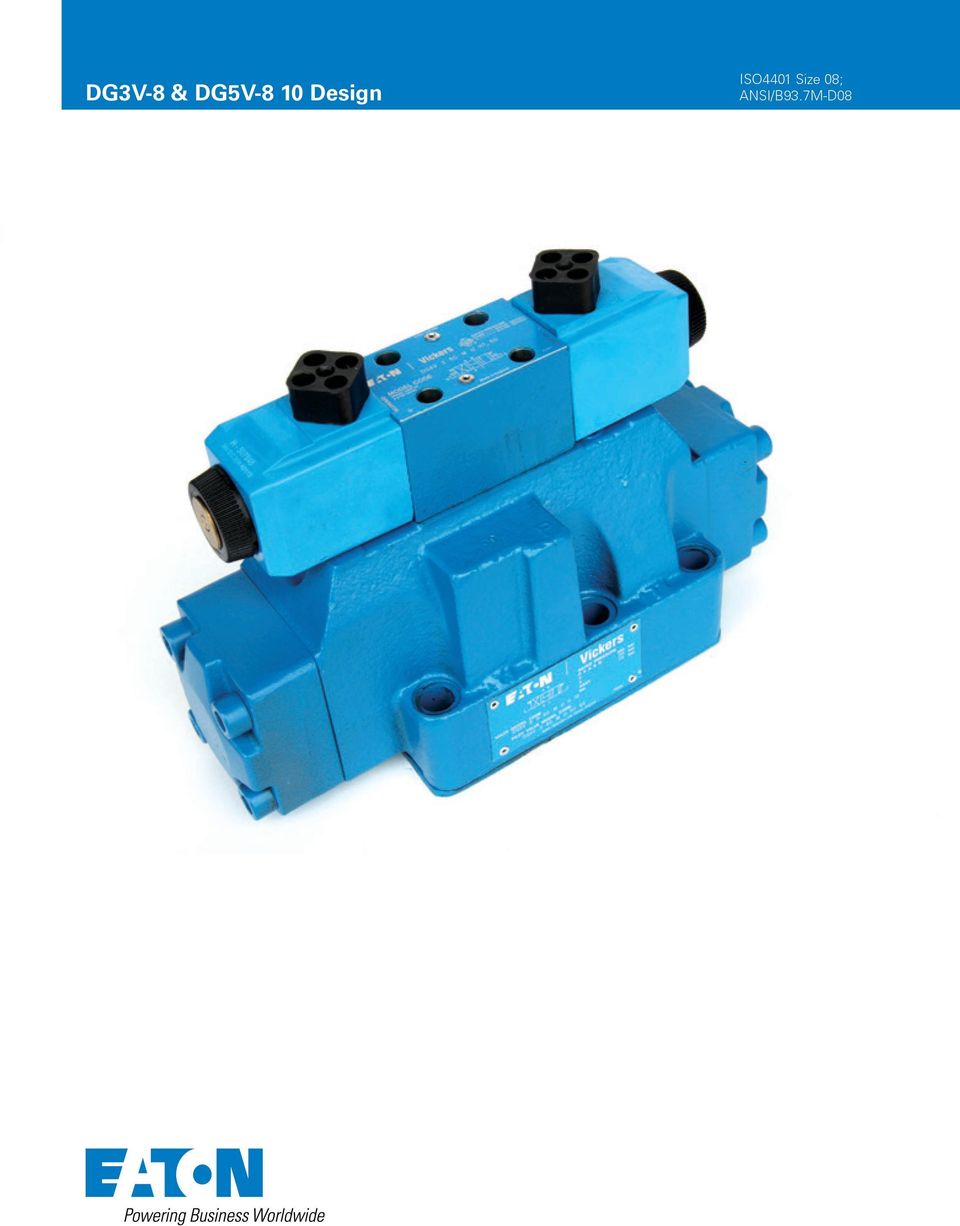
2 Remote Pilot Operated Directional Valve DG3V-8 Design Solenoid Controlled Pilot Operated Directional Valve DG5V-8 Design General description Features and Benefits A mini-system capability with wide variety of spool and spring arrangements, stroke and pilot choke adjustments, integral check valves and port orifices. High force solenoids and centering springs assure consistent shifting through a wide range of pressure and silting extremes. Optional Mainstage Spool Position Monitoring Switch (CE marked) Suitable for demanding industrial or mobile applications by providing for reliable operations. Endurance tested to million cycles and fatigue tested without failure to ensure highest reliability. The Size 8 Directional Control Valve serves as a control valve package. It offers directional control, pilot pressure reducers, pilot chokes, and main stage stroke adjustment to control the flow. The valves are generally used to control large flows up to 7 l/min (85 USgpm) at 35 bar (5 psi) and provide low pressure drops. The range includes: DG3V-8 - remote pilot operated valve. DG5V-8-H - DG4V-3-6 high performance D3 pilot valve bar (3 psi) tank line rating. Each valve contains a mainstage spool which is positioned in the valve by special arrangement. The four arrangements are: Spring offset - For single stage operation, one spring returns spool to an offset position. For two stage operation, springs and washers are removed from main stage and offset action is obtained from pilot valve. Spring centered - Spring and washer are located on both ends of main stage spool to control centering. Pressure centered - Centering springs are used in addition to pilot pressure, to provide positive centering should pilot pressure fail. No spring detented - Springs and washers are provided so that in the event of pilot pressure failure, the main spool will spring center. Fatigue testing performed to NFPA specifications to ensure the highest reliability in applications requiring high flows and pressure. Solid cast body and cored passages for maximum strength and minimal pressure drop. Electrical options including coil types, connections, and wiring housings allow full compatibility and reliable performance in any system application. Plain, waterproof, and lockable manual override options are available to facilitate system troubleshooting or servicing. SECTION THROUGH SPOOL BORE CENTERLINE - EATON DG3V-8 & DG5V-8 Design E-VLVI-SS-E October 5
 Suitable for demanding industrial or mobile applications by providing for reliable operations.")
3 Model Codes DG3V-8 Remote Pilot Operated Directional Valves (F*) - DG3V (B) - ** - (L) - (*) - (*) Special Seals 5 Blank None F3 Seals for fire resistant fluids. F6 Seals for water glycol. Directional Control Valve DG3V Subplate mounting; pilot operatedremote operator. Pressure rating 35 bar (5 psi) for all ports. (See minimum pilot pres sure requirements on page 6. 3 Valve Size 8 Valve size CE TOP 8, NFPA D8 4 Gauge Ports Blank UNF-B Thread B /4 B SP Thread Spool Types Please refer functional symbols on page 7 for spool types. 6 Spool Spring Arrangement Blank No spring A Spring offset to cylinder A C Spring centered D Pressure centered 7 Left Hand Build L A Models only, omit if not required. 8 Spool Control Modifications Blank None Stroke adjustment (both ends ) (available on C & B lank (no spring) models ) Pilot choke adjustment (available on all models ) 3 Pilot choke and stroke adjusters (both ends ) (available on C & B lank (no spring) models ) 7 Stroke adjusters on cylinder A end only (available on A, C & B lank (no spring) models ) 8 Stroke adjusters on cylinder B end only (available on A, C, & B lank (no spring) models ) 7 If both are required (available on A, C, & B lank (no spring) models ) 8 If both are required (available on AL left hand 9 Check Valve in Pressure Port Blank None K,35 bar (5 psi) check Q,4 bar (35 psi) check R 3,45 bar (5 psi) check S 5, bar (75 psi) check Design Number Subject to change. Installation dimensions remain as shown for design numbers through 9. EATON DG3V-8 & DG5V-8 Design E-VLVI-SS-E October 5-3

4 Model Codes DG5V-8 Solenoid Controlled Pilot Operated Directional Valves (F*)-DG5V-8 - * - (B) - * ** - (**) - (*) - P** - (E) - (T) - (*) - (V)M - * ** * * - (L) - (*) - ** Special Seals 7 (Omit if not required.) F3 Seals for fire resistant fluids. F6 Seals for water glycol. Pilot Valve Type H CETOP 3, High performance 3 Gauge Ports Blank UNF-B Thread B /4 BSP Thread 4 Spool Types Please refer functional symbols on page 7 for spool types. 5 Spool spring arrangement A Spring offset, end-to-end (P to B when operated) AL As A but left-hand build (P to A when operated) B Spring offset, endtocenter (P to B when operated) BL As B but left-hand build (P to A when operated) C Spring centered N Two-position detented DG5V option. Same function from DG3V-8-*C valves by alternating pilot supply to one port (X or Y) and permanently draining the other. 6 Manual Override Option Blank Plain override in solenoid end(s) only H Water-resistant manual override on solenoid end(s) W Twist & lock override in solenoid ends Z No override at either end No override in non-solenoid end of single-solenoid valves. Spool Control Blank None Stroke adjustment at both ends Pilot choke adjustment both ends 3 and combined 7 Stroke adjustment, port A end only 8 Stroke adjustment, port B end only 7 and 7 combined 8 and 8 combined Omit if not required Not applicable to DG5V-7-*B(L) models. Not applicable to models shown in the Spring offset, end-to-center, opposite hand section on page 6 Not applicable to models shown in the Spring offset, end-to-center section on page 6 Not applicable for spool 8 models 8 Main Stage Spool Monitoring Switch Blank None PCA Center sensing switch on A port end (not available on D, pressure centered, and /3/7/7, stroke adjust models) PCB Center sensing switch on B port end (not available on /3/8/8, stroke adjust models) PDA Double offset sensing switch on A port end (not available on D, pressure centered, and /3/7/7, stroke adjust models) PDB Double offset sensing switch on B port end (not available on /3/8/8, stroke adjust models) PCD Center sensing switch on A port end and double offset sensing switch on B port end (not available on D, pressure centered, and /3/7/8/7/8, stroke adjust models) PPA Offset sensing proximity switch A port end (not available on D, pressure centered, and /3/7/7, stroke adjust models) PPB Offset sensing proximity switch B port end (not available on /3/8/8, stroke adjust models) PPD Offset sensing proximity switch both ends (not available on D, pressure centered, and /3/7/8/7/8, stroke adjust models) Note: The spool position monitoring switch shown on this technical document is CE marked and certified and complies to European Standard EN 6-6-4: (Emissions) for Class A and European Standard EN 6-6-: (Immunity). 9 External Pilot Pressure E External pilot pressure. Omit for internal pilot pressure models. Internal Pilot Drain T Internal pilot drain to T port. Omit for external pilot drain models. Check Valve in Pressure Port (Omit if not required.) K,35 bar (5 psi) check Q,4 bar (35 psi) check R 3,45 bar (5 psi) check S 5, bar (75 psi) check Solenoid Energization Identity Blank Standard arrangement for ANSI B93.9 (i.e. energize solenoid A to follow flow P to A). V Solenoid identification determined by position of solenoid (i.e. solenoid A at port A end/solenoid B at port B end). Note 4 and 8 type spools are always V. Solenoid energization identity is independent of mainstage porting. 3 Flag Symbol M Electrical options and features 4 Coil Type U ISO44, DIN4365 connector U ISO44 fitted with PG plug U6 ISO44 with fitted DIN plug with lights KU Top exit flying lead (5mm) KUP4 unior timer (Amp) connector KUP5 Integral Deutsch connector FW Flying lead with / NPT thread wiring housing FTW Fly. lead wired terminal block & / NPT thread wiring housing FPA3W Fly. lead, 3 Pin connector & / NPT thread wiring housing FPA5W Fly. lead, 5 pin connector & / NPT thread wiring housing -4 EATON DG3V-8 & DG5V-8 Design E-VLVI-SS-E October 5
 AL As A but left-hand build (P to A when operated) B Spring offset, endtocenter (P to B when operated) BL As B but")
5 Model Codes (Contd.) (F*)-DG5V-8 - * - (B) - * ** - (**) - (*) - P** - (E) - (T) - (*) - (V)M - * ** * * - (L) - (*) - ** Indicator Lights Blank None L Solenoid indicator light Flying lead coil type only 6 Surge Suppressor damper (DC voltages only, omit if not required) D Diode positive bias D Negative bias D7 Transorb type 7 Coil Voltage See electrical information on page 9 for voltages available. Others available upon request. B V AC 5Hz/V AC 6 Hz BL V 5 Hz/V 6 Hz D V AC 5 Hz/4V AC 6 Hz DS 8V DC 3 watt G V DC GL V DC H 4V DC HL 4V DC HM 4V DC 8 watt 8 Design Number EATON DG3V-8 & DG5V-8 Design E-VLVI-SS-E October 5-5

6 Application Notes General Description DG5V-8 models are twostage directional control valves having an integrally mounted wet armature solenoid pilot valve. These valves are generally used to control the movement of a work cylinder or the rotation of a fluid motor. Pressure Centered Models Designated by D under spring/spool arrangement in model code. This option provides faster, more positive spring centering time by use of pilot pressure to center the spool. The valve spool is returned to center position when pilot pres sure is applied at both ends of the spool. The centering springs are used in addition to pilot pressure to ensure positive centering of spool. If pilot pres sure fails or falls below the required minimum, the spool will spring return to the center position. Pilot pres sure is not available through the use of and integral check valve. Pressure centered valves have a drain port W and must have provisions for this feature. Note Pressure centered valves require a pilot valve which directs pilot oil to connections X and Y of the valve at the same time pressure centering is desired. The centering time depends on the rate of pressure rise in the pilot chamber. Spring Offset Models Designated by A under spring/spool arrangement in model code. Spring offset model has an internal spring which returns the spool to offset position when the pilot connection X is open to tank. Pilot connection Y becomes a drain connection and must be pioped directly to tank at atmospheric pressure through a surge-free tank line. Back pressure at this connection would cause valve to malfunction. Caution: Spring offset models contain a high assembled spring load. Call Eaton Service for disassembly instructions. Spring Centered Models Designated by C under spring/spool arrangement in model code. A spring and washer arrangement is used on both ends of the spool. If control pressure is removed, the valve will go to center position due to spring force. No-Spring Models Designated by a Blank under spring/spool arrangement in model code. When the solenoid is deenergized, the spool returns to the last position attained. Performance Characteristics Spring centered, pressure centered and spring offset models require continuous pilot pressure to maintain shifted position. Spring centered models return valve spool to center position by centering springs when pilot pressure fails or falls below minimum requirement. Shift Times Shift times are defined as the time from pilot pressure application/removal to the point of the s tart of a pressure rise/decline in appropriate port. Caution: Flow conditions of the spring centered position must be selected with care, both for the effect on the direction of the flow, and the pilot pres sure. (The 9 main spool will not ensure sufficient pilot pressure in the center position for internal pilot pressure models). Pressure centered models: Valve spool is returned to center position by pilot pressure, when pilot pressure is removed. If pilot pressure fails or falls below the required minimum, the valve spool will spring return to center position. (At spring centered valve flow rates ). Caution: Surges of oil in a common tank line serving these and other valves can be sufficient enough to cause inadvertent shifting of these valves. This is very critical in the no-spring detented valves. Separate tank lines or a vented manifold with a continuous downward path to tank is necessary. Note Any sliding spool valve, if held for long periods of time, may s tick and not spring return due to fluid residue formation and therefore, should be cycled periodically to prevent this from happening. Shifting Action The pilot valve solenoids of spring centered, pressure centered, and spring offset models must be energized continuous ly to keep the main stage spool in the shifted position. No-spring detented models only need to be energized momentarily (for approximately. second). Spring centered and pressure centered models return the valve spool to the center position when both solenoids are de-energized or pilot pres sure fails or falls below minimum requirements. Spring offset models return the spool to the offset position by pilot pres sure when the solenoid is deenergized. When no-spring detented models are de-energized, the pilot and main spools remain in their las t position as long as there are no unusual shock, vibration, or pressure transients, and the spool axis is horizontal. If pilot pressure fails or falls below minimum requirements, the main spool will spring center (at spring centered flow rates ), but will not drift to a reversal of flow position. The pilot stage will remain in the detented position. When used as other than a normal 4 way valve, consult your Eaton representative. -6 EATON DG3V-8 & DG5V-8 Design E-VLVI-SS-E October 5

7 6 3 X Functional Symbols 3 3 Y33 Spool Type and Center Position DG4V-5-*C valves DG4V-5-*B 3 valves DG4V-5-*BL valves 3 DG4V-5-*C 8 valves DG4V-5-*B valves DG4V-5-*BL valves DG4V-5-*C valves DG4V-5-*B valves DG4V-5-*BL valves Spool Types 35 Notes: 3 Shown in 3-position form, plus transients.. In the detailed and simplified symbols on this and the previous 33 b o a pages, the transient positions are omitted for simplicity In certain 3 6-position valves, the o position 6 becomes an additional transient, i.e. 6 in DG5V-8-*A(L) and DG5V-8-*N valves *N valves DG4V-5-*A valves DG4V-5-*AL 8 valves Your Eaton 5 representative can *C valves DG4V-5-*B 5 valves provide DG4V-5-*BL further 5 details. valves Transient condition only Transient 56 condition only. 6 DG3V-8 Pilot Operated Models 7 Comprehensive and simplified symbols DG3V-8 Options 8 Spring Offset, End-to-End, Spring Offset, End-to-End, DG3V-8-*A Opposite Hand, DG3V-8-*AL The following are shown in a DG3V-8-*C example: 3. Pilot choke 3 module. Stroke adjusters at either 3 3 or at both ends (shown at b a b a 3 33 both 33 ends in example) X P T Y B A X P T Y B A One or more options can B A 5 B A be built 5 into any DG3 series X b a b a Y Y X valve. 6 P T 56 P T 56 Spring Centered, DG3V-8-*C b o a Transient condition only. Both ports T A and T B are available. 6 b o a X P T Y B A B A b P Both ports T A and T B are ava Both ports T A and T B are ava Transient condition only. Both ports T A and T B are ava o a T X P T Y B A B A X b o a Y P T EATON DG3V-8 & DG5V-8 Design E-VLVI-SS-E October 5-7
 and 67 7 7 7 DG5V-8-*N valves.")
8 Functional Symbols DG5V-8, Solenoid Controlled, Pilot Operated Models Comprehensive and simplified symbols shown configured for external pilot supply and internal drain Spring Offset, End-to-End, DG5V-8-*A Spring Offset, End-to-End, Opposite Hand, DG5V-8-*AL Spring Centered, DG5V-8-*C b o a b o a b o a X P T Y B A B A X X P T Y B A B A X P T Y B A A B b a b a b o a P T Y P T Y P T Y Spring Offset, End-to-Center DG5V-8-*B Spring Offset, End-to-Center, Opposite Hand DG5V-8-*BL Detented, DG5V-8-*N b o a b o a b o a X P Y B A A B X P T Y B A A B X P T Y B A A B b o o a b a P T Y P T Y P T Y DG5V-8 Options The following are shown in a DG5V-8-*C example:. Pilot choke module. Stroke adjusters, at either or at both ends (shown at both ends in example) 3. External pilot connection 4. Internal drain One or more options can be built into any DG5 series valve. b o a 3 4 X P T Y B A A B b o a X P T -8 EATON DG3V-8 & DG5V-8 Design E-VLVI-SS-E October 5
 3. External pilot connection 4.")
9 Operating Data MAXIMUM PRESSURES: DG3V-8 valves; ports: P, A, B and T * 35 bar (5 psi) Y 35 bar (5 psi) DG5V-8 valves, (externally drained) P, A, B, T and X * 35 bar (5 psi) Y 35 bar (5 psi) DG5V-8 valves, (internally drained) P, A, B and X 35 bar (5 psi) T 35 bar (5 psi) Maximum flow without mal-function (DG3V-8 and DG5V-8) 7 L/min (85 Usgpm) Pilot pressures See Pilot Pressures on page 8 ELECTRICAL INFORMATION: Voltage ratings, DG5V valves See 7 in Model Code on page 5 Voltage limits, DG5V valves: Maximum voltage See Temperature limits, on page Minimum voltage 9% of rated voltage Power consumption, DG5V valves with AC solenoids: Initial VA rms Holding VA rms Dual-frequency coils at 5 Hz, types B and D Dual-frequency coils at 6 Hz, types B and D 6 48 Power consumption, DG5V valves with DC solenoids 3W at rated voltage and C (68 F) Relative duty factor, DG5V valves Continuous; ED = % Type of protection, DG5V valves: ISO 44 coils with plug fitted correctly IEC 44 class IP65 unction box IEC 44 class IP65 (NEMA 4) Coil winding Class H Lead wires (coil types F**** ) Class H Coil encapsulation Class F Note: For information on pilot valves please refer segment B, C, D of the catalog. The DG5V, design two-stage valves have been designed to satisfy the needs of most applications. Consult your Eaton representative about an alternative model if: a) Valves are required to remain pressurized for long periods without frequent switching, and /or b) Back pressure on the drain port of externally drained models (or the tank port of internally drained models) is required to rise above 35 bar (5 psi). * The method for verifying the rated fatigue pressure of the complete unit conforms to NFPA/T.6. R-99 (Catalog C/9), Fluid Power Systems and Products method for verifying the fatigue pressure rating of the pressure containing envelope. Internal drain models drain the pilot valve through the tank port of the mainstage. External drain models drain the pilot valve through the Y port of the mainstage. To provide proper operation without malfunction, the pilot pressure must always exceed tank or drain line pressure by the minimum pilot pressure required per valve and spool type (see charts on page 6). Tank or drain line surges which would reduce this differential are to be avoided as they may cause the mainstage to shift. Mainstage tank pressure is limited to the tank line rating of the pilot valve on internally drained models (with T included in the model code). Internal drains may be used with all models except pressure centered D models. Pressure centered models must be externally drained through Y and W ports. To achieve the maximum tank line rating of 35 bar (5 psi) of the mainstage, an external pilot drain must be used and it is recommended that a separate line be provided directly to the tank. EATON DG3V-8 & DG5V-8 Design E-VLVI-SS-E October 5-9

10 Operating Data Pressure drop characteristics See page, Response times, DG5V valves: Typical values for a DG5V-8-C-E spring centered, externally piloted valve under standard test conditions and operating with 5 L/min (4 USgpm) at 35 bar (5 psi). Coil rating: Pilot pressure, bar (psi): Energizing Time, ms De-energizing V 5 Hz 5 (8) (73) (8) 4 4 (3) (36) 4 4 4V DC 5 (8) (73) (8) (3) (36) From applying a signal at the solenoid until the main-stage spool completes its travel. In pure switched circuit conditions, devoid of the effects of any suppression diodes and full-wave rectifiers. TEMPERATURE LIMITS: Fluid temperature limits See appendix Ambient temperature limits: See appendix Minimum ambient, all valves - C (-4 F) Maximum ambients, DG5V valves with coils listed in in Model Code two pages back, and under conditions stated below: Dual-frequency coils: at 5 Hz and 7% of rated voltage 65 C (5 F) at 5 Hz and % of rated voltage 65 C (5 F) at 6 Hz and 7% of rated voltage 65 C (5 F) at 6 Hz and % of rated voltage 65 C (5 F) Single-frequency (5 Hz) coils at 5 Hz and 65 C (5 F) % of rated voltage DC coils at % of rated voltage 7 C (58 F) INSTALLATION DIMENSIONS: Valves See page 6 to 5 Mass (weight), basic models: kg (lb) approx. DG3V-8-*A(L), (.) DG3V-8-*/*B(L)/*C 7,3 (6.) DG5V-8-*A/B (AC voltages) 8,4 (8.5) DG5V-8-*A/B (DC voltages) 8,5 (8.7) DG5V-8-*C/N (AC voltages) 8,7 (9.) DG5V-8-*C/N (DC voltages) 9, (.) Add, kg (.4 lb) when pilot chock adjustment is fitted. Note: For information on pilot valves please refer segment B, C, D of the catalog. - EATON DG3V-8 & DG5V-8 Design E-VLVI-SS-E October 5

11 Performance Data DG3V 8 Models Typical with mineral oil at 36 cst (68.6 SUS) and a specific gravity of.87. Maximum flow rates Performance based on full power solenoid coils warm and operating at 9% rated voltage. Pressure Drop & Malfunction Flow The following table lists the appropriate pressure drop curve and malfunction flow curve between ports for each spool type. Use the following example to determine pressure drop for a selected spool. Example: Find the pressure drop from P B for type 7 spool. Using the table find numeral 7 in the spool type column. To the right of numeral 7 find the reference curve (from pressure drop curve chart at bottom of page) under P B column. The pressure drop from P B for type 7 spool would be obtained on curve. Likewise, the malfunction for numeral 7 would be found Pressure Drop Curves Spool Pressure Drop Curve Number Malfunction Flow Type P A B T P B A T P T in Center Curve Number bar 4 psid) 89 L/min (5 USgpm) See page on curve (from malfunction flow curve chart at bottom of page).. Figures in the pressure drop chart give approximate pressure drop (ΔP) when passing 473 l/min (5 USgpm) flow (Q) of 35 cst (64 SUS) fluids(s) having.865 specific gravity.. For any other flow rate (Q ), the pressure drop (ΔP ) will be approximately: ΔP = P(Q /Q). 3. For any other viscosity(s), the pressure drop (ΔP), will change as follows: 4. For any other specific gravity (G ), the pressure drop (ΔP ) will be approximately: ΔP = ΔP(G /G). Viscosity cst (SUS) (7.5) (97.8) () (5) (3) (35) (399) % of PΔ (Approx.) Malfunction Flow Curves PRESSURE DROP bar 3, 7,5 4,, 7, 4,, 7, 3,5 FLOW USgpm PRESSURE DROP psi PRESSURE DROP bar FLOW USgpm FLOW L/min PRESSURE DROP psi FLOW L/min EATON DG3V-8 & DG5V-8 Design E-VLVI-SS-E October 5 -

12 Performance Data DG3V-8 Model Response Time The response time shown in the charts are defined as the time between pilot pressurization/ de-pressurization and the initial change in the inlet port pressure. SPRING CENTERING RATED FLOW & PRESSURE Spool Type Closed Center Open Center Time.4 sec..5 sec. Time - msec Offset to Offset Pilot pressure - bar Low shock shift 5 Low shock spring return Fast response shift Fast response spring return 5 3 Pilot pressure - psi Center to Offset Centering Times for Pressure Centered Rated Pressure (A to P or B to P) ee malfunction flow curves on page bar (5 psi) 35 bar (5 psi) 35 bar (5 psi) nforms to NFPA/T.6. R-99 e fatigue pressure rating of the Time - msec Pilot pressure - bar Low shock Fast response Pilot pressure - psi Pressure Drop Across Check Valve Integral Check Valves For internal pilot pressure, an integral pressure port check valve is available. This back pressure will be present at the cylinder ports. The pilot pressure generated is the total of: P T drop through the valve in center condition, pressure drop through the check valve, plus the pressure at the tank port. To prevent load drop, a check valve in the pressure port can be used to prevent reverse flow from a cylinder port to the pressure port. PRESSURE DROP - bar 48,3 4,4 34,5 7,6,7 3,8 6,9 FLOW - USgpm R Spring S Spring Q Spring FLOW - L/min K Spring PRESSURE DROP - psi - EATON DG3V-8 & DG5V-8 Design E-VLVI-SS-E October 5
 ee malfunction flow curves on page 7.")
13 Performance Data DG5V-8 Model Pressure Drop & Malfunction Flow The following table lists the appropriate pressure drop curve and malfunction flow curve between ports for each spool type. Use the following example to determine pressure drop for a selected spool. Example: Find the pressure drop from P B for type 7 spool. Using the table find numeral 7 in the spool type column. To the right of numeral 7 find the reference curve (from pressure drop curve chart at bottom of page) under P B column. The pressure drop from P B for type 7 spool would be obtained on curve. Likewise, the malfunction for numeral 7 would be found on curve (from malfunction flow curve chart at bottom of page).. Figures in the pressure drop chart give approximate pressure drop (ΔP) when passing 473 l/min (5 USgpm) flow (Q) of 35 cst (64 SUS) fluids(s) having.865 specific gravity.. For any other flow rate(q ), the pressure drop (ΔP ) will be approximately ΔP = ΔP(Q /Q). 3. For any other viscosity(s), the pressure drop (ΔP), will change as follows: 4. For any other specific gravity (G ), the pressure drop (ΔP ) will be approximately: ΔP = ΔP(G /G). Viscosity cst (SUS) (75) (5) () (5) (3) (35) (4) % of PΔ (Approx.) SPOOL MALFUNCTION TYPE PRESSURE DROP CURVE NUMBER FLOW CURVE NUMBER P A B T P B A T P T In Center bar (4 psid) 89 L/min (5 USgpm) A See page Pressure Drop Curves Malfunction Flow Curves FLOW USgpm 3, FLOW USgpm , , , PRESSURE DROP bar 7, 4,, 7, 3, FLOW L/min PRESSURE DROP psi PRESSURE DROP bar FLOW L/min PRESSURE DROP psi EATON DG3V-8 & DG5V-8 Design E-VLVI-SS-E October 5-3
.")
14 Performance Data DG5V-8 Model Response Times Response times are defined as the time from solenoid energization/de-energization to the point of the start of a pressure rise/decline in appropriate port. Solenoid Energizing Spring centered, pressure centered and spring offset DG5V-8 types must be energized continuously. No-spring detented DG5V-8 type may be energized momentarily. Pressure centered and spring centered DG5V-8 types return valve spool to center position when both solenoids are de-energized. Mounting Position No spring detented valves must be installed with the longitudinal axis horizontal for good machine reliability. The mounting position of spring centered and spring offset models is unrestricted provided that the pilot pressure supply is maintained as required. (Spring offset valves do not have a spring in the main spool section). Offset to Offset 6 Pilot pressure - bar SPRING CENTERING RATED FLOW & PRESSURE Time - msec Low shock solenoid shift Low shock spring return Fast response solenoid shift Spool Type Closed Center Open Center Time.4 sec..5 sec. 5 Fast response spring return Center to Offset Pilot pressure - psi Pilot pressure - bar Centering Times for Pressure Centered Rated Pressure (A to P or B to P) Pilot pressure - bar Time - msec Low shock Fast response Time - msec Pilot pressure - psi Standard Low Shock Fast Response -4 EATON DG3V-8 & DG5V-8 Design E-VLVI-SS-E October 5

15 Optional Features Integral Check Valves For internal pilot pressure, an integral pressure port check valve is required for internally piloted valves with open center spools (,,4,8 & 9). The pilot pressure generated is the total of: P T drop through the valve in center condition, pressure drop through the check valve, plus the pressure at the tank port. For proper operation, total pressure drop must be greater than the minimum required pilot pressure (see chart). To prevent load drop, a check valve in the pressure port can be used to prevent reverse flow from a cylinder port to pressure port. If using as reverse flow check, maximum reverse pressure is limited to bar (3 psi). Pressure Drop Across Check Valve PRESSURE DROP - bar 48,3 4,4 34,5 7,6,7 3,8 6, R Spring S Spring FLOW - USgpm Q Spring FLOW - L/min K Spring PRESSURE DROP - psi EATON DG3V-8 & DG5V-8 Design E-VLVI-SS-E October 5-5

16 Installation Dimensions DG3V-8-(C)-*-*- Spring Centered Model Millimeters (inches) Tank Port Ø 5, (.98) 53, (.9) 3, (5.3) Pressure Port Ø 5, (.98) Std. Model Ø 7,3 (.7) P-Port Check Model Pilot Pressure Port Y 35,4 (.39) 9, (3.63) 46, (.8) 7,8 (.79) Pilot Pressure Port X A D 8,9 (3.9) Port A Ø 5, (.98) 8, (3.9) 77, (3.3) 53, (6.) 64,9 (6.49) 75, (.95) Mounting bolt holes Ø3,5 (.53) 6 places Port B Ø 5, (.98) See pilot choke adjustment installation for additional dimensions not shown. Gauge ports UNF-B thread for.5 O.D. tubing or / 4 BSP thread, (4.37) 35,5 (.4) 8,5 (4.67) 46, (.8) 4, (.6) 53, (.9) C,7 (3.96) B 87,3 (7.38) 3, (.) 4,5 (.67) 58,5 (.3) Dimension to mounting bolt counterbore hole 6-places Ø 6,4 (.5) Orientation Pin -places 6,5 (.5) SPOOL CONTROL MODIFICATIONS A B C D DIMENSION (PILOT DIMENSION DIMENSION DIMENSION CHOKE ADUSTMENT) Without pilot choke or stroke adjustment 33, (5.3) 65,3 (.44) 3,6 (5.) Stroke adjustment (both ends) 33, (5.3) 45,9 (6.37) 8, (8.8) Pilot choke adjustment 73, (6.8) 65,3 (.44) 3,6 (5.) 34, (5.8) Stroke adjustment on cyl. A 33, (5.3) 34,6 (3.4) 8, (8.8) Stroke adjustment on cyl. B 33, (5.3) 34,6 (3.4) 3,6 (5.) Pilot choke and stroke adjustment on cyl. A 73, (6.8) 34,6 (3.4) 8, (8.8) 34, (5.8) Pilot choke and stroke adjustment on cyl. B 73, (6.8) 3,6 (5.) 34, (5.8) 34, (5.8) Pilot choke and stroke adjustment (both ends) 73, (6.8) 45,9 (6.37) 8, (8.8) 34, (5.8) -6 EATON DG3V-8 & DG5V-8 Design E-VLVI-SS-E October 5
 35,5 (.4) 8,5 (4.67) 46, (.8) 4, (.6) 53, (.9) C,7 (3.96) B 87,3 (7.38) 3, (.) 4,5 (.67) 58,5 (.3) Dimension to mounting bolt counterbore hole 6-places Ø 6,4 (.")
17 Installation Dimensions DG3V-8-(L)-*-*- Spring Offset Model Millimeters (inches) A D 83,4 (3.8) C B 94,4 (7.65) SPOOL CONTROL MODIFICATIONS A B C D DIMENSION (PILOT DIMENSION DIMENSION DIMENSION CHOKE ADUSTMENT) Without pilot choke or stroke adjustment 33, (5.3) 65,3 (.44) 3,6 (5.) Without pilot choke or stroke adjustment 33, (5.3) 36,9 (.87) 94,4 (7.65) 34, (5.8) (left-hand build) Pilot choke adjustment 73, (6.8) 65,3 (.44) 3,6 (5.) 34, (5.8) Stroke adjustment on cyl. A (left-hand build) 33, (5.3) 4,3 (5,83) 8, (8.8) Stroke adjustment on cyl. B 33, (5.3) 34,6 (3.4) 3,6 (5.) Pilot choke and stroke adjustment on cyl. A 73, (6.8) 34,6 (3.4) 8, (8.8) 34, (5.8) (left-hand build) Pilot choke and stroke adjustment on cyl. B 73, (6.8) 34,6 (3.4) 3,6 (5.) 34, (5.8) DG3V-8-D-*-*- Pressure Centered Model Millimeters (inches) A 84,9 (3.34) D 93,5 (7.6) B EATON DG3V-8 & DG5V-8 Design E-VLVI-SS-E October 5-7
 33, (5.3) 4,3 (5,83) 8, (8.8) Stroke adjustment on cyl. B 33, (5.3) 34,6 (3.4) 3,6 (5.) Pilot choke and stroke adjustment on cyl. A 73, (6.8) 34,6 (3.4) 8, (8.8) 34, (5.")
18 Installation Dimensions Pilot Choke DGMFN-3-Y-AW-BW-4 Pilot choke increases the amount of time to shift the mainstage spool, lowering the possibility of large flow transients in the circuit. It is adjusted by backing off locknuts and turning adjusting screws inward to decrease rate of spool travel and outward to increase spool travel rate. See spool control modifications in model code. Pilot Choke Stroke Adjustment Stroke Adjustment Stroke adjustment limits movement of the mainstage spool. Backing off the jamnut and turning the adjusting screw inward decreases spool stroke. See spool control modifications in model code.). -8 EATON DG3V-8 & DG5V-8 Design E-VLVI-SS-E October 5

19 Installation Dimensions DG5V-8 H-*-M-*- Spring Centered Model Millimeters (inches) 9, (3.63) 46, (.8) Tank Port Ø 5, (.98) 3, (5.3) 53, (.9) Pressure Port Ø 5, (.98) Std. Model Ø 7,3 (.7) P-port Check Model Pilot Drain Port Y (For External Pilot Drain Models) 35,4 (.39) 7,8 (.79) Pilot Pressure Port X (For External Pilot Pressure Models) Port A Ø 5, (.98) D 77, (3.3) 53, (6.) E Port B Ø 5, (.98) 35,6 (.4) 8,5 (4.67) 46, (.8) A 8,9 (3.9) 4, (.6) 8, (3.9) C 53, (.9),7 (3.96) 87,3 (7.38) B Gauge ports UNF-B thread.5 O.D. tubing or / 4 BSP Thread 3, (.), (4.37) 4,5 (.67) 58,5 (.3) 6, (.) F Dimensions A B C D E pilot F Spool Control Dual Solenoid Single Solenoid Pilot Modifications AC Sol. DC Sol. AC Sol. DC Sol. AC Sol. DC Sol. Choke Without pilot choke or stroke 65,3 3,6 adjustment 35,6 (.44) (5.) Stroke adjustment (5.33) 45,9 8, - (both ends) (6.37) (8.8) Pilot choke adjustment 75,6 65,3 3,6 34, (6.9) (.44) (5.) (5.8) Stroke adjust. on cyl. A 8, 35,6 (8.8) 98,8 8,8,, 46,5 56,5 Stroke adjust on cyl. B (5.33) 3,6 (3.88) (4.8) (7.87) (8.66) (5.76) (6.6) - 34,6 (5.) Pilot choke and stroke (3.4) 8, adjust. on cyl A (8.8) Pilot choke and stroke 75,6 3,6 34, adjust. on cyl. B (6.9) (5.) (5.8) Pilot choke and stroke 45,9 8, adjust. on both ends (6.37) (8.8) EATON DG3V-8 & DG5V-8 Design E-VLVI-SS-E October 5-9
 58,5 (.3) 6, (.) F Dimensions A B C D E pilot F Spool Control Dual Solenoid Single Solenoid Pilot Modifications AC Sol. DC Sol. AC Sol. DC Sol. AC Sol. DC Sol. Choke Without pilot choke or stroke 65,3 3,6 adjustment 35,6 (.")
20 Installation Dimensions DG5V-8-A(L)-*-*- Spring Offset Model Millimeters (inches) D E,9 (4.84) A 83,4 (3.8) F G C B 94,4 (7.65) Dimensions A B C D E pilot F G Spool Control Dual Solenoid Single Solenoid Reducer Pilot Modifications AC Sol. DC Sol. AC Sol. DC Sol. AC Sol. DC Sol. Module Choke Without pilot choke or stroke adjustment 65,3 3,6 75,6 (.44) (5.) Stroke adjustment (6.9) 45,9 8, - (both ends) (6.37) (8.8) Pilot choke adjustment 5,6 65,3 3,6 34, (8.48) (.44) (5.) (5.8) Stroke adjust. on cyl. A 8, 75,6 (8.8) 98,8 8,8,, 46,5 56,5 34, Stroke adjust on cyl. B (6.9) 3,6 (3.88) (4.8) (7.87) (8.66) (5.76) (6.6) (5.8) - 34,6 (5.) Pilot choke and stroke (3.4) 8, adjust. on cyl A (8.8) Pilot choke and stroke 5,6 3,6 34, adjust. on cyl. B (8.48) (5.) (5.8) Pilot choke and stroke 45,9 8, adjust. on both ends (6.37) (8.8) - EATON DG3V-8 & DG5V-8 Design E-VLVI-SS-E October 5
 98,8 8,8,, 46,5 56,5 34, Stroke adjust on cyl. B (6.9) 3,6 (3.88) (4.8) (7.87) (8.66) (5.76) (6.6) (5.8) - 34,6 (5.) Pilot choke and stroke (3.4) 8, adjust. on cyl A (8.")
21 Installation Dimensions DG5V-8-D-*-*- Pressure Centered Model Millimeters (inches) D E A F G 84,9 (3.34) C B Dimensions Spool Control A B C D E pilot F G Modifications Dual Solenoid Single Solenoid Reducer Pilot (without Reducer) AC Sol. DC Sol. AC Sol. DC Sol. AC Sol. DC Sol. Module Choke Without pilot choke or 36, stroke adjustment 35,6 (.83) (5 33) 93,5 98,8 8,8,, 46,5 56,5 _ Stroke adjust on cyl. B (7.6) (3.88) (4.8) (7.87) (8.66) (5.76) (6.6) _ 4 5 Pilot choke and stroke 75,6 (5.8) 34, adjust. on cyl. B (6.9) (5.8) (With reducer) Without pilot choke or 36, stroke adjustment 75,6 (.83) (6.9) _ Stroke adjust on cyl. B 93,5 98,8 8,8,, 46,5 56,5 3, 4,5 (7.6) (3.88) (4.8) (7.87) (8.66) (5.76) (6.6) (5.5) Pilot choke and stroke 5,6 (5.8) adjust. on cyl. B (8.48) 34, (5.8) EATON DG3V-8 & DG5V-8 Design E-VLVI-SS-E October 5 -
22 Optional Features Pilot Choke DGMFN-3-Y-AW-BW-4 Pilot choke increases the amount of time to shift the mainstage spool, lowering the possibility of large flow transients in the circuit. It is adjusted by backing off locknuts and turning adjusting screws inward to decrease rate of spool travel and outward to increase spool travel rate. See spool control modifications in model code. Stroke Adjustment Stroke adjustment limits movement of the mainstage spool. Backing off the jamnut and turning the adjusting screw inward decreases spool stroke. See spool control modifications in model code. Pilot Choke Stroke Adjustment - EATON DG3V-8 & DG5V-8 Design E-VLVI-SS-E October 5
23 Installation Dimensions DG5V-8 with Main Stage Spool Monitoring Switch PC* or PD* Models (LVDT Style Switch) Millimeters (inches) M Thread Connection "A" A Port Side B Port Side " F " " G" MODEL A F G CODE DIMENSION DIMENSION DIMENSION DG5V-8-H-(B)-*A/B/C/F/N(L)-(*)-PCA/PDA-(*)-(V)M-*- 35.6[5.34] 38.7[9.4] 37.3[4.6] DG5V-8-H-R-(B)-*A/B/C/F/N(L)-(*)-PCA/PDA-(*)-(V)M-*- 75.6[6.9] 38.7[9.4] 37.3[4.6] DG5V-8-H-(B)-*A/B/C/F/N(L)-(*)--PCA/PDA-(*)-(V)M-*- 75.6[6.9] 38.7[9.4] 37.3[4.6] DG5V-8-H-R-(B)-*A/B/C/F/N(L)-(*)--PCA/PDA-(*)-(V)M-*- 5.6[8.49] 38.7[9.4] 37.3[4.6] DG5V-8-H-(B)-*A/B/C/F/N(L)-(*)-8-PCA/PDA-(*)-(V)M-*- 35.6[5.34] 38.7[9.4] 446.6[7.58] DG5V-8-H-R-(B)-*A/B/C/F/N(L)-(*)-8-PCA/PDA-(*)-(V)M-*- 75.6[6.9] 38.7[9.4] 446.6[7.58] DG5V-8-H-(B)-*A/B/C/F/N(L)-(*)-8-PCA/PDA-(*)-(V)M-*- 75.6[6.9] 38.7[9.4] 446.6[7.58] DG5V-8-H-R-(B)-*A/B/C/F/N(L)-(*)-8-PCA/PDA-(*)-(V)M-*- 5.6[8.49] 38.7[9.4] 446.6[7.58] DG5V-8-H-(B)-*A/B/C/F/N(L)-(*)-PCB/PDB-(*)-(V)M-*- 35.6[5.34] 3.7[5.] 37.3[4.6] DG5V-8-H-R-(B)-*A/B/C/F/N(L)-(*)-PCB/PDB-(*)-(V)M-*- 75.6[6.9] 3.7[5.] 37.3[4.6] DG5V-8-H-(B)-*A/B/C/F/N(L)-(*)--PCB/PDB-(*)-(V)M-*- 75.6[6.9] 3.7[5.] 37.3[4.6] DG5V-8-H-R-(B)-*A/B/C/F/N(L)-(*)--PCB/PDB-(*)-(V)M-*- 5.6[8.49] 3.7[5.] 37.3[4.6] DG5V-8-H-(B)-*A/B/C/F/N(L)-(*)-7-PCB/PDB-(*)-(V)M-*- 35.6[5.34] 8.[8.9] 446.6[7.58] DG5V-8-H-R-(B)-*A/B/C/F/N(L)-(*)-7-PCB/PDB-(*)-(V)M-*- 75.6[6.9] 8.[8.9] 446.6[7.58] DG5V-8-H-(B)-*A/B/C/F/N(L)-(*)-7-PCB/PDB-(*)-(V)M-*- 75.6[6.9] 8.[8.9] 446.6[7.58] DG5V-8-H-R-(B)-*A/B/C/F/N(L)-(*)-7-PCB/PDB-(*)-(V)M-*- 5.6[8.49] 8.[8.9] 446.6[7.58] DG5V-8-H-(B)-*A/B/C/F/N(L)-(*)-PCD-(*)-(V)M-*- 35.6[5.34] 38.7[9.4] 477.3[8.79] DG5V-8-H-R-(B)-*A/B/C/F/N(L)-(*)-PCD-(*)-(V)M-*- 75.6[6.9] 38.7[9.4] 477.3[8.79] DG5V-8-H-(B)-*A/B/C/F/N(L)-(*)--PCD-(*)-(V)M-*- 75.6[6.9] 38.7[9.4] 477.3[8.79] DG5V-8-H-R-(B)-*A/B/C/F/N(L)-(*)--PCD-(*)-(V)M-*- 5.6[8.49] 38.7[9.4] 477.3[8.79] DG5V-8-H-(B)-*D-(*)-PCB/PDB-(*)-(V)M-*- 35.6[5.34] 93.5[7.6] 43.[7.] DG5V-8-H-R-(B)-*D-(*)-PCB/PDB-(*)-(V)M-*- 75.6[6.9] 93.5[7.6] 43.[7.] DG5V-8-H-(B)-*D-(*)--PCB/PDB-(*)-(V)M-*- 75.6[6.9] 93.5[7.6] 43.[7.] DG5V-8-H-R-(B)-*D-(*)--PCB/PDB-(*)-(V)M-*- 5.6[8.49] 93.5[7.6] 43.[7.] EATON DG3V-8 & DG5V-8 Design E-VLVI-SS-E October 5-3
24 Installation Dimensions DG5V-8 with Main Stage Spool Monitoring Switch PPA, PPB or PPD Models (Proximity Switch) Millimeters (inches) A Port Side M Thread Connection B Port Side "A" " F " " G " MODEL A F G CODE DIMENSION DIMENSION DIMENSION DG5V-8-H-(B)-*A/B/C/F/N(L)-(*)-PPA-(*)-(V)M-*- 35.6[5.34] 86.[7.33] 38.8[.55] DG5V-8-H-R-(B)-*A/B/C/F/N(L)-(*)-PPA-(*)-(V)M-*- 75.6[6.9] 86.[7.33] 38.8[.55] DG5V-8-H-(B)-*A/B/C/F/N(L)-(*)--PPA-(*)-(V)M-*- 75.6[6.9] 86.[7.33] 38.8[.55] DG5V-8-H-R-(B)-*A/B/C/F/N(L)-(*)--PPA-(*)-(V)M-*- 5.6[8.49] 86.[7.33] 38.8[.55] DG5V-8-H-(B)-*A/B/C/F/N(L)-(*)-8-PPA-(*)-(V)M-*- 35.6[5.34] 86.[7.33] 394.[5.5] DG5V-8-H-R-(B)-*A/B/C/F/N(L)-(*)-8-PPA-(*)-(V)M-*- 75.6[6.9] 86.[7.33] 394.[5.5] DG5V-8-H-(B)-*A/B/C/F/N(L)-(*)-8-PPA-(*)-(V)M-*- 75.6[6.9] 86.[7.33] 394.[5.5] DG5V-8-H-R-(B)-*A/B/C/F/N(L)-(*)-8-PPA-(*)-(V)M-*- 5.6[8.49] 86.[7.33] 394.[5.5] DG5V-8-H-(B)-*A/B/C/F/N(L)-(*)-PPB-(*)-(V)M-*- 35.6[5.34] 3.7[5.] 38.8[.55] DG5V-8-H-R-(B)-*A/B/C/F/N(L)-(*)-PPB-(*)-(V)M-*- 75.6[6.9] 3.7[5.] 38.8[.55] DG5V-8-H-(B)-*A/B/C/F/N(L)-(*)--PPB-(*)-(V)M-*- 75.6[6.9] 3.7[5.] 38.8[.55] DG5V-8-H-R-(B)-*A/B/C/F/N(L)-(*)--PPB-(*)-(V)M-*- 5.6[8.49] 3.7[5.] 38.8[.55] DG5V-8-H-(B)-*A/B/C/F/N(L)-(*)-7-PPB-(*)-(V)M-*- 35.6[5.34] 8.[8.9] 394.[5.5] DG5V-8-H-R-(B)-*A/B/C/F/N(L)-(*)-7-PPB-(*)-(V)M-*- 75.6[6.9] 8.[8.9] 394.[5.5] DG5V-8-H-(B)-*A/B/C/F/N(L)-(*)-7-PPB-(*)-(V)M-*- 75.6[6.9] 8.[8.9] 394.[5.5] DG5V-8-H-R-(B)-*A/B/C/F/N(L)-(*)-7-PPB-(*)-(V)M-*- 5.6[8.49] 8.[8.9] 394.[5.5] DG5V-8-H-(B)-*A/B/C/F/N(L)-(*)-PPD-(*)-(V)M-*- 35.6[5.34] 86.[7.33] 37.4[4.66] DG5V-8-H-R-(B)-*A/B/C/F/N(L)-(*)-PPD-(*)-(V)M-*- 75.6[6.9] 86.[7.33] 37.4[4.66] DG5V-8-H-(B)-*A/B/C/F/N(L)-(*)--PPD-(*)-(V)M-*- 75.6[6.9] 86.[7.33] 37.4[4.66] DG5V-8-H-R-(B)-*A/B/C/F/N(L)-(*)--PPD-(*)-(V)M-*- 5.6[8.49] 86.[7.33] 37.4[4.66] DG5V-8-H-(B)-*D-(*)-PPB-(*)-(V)M-*- 35.6[5.34] 93.5[7.6] 379.7[4.95] DG5V-8-H-R-(B)-*D-(*)-PPB-(*)-(V)M-*- 75.6[6.9] 93.5[7.6] 379.7[4.95] DG5V-8-H-(B)-*D-(*)--PPB-(*)-(V)M-*- 75.6[6.9] 93.5[7.6] 379.7[4.95] DG5V-8-H-R-(B)-*D-(*)--PPB-(*)-(V)M-*- 5.6[8.49] 93.5[7.6] 379.7[4.95] -4 EATON DG3V-8 & DG5V-8 Design E-VLVI-SS-E October 5
25 Installation Dimensions Valve for Safety Circuit Application (35A Spool) Main Stage Hydraulic Symbol A B P T A B C D DG5V with PPA Switch Option Shown MODEL A B C D LEAKAGE P-A FLOW CURVE mm (in) mm (in) mm (in) mm (in) cc/min (in 3 /min) DG5V5-35A 8.5 (4.67) 34.7 (9.4) 6. (.3) Available upon request Available upon request DG5V7-35A 5. (5.99) 5. (9.9) 86.6 (.8) Available upon request See DG5V7 catalog DG5V8-35A 5.7 (5.97) 346. (3.6) 38.5 (4.98) 56 (9.5) Available upon request DG5V-35A 3.7 (9.) (7.46) (8.8) Available upon request Available upon request EATON DG3V-8 & DG5V-8 Design E-VLVI-SS-E October 5-5
26 Electrical Information DG5V-8 with Main Stage Spool Monitoring Switch PC* or PD* Models (LVDT Style Switch) Millimeters (inches) SPECIFICATIONS Supply Voltage (Vs) 4VDC ± % (Full Wave Bridge with Capacitor) Reverse Polarity Protection MAX. 3V Installed Ripple Voltage % Current Consumption 4mA Approx. Outputs NC Contact Positive (No Short Circuite Protection) Sensing Distance (offset position) 5.85 to 6.5 mm Sensing Distance (from center position) ±.35 to.65 mm Hysteresis.6 mm Output Voltage Signal <.8V Signal Vs.5V Output Current <4mA at Input +% Environmental Protection IP65 (With Mounted Plug) Operating Temperature Range - C to +85 C Max. Operating Pressure 35 bar (45 psi) CE Declaration of Conformity No P-Channel, Contact Positive ATTENTION: EMC ONLY ENSURED WHEN USING SCREENED CABLES AND SCREENED PLUG CASING. TYPICAL PCA/PCB OUTPUT (FOR SENSING CENTER POSITION) TYPICAL PDA/PDB OUTPUT (FOR FULL SHIFT SENSING) TYPICAL PCD OUTPUT (FOR CENTER SENSING 'A' PORT END, FULL SHIFT SENSING 'B' PORT END) Signal Signal Signal Signal Signal Signal Signal Signal Signal Full Stroke Switch Point (Full Shift Sensing) Switch Point (Center Sensing) Center Switch Point (Center Sensing) Switch Point (Full Shift Sensing) Full Stroke Full Stroke Switch Point Center Switch Point Full Stroke Full Stroke Switch Point Center Switch Point Full Stroke Signal = Voltage at pin /4 <.8V Signal = Voltage at pin /4 > (Vs.5V) Signal = Voltage at pin /4 <.8V Signal = Voltage at pin /4 > (Vs.5V) Signal = Voltage at pin /4 <.8V Signal = Voltage at pin /4 > (Vs.5V) Electrical Schematic and Mating Connector Detail Connector Detail = stab = = OSZILATOR DEMO- DULATOR = = OVERLOAD PROTECTED OUTPUT Input Output Output Ground 4 3 4V ±% R L = R L PIN #4 Output Voltage (Vs -.5V) PIN # Input Voltage (Vs) +4VDC±% PIN #3 Ground PIN # Output Voltage Signal (Vs -.5V) R,R = e.g. Coil Resistance of the switch relay >/ = 6 OHMS L L -6 EATON DG3V-8 & DG5V-8 Design E-VLVI-SS-E October 5
27 Electrical Information DG5V-8 with Main Stage Spool Monitoring Switch PPA, PPB or PPD Models (Proximity Switch) Millimeters (inches) SPECIFICATIONS Supply Voltage (Vs): to 3 Vdc Supply Current (ls): 8mA at 4Vdc (Plug Load Current) Supply Over-Voltage Rating: 35Vdc Continuous Supply Reverse Polarity Rating: -35Vdc (With No Shorts) Short Circuit Tolerance: Continuous Short Between any Two Pins High Potential Test, Pin to Case: 3Vdc Electromagnetic Compatibility: ISO 7637 Parts and Worst Case and Immunity to Radiated Electromagnetic Fields, KHz to GHz per SAE 3/5 SEP 95 Pins to Case Resistance: > 5 MEGOHMS Load Dump Tolerance: 8Vdc PEAK, 4ms Decay, with.5 OHM Source Impedance Switching Frequency: to 3K Hz Output: Open Collector PNP Sourcing, Normally Open Sensing Distance (offset position):.7 ±.5 mm (.5" ±.") of Full Stroke Hysteresis:.5 mm (.") Max. Rise/Fall Time: 6.5/.5 Microsec Rl = 8 OHM, Cl = 8Vdc Output Leakage Current: ma Max Output Voltage High: +Vs.Vdc Min Output Load Current: ma Max Operating Pressure: 35 bar (5 psi) Operating Temperature: -4 to C Humidity: % to % ATTENTION: EMC ONLY ENSURED WHEN USING SCREENED CABLES AND SCREENED PLUG CASING. Signal TYPICAL PPA OUTPUT TYPICAL PPB OUTPUT Signal Signal TYPICAL PPD OUTPUT Signal Output Circuit Wiring Instuctions PIN POWER SUPPLY Signal Switch Point Full Stroke Center Center Full Stroke Switch Point Signal Signal Switch Point Full Stroke Center Full Stroke Switch Point Signal SENSOR K PIN 4 PIN 3 SIGNAL OUTPUT GROUND Signal = Voltage at pin 4 = V Signal = Voltage at pin 4 > (Vs.V) Signal = Voltage at pin 4 = V Signal = Voltage at pin 4 > (Vs.V) Connector Detail PIN #4 Output Voltage Signal (Vs -.V) PIN # Input Voltage (Vs) to 3VDC PIN #3 Ground PIN # Not Used EATON DG3V-8 & DG5V-8 Design E-VLVI-SS-E October 5-7
28 Pilot Valves General description Pilot valves are identified in the model code by the following letters: S Standard or H High Performance. The pilot valves can be ordered to match a variety of mainstage spool types and valve bodies. The chart below shows ordering information for each pilot valve. For example, to order a High Performance pilot H with a Spring Offset mainstage A, use the following model code: DG4V-3- A-M-*-6 MINIMUM PILOT PRESSURE REQUIREMENTS Spool Type Pilot Pressure bar (psi) A, B, C, F, N Models D Models Closed center (5) P to A: (75) P to B: (3) Open center 5 (75) P to A: (5) P to B: (5) VALVE MODEL CODE: HIGH PERFORMANCE/STANDARD MAIN STAGE SPOOL TYPE PILOT VALVE MODEL CODE DG5V-8-H-*A-*-M-*- All except 4 & 8 DG4V-3-A-M-*-6 4A & 8A only DG4V-3-AL-VM-*-6 4AL & 8AL only DG4V-3-A-VM-*-6 DG5V-8-H-*B-*-M-*- All except 4 & 8 DG4V-3-6B-M-*-6 4B & 8B only DG4V-3-6BL-VM-*-6 4BL & 8BL only DG4V-3-6B-VM-*-6 DG5V-8-H-*C-*-M-*- All except 4 & 8 DG4V-3-6C-M-*-6 4C & 8C only DG4V-3-6C-VM-*-6 DG5V-8-H-*D-*-M-*- All except 4 & 8 DG4V-3-7C-M-*-6 4D & 8D only DG4V-3-7C-VM-*-6 DG5V-8-H-*F-*-M-*- All except 4 & 8 DG4V-3-6F-M-*-6 4F & 8F only DG4V-3-6FL-VM-*-6 4FL & 8FL only DG4V-3-6F-VM-*-6 DG5V-8-H-*N-*-M-*- All except 4 & 8 DG4V-3-6N-M-*-6 4N & 8N only DG4V-3-6N-VM-*-6-8 EATON DG3V-8 & DG5V-8 Design E-VLVI-SS-E October 5
29 Notes EATON DG3V-8 & DG5V-8 Design E-VLVI-SS-E October 5-9
30 Eaton Hydraulics Group USA 465 Lone Oak Road Eden Prairie, MN USA Tel: Fax: Eaton Hydraulics Group Europe Route de la Longeraie 7 Morges Switzerland Tel: +4 () 8 46 Fax: +4 () 8 46 Eaton Hydraulics Group Asia Pacific Eaton Building 4th Floor, No.7 Lane8 Linhong Rd. Changning District Shanghai 335 China Tel: (+86 ) 5 99 Fax: (+86 ) Eaton All Rights Reserved Printed in USA Document No.: E-VLVI-SS-E October 5
E4E PILOT OPERATED DIRECTIONAL CONTROL VALVE WITH ELECTRIC PROPORTIONAL CONTROL SERIES 51
 83 300/100 ED E4E PILOT OPERATED DIRECTIONAL CONTROL VALVE WITH ELECTRIC PROPORTIONAL CONTROL SUBPLATE MOUNTING CETOP P05 p max 250 bar Q max (see specification table) MOUNTING INTERFACE OPERATING PRINCIPLE
Check Valves. Pilot Operated Check Valves. Vickers. PCGV-6/8, 10 Series; PCG5V-6/8, 20 Series. Typical Section. Features and Benefits
 Vickers Check Valves Pilot Operated Check Valves PCGV-6/8, 10 Series; PCG5V-6/8, 20 Series Typical Section Typical PCG5V model with internally drained pilot piston internal leakage through the closed pilot
Pressure Relief. Pressure Relief and Sequence Valves CG2V-6/8, 10 Series; CG5V-6/8, 20 Series. Vickers. Features and Benefits.
 Vickers Pressure Relief Pressure Relief and Sequence Valves CG2V-6/8, 1 Series; CG5V-6/8, 2 Series Typical Section CG2V-6*W-1 relief valve Basic Characteristics Maximum pressure.......... 35 bar (5 psi)
Directional Controls
 Vickers Directional Controls DG5S-8 and DG5S-H8 wo-stage, Solenoid Controlled, ilot Operated, Four-Way Directional Valves Revised 11/94 591 Introduction General Description he DG5S-8 and DG5S-H8 are two-stage
DXPE*J 85 320/215 ED. DIRECtIONAL CONtROL VALVE PILOt OPERAtED, WItH OBE AND FEEDBACK. Q max (see performance table) SERIES 30
 SERIES 30") 85 320/215 ED DXPE*J DIRECtIONAL CONtROL VALVE PILOt OPERAtED, WItH OBE AND FEEDBACK SUBPLAtE MOUNtINg DXPE5J CEtOP P05 DXPE5RJ ISO 4401-05 (CETOP R05) DXPE7J ISO 4401-07 (CETOP 07) DXPE8J ISO 4401-08
85 320/215 ED DXPE*J DIRECtIONAL CONtROL VALVE PILOt OPERAtED, WItH OBE AND FEEDBACK SUBPLAtE MOUNtINg DXPE5J CEtOP P05 DXPE5RJ ISO 4401-05 (CETOP R05) DXPE7J ISO 4401-07 (CETOP 07) DXPE8J ISO 4401-08
Cartridge Valves. Solenoid Valves. Vickers. Screw-in Cartridge Valves. Maximum Pressure 210 bar (3000 psi) Maximum Flow 227 l/min (60 USgpm)
 Maximum Flow 227 l/min (60 USgpm)") Vickers Cartridge Valves Solenoid Valves Screw-in Cartridge Valves Maximum Pressure bar ( psi) Maximum Flow 7 l/min (6 USgpm) Rev /99 77 Introduction For over seventy years, Vickers has provided its customers
Vickers Cartridge Valves Solenoid Valves Screw-in Cartridge Valves Maximum Pressure bar ( psi) Maximum Flow 7 l/min (6 USgpm) Rev /99 77 Introduction For over seventy years, Vickers has provided its customers
Fluid. Flu. Fluid Fluid. uid Power d Power P. Fluid Power P. Fluid Power. Fluid Power Power. d Power. Directional Cetop Valves DCV 03.
 Catalogue Directional Cetop Valves DCV 03 Power Flu uid Power d Power P wer Power Power Power Power Power d Power Power Power ower Power Power wer Power Power P Power Power Powe d Power Power Power Power
RPE3-04. Functional Description HA 4014 10/2010. Directional Control Valves Solenoid Operated. Replaces HA 4014 12/2007
 Directional Control Valves Solenoid Operated RPE3-04 Size D 04 (02) 320 bar (4600 PSI) 30 L/min(8.0 GPM) HA 4014 10/2010 Replaces HA 4014 12/2007 4/3-, 4/2- way directional control valves with solenoid
Pressure Relief. Pressure Control Valve R(C)G(O)-03, 06 and 10; R(C)T(O)-03, 06 and 10 VICKERS. Basic Characteristics. Sectional Illustrations
G(O)-03, 06 and 10; R(C)T(O)-03, 06 and 10 VICKERS. Basic Characteristics. Sectional Illustrations") VICKERS Pressure Relief Pressure Control Valve R(C)G(O)-03, 06 and 10; R(C)T(O)-03, 06 and 10 Sectional Illustrations RCG-** Model Shown RCT-** Model Shown Basic Characteristics Type...................
VICKERS Pressure Relief Pressure Control Valve R(C)G(O)-03, 06 and 10; R(C)T(O)-03, 06 and 10 Sectional Illustrations RCG-** Model Shown RCT-** Model Shown Basic Characteristics Type...................
Pressure Relief. Pressure Relief Valves. Vickers
 Vickers Pressure Relief Pressure Relief Valves Remote Controls, Relief and Sequence Valves, and Single and Multiple Pressure Solenoid and Air Operated Relief Valves 511./EN/1297/A Introduction Remote Controls
Directional Controls. Solenoid Operated Directional Valve DG4V-3S, EN 490 For Mobile Equipment
 Vickers Directional Controls Solenoid Operated Directional Valve DGV-3S, EN 90 For Mobile Equipment Flows to 0 l/min (10.5 USgpm), * Design P, A & B Pressures to 350 bar (5000 psi), T Pressures to 10 bar
3-Way heavy duty flow control, with pressure compensated and solenoid controlled priority flow
 1/6 RE 18309-3/06.10 Replaces: RE 18309-3/04.10 3-Way heavy duty flow control, with pressure compensated and solenoid controlled priority flow A-VRFC3C-VEI-VS 0M.43.20.80 - Y - Z Description The flow control
2-Way heavy duty flow control, with pressure compensated, solenoid and load sensing controlled priority flow
 2-Way heavy duty flow control, with pressure compensated, solenoid and load sensing controlled priority flow RE 18309-64/04.10 1/6 Replaces: RE 00171/02.07 A-VRFC2C-VEI-VS-LS 0M.28.03.80 - Y - Z Description
2/2 and 3/2 Way Size 6 Seat Valves
 2/2 and 3/2 Way Size 6 Seat Valves Directly operated Interface and subplate dimensions according to DIN 24340 and ISO Line connection port size G 3/8" Cartridge design PN [p max. ] = 315 bar 7501856.06.12.08
3 Port Solenoid Valve
 ubber Seal ort Solenoid Valve Series SYJ00/00/700 [Option] SYJ VQZ V VG Improved pilot valve ilot valve cover is stronger using stainless steel. Mounting thread is also reinforced from size M1.7 to M.
DSE5J 83 280/112 ED DIRECTIONAL VALVE WITH PROPORTIONAL CONTROL FEEDBACK AND INTEGRATED ELECTRONICS SERIES 10 SUBPLATE MOUNTING ISO 4401-05 (CETOP 05)
") 83 280/112 ED DSE5J DIRECTIONAL VALVE WITH PROPORTIONAL CONTROL FEEDBACK AND INTEGRATED ELECTRONICS SERIES 10 SUBPLATE MOUNTING ISO 4401-05 (CETOP 05) p max 320 bar Q max 180 l/min MOUNTING SURFACE OPERATING
83 280/112 ED DSE5J DIRECTIONAL VALVE WITH PROPORTIONAL CONTROL FEEDBACK AND INTEGRATED ELECTRONICS SERIES 10 SUBPLATE MOUNTING ISO 4401-05 (CETOP 05) p max 320 bar Q max 180 l/min MOUNTING SURFACE OPERATING
Denotes New Winner s Circle Product Line. Catalog HY15-3502/US SERIES CAVITY DESCRIPTION FLOW PRESSURE PAGE NO. LPM/GPM BAR/PSI HIGH FLOW VALVE FAMILY
 Catalog HY-5/US Contents SERIES CAVITY DESCRIPTION FLOW PRESSURE PAGE NO. /GPM BAR/PSI HIGH FLOW VALVE FAMILY See individual catalog pages for exact specifications. WAY SPOOL TYPE GS *... X / C9-.. Position,
Assisted lift operated 2/2-way solenoid valves Type EV250B
 MAKING MODERN LIVING POSSIBLE Data sheet Assisted lift operated 2/2-way solenoid valves Type EV250B EV250B with assisted lift can operate from zero and up to 10 bar differential pressure. This 2/2-way
Solenoid Operated Directional Valves
 INDUSTRIAL FLUID POWER COMPONENTS AND SYSTEMS SERIES 35 Solenoid Operated Directional Valves SD-2B-115A-35 SDS-2H-12D-35 S-2B-115A-35 Features High Flow/ High Pressure: Up to 25 gpm / 5000 psi working
Pressure Relief Valves for Pipe Mounting
 Vickers ressure Relief ressure Relief Valves for ipe Mounting EC-6/1, 1 Series; EC5-6/1, 3 Series ypical Section EC5-1 example asic Characteristics Max. pressure...... 25 bar (3625 psi) Max. flow rates:
3 Port Solenoid Valve
 Port Solenoid Valve Series V00 Rubber Seal Power consumption 0. W (with power saving circuit) VV0 VV00 V00 -V F VS temperature rises: C (with power saving circuit) Sonic conductance Series Standard Large
Solenoid Operated Directional Valves
 INDUSTRIAL FLUID POWER COMPONENTS AND SYSTEMS SERIES 35 Solenoid Operated Directional Valves SF-2C-115A-35 S-1AY-12D-35 SD-2C-12D-35 Features High Flow/ High Pressure: Up to 40 gpm / 5000 psi working pressure*.
How To Control A Power Supply With A Mini Transmitter And Switch (Power Supply)
") transmitter (2 wire) / switch for continuous or On/Off Control Indication, monitoring, transmitting and continuous or On/Off control in one device Output signal 4...20 ma, 2-wire for continuous control
transmitter (2 wire) / switch for continuous or On/Off Control Indication, monitoring, transmitting and continuous or On/Off control in one device Output signal 4...20 ma, 2-wire for continuous control
CONNECTOR AMPLIFIER FOR PROPORTIONAL VALVES (4-20 ma Input Version)
") TECHNICAL DATASHEET #TD1102AX CONNECTOR AMPLIFIER FOR PROPORTIONAL VALVES (4-20 ma Input Version) Part Number: Connector Amplifier CAPV-H-4-20MA-x complete with cable CAPV-4C-yM Where: x = current output
TECHNICAL DATASHEET #TD1102AX CONNECTOR AMPLIFIER FOR PROPORTIONAL VALVES (4-20 ma Input Version) Part Number: Connector Amplifier CAPV-H-4-20MA-x complete with cable CAPV-4C-yM Where: x = current output
Proportional relief valves type AGMZO-TERS, AERS two stage, with integral or remote pressure transducer, ISO 6264 size 10, 20 and 32
 www.atos.com Table F040-1/E Proportional relief valves type AGMZO-TERS, AERS two stage, with integral or remote pressure transducer, ISO 6264 size 10, 20 and 32 AGMZO are two stage poppet type proportional
Electronic pressure switch with display Model PSD-30, standard version Model PSD-31, with flush diaphragm
 Electronic pressure measurement Electronic pressure switch with display Model PSD-30, standard version Model PSD-31, with flush diaphragm WIKA data sheet PE 81.67 Applications Machine tools Hydraulics
4 Posiflow Proportional Solenoid Valves
 4 Posiflow Solenoid Brass or Stainless Steel Bodies 1/4" to 1/2" NPT 2/2 Features Flow rates adjustable between 0% and 100% of rating Flow rate can also be regulated by a range of electrical inputs (sensors,
3/2-way Solenoid Valve, direct-acting, NC or NO
 3/2-way Solenoid Valve, direct-acting, NC or NO Electrical connection cable plug, Form A With or without manual override as standard Threaded port and sub-base s Impulse optional Type 6014 can be combined
3/2- and 2/2-way cartridge valve type BVE
 3/2- and 2/2-way cartridge valve type BVE for any flow direction, zero leakage, all ports pressure resistant Flow Q max = 70 lpm Perm. pressure p max = 400 bar Additional valves with same function: ' Type
Chapter 6: Check Valves
 Contents Chapter : Check Valves Series Description Size Mounting Page Parker Standard DIN / ISO 1/8 1/4 3/8 1/2 3/4 1 0 10 1 25 32 Shuttle valves SSR -2 Check valves, direct operated RK / R CS SPZE SPV
Directional Control Valves
 echnical Information General he D1VW Series directional control valves are highperformance, 4-chamber, direct operated, wet armature solenoid controlled, 3 or 4-way valves. hey are available in 2 or 3-position
Valve series MN-06 acc. to NAMUR, 3/2-way G1/4 750 Nl/min (0.762 Cv)
") Valve series MN-06 acc. to NAMUR, 3/2-way G1/4 750 Nl/min (0.762 Cv) Order code Series and function 1) Plug socket see page 5.042. MN-06-310-HN-442 Standard coil 1) 441 = 12 V DC, 4.2 W 442 = 24 V DC,
Valve series MN-06 acc. to NAMUR, 3/2-way G1/4 750 Nl/min (0.762 Cv) Order code Series and function 1) Plug socket see page 5.042. MN-06-310-HN-442 Standard coil 1) 441 = 12 V DC, 4.2 W 442 = 24 V DC,
Load-sensing control block in mono and sandwich plate design
 Load-sensing control block in mono and sandwich plate design RE 64276/08.2010 Replaces: 08.2008 1/64 Type M4-12 Nominal size 12 Unit series 2X Nominal pressure 350 bar (pump side) Nominal pressure 420
D634-P Series Direct Drive Proportional Valve with Integrated 24 V Electronics ISO 4401 Size 05
 D634-P Series Direct Drive Proportional Valve with Integrated 24 V Electronics ISO 4401 Size 05 GENERAL SECTION PAGE MOOG SERVO- AND PROPORTIONAL CONTROL VALVES General 2 enefits and Functionality 3 General
How To Use A Flowmeter
 INLINE flowmeter for continuous flow measurement Economic integration in pipe systems without any additional piping 3-wire frequency pulse version to directly interface with PLC s (both PNP and NPN) Connection
5 Port Pilot Operated Solenoid Valve Rubber Seal. Specifications Fluid Operating pressure range. 2 position single/3 position 2 position double
 For details about certified products conforming to international standards, visit us at www.smcworld.com. 5 Port Pilot Operated Solenoid Valve Rubber Seal Series VF3000 Compact and lightweight: 26.4 mm
Unit 24: Applications of Pneumatics and Hydraulics
 Unit 24: Applications of Pneumatics and Hydraulics Unit code: J/601/1496 QCF level: 4 Credit value: 15 OUTCOME 2 TUTORIAL 4 DIRECTIONAL CONTROL VALVES The material needed for outcome 2 is very extensive
PRE3G 81 250/212 ED PILOT OPERATED PRESSURE CONTROL VALVE WITH PROPORTIONAL CONTROL AND INTEGRATED ELECTRONICS. Q max 40 l/min SERIES 12
 81 250/212 ED PRE3G PILOT OPERATED PRESSURE CONTROL VALVE WITH PROPORTIONAL CONTROL AND INTEGRATED ELECTRONICS SUBPLATE MOUNTING ISO 4401-03 (CETOP 03) p max 350 bar Q max 40 l/min MOUNTING SURFACE OPERATING
OEM Pressure Transmitters for heavy-duty applications, Type MBS 1200 and MBS 1250
 MAKING MODERN LIVING POSSIBLE Data sheet OEM Pressure Transmitters for heavy-duty applications, Type MBS 1200 and MBS 1250 The compact OEM pressure transmitter programme is designed for use in severe hydraulic
Dual Path Mobile Pump
 Dual Path Mobile Pump Technical Manual 350 Series 350 Series Mobile Pump Introduction Single Assembly* Dual Path Assembly The 350 Series mobile pump is an advanced, closed circuit, servo controlled, axial
Electro-pneumatic control valves
 Electropneumatic control valves 7 Miniature solenoid valves for alternating current Conform to the Low Voltage Directive or mounting on subbase or footprint in accordance with CNOMO recoendation E 066120N
3/2 Solenoid Cartridge Valve, Size 6
 / Solenoid Cartridge Valve, Size 6 Q max = l/min, p max = 5 bar Bidirectional seat-valve shut-off, direct acting Guided valve spool and poppet Two spool variants are available Available in two mounting
Electrically operated valves Series M-05, 3/2-, 5/2- and 5/3-way G1/8 650 and 750 Nl/min (0.661 and 0.762 Cv)
") Electrically operated valves Series M-05, 3/2-, 5/2- and 5/3-way G1/8 650 and 750 Nl/min (0.661 and 0.762 Cv) Order code Series and function M-05-310-HN-442 Standard coil HN at ports 2 + 4 HN at ports
Electrically operated valves Series M-05, 3/2-, 5/2- and 5/3-way G1/8 650 and 750 Nl/min (0.661 and 0.762 Cv) Order code Series and function M-05-310-HN-442 Standard coil HN at ports 2 + 4 HN at ports
PD30ETB20xxIS. Photoelectrics, Background Suppression reflective with IR light. Main features. Description
 Photoelectrics, Background Suppression reflective with IR light Main features Description The PD30ET... stainless steel sensors are built with high-quality materials and designed for harsh environments.
Vickers. Overhaul Manual. Directional Controls. Directional Control Valves. DG3V-8/DG5V-8 Hydraulic/Solenoid Pilot Operated 5007.
 Overhaul Manual Vickers Directional Controls Directional Control Valves DG3V-8/DG5V-8 Hydraulic/Solenoid Pilot Operated 5007.00/EN/1099/M Contents Section I. Introduction..........................................................................................
TECHNICAL DATASHEET #TD1404AX PWM CONTROLLED SOLENOID DRIVER
 TECHNICAL DATASHEET #TD1404AX PWM CONTROLLED SOLENOID DRIVER (PWM Input, 1.2A or 2A Output, Metal Box or PCB) PCB Board - P/N: PWMC-PCB-2A, PWMC-PCB-1.2A Packaged Driver (metal box with 1.5 m (5 ft.) cable)
Digital Pressure Measuring Instrument MDR480
 Description The digital panel instrument MDR480 is designed to measure, display, and monitor pressures in industrial applications. The instrument is panel mounted with a front frame dimension of 96 mm
Char-Lynn Disc Valve Motors. Parts Information. 4000 Compact Series
 Char-Lynn Disc Valve Motors Parts Information 4000 Compact Series Geroler Motors 00 Parts Drawing/List Displacement cm 3 /r [in 3 /r] 0 [ 9.8] 00 [.3] 50 [5.4] 305 [9.8] 395 [4.0] 490 [9.8] Drive, Main
Electro-hydraulic pressure switches type DG
 Electro-hydraulic pressure switches type DG Pressure p max = 700 bar See also: For electronic pressure switches type DG 5 E see D 5440 E Analogous pressure transducer type DT 1 see D 5440 T Analogous pressure
Sensors. Sensors. All Cylinders. Specifications. Features: Features Type REED HALL EFFECT NPN or PNP. Ø8mm - 125mm
 Specifications Features Type REED HALL EFFECT NPN or PNP Applicable Series Configurations Construction Materials Body Mounting Bracket Cable Characteristics Operating Temperature Accuracy All Cylinders
DIRECTIONAL CONTROL VALVES
 Series 35 High Flow High Pressure Directional Valves D05SD DIN Type D05S Electrical Box Type D03SD DIN Type D03S Electrical Box Type D03SL Lead Wire Type (D05SL Lead Wire Type Also available) FEATURES
Hydraulic Flow Control Valves
 Webtec Products Limited Hydraulic Flow Control Valves Quality Hydraulic Components from the Webtec Range CONTENTS DESCRIPTION PAGE No. ILFC Series Fixed Flow Pressure Compensated Control Valve 1 VFC Series
Inrush Apparent power (VA) Flow Characteristics/Weight. Port size Rc. Valve model VS3115-01 VS3115-02 VS3110-02 VS3110-03 VS3114-00.
 Flow Characteristics/Weight. Port size Rc. Valve model VS3115-01 VS3115-02 VS3110-02 VS3110-03 VS3114-00.") Port Direct Operated Solenoid Valve Series VS5/0 Metal Seal Multiple pressure supply is possible with balanced spool sleeve. Any given port can accept high or low pressure supply without affecting the
Port Direct Operated Solenoid Valve Series VS5/0 Metal Seal Multiple pressure supply is possible with balanced spool sleeve. Any given port can accept high or low pressure supply without affecting the
Type: DILM115(RAC240) Article No.: 239548 Sales text Contactor,55kW/400V,AC operated. Ordering information
 Article No.: 239548 Sales text Contactor,55kW/400V,AC operated. Ordering information") Type: DILM115(RAC240) Article No.: 239548 Sales text Contactor,55kW/400V,AC operated Ordering information Connection technique Description Description Rated operational current Screw terminals 3 pole AC
Type: DILM115(RAC240) Article No.: 239548 Sales text Contactor,55kW/400V,AC operated Ordering information Connection technique Description Description Rated operational current Screw terminals 3 pole AC
Valves. Sub-Base Mounted Valves to ISO 5599/2
 Valves Sub-Base Mounted Valves to ISO 5599/2 General Information ISO 1, ISO 2 and ISO 3 valve series incorporate the famous Numatics lapped spool and sleeve for ultimate service life. Due to the great
Vickers. Check Valves. Check Valves. Inline, right angle, manifold mounted, and pilot operated designs. Released 9/93
 Vickers Check Valves Check Valves Inline, right angle, manifold mounted, and pilot operated designs Released 9/93 645 Introduction Vickers inline, right-angle, and manifold mounted check valves are direct
Electronic Pressure Switch EDS 300
 Electronic Pressure Switch EDS 300 User manual Page 2 of 16 Content 1. Functions of the EDS 300...3 2. Mounting...3 3. Operating keys on the membrane keypad...4 4. Digital display...4 5. Output function...5
KDG3V-5/7/8, 10 Series
 Vickers roportional Valves KDG3V-5/7/8, 1 Series Single-Stage with Hydraulic ilot Operation High Flow roportional Directional Control Valves asic Characteristics Max. pressure.......... up to 35 bar (5
0.8 U N /0.5 U N 0.8 U N /0.5 U N 0.8 U N /0.5 U N 0.2 U N /0.1 U N 0.2 U N /0.1 U N 0.2 U N /0.1 U N
 55 Series - General purpose relays 7-10 A Features 55.12 55.13 55.14 Printed circuit mount, general purpose 2, 3 & 4 Pole relays 55.12-2 Pole 10 A 55.13-3 Pole 10 A 55.14-4 Pole 7 A AC coils & DC coils
Proportional Pressure Reducing Valves
 Proportional Pressure Reducing Valves Technical Catalog KBX(C)G-6-1* KBX(C)G-8-1* Contents General Description Page 3 Typical Section Page 3 Functional Symbols Page 4 Model Codes Page 5 Operating Data
3/2-, 5/2- and 5/3-way Solenoid Valves for process pneumatics
 3/2-, 5/2-5/3-way Solenoid Valves for process pneumatics Type 6518 stard High flow-rate capacity Reduced power consumption Single or manifold mounting stard Type 6518/6519 can be combined with... Stard-,
D660 Series Servo-Proportional Control Valves with Integrated Electronics ISO 4401 Size 05 to 10
 D660 Series Servo-Proportional Control Valves with Integrated Electronics ISO 4401 Size 05 to 10 OVERVIEW D660 Section Page MOOG SERVO-PROPORTIONAL CONTROL VALVES Overview 2 3 Technical Data 4 5 Electronics
Control block EDD Modular Directional Valve
 Control block EDD Modular Directional Valve 2 Control block EDD Modular Directional Valve Bosch Rexroth Oil Control S.p.A. introduces this innovatory Directional Control Valve size 8 which allows to create
Ordering Information. Cylindrical Proximity Sensor E2E/E2E2
 Cylindrical Sensor E2E/E2E2 A New Series of Easy-to-use and Tough E2E/E2E2 Models Long-size E2E2 Sensor Conforms to CENELEC Ideal for a variety of applications. With a metal connector that can be tightened
Clear Glass Sensor. Ordering Information E3S-CR67/62. Optimum Sensor for Detecting Transparent Glass and Plastic Bottles
 Clear Glass Sensor Optimum Sensor for Detecting Transparent Glass and Plastic Bottles E3S-CR67/62 Retroreflective Sensor smoothly detects 5-mm gaps. Detects transparent bottles that have a lens effect.
3 WAY (3/2) POPPET VALVES FOR AIR AND VACUUM SERVICE SOLENOID OR AIR ACTUATED BROCHURE N-223
 POPPET VALVES FOR AIR AND VACUUM SERVICE SOLENOID OR AIR ACTUATED BROCHURE N-223") 3 WAY (3/2) POPPET VALVES FOR AIR AND VACUUM SERVICE SOLENOID OR AIR ACTUATED BROCHURE N-223 HERION S HIGH PERFORMANCE POPPET VALVES For those applications requiring high Cv, fast response times, large
3 WAY (3/2) POPPET VALVES FOR AIR AND VACUUM SERVICE SOLENOID OR AIR ACTUATED BROCHURE N-223 HERION S HIGH PERFORMANCE POPPET VALVES For those applications requiring high Cv, fast response times, large
Series 427. 1/16 DIN Multi-Mode Bar Graph Display Timer TIMERS PRODUCT HIGHLIGHTS
 Series 427 1/16 DIN Multi-Mode Bar Graph Display Timer PRODUCT HIGHLIGHTS Digital Setting with 0.1% Accuracy Unique LED Bargraph Indicates Time Cycle in 20% Increments 8 Field Selectable Modes of Operation
Electronic Pressure Switch EDS 3000
 For Your Information Electronic Pressure Switch EDS 3000 User Manual Revision: November 01, 2002 1. EDS 3000 Functions The EDS 3000 unit offers the following functions: Display pressure in psi, MPa, or
Example. Fluid Power. Circuits
 Example Fluid Power Circuits To Enhance Symbol Reading Skills To Work On Circuit Reading Skills With Answers HI LO Pump Circuit 18 A1 B1 17 16 15 13 Set 14 2,000 PSI PG2 Set 500 PSI 12 11 7 8 10 PG1 9
MasterINTERFACE 39 Series - Relay interface modules
 MasterINTERFACE 39 Series - Relay interface modules Common features Space saving 6.2 mm wide Connections for 16-way jumper link Integral coil indication and protection circuit Secure retention and easy
Vehicle Brake System Monitoring 2-wire, 4-20 ma option; Intrinsic Safety Approval to E Exia IIC T4 (Tamb=60 C) BASEEFA, CENELEC EN50-020
 BASEEFA, CENELEC EN50-020") Field proven rugged construction High overpressure capability High reliability for demanding environments Application specific customization Excellent media compatibility Shock and vibration resistant
Field proven rugged construction High overpressure capability High reliability for demanding environments Application specific customization Excellent media compatibility Shock and vibration resistant
Q Series Piston Pumps Variable Displacement, Quiet Series for Industrial Applications
 Q Series Piston Pumps Variable Displacement, Quiet Series for Industrial Applications Technical Catalog PVQ10 PVQ13 PVQ20 PVQ25 PVQ32 PVQ40 PVQ45 Table of Contents Introduction......................................................................................................
Silvertel. Ag5200. 1 Features. 2 Description. Power-over-Ethernet Plus Module. IEEE802.3at and IEEE802.3af compliant. Maximum 30W output power
 Silvertel V1.1 November 2012 Datasheet Pb 1 Features IEEE802.3at and IEEE802.3af compliant Maximum 30W output power Dual In-Line (DIL) package size 50.6mm (L) x 30mm (W) Overload, short-circuit and thermal
Proportional pressure regulators VPPE
 Proportional pressure regulators VPPE Proportional pressure regulators VPPE Product range overview Function Version Pneumatic connection Proportional pressure regulator Nominal size for pressurisation/
38 Series - Relay interface modules 0.1-2 - 3-5 - 6-8 A
 38 Series - Relay interface modules 0.1-2 - 3-5 - 6-8 A Common features Instant ejection of relay by plastic retaining clip Integral coil indication and protection circuit EMR Electromechanical Relays
INSTALLATION AND OPERATING INSTRUCTIONS For Model GL1 Gate Locks
 Securitron Magnalock Corp. www.securitron.com ASSA ABLOY, the global leader Tel 800.624.5625 techsupport@securitron.com in door opening solutions INSTALLATION AND OPERATING INSTRUCTIONS For Model GL1 Gate
Specifications. Model Flow type Pressure type. Air Maximum operating pressure. 1.0 MPa Ambient and fluid temperature. 3% F.S.
 Electro-Pneumatic Proportional Valve Series /VEP Electro-pneumatic proportional valve: Flow type () Controls the flow rate steplessly according to current. (It is a / port valve that has an electrical
Industrial Valves. Marketing Catalog. Reliable and continuous performance in the world's most demanding and rigorous applications.
 Industrial Valves Marketing Catalog Reliable and continuous performance in the world's most demanding and rigorous applications. Demanding Applications Call for Eaton Valves to control machine functions,
Electro-Pneumatic Bus Door Control Mechanism
 Electro-Pneumatic Bus Door Control Mechanism Application and Feature 1. Pneumatic Door Mechanism actuates the open/close movements of bus door through two double acting cylinders and two linkages with
http://www.daikinpmc.com/en/ For latest information, PDF catalogs and operation manuals Features MPa {kgf/cm 2 } 100 17.5 {175}
 Solenoid Valve Features 2 For DC power supply 3 For C power supply These models realize high-pressure large-flow-rate control at 35 MPa {35 kgf/cm 2 } and 1 L/min (2) or 16 L/min (3). They are best suited
3/2, 5/2, 5/2 bistable and 5/3 way pneumatic solenoid valve
 3/2, 5/2, 5/2 bistable and 5/3 way pneumatic solenoid valve Type 6518 Type 6519 Type 6518/6519 can be combined with... Single or block mounting Suitable for outdoor and chemical atmospheres Suitable for
TQ SMD RELAYS TQ SMD LOW-PROFILE SURFACE-MOUNT RELAY FEATURES SPECIFICATIONS
 LOW-PROFILE SURFACE-MOUNT RELAY RELAYS.55 5.6. FEATURES Low-profile: 6 mm.36 inch (Tape height: max. 6.5 mm.56 inch) Tape and reel package is available as standard packing style Surge withstand between
Single sub-base valve
 solenoid valves Mini-valves 10 mm Electrical connection... Mounting... Port sizes... Rated temperature... Fluid... Working pressure... Nominal flow... Pneumatic connections Voltage... Power... NC poppet
Cross-beam scanning system to detect slim objects. 100 mm 3.937 in
 891 Object Area Sensor General terms and conditions... F-17 Related Information Glossary of terms... P.1359~ Sensor selection guide...p.831~ General precautions... P.1405 PHOTO PHOTO Conforming to EMC
Proximity Switches RS (Reed Switch)
") Proximity Switches RS (Reed Switch) General Pneumatic systems can often be combined with electric control circuits. The position of the piston in the cylinder can then be sensed by means of a proximity
Proximity Switches RS (Reed Switch) General Pneumatic systems can often be combined with electric control circuits. The position of the piston in the cylinder can then be sensed by means of a proximity
Cable Plug acc. to DIN EN 175301-803, Form A
 Cable Plug acc. to DIN EN 175301-803, Form A Complete program Contact form 18 mm Also available with LED indicator Optional 4-pin version for pressure switch or impulse valves respectively Versions with
Throughbeam photoelectric sensors. Dimensioned drawing. Electrical connection
 Specifications and description Leuze electronic LS 78 Throughbeam photoelectric sensors Dimensioned drawing 180m 10-30 V DC! Voltage range from 12 30VDC with NPN, PNP and/or relay outputs! Light/dark switching!
"A" Series Variable Displacement Piston Pumps Single Pump, "OBE" Type Electro-Hydraulic Proportional Pressure & Flow Control Type
 Single Pump, "OBE" Type Electro-Hydraulic Proportional & Flow Type Input Signal for Safety valve Input Signal for Flow Amplifier Proportional Solenoid Sensor Valve Piston (S Input Voltage L) Performance
Telephone- and leased line modem for industrial applications TD-36
 Telephone- and leased line modem for industrial applications TD-36 Modem for industrial PSTN- and leased line applications The TD-36 is an analogue V.34 PSTN modem as well as an industrial 2-wire leased
97300 NAMUR series, 3/2 & 5/2 Indirect solenoid actuated spool valve
 9700 NAMUR series, / & / > > Port size: G/, / NPT, NAMUR Interface > > Crossover-free switching > > Main application: Single and double acting actuators > > / way valve usable as / way valve > > Manual
RM17TE 183...528 V AC. Main. Product or component type. Product specific application. Relay monitored parameters 250 V DC 5 A DC
 Characteristics multifunction control relay RM17-TE - range 183..528 V AC Complementary Reset time Maximum switching voltage Minimum switching current Maximum switching current [Us] rated supply voltage
Digital inductive conductivity transmitter
 Digital inductive conductivity transmitter Optimal solution for conductivity measurements in difficult fluids (polluted, dirty,...) PEEK/PPA version for CIP applications Large range of process connections
TM7BDM8B expansion block - TM7 - IP67-8 DI/DO - 24V DC - 0.5 A - M8 connector
 Product datasheet Characteristics TM7BDM8B expansion block - TM7 - IP67-8 DI/DO - 24V DC - 0.5 A - M8 connector Main Range of product Product or component type Range compatibility Enclosure material Bus
Series P215PR/RM Direct- and Remote-Mount Pressure-Actuated Condenser Fan Speed Controllers for Single-Phase Motors
 European Refrigeration Controls Catalogue Catalogue Section 4 Product Bulletin P215PR/RM Issue 01/03/2013 Series P215PR/RM Direct- and Remote-Mount Pressure-Actuated Condenser Fan Speed Controllers for
Pressure transmitter For general industrial applications Model A-10
 Electronic pressure measurement Pressure transmitter For general industrial applications Model A-10 WIKA data sheet PE 81.60 for further approvals see page 9 Applications Machine building Shipbuilding
Diode Applications. by Kenneth A. Kuhn Sept. 1, 2008. This note illustrates some common applications of diodes.
 by Kenneth A. Kuhn Sept. 1, 2008 This note illustrates some common applications of diodes. Power supply applications A common application for diodes is converting AC to DC. Although half-wave rectification
Char-Lynn Spool Valve Hydraulic Motors. Repair Information. W Series Geroler Motors
 Char-Lynn Spool Valve Hydraulic Motors Repair Information W Series Geroler Motors with Parking Brake 004 Nut Key Ring, Retaining Bearing Ring, Retaining Ring, Retaining Washer (Thick), Pressure Washer,
Hydraulic Control Solutions
 Hydraulic Control Solutions Vexve s Hydrox hydraulic control solutions are suitable for even the most challenging installation sites and conditions. Specifically designed for district heating and district
Variable Displacement Pump AA10VSO
 Variable Displacement Pump AA10VSO Series 31, Industrial Model, for Open Circuits Axial piston, swashplate design Brueninghaus Hydromatik Sizes 28...140 Nominal pressure 4000 psi Peak pressure 5100 psi
Check Valves Valve locator
 Check Valves Valve locator Functional Symbol Flow Typical Model Cavity Rating Pressure Page Check valve, direct L/min (USgpm) bar (psi) FPR/4 Inline () 5 (5) - FPR/8 Inline (8) 5 (5) - FPR/ Inline 45 ()