SERVICE INSTRUCTIONS
|
|
|
- Francis Williams
- 7 years ago
- Views:
Transcription
1 WARNING: WARNING: DEVIATION PROPER FROM THESE INSTALLATION, INSTRUCTIONS MAINTENANCE, MAY LEAD REPAIR TO IMPROPER AND OP- ERATION OF OPERATION THE MACHINE OF THIS WHICH EQUIPMENT COULD CAUSE IS ESSENTIAL. PERSONAL THE INJURY TO OPERATORS RECOMMENDED OR OTHER NEARBY PRACTICES PERSONNEL. CONTAINED HEREIN SHOULD BE FOLLOWED WITHOUT DEVIATION. AN IMPROPERLY INSTALLED OR OPERATING IGNITION SYSTEM COULD CAUSE PERSONAL INJURY TO OPERATORS OR OTHER NEARBY PERSONNEL. CPU-95 DIGITAL IGNITION SYSTEM IGNITION MODULE SERIES, SERIES, SERIES DISPLAY MODULE SERIES, SERIES, SERIES FORM CPU-95 SI 4-08 TABLE OF CONTENTS SECTION ITEM PAGE 1.0 SYSTEM DESCRIPTION PARTS IDENTIFICATION AND SPECIFICATION CPU-95 Ignition Module CPU-95 Display Module 3.0 TEST STAND REQUIREMENTS TESTING PROCEDURE - CPU-95 IGNITION MODULE Voltage Output Test Operational Tests Timing Tests OHMMETER CHECKS Ignition Module Power Board OSCILLOSCOPE TESTS Test Set-Up Storage Capacitor Voltage Pattern Multi-Strike Tests TESTING PROCEDURE - DISPLAY MODULE Operational Tests TROUBLESHOOTING Ignition Module Display Module BOARD REPLACEMENT PROCEDURE - IGNITION MODULE LOGIC BOARD Disassembly Procedure Assembly Procedure BOARD REPLACEMENT PROCEDURE - IGNITION MODULE POWER BOARD Disassembly Procedure Assembly Procedure BOARD REPLACEMENT PROCEDURE - DISPLAY MODULE DISPLAY BOARD Disassembly Procedure Assembly Procedure

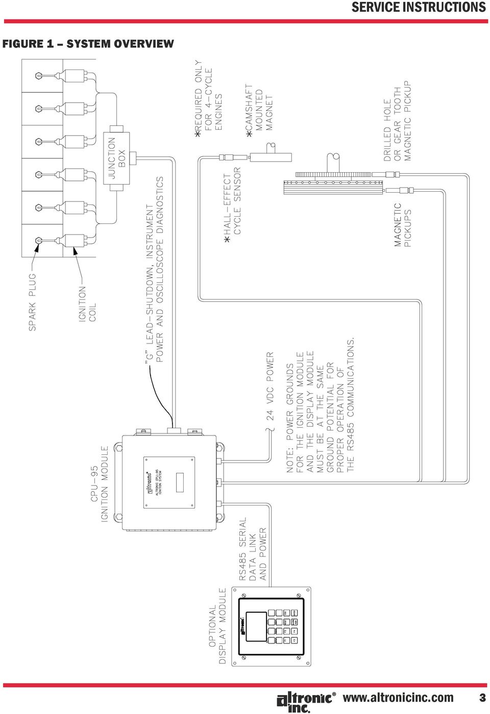
2 CPU-95 DIGITAL IGNITION SYSTEM 1.0 SYSTEM DESCRIPTION 1.1 The Altronic CPU-95, DC-powered ignition system is a microprocessor-based capacitor discharge system designed for application on natural gas fueled engines. The system features crankshaft-triggered timing accuracy and the capability to vary timing electronically by several means, including an external 4-20 ma control signal connected to the optional Display Module. The system is fieldprogrammable and offers a variety of advanced control methods, emissions reduction, primary and secondary spark diagnostics, self diagnostics, serial communications and engine protection features. 1.2 The CPU-95 ignition system consists of two main parts: an optional user interface Display Module and an engine mounted Ignition Module (SEE FIGURE 1). The optional Display Module has an alphanumeric back-lit LCD display that shows the operating status, engine RPM, energy level, single or double-striking mode, current loop input value, ignition timing, set-up, and diagnostic information. The Display Module is a means of monitoring or changing monitored parameters, all of the ignition system functions are performed in the Ignition Module. Five models of the Ignition Module are available: outputs, single storage capacitor outputs, single storage capacitor outputs, single storage capacitor outputs, dual storage capacitors outputs, single storage capacitor (VariSpark ) 1.3 Timing changes on the CPU-95 are derived by counting pulses from the reference teeth. The timing change increment is dependent on the number of holes or teeth being sensed. The minimum timing change is defined as follows (where N = number of holes or teeth): If N < 270, then increment = 45/N degrees. If N > 270, then increment = 90/N degrees. 1.4 Power requirement is 24 Vdc, 5 amperes nominal for typical applications (10 amperes for systems using the Ignition Module). REFER TO FORM CPU-95 II, SECTION FORM CPU-95 SI 4-08

3 FIGURE 1 SYSTEM OVERVIEW 3
4 CPU-95 DIGITAL IGNITION SYSTEM FIGURE 2 PARTS IDENTIFICATION 4 FORM CPU-95 SI 4-08

5 2.0 PARTS IDENTIFICATION AND SPECIFICATION 2.1 PARTS LIST - IGNITION MODULE ,-16,-18; ; SEE FIGURE 2 FIGURE & REFERENCE NO. QUANTITY PART NO. DESCRIPTION A EEprom, blank Microprocessor, ,-16 unit Microprocessor, unit Microprocessor, unit Microprocessor, unit Enclosure Gasket, connector -4a Screw b Cap, connector Fuse 15A Plug, 6-pin -6a Plug, 5-pin -6b Plug, 12-position Gasket, lid Screw Logic cover board Standoff Logic board assembly Logic shield board Standoff Power board assembly, unit Power board assembly, unit Power board assembly, unit Power board assembly, unit Power board assembly, unit Standoff, nylon Shock mount -16a Nut 5/ b Lockwasher 5/16-16c Ground strap -16d Bolt 5/ Conduit fitting Bottom plate -18a Screw b Gasket, plate A Label Screw Screw Screw Screw Insulator, T-MOS Insulator, voltage regulator 5

6 CPU-95 DIGITAL IGNITION SYSTEM FIGURE 3 PARTS IDENTIFICATION C US CERTIFIED CLASS I, DIV 2, GRP C & D, T4 6 FORM CPU-95 SI 4-08

7 2.2 PARTS LIST - CPU-95 DISPLAY MODULE x; SEE FIGURE 3 FIGURE & REFERENCE NO. QUANTITY PART NO. DESCRIPTION Spacer Front cover Keypad EPROM, S1 EPROM, S S2 EPROM, EPROM, EPROM, Screw Gasket, front cover Standoff Screw Terminal block Display board assembly, S Display board assembly, S Display board assembly, Display board assembly, Display board assembly, Gasket, back enclosure Back enclosure A Back label, ,-1S,-3, A Back label, PARTS LIST - CPU-95 ENHANCED DISPLAY MODULE FIGURE & REFERENCE NO. QUANTITY PART NO. DESCRIPTION Spacer Front cover Keypad -4 N/A Screw Gasket, front cover Standoff Screw Terminal block Display board assembly Gasket, back enclosure Back enclosure Back label 7

8 CPU-95 DIGITAL IGNITION SYSTEM 3.0 TEST STAND REQUIREMENTS 3.1 In order to test an Altronic CPU-95 ignition system, a special test stand is required. The basic test stand is similar to that required for the Altronic CPU-90 system. 3.2 The following items are required to test the Altronic CPU-95 system: A. A variable speed motor of 0.5 HP or greater, capable of rotating 1800 RPM with a standard ignition drive accepting either flange or base mounting. B. A spark degree wheel graduated in 360 increments with the indicator attached to the shaft common to the standard ignition drive. C. Sixteen (16) ignition coils connected to suitable, adjustable spark gaps. NOTE: THE TEST STAND SHOULD INCORPORATE EIGHTEEN (18) IGNITION COILS IF 18-OUTPUT UNITS WILL BE TESTED. D. A source of gear tooth pulses mechanically connected to the ignition drive; a 180-tooth gear is recommended. E. A single reset pin (6-32 steel machine screw recommended) mounted to the face of the gear. F. Magnetic pickups ( x) mounted to sense the gear teeth and the reset pin. G. A primary wiring harness connecting the ignition coils to the CPU-95 Ignition Module. This requires connector MS3108A-22-14S, Altronic part number NOTE: THE HARNESS IS WIRED DIFFERENTLY FOR 18-OUTPUT UNITS. H. A manual control loop unit to simulate the 4-20mA control signal. I. A DC power source capable of supplying 24Vdc, 5 amps (see Installation Instructions form CPU-95 II, section 9.2 and drawing ). J. An Altronic II-CPU Alternator; part no H is recommended. A distributor shaft assembly with 2:1 gear installed is required to test a 4-cycle application. The rotating magnet on the distributer shaft assembly must be over the Hall-effect switch when the reset pin on the test stand is opposite its magnetic pickup. K. An Altronic II-CPU back cover assembly or -2 and mating harness Connect the wiring harness as shown on the following page. L. A blank CPU-95 EEPROM, Altronic part number A. Test memories can be used if the Terminal Program is not used. Test memories for 16 and 18-cylinder, 4-cycle applications programmed with the number of teeth used on the test stand (usually 180) will be needed. M. Altronic CPU-95 Terminal Program part number CPU-95.MEM. NOTE: REFER- ENCE FORM CPU-95 PI, SECTION 1.3 FOR COMPUTER AND PERIPHERAL REQUIREMENTS FOR THE TERMINAL PROGRAM. N. A means to elevate the CPU-95 Ignition Module to a controlled temperature of 150 F (65 C). O. Altronic Test Unit can provide simulated pickup signals to exercise the CPU-95 outputs at a fixed firing rate. P. CPU-95 Display Module can be connected using a 4-conductor cable as shown in the Test Stand Wiring diagram. NOTE: SUPPLY POWER TO THE DISPLAY MODULE BY CONNECTING TWO OF THE FOUR CONDUC- TORS TO THE CPU-95 INPUT POWER TERMINALS. IF A SEPARATE SUPPLY IS USED TO POWER THE DISPLAY, THE GROUNDS MUST BE AT THE SAME POTENTIAL FOR PROPER OPERATION OF THE RS485 COMMUNICATIONS. 8 FORM CPU-95 SI 4-08

9 FIGURE 4 TEST STAND WIRING 4-CYCLE PICKUP INPUT WIRING CPU-95 INPUT X 5-PIN CONNECTOR DESCRIPTION A (4-cycle pickup) PIN E HALL EFFECT SWITCH (+) B (4-cycle pickup) PIN D HALL EFFECT SUPPLY (+) C (4-cycle pickup) PIN C HALL EFFECT COMMON (-) PIN B *SEE NOTE 1 PIN A *SEE NOTE 1 *Note 1: Connect leads A and B together (shorts the alternator output). 9
. www.altronicinc.")
10 CPU-95 DIGITAL IGNITION SYSTEM 4.0 TESTING PROCEDURE - CPU-95 IGNITION MODULE 4.1 VOLTAGE OUTPUT TEST: Using a known good Display Module, connect CPU-95 unit to test stand. REFERENCE FORM CPU-95 II FOR CORRECT WIRING OF UNIT AND CPU-95 OI FOR OPERATION OF UNIT. Set the Ignition Module for energy level 2 (E2). Operate the test stand at 300 RPM leaving the 19-pin output connector disconnected. Output voltage is measured from the G pin (+) to the J pin ( ). The output voltage should be 160 ±10 Vdc. 4.2 OPERATIONAL TESTS: With the system completely connected, perform the following tests on the Ignition Module. It is recommended that these tests be performed with the Ignition Module heated to a temperature of 150 F (65 C). The tests should be performed using a test EEPROM having the same number of teeth as the test stand, or program a blank EEPROM. A. 180 TOOTH GEAR RPM TEST 75 RPM All outputs fire a 15mm gap. 600 RPM All outputs fire a 15mm gap RPM All outputs fire a 15mm gap RPM Each output fires consistently in sequence; timing as follows starting with output A and proceeding in alphabetical sequence: 8-OUTPUT: A-B-C-D-E-F-K-L H4A180.FC OUTPUT: A-B-C-D-E-F-K-L-M-N-P-R-S-T-U-V P4A180.FC OUTPUT: A-B-C-D-E-F-G-H-K-L-M-N-P-R-S-T-U-V R4V180.FC NOTE: Perform remaining tests B. through G. at 1200 rpm. NOTE: This test is only valid with 8 and 16 output Ignition Modules; there is no connection to the storage capacitor in 18-output units. NOTE: Do not program over the original EEPROM. A P4A180.FC pattern is recommended for a 16-output unit and a R4V180.FC pattern for an 18-output unit, assuming the test stand uses a 180 tooth gear. B. The Display Module should read FIRING. The panel I/O switches should be as follows: Alarm Out - closed; Fault Out - closed; Fire Confirm Out - closed. C. The four internal LED s on the logic board should be as follows: Power - on; Rx - flashing; Tx - flashing; Alarm - off. D. Verify cylinder spark data number reads in accordance with form CPU-95 OI, SECTION E. Verify cylinder spark data number reacts in accordance with form CPU-95 OI, SECTION When the diagnostic flag is set the alarm out I/O switch on the panel should open and the Display Module should read WARNING VIEW DIAGNOSTICS. Verify that the proper warning and output identifier was captured (press DIAG key on Display Module). F. Ground the shutdown lead G (8 and 16 output units only). Ignition firings should immediately cease and the display should read SHUTDOWN. The panel I/O switches should be as follows: Alarm Out - closed; Fault Out - closed; Fire Confirm Out - open. G. Ground the Shutdown Input (all units). Ignition firings should immediately cease and the display should read SHUTDOWN. The panel I/O switches should be as follows: Alarm Out - closed; Fault Out - closed; Fire Confirm Out - open. 10 FORM CPU-95 SI 4-08

11 SEE FORM CPU-95 OI, SECTIONS 5.0 AND TIMING TESTS: The following tests should be performed on the Ignition Module to verify proper control of timing. Use a test Display Module. A. Enter the TIMING menu and test the GLOBAL RETARD. Vary the global timing and verify the timing changes on the spark wheel and on the Display Module (SEE FORM CPU-95 OI SECTION 5.0). B. Enter the TIMING menu and test the ONE-STEP RETARD. Ground the miscellaneous input and assure the timing retards by the one-step retard value (SEE CPU-95 OI SECTION 6.4). C. Enable CURRENT LOOP RETARD and test the 4-20mA CURRENT LOOP. Vary the input current by adjusting the connected to the Display Module and assure the timing changes in accordance with the unit s programmed curve (SEE CPU-95 OI SECTION 6.2). 5.0 OHMMETER CHECKS SEE SECTION IGNITION MODULE POWER BOARD: The following tests should be made using a Simpson Model 260 analog volt-ohmmeter (VOM) set to ohms. The ohmmeter scale should be set to R x 10,000. Readings outside the range indicated establish a defective Power Board. A Power Board passing the ohmmeter tests may still be defective and the full test should be performed using an oscilloscope to confirm correct operation. A. Check the resistance with the positive lead of the ohmmeter connected to the G lead and the negative lead connected to each output pin of the output connector. If ohmmeter reading is less than 250,000 ohms replace Power Board (2-14). B. Check the resistance with the negative lead of the ohmmeter connected to the G lead and the positive lead connected to each output pin of the output connector. If ohmmeter reading is less than 250,000 ohms replace Power Board (2-14). NOTE: THE J LEAD IS NOT AN OUTPUT PIN. 6.0 OSCILLOSCOPE TESTS 6.1 TEST SET-UP: Two 100:1 oscilloscope probes are required. Test speed is 1000 RPM. 6.2 STORAGE CAPACITOR VOLTAGE PATTERN (8 and 16 output units only) A. Connect he trigger input of the oscilloscope to the A primary coil lead. NOTE: This is a 140 to 180 volt, positive polarity signal. B. Connect the oscilloscope reading probe to the G lead to view all outputs. SEE NORMAL PATTERN ON NEXT PAGE. C. Verify peak output voltage is: 140±10 volts for energy level E1 160±10 volts for energy level E2 180±10 volts for energy level E3 6.3 MULTI-STRIKE TESTS ( and series only) A. Set Unit to MULTI-STRIKE mode via Display Module keypad. B. Verify timing of all outputs using the table in section 4.2 A Series: Verify all outputs have two firings. The separation will vary with rpm and should equal 7 degrees at 1000 rpm. The second firing is automatically turned off above 1050 rpm Series: Verify a longer duration spark on the degree wheel compared to normal mode. C. 8 and 16 Output Units Only: Connect oscilloscope to the G lead and view pattern. Discharge waveform should appear as shown on the next page. 11
. 5.0 OHMMETER CHECKS SEE SECTION 6.")
12 CPU-95 DIGITAL IGNITION SYSTEM NORMAL PATTERN (ALL UNITS) MULTISTRIKE PATTERN ( X) VARISPARK PATTERN ( X) 7.0 TESTING PROCEDURE - DISPLAY MODULE 7.1 OPERATIONAL TESTS: Connect the Display Module to a test Ignition Module known to be operational. A. Apply 24Vdc input power to both units and verify Display Module communicates with Ignition Module. Display should read READY. B. Hold down ENTER key for approximately six seconds to access keypad test, depress each key and verify that a unique number (0-15) is identified for each key. C. Start rotation of test stand motor and increase speed to 300 RPM. Display should read FIRING. With spark wheel turned on and firing output A at zero degrees, verify current loop operates as programmed and that Display Module shows the correct loop value (4-20mA). D. Ground miscellaneous input on Display Module and verify ONE-STEP timing retards the amount stored in the ONE-STEP timing value. SEE INSTALLATION INSTRUCTIONS FORM CPU-95 II FOR CORRECT WIR- ING AND OPERATING INSTRUCTIONS FORM CPU-95 OI FOR OPERATION OF THE DISPLAY MODULE. NOTE: Ground only the miscellaneous input on Display Module and not on Ignition Module. 12 FORM CPU-95 SI 4-08

13 8.0 TROUBLESHOOTING Perform all tests at a test stand speed of 1000 RPM with a 4-cycle test memory. The following tests assume an adequate 24 Vdc power source and properly installed magnetic and Hall-effect pickups. 8.1 IGNITION MODULE: The following tests are to be performed with a known good Display Module. PROBLEM TEST TEST INDICATION CORRECTIVE ACTION (Fig. 2) No output Section 4.1 No voltage Replace power board (14)* No output Section 4.1 Low voltage Replace power board (14) One output does not fire Only one output fires No Multi-Strike function Panel I/O switches malfunction Incorrect or missing cylinder spark data Unit does not acknowledge SHUTDOWN Section 4.2/6.2 Section 4.2/6.2 Section 6.3 Section 4.2 B, C Section 4.2 D, E Section 4.2 F, G Missing discharge on stand or scope Only one spark gap is firing Outputs do not have second firing Does not function as described Sets non-existent WARNINGS on display, always reads 0 or 255 Unit continues to fire Timing varies Section 4.2 A Timing other than as shown Timing control malfunctions Section 4.3 * May indicate a defective power or logic board. Timing does not change or changes incorrectly Replace power board (14) Replace power board (14) Measure voltage from pin 4 to Vss of large ribbon cable on logic board. If voltage is 5V. in Multi-Strike mode, replace power board (14). If voltage is 4V. or less and Display Module shows Multi-Strike identifier, replace logic board (11) Replace logic board (11) Replace power board (14)* Fails section 4.2 F, replace power board (14) Fails section 4.2 G, replace logic board (11) Replace logic board (11) Replace logic board (11) 8.2 DISPLAY MODULE: The following tests are to be performed with a known good Ignition Module. PROBLEM TEST TEST INDICATION CORRECTIVE ACTION (Fig. 3) No function from Display Module No response from one or more keys No current loop function No One-Step function Section 7.1 A Section 7.1 B Section 7.1 C Section 7.1 D No display or no communications* Missing or wrong key identifier Timing does not change or changes incorrectly Timing does not change * Display Module reads COMMUNICATIONS PROBLEM ** May indicate a defective display board or defective keypad Replace display board (10) Replace display board (10)** Replace display board (10) Replace display board (10) 13
* No output Section 4.")
14 CPU-95 DIGITAL IGNITION SYSTEM 9.0 BOARD REPLACEMENT PROCEDURE IGNITION MODULE LOGIC BOARD 9.1 DISASSEMBLY PROCEDURE (REFER TO FIGURE 2) A. Remove four screws (8) from cover board (9) and remove cover board. B. Remove four standoffs (10) from logic board (11). C. Carefully unplug four conductor ribbon cable from logic board and fifteen conductor ribbon cable from power board (14). Logic board can now be removed from enclosure (3). D. Remove four screws (21) and separate logic board from shield board (12). 9.2 ASSEMBLY PROCEDURE (REFER TO FIGURE 2) A. Attach shield board (12) to logic board (11) using four screws (21). B. Install logic board in enclosure (3). C. Plug fifteen conductor ribbon cable into power board (14) and four conductor ribbon cable into logic board. D. Install and tighten four standoffs (10). E. Replace cover board (9) and secure with four screws (8). F. Retest per SECTION BOARD REPLACEMENT PROCEDURE IGNITION MODULE POWER BOARD 10.1 DISASSEMBLY PROCEDURE (REFER TO FIGURE 2) A. Remove logic board (refer to section 9.1). B. Remove four screws (22, 23) from bottom of enclosure (3). C. Remove four standoffs (13). D. Remove four screws (4a) from connector on side of enclosure and push connector into box. E. Power board (14) can now be removed from enclosure ASSEMBLY PROCEDURE (REFER TO FIGURE 2) A. Wipe inside of enclosure with a clean rag. Examine insulators (24, 25) and replace if damaged. B. Insert power board (14) into enclosure (3). C. Install four new screws (22, 23) through bottom of enclosure and tighten securely. D. Replace connector gasket (4) and insert connector through enclosure hole. Orient connector key to top of enclosure. E. Using four new screws (4a) secure connector in enclosure. F. Install four standoffs (13) and tighten power board securely. G. Install logic board (REFER TO SECTION 9.2). H. Retest per section 4.0, FORM CPU-95 SI 4-08
 and separate logic board from shield board (12). 9.2 ASSEMBLY PROCEDURE (REFER TO FIGURE 2) A. Attach shield board (12) to logic board (11) using four screws (21). B.")
15 11.0 BOARD REPLACEMENT PROCEDURE DISPLAY MODULE DISPLAY BOARD 11.1 DISASSEMBLY PROCEDURE (REFER TO FIGURE 3) A. Loosen four screws (5) holding front cover (2) to back enclosure (12). Leaving screws in front cover pull back enclosure away. B. Remove three screws (8) holding display board assembly (10). C. Unplug keypad ribbon cable and remove display board assembly ASSEMBLY PROCEDURE (REFER TO FIGURE 3) A. Plug keypad ribbon cable into display board assembly (10). B. Install and tighten three screws (8) securing display board assembly. C. Verify back enclosure and front cover gaskets (11, 6) are in good condition and replace if necessary. D. Place front cover (2) and back enclosure (11) together and start four screws (5). E. Verify front cover gasket is aligned and alternately tighten four screws (2) until secure. F. Retest per SECTION
 are in good condition and replace if necessary. D. Place front cover (2) and back enclosure (11) together and start four screws (5). E.")
Fan Coil EC Motor Control
 Fan Coil EC Motor Control G3 PWM BARD The Enviro-Tec Generation 3 PWM (G3 PWM) board provides a pulse-width modulated (PWM) signal to the EC motor to control fan speed. The board is factory programmed
12-Volt Negative Ground Installation Instructions
 12-Volt Negative Ground Installation Instructions For Part Number: 1141, 1164, 1165, 1181 CAUTION!!! Before installing, please read the following important information... 1. The Ignitor is designed for
TraceTek TTDM Series Leak Detection and Location Modules Replacement Parts Installation Instructions
 TraceTek TTDM Series Leak Detection and Location Modules Replacement Parts Installation Instructions TRACETEK TraceTek TTDM Replacement Parts General Information These instructions detail the steps to
FUEL-16, Troubleshooting Fuel Supply Problems
 FUEL-16, Troubleshooting Fuel Supply Problems Introduction This procedure is used to troubleshooting fuel supply problems including failure of the fuel pump to start during engine cranking. Fuel Pump Not
Quickie Rhapsody Service Manual
 Quickie Rhapsody Service Manual 2006 Sunrise Medical Inc. 101976 Rev A Quickie Rhapsody Service Manual Contents Introduction... 0.1 VR2 Controller... 0.2 Plugs/Connectors... 0.3 Basic Tool List & Main
Automotive Sensor Simulator. Automotive sensor simulator. Operating manual. AutoSim
 Automotive sensor simulator Operating manual AutoSim Contents Introduction.. page 3 Technical specifications.... page 4 Typical application of AutoSim simulator..... page 4 Device appearance... page 5
ANTI-THEFT SYSTEM. 1995 Volvo 850 DESCRIPTION & OPERATION BASIC ALARM. 1995-96 ACCESSORIES & EQUIPMENT Volvo Anti-Theft Systems
 ANTI-THEFT SYSTEM 1995 Volvo 850 1995-96 ACCESSORIES & EQUIPMENT Volvo Anti-Theft Systems 850 DESCRIPTION & OPERATION WARNING: Deactivate air bag system before performing any service operation. For 1995
ECM. Service Guide. www.thedealertoolbox.com
 ECM Service Guide www.thedealertoolbox.com ECM Table of Contents Service Guide Working on the motor with power connected may result in electrical shock or other conditions that may cause personal injury,
Current Probes. User Manual
 Current Probes User Manual ETS-Lindgren L.P. reserves the right to make changes to any product described herein in order to improve function, design, or for any other reason. Nothing contained herein shall
Troubleshooting accelerometer installations
 Troubleshooting accelerometer installations Accelerometer based monitoring systems can be tested to verify proper installation and operation. Testing ensures data integrity and can identify most problems.
Automatic Transfer Switch FT-10 Network Control Communications Module (CCM-T) Kit 541 0811
 Kit 541 0811") Instruction Sheet 1-2003 Automatic Transfer Switch FT-10 Network Control Communications Module (CCM-T) Kit 541 0811 PURPOSE OF KIT A CCM-T is used to monitor and control an automatic transfer switch. The
Instruction Sheet 1-2003 Automatic Transfer Switch FT-10 Network Control Communications Module (CCM-T) Kit 541 0811 PURPOSE OF KIT A CCM-T is used to monitor and control an automatic transfer switch. The
INSTRUMENT PANEL. 1995 Volvo 850 DESCRIPTION & OPERATION. 1995-96 ACCESSORIES & EQUIPMENT Volvo Instrument Panels
 INSTRUMENT PANEL 1995 Volvo 850 1995-96 ACCESSORIES & EQUIPMENT Volvo Instrument Panels 850 WARNING: When working around steering column and before performing repairs, disconnect and shield battery ground
PUSH BUTTON START INSTALLATION MANUAL
 PUSH BUTTON START INSTALLATION MANUAL ALTHOUGH THIS PRODUCT HAS BEEN THOROUGHLY TESTED KPIERSON TECHNOLOGIES ASSUMES NO RESPONSIBILITY FOR ANY DAMAGE THAT MAY RESULT BY THE INSTALLATION OF THIS PRODUCT.
User Manual. Instructions for installing the Sure Stitch on the Next Generation Quilting Frame. Parts Included:
 User Manual Instructions for installing the Sure Stitch on the Next Generation Quilting Frame. Parts Included: 1: Display Console 1: Control Box 2: Encoder (Wires attached) (Not Shown) 1: 5v Power Supply
MODEL 5010 DUAL CHANNEL SMOKE/FIRE DETECTION MODULE
 DESCRIPTION MODEL 5010 DUAL CHANNEL SMOKE/FIRE DETECTION MODULE DESCRIPTION The SST Model 5010 Two Channel Smoke/Fire Detection Module provides two independent detection input channels for the NOVA-5000
Describe the procedure used to check for spark. Discuss what to inspect and look for during a visual inspection of the ignition system.
 CHAPTER 20 OBJECTIVES Describe the procedure used to check for spark. Discuss what to inspect and look for during a visual inspection of the ignition system. List the steps necessary to check and/or adjust
SELECTION, APPLICATION AND MAINTENANCE
 DIESEL PROTECTION SYSTEMS Automatic Diesel Engine Shut Down System for Safe Area Applications SELECTION, APPLICATION AND MAINTENANCE Series 300 Series 310 SYSTEM DESCRIPTION Suitable for attended engine
LG Air Conditioning Multi F(DX) Fault Codes Sheet. Multi Split Units
 Fault Codes Sheet. Multi Split Units") Multi Split Units If there is a fault on any LG Multi unit, an Error mark is indicated on the display window of the indoor unit, wired-remote controller, and LED s of outdoor unit control board. A two
Multi Split Units If there is a fault on any LG Multi unit, an Error mark is indicated on the display window of the indoor unit, wired-remote controller, and LED s of outdoor unit control board. A two
INSTALLATION INSTRUCTIONS
 LIGHTING CONTROL PANELS 4 AND 8 RELAYS INSTALLATION INSTRUCTIONS INSTALLATION OVERVIEW The installation instructions contained in this document are provided as a guide for proper and reliable installation.
User Manual for CH-PFC76810
 AA Portable Power Corp www.batteryspace.com, Email: Sales@batteryspace.com User Manual for CH-PFC76810 1. Overview The CH-PFC76810 charger is suitable for charging lithium ion battery packs such as those
T7560A,B,C Digital Wall Module
 T7560A,B,C Digital Wall Module HONEYWELL EXCEL 5000 OPEN SYSTEM BEFORE INSTALLATION All wiring must comply with local electrical codes and ordinances or as specified on installation wiring diagrams. Digital
http://waterheatertimer.org/how-to-troubleshoot-gas-water-heater.html
 http://waterheatertimer.org/how-to-troubleshoot-gas-water-heater.html TECHNICAL SERVICE DEPARTMENT Effective October 2007, we transitioned to the White Rodgers (Intelli-Vent TM )Thermostat Control for
PowerFlex 700S and 700H Frame 12 DC Bus Connector Kit
 PowerFlex 700S and 700H Frame 12 DC Bus Connector Kit Installation Instructions This document provides instructions for the installation of a DC bus connector kit for PowerFlex 700S and 700H frame 12 drives
SECTION G2: CABLE PROCESSOR MODULE MAINTENANCE
 SECTION G2: CABLE PROCESSOR MODULE MAINTENANCE Cable Processor Module overview WARNING! When tipping the Cable Processor Module back, (after removing the toggle arm pin), use extreme caution not to drop
VEHICLE THEFT/SECURITY SYSTEMS
 DN VEHICLE THEFT/SECURITY SYSTEMS 8Q - 1 VEHICLE THEFT/SECURITY SYSTEMS TABLE OF CONTENTS page GENERAL INFORMATION INTRODUCTION...1 VEHICLE THEFT SECURITY SYSTEM....1 ENABLING...1 ARMING...1 DISARMING...2
2001 Mercedes-Benz ML320
 MODEL IDENTIFICATION 2001-04 STARTING & CHARGING SYSTEMS Starters - 163 Chassis WARNING: Vehicles are equipped with air bag supplemental restraint system. Before attempting any repairs involving steering
EXM-E3 Memory Module Upgrade for ALESIS Fusion 6/8HD (S60/S80) & AKAI MPC5000
 & AKAI MPC5000") EXM-E3 Memory Module Upgrade for ALESIS Fusion 6/8HD (S60/S80) & AKAI MPC5000 This document is split into four sections: 1. Alesis Fusion 6HD (S60) Disassembly Procedure. 2. Alesis Fusion 8HD (S80) Disassembly
EXM-E3 Memory Module Upgrade for ALESIS Fusion 6/8HD (S60/S80) & AKAI MPC5000 This document is split into four sections: 1. Alesis Fusion 6HD (S60) Disassembly Procedure. 2. Alesis Fusion 8HD (S80) Disassembly
* DISCLAIMER: Contents. How to Use This Guide: COMMERCIAL INSTALL GUIDE 2
 COMMERCIAL INSTALL GUIDE 2 Contents How to Use This Guide: The first section of this guide is designed to assist you with the installation of your DECK Monitoring hardware. The revenue grade meter and
E2 Series Electric Furnaces
 E2 Series Electric Furnaces Service Manual Table of Contents Electrical Requirements... 10 Codes, Specifications Requirements... 10 Connection Supply Service Wires... 10 Furnace Sequence of Operation...
Electronically Controlled Air Suspension (ECAS) for Trucks
 for Trucks") $2.50 Electronically Controlled Air Suspension (ECAS) for Trucks Maintenance Manual No. 36 Issued 7-99 ECAS System for 6 x 2 and 6 x 4 Vehicles with Rear Air Suspensions Service Notes Service Notes This
$2.50 Electronically Controlled Air Suspension (ECAS) for Trucks Maintenance Manual No. 36 Issued 7-99 ECAS System for 6 x 2 and 6 x 4 Vehicles with Rear Air Suspensions Service Notes Service Notes This
www.sebury.com.cn Digital Keypad Use s Manual
 K3 K4 www.sebury.com.cn Digital Keypad Use s Manual Contents Introduction Introduction Specifications Intramural Interface Circuit 3 Mounting 3 Wiring 5 Power UP 7 Engineer Programming Mode 7 The K3/K4
RI-215A Operator s Manual. Part Number: 71-0045RK Revision 0 Released: 10/3/05
 RI-215A Operator s Manual Part Number: 71-0045RK Revision 0 Released: 10/3/05 Warranty RKI Instruments, Inc., warrants gas alarm equipment sold by us to be free from defects in materials and workmanship,
ATL Fuel Level Sender Probes
 T E C H N I C A L S P E C I F I C A T I O N The ATL EL-AD-151 (Resistance Output) and EL-AD-152 (Voltage Output) Fuel Level Senders are highly advanced sensors for continuously measuring the contents of
Troubleshooting and Diagnostics
 Troubleshooting and Diagnostics The troubleshooting and diagnostics guide provides instructions to assist in tracking down the source of many basic controller installation problems. If there is a problem
430 Power/Electronics Replacement
 Replacing the main board WARNING Before proceeding, turn off the main power switch and unplug the power cord. Caution Make sure you are properly grounded with an ESD strap before continuing. The main printed
RADIANT PLASMA 4700 Plasma Spark Generator
 RADIANT PLASMA 4700 Plasma Spark Generator Installation Guide / User Manual A S P A R K O F F R E S H A I R Aquapulser.com Contents 1 Introduction 2 1.1 About the Product....................................
DESCRIPTION. DTC P0351 Ignition Coil "A" Primary / Secondary Circuit. DTC P0352 Ignition Coil "B" Primary / Secondary Circuit
 1 of 10 6/4/2012 10:38 PM Last Modified: 3-27-2012 6.4 C From: 201203 Model Year: 2013 Model: FR-S Doc ID: RM000000XH40PUX Title: FA20 ENGINE CONTROL: SFI SYSTEM: P0351-P0354: Ignition Coil "A" Primary
SECURITY SYSTEM SMART SIREN KIT
 -J00876 REV. 009-0-09 SECURITY SYSTEM SMART SIREN KIT GENERAL Kit Number 688-0 Models For model fitment information, see the P&A Retail Catalog or the Parts and Accessories section of www.harley-davidson.com
Essential Electrical Concepts
 Essential Electrical Concepts Introduction Modern vehicles incorporate many electrical and electronic components and systems: Audio Lights Navigation Engine control Transmission control Braking and traction
12 Volt 30 Amp Digital Solar Charge Controller
 12 Volt 30 Amp Digital Solar Charge Controller User s Manual WARNING Read carefully and understand all INSTRUCTIONS before operating. Failure to follow the safety rules and other basic safety precautions
DIGITAL ALARM II FOR HOSPITALS AND LABORATORIES INSTALLATION AND OPERATING INSTRUCTIONS 52 635.0
 Form No. 74-00-4001 S168-195-001 Revision E DIGITAL ALARM II FOR HOSPITALS AND LABORATORIES INSTALLATION AND OPERATING INSTRUCTIONS 52 635.0 INTRODUCTION Allied Healthcare Products, Inc. s Digital Alarm
Whale 3. User Manual and Installation Guide. DC Servo drive. Contents. 1. Safety, policy and warranty. 1.1. Safety notes. 1.2. Policy. 1.3. Warranty.
 Whale 3 DC Servo drive User Manual and Installation Guide Contents 1. Safety, policy and warranty. 1.1. Safety notes. 1.2. Policy. 1.3. Warranty. 2. Electric specifications. 2.1.Operation ranges. 3. Connections
ETC TWO STAGE ELECTRONIC TEMPERATURE CONTROL
 RANCO INSTALLATION INSTRUCTIONS ETC TWO STAGE ELECTRONIC TEMPERATURE CONTROL Relay Electrical Ratings PRODUCT DESCRIPTION The Ranco ETC is a microprocessor-based family of electronic temperature controls,
CHAPTER 11: Flip Flops
 CHAPTER 11: Flip Flops In this chapter, you will be building the part of the circuit that controls the command sequencing. The required circuit must operate the counter and the memory chip. When the teach
Battery Charger For Nickel Cadmium and Nickel-Metal Hydride Rechargeable Batteries Model PSN Series
 Battery Charger For Nickel Cadmium and Nickel-Metal Hydride Rechargeable Batteries Model PSN Series Operating Instructions WARNING CONCERNING THE REMOVAL OF COVER: CAUTION: TO PREVENT THE RISK OF ELECTRIC
VEHICLE SPEED CONTROL SYSTEM
 PL VEHICLE SPEED CONTROL SYSTEM 8H - 1 VEHICLE SPEED CONTROL SYSTEM TABLE OF CONTENTS page DESCRIPTION AND SPEED CONTROL SYSTEM...1 SPEED CONTROL SERVO-PCM OUTPUT....2 SPEED CONTROL SWITCHES PCM INPUT...2
1955-1956 Chevy Bel-Era
 Classic Instruments 1955-1956 Chevy Bel-Era Installation Manual Revised January 2, 2014 Page 1 Table of Contents Table of Contents 2 Welcome to the Team of Classic Instruments! 3 55-56 Chevy Part Identification
ECM Blower Motor Replacement Controls Programming Process
 COMPONENT PARTS SERIES Installation, Operation & Maintenance Instructions TABLE OF CONTENTS Section 1: Field Troubleshooting Procedures 2 Section 2: Field Control Replacement Procedure 3 ECM Connections
Oil and Coolant Circulating Heating System. Model - OCSM
 Oil and Coolant Circulating Heating System Model - OCSM Installation & Operation Manual 216280-000 REV 2 Identifying Your System The HOTSTART heating system is designed to heat fluids for use in marine
ABB Drives. User s Manual. Pulse Encoder Interface Module RTAC-01
 ABB Drives User s Manual Pulse Encoder Interface Module RTAC-0 Pulse Encoder Interface Module RTAC-0 User s Manual 3AFE 64486853 REV A EN EFFECTIVE:.5.00 00 ABB Oy. All Rights Reserved. Safety instructions
Advantium 2 Plus Alarm
 ADI 9510-B Advantium 2 Plus Alarm INSTALLATION AND OPERATING INSTRUCTIONS Carefully Read These Instructions Before Operating Carefully Read These Controls Corporation of America 1501 Harpers Road Virginia
Installation Instructions for FT-10 Network PowerCommand ATS Communication Module (NCM) Kits 541 0812 and 541 0868
 Kits 541 0812 and 541 0868") Instruction Sheet 10-2004 Installation Instructions for FT-10 Network PowerCommand ATS Communication Module (NCM) Kits 541 0812 and 541 0868 PowerCommand is a registered trademark of Cummins Inc. InPower
Instruction Sheet 10-2004 Installation Instructions for FT-10 Network PowerCommand ATS Communication Module (NCM) Kits 541 0812 and 541 0868 PowerCommand is a registered trademark of Cummins Inc. InPower
TROUBLESHOOTING GUIDE
 TROUBLESHOOTING GUIDE LESTRONIC II BATTERY CHARGER FOR MOTIVE POWER BATTERIES PLEASE SAVE THESE IMPORTANT SAFETY AND OPERATING INSTRUCTIONS For correct operation of the equipment, it is important to read
PowerFlex 700H and 700S AC Drives Frame 11 Main Fan Capacitor Replacement Kit
 Installation Instructions PowerFlex 700H and 700S AC Drives Frame 11 Main Fan Capacitor Replacement Kit ATTENTION: The sheet metal cover and mounting screws on the ASIC Board located on the power structure
WE-350 Series ¼ Turn Electric Actuator
 WE-350 Series ¼ Turn Electric Actuator Operation and Installation Manual Pg 1 (Rev. 020113) Table of Contents 1.0 General 1.1 Pre-Installation Inspection 1.2 Storage 1.3 Features & General Information
EVBIKE LCD Display Control User Guide. EVBIKE LCD Display Control User Guide WWW.EVBIKE.CZ - 1 -
 EVBIKE LCD Display Control User Guide WWW.EVBIKE.CZ - 1 - Table of Contents: 1) Description of the individual components and installation 2) Description of the measured quantities and user control display
Duct Humidity Transmitter
 SDC-H Duct Humidity Transmitter Features Replaceable sensor element Humidity measurement for air ducts Minimum and maximum value memory 0 0V, 0 0mA or 0V, 4 0mA measuring signals selectable with jumpers
RMM2 Heat-Tracing Remote Monitoring Module for the Raychem NGC Control System Installation Instructions
 Heat-Tracing Remote Monitoring Module for the NGC Control System Installation Instructions Tools Required 3 mm slotted screwdriver 3/8 hex key (for -4X only) Approvals Nonhazardous locations Type NM LISTED
FG MOISTURE MONITOR Installation & Operation Manual
 FG MOISTURE MONITOR Installation & Operation Manual Issue 3.0 7/20/10 1 Contents SERVICE AND TECHNICAL SUPPORT... 2 INSTALLATION:... 3 MOISTURE SENSOR INSTALLATION:... 3 SENSOR CONNECTOR:... 5 MONITOR
OPL BASIC. Dosing System for Professional Laundry machines. Contents
 OPL BASIC Dosing System for Professional Laundry machines Contents 1 Getting Started. Page 2 2 Installation. Page 4 3 Set Up & Operation. Page 8 4 Maintenance & Accessories. Page 10 5 Troubleshooting Page
G670 Intermittent Pilot Ignition Controls
 Installation Sheets Manual 121 Gas Combustion Combination Controls and Systems Section G Technical Bulletin Issue Date 0300 Intermittent Pilot Ignition Controls Figure 1: Intermittent Pilot Ignition Control
PowerLogic Sub Meter Display (SMD and SMDOPN)
") Instruction Bulletin Z203742-0B PowerLogic Sub Display (SMD and SMDOPN) CONTENTS Introduction... 2 Parts of the Sub Display... 3 Dimensional Drawing... 4 Installation... 5 Mounting the SMD... 5 Mounting
Instruction Bulletin Z203742-0B PowerLogic Sub Display (SMD and SMDOPN) CONTENTS Introduction... 2 Parts of the Sub Display... 3 Dimensional Drawing... 4 Installation... 5 Mounting the SMD... 5 Mounting
Modular I/O System Analog and Digital Interface Modules
 OPERATING INSTRUCTIONS Modular I/O System Analog and Digital Interface Modules Installation Operation Maintenance Document Information Document ID Title: Operating Instructions Modular I/O System Part
1993 ACCESSORIES & EQUIPMENT Volkswagen Instrument Panels. Volkswagen; EuroVan, Passat
 Article Text Saturday, March 18, 2000 10:33PM ARTICLE BEGINNING 1993 ACCESSORIES & EQUIPMENT Volkswagen Instrument Panels Volkswagen; EuroVan, Passat DESCRIPTION & OPERATION Instrument cluster for most
Back-UPS Pro 1300/1500 Installation and Operation
 Back-UPS Pro 1300/1500 Installation and Operation Inventory Safety Do not install the Back-UPS in direct sunlight, in excessive heat, humidity, or in contact with fluids. Connect the battery bu059a bu058a
with MERCURY FREE 1 HP Relays ! WARNING Before using this product read and understand instructions.
 B Installation & Maintenance Instructions MM-414 Series 150E and 157E Low Water Cut-Off/Pump Controllers For Steam Boilers and Other Level Control Applications A Typical Applications: Primary or secondary
ABB Drives. User s Manual HTL Encoder Interface FEN-31
 ABB Drives User s Manual HTL Encoder Interface FEN-31 HTL Encoder Interface FEN-31 User s Manual 3AUA0000031044 Rev B EN EFFECTIVE: 2010-04-06 2010 ABB Oy. All Rights Reserved. 5 Safety instructions
ECEN 1400, Introduction to Analog and Digital Electronics
 ECEN 1400, Introduction to Analog and Digital Electronics Lab 4: Power supply 1 INTRODUCTION This lab will span two lab periods. In this lab, you will create the power supply that transforms the AC wall
cbperformance.com Please read this entire brochure prior to installing your CB Performance Products MAGNASPARK II distributor.
 - Easy -wire installation with no external spark box necessary, but can be used with one. - Precision CNC machining and hand assembled construction. This is a premium product. - Accurate super hot spark
PRODUCTIVITY THROUGH INNOVATION 600 CONTROL DIRECT DRIVE TECHNICAL/OPERATION MANUAL
 Rev. D PRODUCTIVITY THROUGH INNOVATION 600 CONTROL DIRECT DRIVE TECHNICAL/OPERATION MANUAL 10 BORIGHT AVENUE, KENILWORTH NEW JERSEY 07033 TELEPHONE: 800-524-0273 FAX: 908-686-9317 TABLE OF CONTENTS Page
Battery Chargers. Revised 8/00 Form Number 56041170 FORM NO. 56041170 / BATTERY CHARGER SERVICE MANUAL / PARTS LIST - 45
 Battery Chargers SERVICE MANUAL / PARTS LIST AUTOMATIC Advance MODELS 0980, 098, 797, 8809, 90, 880, 880, 099, 08,, 09788, 098, 7, 097, 70, 790, 889 Lester MODELS 007,, 8, 8, 89, 80, 9, 00, 00, 008 MANUAL
IQ SYSTEM DISPLAY MODULE (IQDM-P) OWNER S MANUAL
 OWNER S MANUAL") IQ SYSTEM MODULE (IQDM-P) OWNER S MANUAL The IQDM is a handheld programming and diagnostic tool for use with Club Car IQ System vehicles. This owner s manual includes all information required to operate
IQ SYSTEM MODULE (IQDM-P) OWNER S MANUAL The IQDM is a handheld programming and diagnostic tool for use with Club Car IQ System vehicles. This owner s manual includes all information required to operate
i ChatterBox! Motorcycle Security
 i Before you Start the Installation * Please read this manual to become familiar with the requirements necessary to complete the installation. * Use a high quality multi-meter to test all wires before
ELECTRIC KNIFE SHARPENER
 PRODUCT MANUAL- M109 MODEL 401 ELECTRIC KNIFE SHARPENER Please read thoroughly before operation and keep for future reference Model 401 Knife Sharpener Specifications Model No. #401 Power Requirements
2. Remove rear cover of head lamp if bulbs are covered/sealed within the housings, and remove halogen bulb carefully.
 These instructions are designed to address most general installation procedures across vehicles and should not be considered vehicle make, model or year specific. Please contact the vendor directly for
ELECTRONIC THERMOSTAT AND THERMOMETER With SPEED CONTROL
 148 OLD CONCORD TURNPIKE, BARRINGTON NH 03825 USA TEL (603) 868-5720 FAX (603) 868-1040 1-800-435-6708 E-Mail:sales@seafrost.com www.seafrost.com ELECTRONIC THERMOSTAT AND THERMOMETER With SPEED CONTROL
SIMPLE ELECTRONIC IGNITION WIRE DIAGRAM THERMOSTAT (3) PV PILOT BURNER/IGNITOR - SENSOR Q345A (9) SPARK (4) GND (BURNER) CHASSIS GND
 PV PILOT BURNER/IGNITOR - SENSOR Q345A (9) SPARK (4) GND (BURNER) CHASSIS GND") Honeywell Electronic Ignition Troubleshooting Tech Tip April 2007 The Honeywell S8610H Intermittent Pilot Module provides the ignition sequencing, pilot spark, pilot flame monitoring, Pilot Valve (PV)
Honeywell Electronic Ignition Troubleshooting Tech Tip April 2007 The Honeywell S8610H Intermittent Pilot Module provides the ignition sequencing, pilot spark, pilot flame monitoring, Pilot Valve (PV)
VEHICLE THEFT/SECURITY SYSTEM
 PL VEHICLE THEFT/SECURITY SYSTEM 8Q - 1 VEHICLE THEFT/SECURITY SYSTEM TABLE OF CONTENTS page DESCRIPTION AND OPERATION INTRODUCTION...1 VEHICLE THEFT/SECURITY SYSTEM (VTSS)... 1 (SKIS)... 2 SENTRY KEY
CAUTION OPC-LM1-ID. Option Card for Frequency Divider. Fuji Electric FA Components & Systems Co., Ltd. Instruction Manual
 Instruction Manual Option Card for Frequency Divider Deliver this instruction manual without fail to those who actually operate the equipment. Read this operation manual and understand the description
Fuel Injection Pump, Rotary (005-014)
") Fuel Injection Pump, Rotary View Related Topic Page 1 of 30 Fuel Injection Pump, Rotary (005-014) Table of Contents Summary General Information Preparatory Steps Remove Front Gear Train Rear Gear Train
Fuel Injection Pump, Rotary View Related Topic Page 1 of 30 Fuel Injection Pump, Rotary (005-014) Table of Contents Summary General Information Preparatory Steps Remove Front Gear Train Rear Gear Train
Digi-Motor Installation Guide
 Digi-Motor Installation Guide Installation Video...located at marsdelivers.com Digi-Motor Installation Guide Digi-Motor For technical assistance with your Azure Digi-Motor, call the MARS technical support
Installation and Operation Manual. Digital Remote Meter for Monitoring System Performance. Version: RM-1
 REMOTE METER TM Installation and Operation Manual. Digital Remote Meter for Monitoring System Performance. Version: RM-1 1098 Washington Crossing Road Washington Crossing, PA 18977 USA www.morningstarcorp.com
SIMATIC S7-300. Getting Started for First Time Users. Order No.: 6ZB5310-0NC02-0BA0 04/2007 A5E01094750-01
 SIMATIC S7-300 Getting Started for First Time Users Order No.: 6ZB5310-0NC02-0BA0 04/2007 A5E01094750-01 Safety Guidelines This manual contains notices you have to observe in order to ensure your personal
SERVICE GUIDE For WARN PULLZALL 120v AC &100v AC P/N 685000 & 685001
 SERVICE GUIDE For WARN PULLZALL 120v AC &100v AC P/N 685000 & 685001 REPAIR / REPLACEMENT INSTRUCTIONS TROUBLE SHOOTING GUIDE 986765A2.doc Page 1 of 50 WARNING This guide identifies potential hazards and
Series 6000 Torque measured metal bellow coupling
 Properties Free of float metal bellow coupling with integrated torque measurement Non-contact measurement system, high robustness High torsional stiffness Limited torque of inertia Performance Measurement
Appliance Diagnostic Modes Microwave. GE Consumer & Industrial Technical Training
 Appliance Diagnostic Modes Microwave GE Consumer & Industrial Technical Training Range Table of Contents General Microwave JVM230/240/250B Series (#31-20100) JVM2070 Series (#31-9111) ZMC3000B Series (#31-1461)
The Starting System. Section 4. Starting System Overview. Starter. The starting system:
 The Starting System Starter The starter motor drives the engine through a pinion gear that engages the ring gear on the flywheel. Fig. 4-01 TL623f401c Starting System Overview The starting system: Uses
PLEASE READ ALL DIRECTIONS BEFORE STARTING INSTALLATION
 PARTS LIST FUEL AND IGNITION 2012-2014 Yamaha T-Max 530 Installation Instructions 1 Power Commander 1 USB Cable 1 Installation Guide 2 Power Commander Decals 2 Dynojet Decals 2 Velcro strips 1 Alcohol
TOYOTA STARTING SYSTEMS. General
 General Starting the engine is possibly the most important function of the vehicle's electrical system. The starting system performs this function by changing electrical energy from the battery to mechanical
Quick Start Guide 00825-0100-4764, Rev DA March 2014. Rosemount 8714D (Calibration Standard) Magnetic Flowtube Simulator
 Magnetic Flowtube Simulator") Quick Start Guide 00825-0100-4764, Rev DA Rosemount 8714D (Calibration Standard) Magnetic Flowtube Simulator Quick Start Guide NOTICE This document provides basic guidelines for the Rosemount 8714D. It
Quick Start Guide 00825-0100-4764, Rev DA Rosemount 8714D (Calibration Standard) Magnetic Flowtube Simulator Quick Start Guide NOTICE This document provides basic guidelines for the Rosemount 8714D. It
Replacing N-300 PCB. 2014 YZ Systems for use by YZ s distribution network and end-users. www.yzsystems.com
 Replacing N-300 PCB Replacing N-300 PCB Record all Parameters and other operational information from The N-300 if Possible for Use in Programing The new PCB. If Parameters are not Obtainable from The Old
DTM04 TANK MONITOR DTM08 TANK MONITOR Dtm12 TANK MONITOR. Installation and Operation Manual
 DTM04 TANK MONITOR DTM08 TANK MONITOR Dtm12 TANK MONITOR Installation and Operation Manual 1 ENGLISH Safety Instructions 2 Features 2-3 Specifications 3 Installation 4-5 Wiring Diagrams 6-7 Warranty 8
Amps Per Bank. Total Output. Battery System. Model Name. 6 amps 12 amps 10 amps 20 amps 30 amps 40 amps 15 amps 30 amps 45 amps
 Model Name Total Output Amps Per Bank Battery System Pro XL Dual Pro XL Pro SE Dual Pro SE Three Bank Pro SE Four Bank Pro SE Pro Charger Dual Pro Charger Three Bank Pro Charger 6 amps 12 amps 10 amps
L5354 ControlNet Communications Interface
 L5354 ControlNet Communications Interface Technical Manual HA470733 Issue 2 Copyright SSD Drives Inc 2005 All rights strictly reserved. No part of this document may be stored in a retrieval system, or
Meritor WABCO Pneumatic Antilock Braking System (ABS) 42.22
 42.22") (ABS) 2.22 Troubleshooting WARNING Before testing a vehicle equipped with Automatic Traction Control (ATC) on a dynamometer, the ATC system must be disabled. See Subject 160 for instructions. Activation
(ABS) 2.22 Troubleshooting WARNING Before testing a vehicle equipped with Automatic Traction Control (ATC) on a dynamometer, the ATC system must be disabled. See Subject 160 for instructions. Activation
Series 7500 Torque Sensor
 Properties PTO (Power Take-Off) shaft with integrated torque and angle measurement Non-contact measurement system, high robustness Plug & Play solution, no additional electronics required Performance Measurement
Manual for Fire Suppression & Methane Detection System
 Manual for Fire Suppression & Methane Detection System Fogmaker North America Post address: 150 Gordon Dr Exton, PA 19341 Delivery address: 150 Gordon Dr Exton, PA 19341 Tel: 610-265-3610 Fax: 610-265-8327
Magneto Timing. The selected wire(s) from the magneto(s) distributor must be connected to this cylinder. And the crankshaft/magneto must be spinning.
 from the magneto(s) distributor must be connected to this cylinder. And the crankshaft/magneto must be spinning.") Magneto Timing The two areas of timing a magneto are internal, and external. A number of things must occur at the same time, or in a well orchestrated sequence for the engine to function. Magneto Timing
Magneto Timing The two areas of timing a magneto are internal, and external. A number of things must occur at the same time, or in a well orchestrated sequence for the engine to function. Magneto Timing
Instruction Manual. 2in1 LAN Tester & Multimeter. Model: LA-1011
 Instruction Manual 2in1 LAN Tester & Multimeter Model: LA-1011 1 Contents Introduction... Features... Safety Precautions.. Meter Description... Electrical Specification... Operation.. AutoRanging Multimeter.