CRD-C Standard Test Method for Determining the California Bearing Ratio of Soils*
|
|
|
- Morris Isaac McKinney
- 7 years ago
- Views:
Transcription
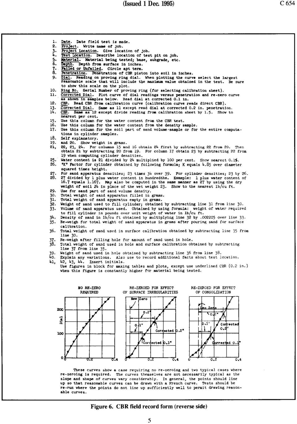
1 (Issued 1 Dec. 1995) C654 CRD-C Standard Test Method for Determining the California Bearing Ratio of Soils* 1. Scope. 1.1 This test method is used for determining the California Bearing Ratio (CBR) of soils either in the field or in the laboratory. 2. Apparatus. 2.1 Cylinder mold. Cylinder mold assembly meeting the requirements indicated in Figure 1. For any group of molds, one extra baseplate is desirable because two plates are required when a mold is inverted during the preparation of the specimen. 2.2 Disk. Disk as shown in Figure Tamper. Compaction tamper as shown in ASTM D Measuring apparatus. Apparatus for measuring expansion of soil, consisting of adjustable stem and perforated plate, tripod, and dial micrometer (reading to in.), as shown in Figure Masses. Masses, including one annular Surcharge mass and several slotted or split surcharge masses as shown in Figure Soaking tank. Soaking tank of sufficient size to accommodate several test molds and of sufficient depth to ensure submergence of the sample. 2.7 Penetration piston. Penetration piston as shown in Figure Loading device. Loading device, either a laboratory testing machine or screwjack and frame arrange Figure 1. California bearing ratio test apparatus * Formerly MIL-STD-62lA. Method 101, 22 December 1964

2 C 654 (Issued 1 Dec. 1995) ment (as illustrated in Figure 2). which can be used to force the penetration piston into the specimen at a uniform rate of 0.05 in. per minute. 5-lb annular disk surcharge weight on the soil surface prior to seating the piston and finally applying the remainder of the weights Seating piston. To seat the penetration piston, bring it into contact with the sample with sufficient pressure to cause the load dial to register a load of between zero and 1 lb Applying loads. Apply loads on the penetration piston so that the rate of penetration is approximately 0.05 in. per minute. Obtain load readings at , , , , , , , and in. deformation. In manually operated loading devices, it may he necessary to take load readings at closer intervals to control the rate of penetration. Figure 2. Laboratory CBR Test equipment 2.9 General laboratory equipment. General laboratory equipment specified in CRD-C Determining moisture content Determine the moisture content in the upper 1 in., and in the case of 2.10 Loading device. Loading device consisting of a mechanical screwjack to apply the load and a loaded truck to provide the resistance for the screwjack (see Figure 3) Proving rings. Calibrated proving rings Penetration piston. Penetration piston, 1.95 in. in diameter, with internally threaded pipe extensions and connectors Micrometers. Dial micrometers and support Steel plate. Steel plate, 10 in. in diameter, having a 2.03-in.-diameter hole in the center and weighing 10 lb. 3. Procedure. 3.1 Penetration test procedure. The following penetration test procedure applies to laboratory and field in-place CBR tests. Satisfactory forms for recording penetration data for laboratory tests and field tests are shown in Figure 4 and Figures 5 and 6, respectively Applying surcharge. Apply sufficient penetration surcharge on the soil being tested to produce an intensity of loading equal to the weight (within ±5 lb) of the base material and pavement that overlie the soil being tested, but the surcharge weight shall be not less than 10 lb. If the sample has been soaked previously, the penetration surcharge must be equal to the soaking surcharge. To prevent upheaval of soil into the hole of the surcharge weights, it is advisable to place one 2 Figure 3. CBR testing equipment

3 (Issued 1 Dec. 1995) C 654 consolidation as a percentage of the initial specimen height Draining specimen. Wipe the free water from the specimen, being careful not to disturb the surface of the specimen; then allow it to drain for 15 minutes. It may be necessary to tilt the specimen in order to achieve good drainage. Figure 4. CBR laboratory record form laboratory tests determine an average moisture content for the entire depth of the sample. 3.2 Procedure for soaking laboratory CBR specimens Placement of masses. Place the adjustable stem and plate on the surface of the sample, and apply an annular mass to produce an intensity of loading equal to within ±5 lb of the mass of the base material and pavement that overlie the soil being tested, but in no case should the surcharge mass be less than 10 lb Placement of tripod. Set tripod on mold and dial stem on adjustable stem from plate and make initial measurement from which to determine swell or consolidation of specimen Soaking specimen. Immerse the mold in water to allow free access of water to top and bottom, and allow the specimen to soak for 4 days. (A shorter soaking period is permissible for soils that take up moisture readily if tests show that a shorter period does not affect the results.) Final measurements. Make final swell or consolidation measurements and calculate the swell or Weighing specimen. Remove the perforated plate and surcharge weights and weigh the specimen. The specimen is now ready for the penetration test. 3.3 General procedure for testing laboratory-compacted CBR specimens Soil grouping for test purposes. For testing laboratory-compacted specimens for the CBR method of design, materials have been grouped into three classes with respect to behavior during saturation: (a) cohesionless sands and gravels, (b) cohesive soils, and (c) highly swelling soils. The first group usually includes the GW, GP, SW, and SP classifications of ASTM D The second group usually includes the GM, GC, SM, SC, ML, CL, and OL classifications. Swelling soils usually comprise the MH, CH, and OH classification. Separate procedures are given for each of the groups Cohesionless sands and gravels. Cohensionless soils usually compact readily under rollers or traffic. Specimens shall be prepared, as specified in CRD- C 653 at high densities and at a range of moisture contents bracketing those anticipated in the field, including moisture contents as high as practicable. If soaking does not lower the CBR, it may be omitted for further tests on the same material Cohesive soils Specimen preparation and compaction curves development. Representative samples of cohesive soils are tested in a manner to develop data that will show their behavior over the entire range of anticipated moisture contents. Test specimens are prepared and compaction curves are developed for the CE 55, CE 26, and CE 12 compaction efforts as described in CRD-C 653. Each specimen shall be soaked and penetrated to develop a complete family of curves showing the relation between density, moisture content, and CBR. To aid in determining the validity of the compaction data, a semilog plot of maximum density versus compaction effort in energy per unit volume usually gives a straight-line relation as illustrated in CRD-C

4 C 654 (Issued 1 Dec. 1995)
")
5 (Issued 1 Dec. 1995)
6 C 654 (Issued 1 Dec. 1995) Obtaining design CBR data. The data from a CBR test are plotted as in Figure 7, and the resulting family of CBR curves represents the characteristics encompassing a wide range of field conditions. The design CBR shall be based on the density and molding moisture content anticipated in the field. For example, assume that the lean clay soil, for which resuits are plotted in Figure 7, can be processed to an average moisture content of 13 percent to 16 percent and that it can be compacted to a density varying from (95 percent of modified maximum density) to 115 Ib/ft 3 (see cross-hatched area on lower left-hand plot of Figure 7). If construction could be controlled so that the density and moisture content were within these ranges, the right-hand plot of Figure 7 indicates that the soils, after moisture conditions had become adjusted, would have a CBR (see cross-hatched area on right-hand lot of Figure 7) varying between about 11 (1105-lb/ft 3 density and 13 percent moisture content) and 26 (1l54lb/ft 3 density and 15 percent moisture content). The design CBR selected should be near the lower value, say 12. The right-hand plot in Figure 7 shows that close control of moisture content within those limits (13 percent to 16 percent) is necessary because low CBR values will be obtained if the moisture content is allowed to increase appreciably above the desired range Swelling soils Test procedures. The test procedures for highly swelling soils are the same as those previously described for cohesive soils; however, the objectives of the testing program are not exactly the same. Tests shall be performed on soils having expansive characteristics to determine a moisture content and a density which will minimize expansion. The proper moisture content and density are not necessarily the optimum moisture content and density for the CE 55 compaction effort. Generally, the minimum swell and highest soaked CBR will occur at a molding moisture content slightly wet of optimum. When testing highly swelling Figure 7. Recommended procedure for performing CBR tests for design 6

7 (Issued 1 Dec. 1995) C 654 soils, it may be necessary to prepare samples for a wider range of moistures and densities than normally used to establish the relation between moisture content, density, swell. and CBR for a given soil. A careful study of the test results will permit the selection of the proper moisture content and density required in the field. It should be noted that the possibility exists that thickness design may be governed by the compaction requirements instead of the CBR in some cases. 3.4 Field in-place tests (see Figures 5 and 6 for data sheet). Field in-place CBR tests are used for design under any one of the following conditions: (a) when the in-place density and water content are such that the degree of saturation (percentage of voids filled with water) is 80 percent or greater; (b) when the material is coarse grained and cohesionless so that it is not affected by changes in water content; and (c) when construction was completed several years before. In the last-named case, the water content does not actually become constant but appears to fluctuate within rather narrow ranges, and the field in-place test is considered a satisfactory indicator of the load-carrying capacity. The time required for the water content to become stabilized cannot be stated definitely, but the minimum time is approximately 3 years Penetration. Level the surface to be tested, and remove all loose material. Then follow the procedure described in Number of tests. Three in-place CBR tests should be performed at each elevation tested in the base course and at the surface of the subgrade. However, if the results of the three tests in any group do not show reasonable agreement, three additional tests should be made at the same location. A reasonable agreement between three tests where the CBR is less than 10 permits a tolerance of 3; where the CBR is less than 10 permits a tolerance of 3; where the CBR is from 10 to 30, a tolerance of 5; and from 30 to 60, a tolerance of 10. For CBR s above 60, variations in the individual readings are not of particular importance. For example, actual test results of 6, 8, and 9 are reasonable and can be averaged as 8; results of 23, 18, and 20 are reasonable and can be averaged as 20. If the first three tests do not fall within the specified tolerance, the three additional tests are made at the same location, and the numerical average of the six tests is used as the CBR at that location Moisture content and density. After completion of the CBR test, a sample shall be obtained (a) at the point of penetration for moisture-content determination, and (b) 4 to 6 in. away from the point of penetration for density determination. 3.5 Undisturbed specimens. Because of the difficulty of obtaining reliable CBR test results on so-called undisturbed specimens, these tests will be performed only in special cases. Note: The past practices of obtaining and testing samples in wooden boxes and of leaving an annular space between sample and container wall to be filled with plastic material such as paraffin shall be discontinued because these practices leave some doubt as to the adequacy of the lateral confinement of specimen during the CBR test. 4. Calculations. 4.1 Calculation procedures. The CBR shall be calculated immediately after completion of the test, as follows Plotting load-penetration curve. Calculate the penetration load in lb/in.* and draw the loadpenetration curve. It is sometimes necessary to correct the CBR value because of surface irregularities and/or the concave-upward shape of the curve that characterizes samples on the wet side of optimum for certain soils. Figure 8 shows both the uncorrected and the corrected CBR curves. Correction can be made graphically by adjusting the zero point of the curve as Figure 8. Correlation of stress-penetration curve

8 C 654 (Issued 1 Dec. 1995) in Figure 8, or it can be made mathematically by selecting the largest CBR value based on load increase divided by the standard loads for any consecutive 0.1- or 0.2-in. penetration. The mathematical correction has the advantage of eliminating the personal error in drawing the corrected curve. However, the curve should be drawn in any case so that erratic data will be more easily recognized Calculating CBR. Determine the corrected load values at 0.1- and 0.2-in. penetration from which the CBR values are obtained by dividing the corrected unit loads at 0.1 and 0.2 in. by the standard loads of 1,000 and 1,500 psi, respectively. Each ratio is multiplied by 100 to obtain the bearing ratio in percent. The CBR is usually selected at 0.1-in. penetration. If the ratio at 0.2-in. penetration is greater, the test should be rerun. If check tests give similar results, use the CBR at 0.2-in. penetration Design CBR value. The specific design CBR values from field test may be determined following procedures indicated in the appropriate flexible pavement design manuals. 8

LABORATORY DETERMINATION OF CALIFORNIA BEARING RATIO
 LABORATORY DETERMINATION OF CALIFORNIA BEARING RATIO STANDARD IS: 2720 (Part 16) 1979. DEFINITION California bearing ratio is the ratio of force per unit area required to penetrate in to a soil mass with
METHOD OF TEST FOR DETERMINATION OF PERMEABILITY OF GRANULAR SOILS
 Laboratory Testing Manual Date: 99 06 21 Page 1 of 7 METHOD OF TEST FOR DETERMINATION OF PERMEABILITY OF GRANULAR SOILS 1. SCOPE 1.1 This method covers the determination of the coefficient of permeability
HIGHWAYS DEPARTMENT GUIDANCE NOTES ON SOIL TEST FOR PAVEMENT DESIGN
 HIGHWAYS DEPARTMENT GUIDANCE NOTES ON SOIL TEST FOR PAVEMENT DESIGN Research & Development Division RD/GN/012 August 1990 HIGHWAYS DEPARTMENT GUIDANCE NOTES (RD/GN/012) SOIL TEST FOR PAVEMENT DESIGN Prepared
A LABORATORY STUDY ON EFFECT OF TEST CONDITIONS ON SUBGRADE STRENGTH
 A LABORATORY STUDY ON EFFECT OF TEST CONDITIONS ON SUBGRADE STRENGTH A REPORT SUBMITTED IN PARTIAL FULFILLMENT OF THE REQUIREMENTS FOR THE DEGREE OF Bachelor of Technology In Civil Engineering By: Rajesh
SOIL-LIME TESTING. Test Procedure for. TxDOT Designation: Tex-121-E 1. SCOPE 2. APPARATUS 3. MATERIALS TXDOT DESIGNATION: TEX-121-E
 Test Procedure for SOIL-LIME TESTING TxDOT Designation: Tex-121-E Effective Date: August 2002 1. SCOPE 1.1 This method consists of three parts. 1.1.1 Part I determines the unconfined compressive strength
c. Borehole Shear Test (BST): BST is performed according to the instructions published by Handy Geotechnical Instruments, Inc.
: BST is performed according to the instructions published by Handy Geotechnical Instruments, Inc.") Design Manual Chapter 6 - Geotechnical 6B - Subsurface Exploration Program 6B-2 Testing A. General Information Several testing methods can be used to measure soil engineering properties. The advantages,
Design Manual Chapter 6 - Geotechnical 6B - Subsurface Exploration Program 6B-2 Testing A. General Information Several testing methods can be used to measure soil engineering properties. The advantages,
Soil Testing 24 Compaction and CBR. Compaction Test 4.5 kg BS 1377-4, 1924-2, EN DD ENV 1997-2
 24 Compaction and CBR Dry Density/Moisture Relationship BS/EN DD ENV Compaction Test 2.5 kg BS 1377-4, 1924-2, EN DD ENV 1997-2 This test method utilises a 2.5 kg hand compaction hammer and a one litre
COMPENDIUM OF INDIAN STANDARDS ON SOIL ENGINEERING PART 2
 (PREVIEW) SP 36 (Part 2) : 1988 COMPENDIUM OF INDIAN STANDARDS ON SOIL ENGINEERING PART 2 IS 1893 : 1979 (Reaffirmed 1987) CODE OF PRACTICE FOR SUBSURFACE INVESTIGATION FOR FOUNDATIONS 1.1 This code deals
PERMEABILITY TEST. To determine the coefficient of permeability of a soil using constant head method.
 PERMEABILITY TEST A. CONSTANT HEAD OBJECTIVE To determine the coefficient of permeability of a soil using constant head method. need and Scope The knowledge of this property is much useful in solving problems
CEEN 162 - Geotechnical Engineering Laboratory Session 7 - Direct Shear and Unconfined Compression Tests
 PURPOSE: The parameters of the shear strength relationship provide a means of evaluating the load carrying capacity of soils, stability of slopes, and pile capacity. The direct shear test is one of the
SECTION 31 20 00 EARTH MOVING
 SECTION 31 20 00 PART 1 - GENERAL 1.01 DESCRIPTION A. This Section describes the requirements for excavating, filling, and grading for earthwork at Parking Structure, new exit stair and as required to
LABORATORY CLASSIFICATION OF SOILS FOR ENGINEERING PURPOSES
 Test Procedure for LABORATORY CLASSIFICATION OF SOILS FOR ENGINEERING PURPOSES TxDOT Designation: Tex-142-E Effective Date: August 1999 1. SCOPE 1.1 This method is a system for classifying disturbed and
Specification Guidelines: Allan Block Modular Retaining Wall Systems
 Specification Guidelines: Allan Block Modular Retaining Wall Systems The following specifications provide Allan Block Corporation's typical requirements and recommendations. At the engineer of record's
METHOD A10 (a) THE DETERMINATION OF THE IN-PLACE DRY DENSITY OF SOIL OR GRAVEL BY THE SAND REPLACEMENT METHOD
 THE DETERMINATION OF THE IN-PLACE DRY DENSITY OF SOIL OR GRAVEL BY THE SAND REPLACEMENT METHOD") METHOD A10 (a) THE DETERMINATION OF THE IN-PLACE DRY DENSITY OF SOIL OR GRAVEL BY THE SAND REPLACEMENT METHOD 1 SCOPE The in-place dry density of compacted soil or gravel, as defined below, is determined
METHOD A10 (a) THE DETERMINATION OF THE IN-PLACE DRY DENSITY OF SOIL OR GRAVEL BY THE SAND REPLACEMENT METHOD 1 SCOPE The in-place dry density of compacted soil or gravel, as defined below, is determined
DIRECT SHEAR TEST SOIL MECHANICS SOIL MECHANICS LABORATORY DEPARTMENT OF CIVIL ENGINEERING UNIVERSITY OF MORATUWA SRI LANKA
 DIRECT SHEAR TEST SOIL MECHANICS SOIL MECHANICS LABORATORY DEPARTMENT OF CIVIL ENGINEERING UNIVERSITY OF MORATUWA SRI LANKA DIRECT SHEAR TEST OBJEVTIVES To determine the shear strength parameters for a
C. Section 014510 TESTING LABORATORY SERVICE.
 SECTION 014500 QUALITY CONTROL PART 1 GENERAL 1.01 RELATED REQUIREMENTS A. Drawings and General Provisions of Contract, including General and Special Conditions and other Division 1 Specification Sections,
METHOD A7 THE DETERMINATION OF THE MAXIMUM DRY DENSITY AND OPTIMUM MOISTURE CONTENT OF GRAVEL, SOIL AND SAND
 SCOPE METHOD A7 THE DETERMINATION OF THE MAXIMUM DRY DENSITY AND OPTIMUM MOISTURE CONTENT OF GRAVEL, SOIL AND SAND Definition The maximum dry density and optimum moisture content, as defined below, is
CONSTANT HEAD AND FALLING HEAD PERMEABILITY TEST
 CONSTANT HEAD AND FALLING HEAD PERMEABILITY TEST 1 Permeability is a measure of the ease in which water can flow through a soil volume. It is one of the most important geotechnical parameters. However,
The Verdura Wall check with your local building department
 The Verdura Wall The Verdura Wall by Soil Retention Products, Inc of Carlsbad, California can be constructed as a gravity retaining structure or a geosynthetic reinforced segmental retaining wall, depending
Effect of grain size, gradation and relative density on shear strength and dynamic cone penetration index of Mahi, Sabarmati and Vatrak Sand
 Discovery ANALYSIS The International Daily journal ISSN 2278 5469 EISSN 2278 5450 2015 Discovery Publication. All Rights Reserved Effect of grain size, gradation and relative density on shear strength
SPECIFICATIONS FOR PRECAST MODULAR BLOCK RETAINING WALL SYSTEM (revised 11/5/13)
") Page 1 of 7 STONE STRONG SYSTEMS SPECIFICATIONS FOR PRECAST MODULAR BLOCK RETAINING WALL SYSTEM (revised ) PART 1: GENERAL 1.01 Description A. Work includes furnishing and installing precast modular blocks
Page 1 of 7 STONE STRONG SYSTEMS SPECIFICATIONS FOR PRECAST MODULAR BLOCK RETAINING WALL SYSTEM (revised ) PART 1: GENERAL 1.01 Description A. Work includes furnishing and installing precast modular blocks
GRADATION OF AGGREGATE FOR CONCRETE BLOCK
 GRADATION OF AGGREGATE FOR CONCRETE BLOCK Although numerous papers have been written concerning the proper gradation for concrete mixes, they have generally dealt with plastic mixes, and very little published
SPECIFICATION FOR DYNAMIC CONSOLIDATION / DYNAMIC REPLACEMENT
 SPECIFICATION FOR DYNAMIC CONSOLIDATION / DYNAMIC REPLACEMENT 1.0 SOIL IMPROVEMENT 1.1 General Soil Investigation Information are provided in Part B1 annex as a guide to the Contractor for his consideration
Commonwealth of Pennsylvania PA Test Method No. 632 Department of Transportation October 2013 5 Pages LABORATORY TESTING SECTION. Method of Test for
 Commonwealth of Pennsylvania PA Test Method No. 632 Department of Transportation 5 Pages LABORATORY TESTING SECTION Method of Test for TIME OF SETTING OF CONCRETE MIXTURES BY PENETRATION RESISTANCE 1.
Measurement of Soil Parameters by Using Penetrometer Needle Apparatus
 Vol.3, Issue.1, Jan-Feb. 2013 pp-284-290 ISSN: 2249-6645 Measurement of Soil Parameters by Using Penetrometer Needle Apparatus Mahmoud M. Abu zeid, 1 Amr M. Radwan, 2 Emad A. Osman, 3 Ahmed M.Abu-bakr,
GUIDELINE FOR HAND HELD SHEAR VANE TEST
 GUIDELINE FOR HAND HELD SHEAR VANE TEST NZ GEOTECHNICAL SOCIETY INC August 2001 CONTENTS Page 1.0 Introduction 2 2.0 Background 2 3.0 Recommended Practice 3 4.0 Undrained Shear Strength 3 5.0 Particular
SECTION 32 14 13.19 PERMEABLE INTERLOCKING CONCRETE PAVEMENT (1995 MasterFormat Section 02795)
") SECTION 32 14 13.19 PERMEABLE INTERLOCKING CONCRETE PAVEMENT (1995 MasterFormat Section 02795) Note: This guide specification for U.S. applications describes construction of permeable interlocking concrete
SECTION 32 14 13.19 PERMEABLE INTERLOCKING CONCRETE PAVEMENT (1995 MasterFormat Section 02795) Note: This guide specification for U.S. applications describes construction of permeable interlocking concrete
4-02 Gravel Base. 4-04 Ballast and Crushed Surfacing
 Chapter 4 Bases 4-02 Gravel Base GEN 4-02.1 General Instructions Gravel Base is typically used in the construction of the roadway section and provides support for the pavement. For the pavement to provide
DIVISION 300 BASES SECTION 304 AGGREGATE BASE COURSE DESCRIPTION MATERIALS CONSTRUCTION REQUIREMENTS
 304.06 DIVISION 300 BASES SECTION 304 AGGREGATE BASE COURSE DESCRIPTION 304.01 This work consists of furnishing and placing one or more courses of aggregate and additives, if required, on a prepared subgrade.
GEOTECHNICAL ENGINEERING FORMULAS. A handy reference for use in geotechnical analysis and design
 GEOTECHNICAL ENGINEERING FORMULAS A handy reference for use in geotechnical analysis and design TABLE OF CONTENTS Page 1. SOIL CLASSIFICATION...3 1.1 USCS: Unified Soil Classification System...3 1.1.1
INTRODUCTION TO SOIL MODULI. Jean-Louis BRIAUD 1
 INTRODUCTION TO SOIL MODULI By Jean-Louis BRIAUD 1 The modulus of a soil is one of the most difficult soil parameters to estimate because it depends on so many factors. Therefore when one says for example:
NOTE: FOR PROJECTS REQUIRING CONTRACTOR MIX DESIGN, THE DESIGN PROCEDURES ARE SPECIFIED IN THE SPECIAL PROVISIONS OF THE CONTRACT.
 September 1, 2003 CONCRETE MANUAL 5-694.300 MIX DESIGN 5-694.300 NOTE: FOR PROJECTS REQUIRING CONTRACTOR MIX DESIGN, THE DESIGN PROCEDURES ARE SPECIFIED IN THE SPECIAL PROVISIONS OF THE CONTRACT. 5-694.301
PART I SIEVE ANALYSIS OF MATERIAL RETAINED ON THE 425 M (NO. 40) SIEVE
 SIEVE") Test Procedure for PARTICLE SIZE ANALYSIS OF SOILS TxDOT Designation: Tex-110-E Effective Date: August 1999 1. SCOPE 1.1 This method covers the quantitative determination of the distribution of particle
Test Procedure for PARTICLE SIZE ANALYSIS OF SOILS TxDOT Designation: Tex-110-E Effective Date: August 1999 1. SCOPE 1.1 This method covers the quantitative determination of the distribution of particle
KWANG SING ENGINEERING PTE LTD
 KWANG SING ENGINEERING PTE LTD 1. INTRODUCTION This report represents the soil investigation works at Aljunied Road / Geylang East Central. The objective of the soil investigation is to obtain soil parameters
SOIL COMPACTION BASICS
 SOIL COMPACTION BASICS Figure courtesy of : A Basic Handbook by MultiQuip. : Densification of soil by the removal of air. Courtesy of http://www.extension.umn.edu Slide 1 of 38 WHY COMPACT SOILS? Figure
PHYSICAL AND PLASTICITY CHARACTERISTICS
 0 PHYSICAL AND PLASTICITY CHARACTERISTICS EXPERIMENTS #1-5 CE 3143 October 7, 2003 Group A David Bennett 1 TABLE OF CONTENTS 1. Experiment # 1: Determination of Water Content (August 26, 2003) pp. 1-3
Apr 17, 2000 LAB MANUAL 1811.0
 Apr 17, 2000 LAB MANUAL 1811.0 1811 BULK SPECIFIC GRAVITY (GMB) AND DENSITY OF COMPACTED BITUMINOUS SPECIMENS USING PARAFFIN OR PARAFILM ASTM Designation D 1188 (MN/DOT Modified) 1811.1 SCOPE This test
SECTION 3.3 - PAVEMENT DESIGN
 SECTION 3.3-3.3.1 GENERAL 3.3.2 SUBSURFACE DRAINAGE 3.3.3 DETERMINATION OF DESIGN TRAFFIC 3.3.4 SUBGRADE EVALUATION 3.3.5 PAVEMENT THICKNESS 3.3.5.1 GRANULAR PAVEMENTS WITH THIN BITUMINOUS SURFACING 3.3.5.2
A study on the Effect of Distorted Sampler Shoe on Standard Penetration Test Result in Cohesionless soil
 ISSN: 319-53 (An ISO 39: 00 Certified Organization) A study on the Effect of Distorted Sampler Shoe on Standard Penetration Test Result in Cohesionless soil Utpal Kumar Das Associate Professor, Department
Apr 17, 2000 LAB MANUAL 1302.0. 1302 PARTICLE SIZE ANALYSIS OF SOILS AASHTO Designation T 88 (Mn/DOT Modified)
") Apr 17, 2000 LAB MANUAL 1302.0 1302 PARTICLE SIZE ANALYSIS OF SOILS AASHTO Designation T 88 (Mn/DOT Modified) 1302.1 SCOPE This method describes a procedure for the quantitative determination of the distribution
Apr 17, 2000 LAB MANUAL 1302.0 1302 PARTICLE SIZE ANALYSIS OF SOILS AASHTO Designation T 88 (Mn/DOT Modified) 1302.1 SCOPE This method describes a procedure for the quantitative determination of the distribution
SECTION 32 14 13.19 PERMEABLE INTERLOCKING CONCRETE PAVEMENT (1995 MasterFormat Section 02795)
") SECTION 32 14 13.19 PERMEABLE INTERLOCKING CONCRETE PAVEMENT (1995 MasterFormat Section 02795) Note: This guide specification for U.S. applications describes construction of permeable interlocking concrete
SECTION 32 14 13.19 PERMEABLE INTERLOCKING CONCRETE PAVEMENT (1995 MasterFormat Section 02795) Note: This guide specification for U.S. applications describes construction of permeable interlocking concrete
Comparison of the Humboldt GeoGauge With In-Place Quasi-Static Plate Load Tests. Charles R. Nelson, P.E. Mike Sondag
 Comparison of the Humboldt GeoGauge With In-Place Quasi-Static Plate Load Tests Charles R. Nelson, P.E. Mike Sondag CNA Consulting Engineers 2800 University Ave. S.E. Minneapolis, MN 55414 December, 1999
Standard Test Procedures Manual
 STP 240-6 Standard Test Procedures Manual Section: PENETRATION TEST & SPLIT- BARREL SAMPLING 1. SCOPE 1.1. Description of Test This method describes the standard penetration test using the split-barrel
The University of Toledo Soil Mechanics Laboratory
 The University of Toledo Soil Mechanics Laboratory 1 Soil Moisture-Density Relationship Standard and Modified Proctor Tests Introduction For earthork construction it is important to compact soils to a
product manual HS-4210 HS-4210_MAN_09.08 Digital Static Cone Penetrometer
 HS-4210_MAN_09.08 product manual HS-4210 Digital Static Cone Penetrometer Introduction This Manual covers the measurement of bearing capacity using the Humboldt Digital Static Cone Penetrometer (DSCP).
Standard Practice for Classification of Soils for Engineering Purposes (Unified Soil Classification System) 1
 1") Designation: D 2487 06 Standard Practice for Classification of Soils for Engineering Purposes (Unified Soil Classification System) 1 This standard is issued under the fixed designation D 2487; the number
Designation: D 2487 06 Standard Practice for Classification of Soils for Engineering Purposes (Unified Soil Classification System) 1 This standard is issued under the fixed designation D 2487; the number
14.330 SOIL MECHANICS Assignment #4: Soil Permeability.
 Geotechnical Engineering Research Laboratory One University Avenue Lowell, Massachusetts 01854 Edward L. Hajduk, D.Eng, PE Lecturer PA105D Tel: (978) 94 2621 Fax: (978) 94 052 e mail: Edward_Hajduk@uml.edu
CIVL451. Soil Exploration and Characterization
 CIVL451 Soil Exploration and Characterization 1 Definition The process of determining the layers of natural soil deposits that will underlie a proposed structure and their physical properties is generally
INSITU TESTS! Shear Vanes! Shear Vanes! Shear Vane Test! Sensitive Soils! Insitu testing is used for two reasons:!
 In-situ Testing! Insitu Testing! Insitu testing is used for two reasons:! To allow the determination of shear strength or penetration resistance or permeability of soils that would be difficult or impossible
Division 2 Section 32 14 13.19 Section 02795
 Note: The text must be edited to suit specific project requirements. It should be reviewed by a qualified civil or geotechnical engineer, or landscape architect familiar with the site conditions. Edit
SECTION 311 PLACEMENT AND CONSTRUCTION OF CEMENT TREATED SUBGRADESOIL CEMENT BASE COURSE
 PLACEMENT AND CONSTRUCTION OF CEMENT TREATED SUBGRADESOIL CEMENT BASE COURSE 311.1 DESCRIPTION: This item shall consist of a cement treated subgrade base course composed of a mixture of local soil, portland
Designed and Engineered to Perform
 History EARTH CONTACT PRODUCTS, L.L.C., is a family owned company, based in Olathe, Kansas. This company was built upon Don May s U.S. Patented fourth-generation Steel Piering System that has led to the
PILE FOUNDATIONS FM 5-134
 C H A P T E R 6 PILE FOUNDATIONS Section I. GROUP BEHAVIOR 6-1. Group action. Piles are most effective when combined in groups or clusters. Combining piles in a group complicates analysis since the characteristics
Pavement Thickness. esign and RCC-Pave Software. Roller-Compacted Concrete Pavement: Design and Construction. October 24, 2006 Atlanta, Georgia
 Roller-Compacted Concrete Pavement: Design and Construction Pavement Thickness esign and RCC-Pave Software Gregory E. Halsted, P.E. Pavements Engineer Portland Cement Association October 24, 2006 Atlanta,
The AASHO Road Test site (which eventually became part of I-80) at Ottawa, Illinois, was typical of northern climates (see Table 1).
 at Ottawa, Illinois, was typical of northern climates (see Table 1).") Página 1 de 12 AASHO Road Test The AASHO Road Test, a $27 million (1960 dollars) investment and the largest road experiment of its time, was conceived and sponsored by the American Association of State
Página 1 de 12 AASHO Road Test The AASHO Road Test, a $27 million (1960 dollars) investment and the largest road experiment of its time, was conceived and sponsored by the American Association of State
REINFORCED CONCRETE. Reinforced Concrete Design. A Fundamental Approach - Fifth Edition. Walls are generally used to provide lateral support for:
 HANDOUT REINFORCED CONCRETE Reinforced Concrete Design A Fundamental Approach - Fifth Edition RETAINING WALLS Fifth Edition A. J. Clark School of Engineering Department of Civil and Environmental Engineering
SAMPLE GUIDE SPECIFICATIONS FOR OSTERBERG CELL LOAD TESTING OF DEEP FOUNDATIONS
 Page 1 of 9 SAMPLE GUIDE SPECIFICATIONS FOR OSTERBERG CELL LOAD TESTING OF DEEP FOUNDATIONS 1. GENERAL REQUIREMENTS 1. Description of Work: This work consists of furnishing all materials, equipment and
SECTION 02795 UNI PERMEABLE INTERLOCKING CONCRETE PAVEMENT
 SECTION 02795 UNI PERMEABLE INTERLOCKING CONCRETE PAVEMENT Note: This guide specification is intended for use in the U.S. It describes construction of permeable interlocking concrete pavers on a permeable,
SECTION 623 CONCRETE BONDING COMPOUND, EPOXY MORTAR AND EPOXY POLYMER CONCRETE OVERLAY SECTION 623.10 CONCRETE BONDING COMPOUND.
 SECTION 623 CONCRETE BONDING COMPOUND, EPOXY MORTAR AND EPOXY POLYMER CONCRETE OVERLAY SECTION 623.10 CONCRETE BONDING COMPOUND. 623.10.1 Description. This work shall consist of preparing the surface,
Module 1 : Site Exploration and Geotechnical Investigation. Lecture 4 : In-situ tests [ Section 4.1: Penetrometer Tests ] Objectives
![Module 1 : Site Exploration and Geotechnical Investigation. Lecture 4 : In-situ tests [ Section 4.1: Penetrometer Tests ] Objectives](/thumbs/26/8734290.jpg "Module 1 : Site Exploration and Geotechnical Investigation. Lecture 4 : In-situ tests [ Section 4.1: Penetrometer Tests ] Objectives") Lecture 4 : In-situ tests [ Section 4.1: Penetrometer Tests ] Objectives In this section you will learn the following Penetrometer Tests Standard penetration test Static cone penetration test Dynamic cone
Lecture 4 : In-situ tests [ Section 4.1: Penetrometer Tests ] Objectives In this section you will learn the following Penetrometer Tests Standard penetration test Static cone penetration test Dynamic cone
ENCE 4610 Foundation Analysis and Design
 This image cannot currently be displayed. ENCE 4610 Foundation Analysis and Design Shallow Foundations Total and Differential Settlement Schmertmann s Method This image cannot currently be displayed. Strength
Evaluation of Properties of Soil Subgrade Using Dynamic Cone Penetration Index A Case Study
 International Journal of Engineering Research and Development e-issn: 2278-067X, p-issn: 2278-800X Volume 4, Issue 4 (October 202), PP. 07-5 Evaluation of Properties of Soil Subgrade Using Dynamic Cone
1. ASTM C 140 - Sampling and Testing Concrete Masonry Units 2. ASTM C 1372 Standard Specification for Dry-Cast Segmental Retaining Wall Units
 SPECIFICATION FOR SEGMENTAL RETAINING WALL SYSTEMS PART 1: GENERAL 1.01 Description A. Work shall consist of furnishing materials, labor, equipment and supervision to install a segmental retaining wall
How To Design A Foundation
 The Islamic university - Gaza Faculty of Engineering Civil Engineering Department CHAPTER (2) SITE INVESTIGATION Instructor : Dr. Jehad Hamad Definition The process of determining the layers of natural
Soil Mechanics. Soil Mechanics
 Soil is the most misunderstood term in the field. The problem arises in the reasons for which different groups or professions study soils. Soil scientists are interested in soils as a medium for plant
FUNDAMENTALS OF CONSOLIDATION
 FUNDAMENTALS OF CONSOLIDATION SAND (Vertical Stress Increase) CLAY CONSOLIDATION: Volume change in saturated soils caused by the expulsion of pore water from loading. Saturated Soils: causes u to increase
Installation PowerPoint for Grasscrete Formers
 Installation PowerPoint for Grasscrete Formers 1 This document describes the two single-use tools utilized to create the Grasscrete product. The original Former is a vacuum formed light gauge plastic mold
PERMEABLE INTERLOCKING CONCRETE PAVEMENT
 [NOTE TO SPECIFICATION WRITER: This guide specification for the use of permeable interlocking concrete pavers for pedestrian and vehicular traffic application was developed based on the use of an open-graded
Trench Rescue by Buddy Martinette
 Trench Rescue by Buddy Martinette SOIL TYPE AND TESTING It is imperative that rescue personnel understand soil types and testing procedures if the want to be competent at trench rescue operations. Determining
Geotechnical Measurements and Explorations Prof. Nihar Ranjan Patra Department of Civil Engineering Indian Institute of Technology, Kanpur
 Geotechnical Measurements and Explorations Prof. Nihar Ranjan Patra Department of Civil Engineering Indian Institute of Technology, Kanpur Lecture No. # 28 Last lecture we have covered this Atterberg limit,
NJ650.1404 Interception Drainage
 NJ650.1404 Interception Drainage Interception drainage is used to intercept surface and subsurface water. The investigation, planning, and construction of surface interception drains follow the requirements
SECTION 32 14 13.19 PERMEABLE INTERLOCKING CONCRETE PAVEMENT
 PART 1 GENERAL 1.1 SECTION INCLUDES SECTION 32 14 13.19 PERMEABLE INTERLOCKING CONCRETE PAVEMENT A. The requirements for construction of permeable interlocking concrete pavement: 1. Install the interlocking
State of Illinois Department Of Transportation CONSTRUCTION INSPECTOR S CHECKLIST FOR STORM SEWERS
 State of Illinois Department Of Transportation CONSTRUCTION INSPECTOR S CHECKLIST FOR STORM SEWERS While its use is not required, this checklist has been prepared to provide the field inspector a summary
SECTION 55 PIPE FOR STORM DRAINS AND CULVERTS (FAA D-701)
") SECTION 55 PIPE FOR STORM DRAINS AND CULVERTS (FAA D-701) 55-1 GENERAL The Contractor shall perform all work required by the plans for construction of pipe for storm drains, precast polymer trench drains
SECTION 55 PIPE FOR STORM DRAINS AND CULVERTS (FAA D-701) 55-1 GENERAL The Contractor shall perform all work required by the plans for construction of pipe for storm drains, precast polymer trench drains
COMPACTING BITUMINOUS SPECIMENS USING THE SUPERPAVE GYRATORY COMPACTOR (SGC)
") Test Procedure for COMPACTING BITUMINOUS SPECIMENS USING THE SUPERPAVE TxDOT Designation: Tex-241-F Effective Date: December 2015 1. SCOPE 1.1 Use this test method to: compact cylindrical specimens of
Test Procedure for COMPACTING BITUMINOUS SPECIMENS USING THE SUPERPAVE TxDOT Designation: Tex-241-F Effective Date: December 2015 1. SCOPE 1.1 Use this test method to: compact cylindrical specimens of
SECTION 1 GENERAL REQUIREMENTS
 Page 1 of 6 SECTION 1 GENERAL REQUIREMENTS 1. SCOPE OF WORK: The work to be performed under the provisions of these documents and the contract based thereon includes furnishing all labor, equipment, materials,
Drained and Undrained Conditions. Undrained and Drained Shear Strength
 Drained and Undrained Conditions Undrained and Drained Shear Strength Lecture No. October, 00 Drained condition occurs when there is no change in pore water pressure due to external loading. In a drained
Standard Test Procedures Manual
 STP 206-4 Standard Test Procedures Manual Section: 1. SCOPE 1.1. Description of Test This method describes the procedure for determining the liquid limit, plastic limit and the plasticity index of coarse-grained
Testing Procedures. Note: Please refer to Table 2 for a list of completed borings.
 Testing Procedures Drilling and Sampling: Standard penetration tests (SPT) were conducted for every ten feet of boring advancement. SPT tests were conducted in accordance with ASTM D1586, using a 140 pound
THE DETERMINATION OF THE MAXIMUM DRY DENSITY AND OPTIMUM MOISTURE CONTENT OF MATERIALS USING THE VIBRATORY HAMMER COMPACTION
 THE DETERMINATION OF THE MAXIMUM DRY DENSITY AND OPTIMUM MOISTURE CONTENT OF MATERIALS USING THE VIBRATORY HAMMER COMPACTION 1. SCOPE The maximum dry density and optimum moisture content, as defined below,
In-situ Density Determination by Sand Replacement Method
 University of Texas at Arlington Geotechnical Engineering Laboratory Test Procedure In-situ Density Determination by Sand Replacement Method Lecture Note 7 (Thursday 03-04-04) 1 Definitions, Objectives
Lab 1 Concrete Proportioning, Mixing, and Testing
 Lab 1 Concrete Proportioning, Mixing, and Testing Supplemental Lab manual Objectives Concepts Background Experimental Procedure Report Requirements Discussion Prepared By Mutlu Ozer Objectives Students
load on the soil. For this article s examples, load bearing values given by the following table will be assumed.
 How Many Piers? By Gary Collins, P.E. A clear-cut guide to helical pier spacing Introduction Helical pier spacing is not an exact science. How many does it take to support a structure adequately or repair
Quality control: Annex-A.
 Quality control: Quality of the constructed work has been checked by our staff as per frequency and provision mentioned section 900 in MoRT&H and as per provision mentioned in Concession Agreement. The
Seven. Easy Steps. Your Own Walkway, Without Mortar. or Concrete. to Installing. Driveway and Patio
 Seven Easy Steps to Installing Your Own Walkway, Driveway and Patio Without Mortar or Concrete Brick is one of the world s oldest and most enduring building materials. Those same qualities also make it
Proper use of the Rebound Hammer Updated to reflect the changes to ASTM C805
 CEMEX USA - Technical Bulletin 2.1 Proper use of the Rebound Hammer Updated to reflect the changes to ASTM C805 The Rebound Hammer has been around since the late 1940 s and today is a commonly used method
Chapter 8 Design of Concrete Mixes
 Chapter 8 Design of Concrete Mixes 1 The basic procedure for mix design is applicable to concrete for most purposes including pavements. Concrete mixes should meet; Workability (slump/vebe) Compressive
ALLOWABLE LOADS ON A SINGLE PILE
 C H A P T E R 5 ALLOWABLE LOADS ON A SINGLE PILE Section I. BASICS 5-1. Considerations. For safe, economical pile foundations in military construction, it is necessary to determine the allowable load capacity
TECHNICAL REPORT ON SCALA DYNAMIC CONE PENETROMETER IRREGULARITY
 TECHNICAL REPORT ON SCALA DYNAMIC CONE PENETROMETER IRREGULARITY CETANZ Technical Report TR 1 Author(s) SJ Anderson, Geotechnics Ltd Report Date First Issue May 2010 Report Revision Date September 2011
SECTION 02720 SANITARY SEWER AND STORM DRAIN SYSTEMS
 SECTION 02720 SANITARY SEWER AND STORM DRAIN SYSTEMS PART 1 GENERAL 1.01 SECTION INCLUDES A. The requirements for pipe material and installation in sewer and drainage collection systems. All materials
Specific Task Training Program Course S-33 Soils Field Testing and Inspection: Course Reference Manual
 Specific Task Training Program Course S-33 Soils Field Testing and Inspection: Course Reference Manual Specific Task Training Program Course S 33 Soils Field Testing and Inspection Course Reference Manual
research report Investigation of Proposed AASHTO Rut Test Procedure Using the Asphalt Pavement Analyzer Virginia Transportation Research Council
 Final Report VTRC 07-R11 Virginia Transportation Research Council research report Investigation of Proposed AASHTO Rut Test Procedure Using the Asphalt Pavement Analyzer http:/www.virginiadot.org/vtrc/main/online_reports/pdf/07-r11.pdf
Bethel Township Municipal Authority (BTMA) RESIDENTIAL SEWER CONNECTION MANUAL
 RESIDENTIAL SEWER CONNECTION MANUAL") 155 E. Front Street (rear) Lititz, PA 17543 Phone (717) 625-1930 Fax (717) 625-1931 Bethel Township Municipal Authority (BTMA) RESIDENTIAL SEWER CONNECTION MANUAL CONSTRUCTION SPECIFICATIONS AND DETAILS
155 E. Front Street (rear) Lititz, PA 17543 Phone (717) 625-1930 Fax (717) 625-1931 Bethel Township Municipal Authority (BTMA) RESIDENTIAL SEWER CONNECTION MANUAL CONSTRUCTION SPECIFICATIONS AND DETAILS
Civil. 2. City of Seattle Supplement to the Specification for Road, Bridge and Municipal Construction, most current addition.
 Design Guide Basis of Design This section applies to the design and installation of earthwork and backfill. Design Criteria No stockpiling of excavation materials is allowed unless the Geotechnical Engineer
INTERNATIONAL JOURNAL OF CIVIL AND STRUCTURAL ENGINEERING Volume 3, No 3, 2013
 INTERNATIONAL JOURNAL OF CIVIL AND STRUCTURAL ENGINEERING Volume 3, No 3, 2013 Copyright by the authors - Licensee IPA- Under Creative Commons license 3.0 Research article ISSN 0976 4399 Reliability of
CHAPTER: 6 FLOW OF WATER THROUGH SOILS
 CHAPTER: 6 FLOW OF WATER THROUGH SOILS CONTENTS: Introduction, hydraulic head and water flow, Darcy s equation, laboratory determination of coefficient of permeability, field determination of coefficient
1 Mobilisation and demobilisation 1 Deep boring sum 2 Cone penetration tests sum 3 Miscellenous tests sum
 Malaysian Civil Engineering Standard Method of Measurement (MyCESMM) CLASS D: SITE INVESTIGATION WORK Measurement covered under other classes: Excavation not carried out for the purpose of soil investigation
Ohio Department of Transportation Division of Production Management Office of Geotechnical Engineering. Geotechnical Bulletin PLAN SUBGRADES
 Ohio Department of Transportation Division of Production Management Office of Geotechnical Engineering Geotechnical Bulletin GB 1 PLAN SUBGRADES Geotechnical Bulletin GB1 was jointly developed by the Offices
EXPERIMENT 10 CONSTANT HEAD METHOD
 EXPERIMENT 10 PERMEABILITY (HYDRAULIC CONDUCTIVITY) TEST CONSTANT HEAD METHOD 106 Purpose: The purpose of this test is to determine the permeability (hydraulic conductivity) of a sandy soil by the constant
July 2005 Technical Memorandum: UCPRC-TM-2005-12. Authors: D. Jones and J. Harvey PREPARED FOR: PREPARED BY:
 July 2005 Technical Memorandum: UCPRCTM200512 Relationship Between DCP, Stiffness, Shear Strength and RValue Authors: D. Jones and J. Harvey Partnered Pavement Research Program (PPRC) Contract Strategic