ENGINE COOLING SYSTEM
|
|
|
- Merry Fields
- 7 years ago
- Views:
Transcription
1 ENGINE COOLING SYSTEM 3.1 Necessity for cooling In an internal combustion engine, the fuel is burned within the engine cylinder. During combustion, high temperatures are reached within the cylinder, for example in a compression ignition engine as high as C is reached. About one third of the heat energy liberated b the burning fuel is converted into power. Another one third goes out through the exhaust pipe unused. The remaining one third flows into the various components of the engine, namely, cylinder, cylinder head, valves, spark plug (in SI engines), fuel injector (in CI engines) and pistons. This heat flow takes place during combustion and expansion processes. 3.2 Effects of over heating of the engine components: 1. Evaporation of lubricating oil that lubricates the piston and cylinder wall. This will result in metal to metal contact of the piston and cylinder wall leading to piston scuffing and piston seizure. 2. Setting up of thermal stresses in the cylinder, cylinder head and piston. This may lead to cracking of them. 3. Sticking of piston rings in the ring grooves, due to carbonization of the oil. Ring sticking will result in inefficient sealing of the cylinder, increased blow by of gases and loss of thermal efficiency. 4. Burning of piston crown. 5. Burning and warping of exhaust valves. 6. Reduction in volumetric efficient i.e. reduced weight of charge retained in the cylinder.
, fuel injector (in CI engines) and pistons.")
2 3.3 Optimum cooling To avoid overheating, and the consequent ill effects mentioned above, the heat transferred to an engine component (after a certain level) must be removed as quickly as possible and be conveyed to the atmosphere. It will be proper to say the cooling system as a temperature regulation system. It should be remembered that abstraction of heat from the working medium by way of cooling the engine components is a direct thermodynamic loss. Effects of excessive cooling: 1. Reduction in thermal efficiency. 2. Increased corrosion of engine parts. 3. Reduced mechanical efficiency. 4. Improper vaporization of fuel. Hence, if high thermal efficiency is desired the quantity of heat abstracted shall not be more than that necessary to prevent overheating. 3.4 Air cooling In air cooling, large quantities of air is circulated around the hot engine components. In two wheeler engines, air flows over the engine components due to the movement of the vehicles. In other types, where the engine is totally enclosed by the vehicle body, air is forced by a fan or blower of generous capacity. The fan or blower is fixed to the flywheel.

3 The air is delivered through the ducts and is directed along the spaces between the fins. Typical blower cooling system of an inline engine can be seen in figure below. Baffles or cowling surround the cylinder and direct air well over the cylinders and thereby improve cooling.

4 3.5 Advantages of air cooling: 1. Cylinder and cylinder head casting are less complicated. 2. Engine weight is reduced, because engine jackets are not there. 3. Cheaper to manufacture- both labor and material. 4. Volume or size (overall) may be reduced, as no device such as radiator is required for re-cooling the coolant. 5. Engine warms up more quickly, and delivers its full power in lesser time than the liquid cooled engines. 6. Quick starting of the engine is possible even in frosty weather. 7. Rate of coolant frost (ice) damage of the engine (jackets) is not there.

5 8. Risk of coolant frost (ice) damage of the engine (jackets) is not there. 9. Engine is less liable to break down. Radiator unit and joints tubing and other sources of coolant leakage. Disadvantages of air cooling: 1. Greater mechanical noise, particularly because of the fan. 2. Not suitable for multi-cylinder engines, unless a fan (which absorbs some power) and suitable cowling are used. 3. Not suitable for engines to be mounted on vehicles meant for agricultural and construction applications. This is because the space between the cooling fins are likely to be blocked, either partly or fully with vegetable matter i.e. grass, chaff, straw and weeds, and mud and other dust particles. 3.6 Liquid Cooling: In the present day automotive engines, liquid cooling is widely used for the following reason: The resistance to heat transfer from the cylinder wall to a liquid in contact with it is low. When the velocities of the liquid are fairly high, this resistance is very low. Due to this, the film heat transfer coefficients are high. Also heat transfer is greater. This fact results in low temperature differences between the cylinder wall and the coolant when liquid cooling is used instead of air cooling. The most commonly used substances for cooling is water. Other liquids are ethylene glycol or Preston or glycerin. These have boiling points much higher than water. But they have corrosive effects on engine parts. In liquid cooled engines, spaces are provided around the cylinders and on the cylinder heads. These spaces are called water jackets. The coolant is circulated

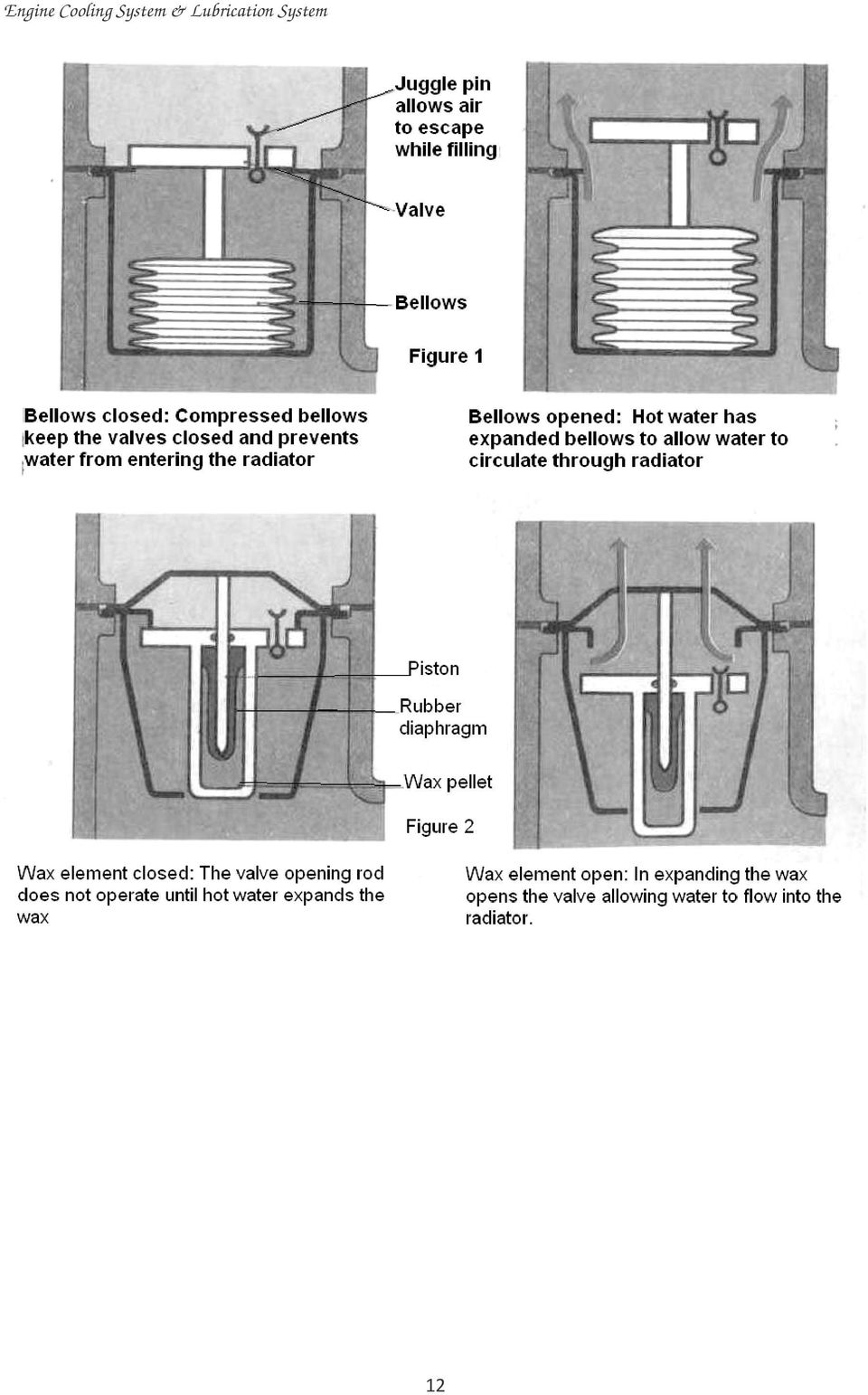
6 through these jackets. In most of the automotive engines, the coolant jacket is cast integral Thermosyphon cooling system: When a vessel of cold water is heated, the hot water will tend to rise (by virtue of its lower density) and its place will be taken over by cold water. This causes a definite circulation within the water mass from top to bottom and vice versa. This is called natural convection. The Thermosyphon, circulation cooling system shown in fig.1, works on this principle. In the thermosyphon circulation cooling system, when the engine is cold the whole water is at the same temperature and is at rest. When the engine is

7 operating, the water around the cylinder heads and cylinder walls gets heated and flow up to the top header tank of the radiator. Now the cold water from the lower part of the radiator flows and fills the coolant spaces in the cylinder head and the cylinder block. The hot water flows downward through the radiator tubes. This water is cooled by the stream that flows past the tubes. Air is sucked by the fan which is driven by the engine crankshaft. In this system, the water circulation through the cylinder, cylinder head and the radiator is by natural means. For success in operation, the passages through the jackets and radiator should be free and the connecting pipes large. Further the jackets should be placed as low as possible relatively to the radiator, in order that the hot leg shall have as great a height as possible. During operation the water level must on no account be allowed to fall below the level of the delivery pipe to the radiator top. If this happens, water circulation will cease.

8 In general the thermo-syphon system requires a larger radiator and carries a greater body of water than the pump circulation system. Further, a somewhat excessive temperature difference is necessary to produce the requisite circulation. On the other hand, to some extent it automatically prevents the engine being run too cold. The thermo-syphon circulation cooling system is simpler in construction and operation. This system is used in some motor cars Forced circulation cooling system (or Pump circulation cooling system): Present day automotive engines are of larger power output and operate at higher speeds. As such they tend to operate at higher temperatures. The rate of coolant circulation in these engines must be greater in order to increase the cooling effect. This necessitates the use of a water pump in these engines. The pump ensures forced circulation of the coolant. The pump draws cold water from the radiator bottom tank, circulates it through the engine coolant jacket and pushes it back to the hot water tank (top tank of the radiator). The pump assisted forced circulation system can be seen in figure 2.
: Present day automotive engines are of larger power output and operate at higher speeds.")
9 1. Radiator: In mobile units, the hot water let out by the engine must be cooled by some method and then re-circulated by the cooling system. Radiator is widely used for this purpose in transport vehicles. The radiator presents a large amount of cooling surface to the air so that the water passing downward through it in thin steams is cooled efficiently. The practical factors that govern the choice of the available radiator are available space, air flow resistance and cost. The details of the radiator are seen in the figure.

10 Details of the radiator and thermostat Radiators constructed at present are mainly of two types: 1. Vertical water tube type (Down flow) and, 2. Cellular type (Cross flow). In the vertical water tube type, the water falls through a nest of tubes from an upper header tank to a lower tank and air flows horizontally between the tubes. In the cellular type, the air flows horizontally through short tubes assembled honeycomb fashion with small clearances between them through which the water circulates vertically from top to bottom. The amount of heat that can be dissipated by a radiator depends upon the following: 1. Relative wind velocity, 2. Air density and humidity,

11 3. Water and air temperature, 4. Cooling (or heat transfer) surface provided, 5. Ratio of tube depth to diameter, 6. Conductivity of the metal used, 7. Design of radiator and its disposition. 3. Thermostat Types of Thermostat 1. Bellow type (Figure 1), 2. Wax type (Figure 2) A Pump, B - Thermostat

12
13 3.7 LUBRICATION SYSTEM Lubrication circuit is one of the most important ones in the engine. The engine cannot run smoothly for more than a few minutes without the lubricating oil. Whenever two metallic surfaces move over each other under direct contact, dry or solid friction is produced. This is due to the irregularities on the two surfaces interlocking each other. The dry friction thus. created produces a lot of heat and results in wear of the metal surface. 3.8 Purpose of lubrication 1. To reduce friction between the moving parts. 2. To reduce wear of the moving parts by way of lubricating the surfaces and keeping them apart. 3. Remove heat from engine parts by acting as a cooling agent. To keep down the temperature of the moving parts and thus prevent scuffing and seizure. 4. To act as a seal and prevent leakage between the parts such as pistons, piston rings and cylinders. 5. Absorb shocks between bearings and other engine parts, thus reducing engine noise and extending engine life. 6. Acts as a cleaning agent. To wash away acidic accumulation and abrasive metal worn from the friction surfaces. 3.9 Crankcase ventilation In the case of four stroke engines, air must circulate through the crankcase, when the engine is running. This removes the hot lubricating oil vapors and blow by from the crankcase. For entry of air and exit of the gases, the crankcase is provided with a breather tube. The air entry into the crankcase also cools the oil to some extent. However, discharging the crankcase vapors into the atmosphere

14 causes air pollution. To prevent atmosphere pollution, modern engines have a positive crankcase ventilation (PCV) system. In this case, the crankcase is connected by a pipe to the inlet manifold. This enables the oil vapors to be sucked into the inlet manifold during engine suction and burned Methods of lubrication: The different parts of an engine are lubricated by anyone combinations of the following methods. 1. Mechanical system Splash lubrication 2. Pressure lubrication system. a. Wet sump lubrication system b. Dry sump lubrication system. 3. Semi pressure lubrication system Splash lubrication: In the splash lubrication system, the oil retained in the oil pan is churned and splashed up by the internal parts of the engine (connecting rod big end and crankshaft) into a combination of liquid and mist. This oil mist is sprayed over the interior of the engine i.e. on the cylinder walls and on the underside of the piston crown. Some of the oil splashed gets collected in pockets over the main bearings. The collected oils then flow through the bearings by means of oil hole and grooves in the bearing surfaces. In one design, the connecting rod big end caps have scoops. These scoops pick up oil from the oil pan, during the lower ends of the connecting rod travel. The connecting rod caps have drilled holes. Through these holes, part of the oil picked up by the scoop reaches the end bearings. The remaining oil lubricates the rest of the engine parts by splash i.e. the throwing of oil by the connecting rods, crankshaft and other oiled moving parts.

15 In another design, the connecting rod big end cap has thin projections. These projections improve oil splashing PRESSURE LUBRICATION SYSTEM In the pressure lubrication system, the lubricating oil is pumped under pressure to the various engine bearings. The oil is delivered by an oil pump under a pressure of 1.30 to 1.40 kscm into an oil gallery or distributor duct. This gallery distributes oil to the various engine parts and bearings. The oil pump is driven by the engine crankshaft or camshaft. This system can be seen in figure. The crankshaft main bearing (each one) is pressure fed from the main oil gallery. Internal drilled holes (or ducts) in the webs of the crankshaft conduct oil from the main bearings to the connecting rod big end bearings. The oil flows from the big end bearing through the long hole drilled in the shank of the connecting rod to the wrist. pin. The lubricating oil flow through a bearing is controlled by maintaining limited clearance all around between a round bearing and a round shaft. The clearance between a round bearing and a round shaft. The clearance between the two is called oil clearance. Proper clearance must exist and this varies with different engines, but mm is a typical clearance.
 is pressure fed from the main oil gallery.")
16 When there is excessive clearance, the oil pump cannot build up normal pressure. Excessive clearance can also cause some bearings to fail due to oil starvation. On the other hand, if the oil clearances are insufficient, then there will be metal contact between the bearing and the shaft journal. Extremely rapid wear and quick failure will occur. Further, there will not be enough oil throw off for adequate lubrication of the cylinder walls, pistons and rings. In 1 head engines oil is fed under pressure to the valve mechanisms in the head. For example, some engines have the rocker arms mounted on hollow shafts. These shafts feed oil to the rocker arms. Some engines with independently mounted rocker arms have hollow mounting studs. These studs feed oil gallery in the hed to the rocker arm ball pivots. On other engines, the oil flows up through hollow push rods to lubricate the valve stems and other valve train parts. The oil spills off the rocker arms and provides lubrication for the valve stems and other valve train parts, the oil spills off the rocker arms and provides

17 lubrication for the valve stems and push rod and valve stem tips. Therefore, all valve mechanism parts are adequately lubricated. Cylinder walls are lubricated by splashing oil thrown off from the connecting rod bearings. Some engines have oil spit holes or groove in the connecting rods that index with drilled holes in the crankpin journals with each revolution. As this happens a stream of oil is spit, or thrown, onto the cylinder walls. When oil spit that holes are not used, the engine relies on oil that flows through the side clearance between the side of the connecting rod and the crankshaft for cylinder wall lubrication. In many engines, the piston pins are lubricated with oil scraped off the cylinder walls. The pistons have grooves, holes, or slots to feed oil from the oil ring groove to the piston pin bosses. Lubrication of piston pin, camshaft bearings, rocker arm shaft, rocker arm, cam and tappet surfaces can be seen in figure.

18 Semi pressure lubrication system The semipressure lubrication system is a combination of splash and pressure lubrication system. Most automotive engines use this system. This is more simple and less costly than the complete pressure lubrication system. This system also enables bearing loads and engine speeds than for the splash system Wet sump lubrication In the wet sump lubrication system, the main oil supply is kept in the sump which is below the engine cylinder in the crankcase. The oil pump draws oil from the crankcase and forces it through the lubricating oil filters to the various parts of the engine. This system is widely used incars and trucks.

19 In some engines, the oil pump is submerged in the sump oil. Some designs use tiling intake pipe and strainer unit. Where there is no oil hole in the connecting rod shank, the cylinder walls and piston pins are lubricated by the spray of oil that is forced out of the connecting rod bearings and thrown by the revolving cranks. This spray also lubricates many exposed internal parts. A separate line supplies lubricant to the accessories and their drive shafts, valves and rocker arms. Used oil drains back into the crankcase by gravity for recirculation Dry sump lubrication The dry sump lubrication is used in more expensive cars. In the dry sump pressure lubrication system, there is no oil sump in the crankshaft chamber. In this system, the oil is kept either in a separate tank or reservoir, provided with cooling fins. Two pumps are used in this system. One pump sucks the oil from the reservoir and forces it under pressure to the various bearings of the engine, as in the wet sump system. The other pump (also called scavenger oil pump) is of large capacity. This pump sucks oil which drains down to the bottom of the crankshaft chamber, and returns it to the oil reservoir.

20 The main advantage of the dry sump lubrication system is that the oil is cooled during its circulation. As such, the oil has better lubricating value. Dry sump system is suitable for engines fitted to vehicles which may have to work in inclined positions.

21 Full flow and partial or by-pass flow pressure system The full flow system and the partial or bypass flow system can be seen in figure. The full flow lubrication system is one in which the entire quantity of oil delivered by the pump is forced through the oil filter before the oil filter reaches the various parts of the engine. It is the most common and widely used type. The bypass lubrication system does not filter all of the oil that enters the engine bearings. It filters some of the extra oil not needed by the bearings.
22 ******************* Exercise 3 1. What is the necessity of Cooling? 2. What are the effects of engine overheating? 3. What are the effects of Over cooling and under cooling? 4. What are the advantages and disadvantages of air cooling? 5. What is thermosyphon cooling? Explain with a neat sketch working themosyphon cooling? 6. Write a short note on with a neat sketch working of i) Forced circulation cooling system ii) Thermostat cooling 7. What is the purpose of lubrication? 8. What are the methods of lubrication? Explain with a neat sketch working of splash lubrication. 9. With a neat sketch explain working of a Pressure lubrication system 10. Explain briefly with a neat sketch working of Dry sump lubrication
EXPERIMENT NO. 3. Aim: To study the construction and working of 4- stroke petrol / diesel engine.
 EXPERIMENT NO. 3 Aim: To study the construction and working of 4- stroke petrol / diesel engine. Theory: A machine or device which derives heat from the combustion of fuel and converts part of this energy
B Dinesh Prabhu, Asst. Professor, P E S College Engg., Mandya, KARNATAKA 1
 Firing Order Every engine cylinder must fire once in every cycle. This requires that for a four-stroke fourcylinder engine the ignition system must fire for every 180 degrees of crank rotation. For a sixcylinder
Piston Diagnosis A rough Guide
 Piston Diagnosis A rough Guide The process of examining used pistons can tell us a lot of helpful information on the condition of an engine. When engine failure does occur the piston is likely to take
- Service Bulletin - Pistons.
 Normal combustion: is smooth and even from the spark plug through the top of the chamber. 1 2 3 Spark occurs Combustion moves smoothly across chamber Combustion and power completed Pre-Ignition: occurs
FS Lubricants. Oil Analysis Program
 FS Lubricants Oil Analysis Program What can an oil analysis do for you? 1. Establish safe and proper drain intervals. 2. Provide a reduction in unforeseen breakdowns. 3. Reduce down time. 4. Minimize the
UNIT 3 AUTOMOBILE ELECTRICAL SYSTEMS
 UNIT 3 AUTOMOBILE ELECTRICAL SYSTEMS Automobile Electrical Structure 3.1 Introduction Objectives 3.2 Ignition System 3.3 Requirement of an Ignition System 3.4 Types of Ignition 3.4.1 Battery or Coil Ignition
5.2. Vaporizers - Types and Usage
 5.2. Vaporizers - Types and Usage 5.2.1. General Vaporizers are constructed in numerous designs and operated in many modes. Depending upon the service application the design, construction, inspection,
BUT PRECAUTIONS MUST BE TAKEN OR SERIOUS BURNS CAN RESULT.
 Cooling System Operation Below is an explanation of this system's operation Radiator The radiator is a device designed to dissipate the heat which the coolant has absorbed from the engine. It is constructed
New Trends in the Field of Automobile Air Conditioning
 New Trends in the Field of Automobile Air Conditioning E. Janotkova and M. Pavelek Department of Thermomechanics and Environmental Engineering Brno University of Technology, 61669 Brno, Czech Republic
Engine Heat Transfer. Engine Heat Transfer
 Engine Heat Transfer 1. Impact of heat transfer on engine operation 2. Heat transfer environment 3. Energy flow in an engine 4. Engine heat transfer Fundamentals Spark-ignition engine heat transfer Diesel
Section 11 - System Diagrams
 Section 11 System Diagrams Page 11-1 Section 11 - System Diagrams Section Contents Page Overview...11-3 Flow Diagram, Fuel System...11-4 Flow Diagrams, Lubricating Oil System...11-5 Flow Diagrams, Cooling
ENGINE COOLING SYSTEM
 ENGINE COOLING SYSTEM 1988 Toyota Celica 1987-88 TOYOTA Engine Cooling Systems Celica DESCRIPTION The basic liquid cooling system consists of a radiator, water pump, thermostat, cooling fan, pressure cap,
Section 6 - System Diagrams
 Section 6 System Diagrams Page 6-1 Section 6 - System Diagrams Section Contents Page Overview...6-3 Flow Diagram, Fuel System...6-4 Flow Diagrams, Lubricating Oil System...6-5 Flow Diagrams, Cooling System...6-8
MCI 35.80a AUTOMOTIVE ENGINE MAINTENANCE AND REPAIR MARINE BARRACKS WASHINGTON, D.C.
 MCI 35.80a MARINE CORPS INSTITUTE AUTOMOTIVE ENGINE MAINTENANCE AND REPAIR MARINE BARRACKS WASHINGTON, D.C. UNITED STATES MARINE CORPS MARINE CORPS INSTITUTE 912 POOR STREET SE WASHINGTON, DC 20391-5680
INTERNATIONAL FIRE TRAINING CENTRE FIREFIGHTER INITIAL PUMPS AND PRIMERS. Throughout this note he means he/she and his means his/hers.
 INTERNATIONAL FIRE TRAINING CENTRE FIREFIGHTER INITIAL PUMPS AND PRIMERS Throughout this note he means he/she and his means his/hers. Areas of bold type are considered to be of prime importance. INTRODUCTION
Turbo Tech 101 ( Basic )
") Turbo Tech 101 ( Basic ) How a Turbo System Works Engine power is proportional to the amount of air and fuel that can get into the cylinders. All things being equal, larger engines flow more air and as
Turbo Tech 101 ( Basic ) How a Turbo System Works Engine power is proportional to the amount of air and fuel that can get into the cylinders. All things being equal, larger engines flow more air and as
Chapter 7 Hydraulic System Troubleshooting
 Chapter 7 Hydraulic System Troubleshooting General The following troubleshooting information is provided as a general guide to identify, locate and correct problems that may be experienced with the hydraulic
A Guide to Trouble-Free Cooling Towers
 A Guide to Trouble-Free Cooling Towers A basic understanding of cooling tower operation and maintenance will help keep a cooling water system running in top condition, year after year By David M. Suptic
Table V. Troubleshooting Checklist for Refrigeration Systems. Air or non-condensable gas in system. Inlet water warm.
 Table V Troubleshooting Checklist for Refrigeration Systems TROUBLE POSSIBLE CAUSE CORRECTIVE MEASURE High condensing pressure. Low condensing pressure. Air or non-condensable gas in system. Inlet water
OD1619 PRINCIPLES OF INTERNAL COMBUSTION ENGINES
 SUBCOURSE OD1619 EDITION 8 PRINCIPLES OF INTERNAL COMBUSTION ENGINES US ARMY BRADLEY FIGHTING VEHICLE SYSTEMS MECHANIC CORRESPONDENCE COURSE MOS/SKILL LEVEL: 63T30 PRINCIPLES OF INTERNAL COMBUSTION ENGINES
Heating and Air Conditioning, Part 1
 1 Heating and Air Conditioning, Part 1 AUTOMOTIVE HEATING AND ENGINE COOLING SYSTEMS The Automotive Engine Creates Heat An automobile or truck engine is basically an air pump. The fuel that s fed to the
Engine Troubleshooting Guide Shortcuts to Costly Engine Diagnostics
 Engine Troubleshooting Guide Shortcuts to Costly Engine Diagnostics Includes Sections on: Low Power and Uneven Running High Oil Temperature Excess Oil Consumption Engine Stops High Cylinder Head Temperature
Mechanical shaft seal types and sealing systems
 Chapter 2 Mechanical shaft seal types and sealing systems 1. Mechanical shaft seal types 2. Sealing systems 3. Selecting a mechanical shaft seal Mechanical shaft seal types and sealing systems 1. Mechanical
912. The engine for construction equipment.
 912. The engine for construction equipment....... 24-82 kw at 1500-2500 min -1 These are the characteristics of the 912: Air-cooled 3-, 4-, 5-, 6-cylinder naturally aspirated in-line-engines. Direct injection.
Trouble Shooting. Pump
 Trouble Shooting Pump Trouble Possible Cause Remedy Oil leaking in the area of water pump crankshaft Worn crankshaft seal, bad bearing, grooved shaft, or failure of retainer o-ring. Excessive play on crankshaft
01-3 6820-11 6820-11 AIR CONDITIONER GENERAL 1. SPECIFICATIONS AIR CONDITIONER REXTON 2010.01
 682011 013 GENERAL 1. SPECIFICATIONS 682011 014 682011 2. REPAIR INSTRUCTIONS 1) Precautions for Working with R134a R12 refrigerant and R134a refrigerant are not compatible. These refrigerants must never
INTERNAL COMBUSTION (IC) ENGINES
 ENGINES") INTERNAL COMBUSTION (IC) ENGINES An IC engine is one in which the heat transfer to the working fluid occurs within the engine itself, usually by the combustion of fuel with the oxygen of air. In external
INTERNAL COMBUSTION (IC) ENGINES An IC engine is one in which the heat transfer to the working fluid occurs within the engine itself, usually by the combustion of fuel with the oxygen of air. In external
Basic Hydraulics and Pneumatics
 Basic Hydraulics and Pneumatics Module 1: Introduction to Pneumatics PREPARED BY IAT Curriculum Unit March 2011 Institute of Applied Technology, 2011 ATM 1122 Basic Hydraulics and Pneumatics Module 1:
Skills Standards MEDIUM/HEAVY DUTY TRUCK: DIESEL ENGINE REPAIR TECHNICIAN OD32151 ALIGNED WITH ASE/NATEF
 Skills Standards MEDIUM/HEAVY DUTY TRUCK: DIESEL ENGINE REPAIR TECHNICIAN OD32151 ALIGNED WITH ASE/NATEF Competency-Based Education: OKLAHOMA S RECIPE FOR SUCCESS BY THE INDUSTRY FOR THE INDUSTRY Oklahoma
Overview. Introduction Cooling Tower Basics Principles of Operation Types of Cooling Towers Common Applications Design Considerations
 Stephen Lowe ASHRAE Hampton Roads Chapter Past President AECOM Design Mechanical Engineering Discipline Manager, Virginia Beach Division Professional Engineer Commonwealth of Virginia, NCEES BSME University
Kobelco Extended Warranty Program. www.kobelco-europe.com
 Kobelco Extended Warranty Program www.kobelco-europe.com Kobelco Extended Warranty is a convenient, value added way to give your Kobelco customers added security and peace of mind. Benefits of the Kobelco
AIR CONDITIONING TECHNOLOGY
 AIR CONDITIONING TECHNOLOGY PART 9 Water Cooled Condensers & Cooling Towers IN LAST month s article we looked at how Air Cooled Condensers are used to transfer the total heat of rejection from the air
How much do you know about HVAC? Try testing yourself with the following questions and then take a look at the answers on the following page.
 Demystifying HVAC Test Your HVAC Knowledge By Ron Prager How much do you know about HVAC? Try testing yourself with the following questions and then take a look at the answers on the following page. 1)
Unit 24: Applications of Pneumatics and Hydraulics
 Unit 24: Applications of Pneumatics and Hydraulics Unit code: J/601/1496 QCF level: 4 Credit value: 15 OUTCOME 2 TUTORIAL 2 HYDRAULIC AND PNEUMATIC CYLINDERS The material needed for outcome 2 is very extensive
Why and How we Use Capacity Control
 Why and How we Use Capacity Control On refrigeration and air conditioning applications where the load may vary over a wide range, due to lighting, occupancy, product loading, ambient weather variations,
HS-901(A) BASIC STEAM HEATING SYSTEMS
 BASIC STEAM HEATING SYSTEMS") HS-901(A) BASIC HEATING SYSTEMS One-Pipe Two-Pipe Basic Steam Heating Systems One-pipe steam heating system EQUALIZER SAFETY FACTOR STATIC HEAD PRESSURE DROP 2" HEATING UNIT 15" DRIP CONNECTION In a one-pipe,
HS-901(A) BASIC HEATING SYSTEMS One-Pipe Two-Pipe Basic Steam Heating Systems One-pipe steam heating system EQUALIZER SAFETY FACTOR STATIC HEAD PRESSURE DROP 2" HEATING UNIT 15" DRIP CONNECTION In a one-pipe,
Hydraulic Troubleshooting PRESENTED BY
 Hydraulic Troubleshooting PRESENTED BY NORMAN KRONOWITZ Introduction Welcome to the CMA/Flodyne/Hydradyne s Hydraulic Troubleshooting presentation. We will introduce many aspects of troubleshooting hydraulic
COOLING SYSTEM Section Page
 5 COOLING SYSTEM Section Page 5.1 COOLANT PRE-HEATER... 5-3 5.2 COOLANT PUMP NON-EGR ENGINE... 5-7 5.3 COOLANT PUMP EGR ENGINE... 5-13 5.4 FRONT CONNECTOR HOUSING NON-EGR ENGINE... 5-17 5.5 FRONT CONNECTOR
1/29/2008 DR70. Baja Motorsports Inc. P.O. Box 61150 Phoenix, AZ 85082 Toll Free: 888-863-2252 PART NUMBERS PRICES ARE SUBJECT TO CHANGE 1 of 43
 DR70 Toll Free: 888-863-2252 PART NUMBERS PRICES ARE SUBJECT TO CHANGE 1 of 43 CYLINDER & CYLINDER HEAD 1 DR70-001 883099044472 CYLINDER 1 1 2 DR70-002 883099044489 GASKET, CYLINDER 1 1 3 DR70-003 883099044496
FUEL & FUEL SYSTEM PROPERTIES OF FUEL
 FUEL & FUEL SYSTEM PROPERTIES OF FUEL Fuel is a substance consumed by the engine to produce energy. The common fuels for internal combustion engines are: 1. Petrol 2. Power kerosene 3. High speed diesel
4000 Series 4008TAG2A Diesel Engine ElectropaK 947 kwm @ 1500 rpm
 The Perkins 4000 Series family of 6, 8, 12 and 16 cylinder diesel engines was designed in advance of today s uncompromising demands within the power generation industry and includes superior performance
MAN - MERCEDES - BENZ
 SAYFA: 1 10100 10102 10103 355 353 06 15 355 353 03 15 346 353 08 15 AXLE GEAR AXLE GEAR AXLE (WITH BUSHING TYPE) (WITH BUSHING TYPE) (WITH BUSHING TYPE) 2521 2517-2521-2622 10104 10105 10106 308 350 00
Glossary of Heating, Ventilation and Air Conditioning Terms
 Glossary of Heating, Ventilation and Air Conditioning Terms Air Change: Unlike re-circulated air, this is the total air required to completely replace the air in a room or building. Air Conditioner: Equipment
Boiler Preparation, Start-Up and Shutdown
 Boiler Preparation, Start-Up and Shutdown Learning Outcome When you complete this module you will be able to: Describe the basic preparation of a boiler for start-up, and the start-up and shutdown procedures.
1013 E. The engine for agricultural equipment.
 1013 E. The engine for agricultural equipment.... -186 kw at 2300 rpm These are the characteristics of the 1013 E: Modern water-cooled 4- and 6-cylinder in-line engine Turbocharging with charge air cooling
Factory owners must ensure the boiler is:
 Factory owners must ensure the boiler is: * Registered with the Boilers and Pressure Vessels Division, Labour Department * Examined by an appointed examiner and has a valid certificate of fitness * Supervised
Unit 24: Applications of Pneumatics and Hydraulics
 Unit 24: Applications of Pneumatics and Hydraulics Unit code: J/601/1496 QCF level: 4 Credit value: 15 OUTCOME 2 TUTORIAL 3 HYDRAULIC AND PNEUMATIC MOTORS The material needed for outcome 2 is very extensive
Volkswagen B3 Passat General-Engine 4 CYL. 19 Engine - Cooling System (Page GR-19)
") 19 Engine - Cooling System (Page GR-19) Cooling system draining and filling general information Body components, layout Engine components, layout Radiator fan run-on checking Recommended mixture ratios
19 Engine - Cooling System (Page GR-19) Cooling system draining and filling general information Body components, layout Engine components, layout Radiator fan run-on checking Recommended mixture ratios
Diesel: Troubleshooting
 Diesel: Troubleshooting Probable Cause Engine not starting Hard to start engine Runs rough at lower RPM Lack of power Diesel knock / pinking Black White Blue Low compression X X X Low fuel pressure X X
STATE UNIVERSITY OF NEW YORK COLLEGE OF TECHNOLOGY CANTON, NEW YORK COURSE OUTLINE AUTO 220 INTERNAL COMBUSTION ENGINES
 STATE UNIVERSITY OF NEW YORK COLLEGE OF TECHNOLOGY CANTON, NEW YORK COURSE OUTLINE AUTO 220 INTERNAL COMBUSTION ENGINES Prepared By: BRANDON BALDWIN CANINO SCHOOL OF ENGINEERING TECHNOLOGY AUTOMOTIVE TECHNOLOGY
Engine. 204-1890 Strobe light, 110V 204-1891 Strobe light, 220V 204-458 Replacement bulb. 204-1057 Compression gauge. 204-166 Dial indicator
 The Strobe light checks the unit for: Balance of operating machinery RPM of motors, engine pulleys, fans, etc. Observe belt slippage Strobe light will stop action at speeds from 200 to 6000 RPM 204-1890
Cooling system components, removing and installing
 Volkswagen Touareg 3.2 - Cooling system components, removing and installing Page 1 / 24 19-1 Cooling system components, removing and installing Warning! Hot steam may escape when opening expansion tank.
SLP 1.85 Ratio Offset Rocker Arms with Valve Springs, LS3
 PART #50190 SLP 1.85 Ratio Offset Rocker Arms with Valve Springs, LS3 PACKING LIST Before installation, use this check list to make sure all necessary parts have been included. ITEM QTY CHECK PART NUMBER
CNC Ported Big Valve Cylinder Heads. Performance Intake Manifold. Forged Pistons (Engine set with rings, pins and clips)
") Performance Engine Assemblies 20001721 2.0lt Performance Crate Engine 205BHP 20001722 2.0lt Performance Crate Engine 225BHP 20001723 2.0lt Performance Crate Engine 255BHP 20001725 2.3lt Performance Crate
Performance Engine Assemblies 20001721 2.0lt Performance Crate Engine 205BHP 20001722 2.0lt Performance Crate Engine 225BHP 20001723 2.0lt Performance Crate Engine 255BHP 20001725 2.3lt Performance Crate
Specific Volume of Liquid (Column 7). The volume per unit of mass in cubic feet per pound.
. The volume per unit of mass in cubic feet per pound.") Steam Tables What They Are How to Use Them The heat quantities and temperature/ pressure relationships referred to in this Handbook are taken from the Properties of Saturated Steam table. Definitions of
Steam Tables What They Are How to Use Them The heat quantities and temperature/ pressure relationships referred to in this Handbook are taken from the Properties of Saturated Steam table. Definitions of
Cooling system components, removing and installing
 Engine BHW Cooling system components, removing and installing Page 1 / 24 19-1 Cooling system components, removing and installing Warning! When doing any repair work, especially in the engine compartment,
US ARMY LIGHT WHEEL VEHICLE MECHANIC MOS 63B SKILL LEVEL 3 COURSE WHEELED VEHICLE ENGINES SUBCOURSE NO. OD 1001
 US ARMY LIGHT WHEEL VEHICLE MECHANIC MOS 63B SKILL LEVEL 3 COURSE WHEELED VEHICLE ENGINES SUBCOURSE NO. OD 1001 United States Army Combined Arms Support Command Ordnance Missile and Munitions Fort Lee,
BSM MOTOR DRIVEN CENTRIFUGAL PUMPS
 PRINCIPLE OF OPERATION A hydraulically and dynamically balanced impeller with raised vane sections discharges liquid as a result of the centrifugal force developed in rotation. The head developed is entirely
MAINTENANCE OF SMALL WATER SUPPLY, SANITATION AND IRRIGATION SCHEMES
 MAINTENANCE OF SMALL WATER SUPPLY, SANITATION AND IRRIGATION SCHEMES John van Rijn INDEVELOPMENT MAINTENANCE OF SMALL WATER SUPPLY, SANITATION AND IRRIGATION SCHEMES Any part of this publication may be
STEAM HEATING SYSTEM TROUBLESHOOTING GUIDE
 Page 1 of 9 PURPOSE Steam is the most commonly used heating medium for maintaining process temperatures. Compared to other heating media, steam contains a significant amount of heat energy, and this heat
MAINTENANCE OF WHEELMOVE IRRIGATION SYSTEMS
 MAINTENANCE OF WHEELMOVE IRRIGATION SYSTEMS F. Richard Beard, Agricultural Equipment, Structures and Electricity Robert W. Hill, Biological & Irrigation Engineering Boyd Kitchen, Uintah County Extension
Lesson 36 Selection Of Air Conditioning Systems
 Lesson 36 Selection Of Air Conditioning Systems Version 1 ME, IIT Kharagpur 1 The specific objectives of this chapter are to: 1. Introduction to thermal distribution systems and their functions (Section
E - THEORY/OPERATION
 E - THEORY/OPERATION 1995 Volvo 850 1995 ENGINE PERFORMANCE Volvo - Theory & Operation 850 INTRODUCTION This article covers basic description and operation of engine performance-related systems and components.
B1BBM2K1-806 DW10ATED ENGINE ENGINE INTRODUCTION DW10 1 - DESCRIPTION. Main structure of the DW10 engine :
 of 23 http://www.christiantena.pwp.blueyonder.co.uk/motor/peugeot/hdi/b... 7/12/2005 9:27 p.m. B1BBM2K1-806 DW10ATED ENGINE ENGINE INTRODUCTION DW10 1 - DESCRIPTION Main structure of the DW10 engine :
Signature and ISX CM870 Fuel System
 Signature and ISX CM870 Fuel System Cummins Ontario Training Center HPI-TP Fuel System Heavy Duty High Pressure Injection - Time Pressure Fuel System The fuel system developed for the Signature and ISX
11. COOLING SYSTEM 11-0 COOLING SYSTEM BET & WIN 50
 11 COOLING SYSTEM SERVICE INFORMATION------------------------------------------------ 11-1 TROUBLESHOOTING----------------------------------------------------- 11-1 RADIATOR ------------------------------------------------------------------
WASHING PROCESS OF CARGO TANKS ON TANKERS FOR TRANSPORTATION OF CRUDE OIL
 WASHING PROCESS OF CARGO TANKS ON TANKERS FOR TRANSPORTATION OF CRUDE OIL Siniša Stojan, Ph.D. student Damir Dražić, Ph.D. student Brodotrogir, HR - 21220 Trogir, Croatia sinisa.stojan@brodotrogir.hr,
CDS TROUBLESHOOTING SECTION I. VACUUM. 1.0. Weak vacuum at wand. Gauge reads normal (10hg to 14hg)
") CDS TROUBLESHOOTING SECTION I. VACUUM 1.0. Weak vacuum at wand. Gauge reads normal (10hg to 14hg) 1.1. Clogged hoses or wand tube. Disconnect hoses and carefully check for an obstruction. 1.2. Excessive
CDS TROUBLESHOOTING SECTION I. VACUUM 1.0. Weak vacuum at wand. Gauge reads normal (10hg to 14hg) 1.1. Clogged hoses or wand tube. Disconnect hoses and carefully check for an obstruction. 1.2. Excessive
Engine Friction and Lubrication
 Engine Friction and Lubrication Engine friction terminology Pumping loss Rubbing friction loss Engine Friction: terminology Pumping work: W p Work per cycle to move the working fluid through the engine
Subpart 1. Installation. All plumbing systems must be. installed and tested according to this chapter and chapter 4715,
 4658.4500 PLUMBING SYSTEMS; NEW CONSTRUCTION. Subpart 1. Installation. All plumbing systems must be installed and tested according to this chapter and chapter 4715, the Minnesota Plumbing Code. Subp. 2.
Robison On Rovers Carbon Fouling A New Kind of Valve Job
 Robison On Rovers #2, February 20, 2000 By John Robison 1,750 words Robison On Rovers Carbon Fouling A New Kind of Valve Job Many of you have heard about the carbon fouling problem affecting newer Discoveries
Pollution by 2-Stroke Engines
 Pollution by 2-Stroke Engines By Engr. Aminu Jalal National Automotive Council At The Nigerian Conference on Clean Air, Clean Fuels and Vehicles, Abuja, 2-3 May 2006 Introduction to the 2-Stroke Engine
Using Portable Spot Air Conditioners in Industrial Applications
 Using Portable Spot Air Conditioners in Industrial Applications Cooling People, Processes and Equipment In today s highly competitive manufacturing sector, companies are constantly looking for new ways
LECTURE 28 to 29 ACCUMULATORS FREQUENTLY ASKED QUESTIONS
 LECTURE 28 to 29 ACCUMULATORS FREQUENTLY ASKED QUESTIONS 1. Define an accumulator and explain its function A hydraulic accumulator is a device that stores the potential energy of an incompressible fluid
Heating Water by Direct Steam Injection
 Heating Water by Direct Steam Injection Producing hot water by direct steam injection provides a solution where large volumes of hot water at precise temperatures are required, and where energy and space
The soot and scale problems
 Dr. Albrecht Kaupp Page 1 The soot and scale problems Issue Soot and scale do not only increase energy consumption but are as well a major cause of tube failure. Learning Objectives Understanding the implications
OUTCOME 2 INTERNAL COMBUSTION ENGINE PERFORMANCE. TUTORIAL No. 5 PERFORMANCE CHARACTERISTICS
 UNIT 61: ENGINEERING THERMODYNAMICS Unit code: D/601/1410 QCF level: 5 Credit value: 15 OUTCOME 2 INTERNAL COMBUSTION ENGINE PERFORMANCE TUTORIAL No. 5 PERFORMANCE CHARACTERISTICS 2 Be able to evaluate
PROPERLY WORKING FUEL SYSTEM
 PROPERLY WORKING FUEL SYSTEM FUEL SYSTEMS The fuel systeem is the most sophisticated, expensive and critical of all engines systems. Engine performance, economy and durability depend on proper performance
1/29/2008 DR50. Baja Motorsports Inc. P.O. Box 61150 Phoenix, AZ 85082 Toll Free: 888-863-2252 PART NUMBERS PRICES ARE SUBJECT TO CHANGE 1 of 45
 DR50 Toll Free: 888-863-2252 PART NUMBERS PRICES ARE SUBJECT TO CHANGE 1 of 45 CYLINDER & CYLINDER HEAD Part UPC Number Description Baja Description 1 DR50-001 842645074424 CYLINDER 1 1 2 DR50-002 842645074431
Table Z. Troubleshooting Chart for Air Conditioners. Cause
 Troubleshooting Chart for Air Conditioners Type of Unit Complaint Cause With open-type compressor Electric motor will not start Power failure Check circuit for power source Compressor stuck Locate cause
HEATER, AIR CONDITIONING AND VENTILATION
 55-1 GROUP 55 HEATER, AIR CONDITIONING AND VENTILATION CONTENTS GENERAL DESCRIPTION 55-2 HEATER AND AIR CONDITIONING SYSTEM 55-4 HEATER CONTROL 55-6 A/C-ECU 55-7 A/C COMPRESSOR 55-9 CONDENSER 55-9 DUCT
REMAN ENGINES APPLICATION GUIDE
 REMAN ENGINES APPLICATION GUIDE CNH REMAN ENGINES Today, there are more reasons than ever to choose CNH Remanufactured s for your equipment. From more engine choices to less downtime during installation,
OIL CONSIDERATION TO LENGTHEN ENGINE LIFE
 OIL CONSIDERATION TO LENGTHEN ENGINE LIFE Farm Machinery Fact Sheet FM-19 By Dr. Von H. Jarrett, Extension Agricultural Perhaps nothing will add to the life of an automobile, truck, tractor or other fuel-powered
DR90. Baja Motorsports Inc. P.O. Box 61150 Phoenix, AZ 85082 Toll Free: 888-863-2252 PART NUMBERS AND PRICES ARE SUBJECT TO CHANGE 1 of 51
 DR90 Toll Free: 888-863-2252 PART NUMBERS AND PRICES ARE SUBJECT TO CHANGE 1 of 51 CYLINDER & CYLINDER HEAD Part UPC Number Description Baja Description 1 DR90-001 842645048166 CYLINDER 1 1 2 DR90-002
Performance Analysis of a. for a Diesel Engine
 12 th GT-Suite User s Conference Performance Analysis of a Decompression Brake System for a Diesel Engine Ivan Miguel Trindade Vinicius J. M. Peixoto MWM International Motores November, 10th 2008 Presentation
Specifications for Volkswagen Industrial Engine
 Volkswagen 1 industrial engine Specifications for Volkswagen Industrial Engine AFD 1.9 ltr. TDI diesel engine EURO 2 Volkswagen AG, Wolfsburg Volkswagen AG reserves the right to introduce amendments or
Refrigeration Basics 101. By: Eric Nelson
 Refrigeration Basics 101 By: Eric Nelson Basics Refrigeration is the removal of heat from a material or space, so that it s temperature is lower than that of it s surroundings. When refrigerant absorbs
DR90. Baja Motorsports Inc. P.O. Box 61150 Phoenix, AZ 85082 Toll Free: 888-863-2252 PART NUMBERS AND PRICES ARE SUBJECT TO CHANGE 1 of 51
 DR90 Toll Free: 888-863-2252 PART NUMBERS AND PRICES ARE SUBJECT TO CHANGE 1 of 51 CYLINDER & CYLINDER HEAD 1 DR90-001 842645048166 CYLINDER 1 1 2 DR90-002 842645048173 GASKET, CYLINDER 1 1 3 DR90-003
Fuel System Description. Stromberg 175 CD-2 SE And SU-HS 6 Carburettors
 Fuel System Description Stromberg 175 CD-2 SE And SU-HS 6 Carburettors The B 20 A engine is fitted with a horizontal carburettor of typo Stromberg 175 CD-2 SE, see Fig. 60. The B 20 B engine In the l20
Hydraulic Trouble Shooting
 Hydraulic Trouble Shooting Hydraulic systems can be very simple, such as a hand pump pumping up a small hydraulic jack, or very complex, with several pumps, complex valving, accumulators, and many cylinders
BACKPACK SPRAYERS. MODEL NOS: KSP16 & KSP20 Part Nos: 3402270 & 3402275 OPERATING & MAINTENANCE INSTRUCTIONS GC04/12
 BACKPACK SPRAYERS MODEL NOS: KSP16 & KSP20 Part Nos: 3402270 & 3402275 OPERATING & MAINTENANCE INSTRUCTIONS GC04/12 INTRODUCTION Thank you for purchasing this CLARKE Sprayer, designed for use only with
Cooling system components, removing and installing
 Page 1 of 30 19-1 Cooling system components, removing and installing Notes: When the engine is warm the cooling system is under pressure. If necessary release pressure before commencing repair work. Secure
A discussion of condensate removal systems for clarifier and thickener drives for water and wastewater facilities.
 A discussion of condensate removal systems for clarifier and thickener drives for water and wastewater facilities. Richard L. Dornfeld, BSME, P.E. Staff Engineer September 25, 2014 Moisture can be a problem
Mechanical Seal Piping Plans
 Mechanical Seal Piping Plans Single Seals plans 01, 02, 03, 11, 13, 14, 21, 23, 31, 32, 41 Dual Seals plans 52, 53A, 53B, 53C, 54, 55 Quench Seals plans 62, 65A, 65B, 66A, 66B Gas Seals plans 72, 74, 75,
Grade 8 Science Chapter 9 Notes
 Grade 8 Science Chapter 9 Notes Force Force - Anything that causes a change in the motion of an object. - usually a push or a pull. - the unit for force is the Newton (N). Balanced Forces - forces that
Diesel Engine Fundamentals Course# ME406
 Diesel Engine Fundamentals Course# ME406 EZpdh.com All Rights Reserved Department of Energy Fundamentals Handbook MECHANICAL SCIENCE Module 1 Diesel Engine Fundamentals Diesel Engine Fundamentals DOE-HDBK-1018/1-93
Volkswagen Jetta, Golf, GTI 1999, 2000 2.8 Liter VR6 2V Engine Mechanical, Engine Code(s): AFP 17 Engine-Lubrication (Page GR-17)
: AFP 17 Engine-Lubrication (Page GR-17)") 17 Engine-Lubrication (Page GR-17) Lubrication system components, removing and installing Oil filter housing, disassembling and assembling Oil pan, removing and installing Oil pressure and oil pressure
17 Engine-Lubrication (Page GR-17) Lubrication system components, removing and installing Oil filter housing, disassembling and assembling Oil pan, removing and installing Oil pressure and oil pressure
MOTOR VEHICLE MECHANIC REPAIR CATEGORIES
 Chapter 8: Motor Vehicle Mechanic Repair Categories Page 1 CHAPTER 8 MOTOR VEHICLE MECHANIC REPAIR CATEGORIES Section 8-1 REQUIREMENT Section 10 of the Motor Vehicle Service and Repair Act (MCL 257.1310)
Evaluate, Clean, and Tune Guidance
 Evaluate, Clean, and Tune Guidance The Evaluate, Clean and Tune (ECT) process serves three essential purposes in the Weatherization Assistance Program (WAP). The first is to evaluate the existing system