Chapter 2. Circuit Analysis Techniques
|
|
|
- Simon Andrews
- 7 years ago
- Views:
Transcription
1 Chapter 2 Circuit Analysis Techniques 1
2 Objectives To formulate the node-voltage equations. To solve electric circuits using the node voltage method. To introduce the mesh current method. To formulate the mesh-current equations. To solve electric circuits using the mesh-current method. 2

3 Two Powerful Techniques for Circuit Analysis Nodal Analysis, based on a systematic application of Kirchhoff s current law (KCL Mesh Analysis, based on a systematic application of Kirchhoff s voltage law (KVL) we can analyze almost any circuit by obtaining a set of simultaneous equations that are then solved to obtain the required values of current or voltage. 3

4 Nodal Analysis So far, we have been applying KVL and KCL as needed to find voltages and currents in a circuit. Good for developing intuition, finding things quickly but what if the circuit is complicated? What if you get stuck? Systematic way to find all voltages in a circuit by repeatedly applying KCL: Node Voltage Method (Nodal Analysis). 4

5 Branches and Nodes ( reminder from last part) Branch: elements connected end-to-end, nothing coming off in between (in series) Node: place where elements are joined includes entire wire 5

6 Steps to Determine Node Voltages Method : Step 1 Select a node as the reference node. This is the reference Node The reference node is commonly called the ground since it is assumed to have zero potential. 6

7 Steps to Determine Node Voltages Method ( Cont.) Step 2 Assign voltages v 1, v 2,..., vn 1 to the remaining n 1 nodes. The voltages are referenced with respect to the reference node. Node 0 is the reference node (v = 0), while nodes 1 and 2 are assigned voltages v 1 and v 2. 7
, while nodes 1 and 2 are")
8 Steps to Determine Node Voltages Method ( Cont.) Step 3 Apply KCL to each of the n 1 non reference nodes add i 1, i 2, and i 3 as the currents through resistors R 1,R 2, and R 3, respectively. At by applying KCL gives node 1 node 2 8

9 Steps to Determine Node Voltages Method ( Cont.) Step 4 Use Ohm s law to express the branch currents in terms of node voltages. The key idea to bear in mind is that, since resistance is a passive element, by the passive sign convention, current must always flow from a higher potential to a lower potential. 9

10 Steps to Determine Node Voltages Method ( Cont.) Step 5 Solve the resulting simultaneous equations to obtain the unknown node voltages. 10

11 Node Voltage Equations (Resistors) 11

12 Example: The voltage drop from node X to a reference node (ground) is called the node voltage V x. The current through resistors can be expressed as Iab Va = Vb R 12

13 Example Calculate the node voltages Solution 13

14 At node 1 Multiply by 4 14

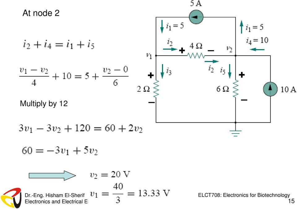
15 At node 2 Multiply by 12 15
16 Example Find the voltage at node 1, 2 & 3 Solve this example and handle it to me 16

17 Conclusion for Nodal Analysis Nodal analysis is simply writing KCL equations in a systematic way assuming all currents leaving. Nodes voltages are the circuit variables. Currents are expressed in terms of nodes voltages. The number of variables = Number of nodes

18 Nodal Analysis with Voltage Sources note that: A current source produces constant current in a give direction. I s is leaving Va I s Va Vb - I s is leaving Vb A Voltage source maintains the voltage constant between its terminals. Va = Vs No need to consider Va a circuit variable. Vs Va

19 If a voltage source is connected between the reference node and a non-reference node. simply set the voltage at the non-reference node equal to the voltage of the voltage source v1 = 10 V 19

20 If the voltage source (dependent or independent) is connected between two nonreference nodes. we apply both KCL and KVL to determine the node voltages. V 1 and v 2 are called a super-nodes as they enclose a (dependent or independent) voltage source connected between them and any elements connected in parallel. 20
 voltage source connected between them and any elements connected")
21 Steps to Determine Nodal Analysis with Voltage Sources. Step 1 Choose a reference node (ground, node 0) Step 2 Define unknown node voltages (those not connected to ground by voltage sources). Va, Vb, Step 3 Write KCL equation at each unknown node. How? Each current involved in the KCL equation will either come from a current source (giving you the current value) or through a device like a resistor. If the current comes through a device, relate the current to the node voltages using I -V relationship (like Ohm s law). 21
22 Step 4 Apply KCL to the supper node Super-node 22
23 Step 5 Apply KVL to the supper node Step 6 Solve the set of equations (N linear KCL equations for N unknown node voltages). 23
24 Example node voltage set R 1 V a R 3 V b + - I S V 1 R 2 R 4 Choose a reference node. reference node Define the node voltages (except reference node and the one set by the voltage source). Apply KCL at the nodes Va and Vb with unknown voltage. V V R V R Va V R a 1 + a + b = Vb V R 3 a + V R b 4 = I S Solve for Va and Vb in terms of circuit parameters. 24
25 Example Find the node voltage Solution Apply KCL at the super node Multiply by 4 25
26 .1 Apply KVL to the loop From 1 and
27 Example Calculate the power absorbed by the 6 ohm resistor using nodal analysis Apply nodal KCL at V 1 v 2 v1 v = 0 v1 v2 v1 + 1 =
28 At Node V 2 v1 v2 v2 4 = 6 7 v2 v1 v = 6 7 Solve for 1 & P 6 = i R6 2 v1 v2 144 P = 6 = = 24W
29 Example Find I o using the Node-Voltage At node V 1 4 = i + i 1 2 v = 3 v v 2 v1 v1 v2 + 4 =
30 At node V 2 I o = i 3 + i 4 v 6 1 v2 v v v 6 v2 = 4 v2 + 4 Solve for 1 and 2 V 1 = V V 2 = V = v
31 Example Use nodal analysis, find v o Solution At Node V 1 5 i 1 = i2 + v v1 v0 = v v =
32 40 v v = Multiply by 2 ( ) = ( v v ) ( v v ) = 32
33 At Node V 0 i = i 3 v 2 1 v0 v0 + v0 5 = 4 + ( 20) 8 Multiply by 8 4v 7v0 1 = 20 Solving for v 0 and v 1 V0 = 30v 33
Mesh-Current Method (Loop Analysis)
") Mesh-Current Method (Loop Analysis) Nodal analysis was developed by applying KCL at each non-reference node. Mesh-Current method is developed by applying KVL around meshes in the circuit. A mesh is a loop
Mesh-Current Method (Loop Analysis) Nodal analysis was developed by applying KCL at each non-reference node. Mesh-Current method is developed by applying KVL around meshes in the circuit. A mesh is a loop
Basic Laws Circuit Theorems Methods of Network Analysis Non-Linear Devices and Simulation Models
 EE Modul 1: Electric Circuits Theory Basic Laws Circuit Theorems Methods of Network Analysis Non-Linear Devices and Simulation Models EE Modul 1: Electric Circuits Theory Current, Voltage, Impedance Ohm
Example: Determine the power supplied by each of the sources, independent and dependent, in this circuit:
 Example: Determine the power supplied by each of the sources, independent and dependent, in this circuit: Solution: We ll begin by choosing the bottom node to be the reference node. Next we ll label the
120 CHAPTER 3 NODAL AND LOOP ANALYSIS TECHNIQUES SUMMARY PROBLEMS SECTION 3.1
 IRWI03_082132v3 8/26/04 9:41 AM Page 120 120 CHAPTER 3 NODAL AND LOOP ANALYSIS TECHNIQUES SUMMARY Nodal analysis for an Nnode circuit Select one node in the Nnode circuit as the reference node. Assume
Circuit Analysis using the Node and Mesh Methods
 Circuit Analysis using the Node and Mesh Methods We have seen that using Kirchhoff s laws and Ohm s law we can analyze any circuit to determine the operating conditions (the currents and voltages). The
How To Find The Current Of A Circuit
 The node voltage method Equivalent resistance Voltage / current dividers Source transformations Node voltages Mesh currents Superposition Not every circuit lends itself to short-cut methods. Sometimes
TECHNIQUES OF. C.T. Pan 1. C.T. Pan
 TECHNIQUES OF CIRCUIT ANALYSIS C.T. Pan 1 4.1 Introduction 4.2 The Node-Voltage Method ( Nodal Analysis ) 4.3 The Mesh-Current Method ( Mesh Analysis ) 4.4 Fundamental Loop Analysis 4.5 Fundamental Cutset
Chapter 5. Parallel Circuits ISU EE. C.Y. Lee
 Chapter 5 Parallel Circuits Objectives Identify a parallel circuit Determine the voltage across each parallel branch Apply Kirchhoff s current law Determine total parallel resistance Apply Ohm s law in
Thevenin Equivalent Circuits
 hevenin Equivalent Circuits Introduction In each of these problems, we are shown a circuit and its hevenin or Norton equivalent circuit. he hevenin and Norton equivalent circuits are described using three
Lecture Notes: ECS 203 Basic Electrical Engineering Semester 1/2010. Dr.Prapun Suksompong 1 June 16, 2010
 Sirindhorn International Institute of Technology Thammasat University School of Information, Computer and Communication Technology Lecture Notes: ECS 203 Basic Electrical Engineering Semester 1/2010 Dr.Prapun
Module 2. DC Circuit. Version 2 EE IIT, Kharagpur
 Module DC Circuit Lesson 4 Loop Analysis of resistive circuit in the context of dc voltages and currents Objectives Meaning of circuit analysis; distinguish between the terms mesh and loop. To provide
Nodal and Loop Analysis
 Nodal and Loop Analysis The process of analyzing circuits can sometimes be a difficult task to do. Examining a circuit with the node or loop methods can reduce the amount of time required to get important
Series and Parallel Resistive Circuits
 Series and Parallel Resistive Circuits The configuration of circuit elements clearly affects the behaviour of a circuit. Resistors connected in series or in parallel are very common in a circuit and act
Analysis of a single-loop circuit using the KVL method
 Analysis of a single-loop circuit using the KVL method Figure 1 is our circuit to analyze. We shall attempt to determine the current through each element, the voltage across each element, and the power
Series-Parallel Circuits. Objectives
 Series-Parallel Circuits Objectives Identify series-parallel configuration Analyze series-parallel circuits Apply KVL and KCL to the series-parallel circuits Analyze loaded voltage dividers Determine the
W03 Analysis of DC Circuits. Yrd. Doç. Dr. Aytaç Gören
 W03 Analysis of DC Circuits Yrd. Doç. Dr. Aytaç Gören ELK 2018 - Contents W01 Basic Concepts in Electronics W02 AC to DC Conversion W03 Analysis of DC Circuits (self and condenser) W04 Transistors and
Kirchhoff's Current Law (KCL)
") Kirchhoff's Current Law (KCL) I. Charge (current flow) conservation law (the Kirchhoff s Current law) Pipe Pipe Pipe 3 Total volume of water per second flowing through pipe = total volume of water per
Kirchhoff's Current Law (KCL) I. Charge (current flow) conservation law (the Kirchhoff s Current law) Pipe Pipe Pipe 3 Total volume of water per second flowing through pipe = total volume of water per
Preamble. Kirchoff Voltage Law (KVL) Series Resistors. In this section of my lectures we will be. resistor arrangements; series and
 Series Resistors. In this section of my lectures we will be. resistor arrangements; series and") Preamble Series and Parallel Circuits Physics, 8th Edition Custom Edition Cutnell & Johnson Chapter 0.6-0.8, 0.0 Pages 60-68, 69-6 n this section of my lectures we will be developing the two common types
Preamble Series and Parallel Circuits Physics, 8th Edition Custom Edition Cutnell & Johnson Chapter 0.6-0.8, 0.0 Pages 60-68, 69-6 n this section of my lectures we will be developing the two common types
3: Nodal Analysis. E1.1 Analysis of Circuits (2015-7020) Nodal Analysis: 3 1 / 12. 3: Nodal Analysis
 Nodal Analysis: 3 1 / 12. 3: Nodal Analysis") Current Floating Voltage Dependent E1.1 Analysis of Circuits (2015-7020) Nodal Analysis: 3 1 / 12 Aim of Nodal Analysis Current Floating Voltage Dependent The aim of nodal analysis is to determine the
Current Floating Voltage Dependent E1.1 Analysis of Circuits (2015-7020) Nodal Analysis: 3 1 / 12 Aim of Nodal Analysis Current Floating Voltage Dependent The aim of nodal analysis is to determine the
Tristan s Guide to: Solving Parallel Circuits. Version: 1.0 Written in 2006. Written By: Tristan Miller Tristan@CatherineNorth.com
 Tristan s Guide to: Solving Parallel Circuits. Version: 1.0 Written in 2006 Written By: Tristan Miller Tristan@CatherineNorth.com Parallel Circuits. Parallel Circuits are a little bit more complicated
Experiment NO.3 Series and parallel connection
 Experiment NO.3 Series and parallel connection Object To study the properties of series and parallel connection. Apparatus 1. DC circuit training system 2. Set of wires. 3. DC Power supply 4. Digital A.V.O.
= (0.400 A) (4.80 V) = 1.92 W = (0.400 A) (7.20 V) = 2.88 W
 (4.80 V) = 1.92 W = (0.400 A) (7.20 V) = 2.88 W") Physics 2220 Module 06 Homework 0. What are the magnitude and direction of the current in the 8 Ω resister in the figure? Assume the current is moving clockwise. Then use Kirchhoff's second rule: 3.00
Physics 2220 Module 06 Homework 0. What are the magnitude and direction of the current in the 8 Ω resister in the figure? Assume the current is moving clockwise. Then use Kirchhoff's second rule: 3.00
Department of Electrical and Electronic Engineering, California State University, Sacramento
 Department of Electrical and Electronic Engineering, California State University, Sacramento Engr 17 Introductory Circuit Analysis, graded, 3 units Instructor: Tatro - Spring 2016 Section 2, Call No. 30289,
13.10: How Series and Parallel Circuits Differ pg. 571
 13.10: How Series and Parallel Circuits Differ pg. 571 Key Concepts: 5. Connecting loads in series and parallel affects the current, potential difference, and total resistance. - Using your knowledge of
ES250: Electrical Science. HW7: Energy Storage Elements
 ES250: Electrical Science HW7: Energy Storage Elements Introduction This chapter introduces two more circuit elements, the capacitor and the inductor whose elements laws involve integration or differentiation;
Circuits. The light bulbs in the circuits below are identical. Which configuration produces more light? (a) circuit I (b) circuit II (c) both the same
 circuit I (b) circuit II (c) both the same") Circuits The light bulbs in the circuits below are identical. Which configuration produces more light? (a) circuit I (b) circuit II (c) both the same Circuit II has ½ current of each branch of circuit
Circuits The light bulbs in the circuits below are identical. Which configuration produces more light? (a) circuit I (b) circuit II (c) both the same Circuit II has ½ current of each branch of circuit
Kirchhoff s Laws Physics Lab IX
 Kirchhoff s Laws Physics Lab IX Objective In the set of experiments, the theoretical relationships between the voltages and the currents in circuits containing several batteries and resistors in a network,
Series and Parallel Circuits
 Series and Parallel Circuits Direct-Current Series Circuits A series circuit is a circuit in which the components are connected in a line, one after the other, like railroad cars on a single track. There
Parallel and Series Resistors, Kirchoff s Law
 Experiment 2 31 Kuwait University Physics 107 Physics Department Parallel and Series Resistors, Kirchoff s Law Introduction In this experiment the relations among voltages, currents and resistances for
Lesson Plan. Parallel Resistive Circuits Part 1 Electronics
 Parallel Resistive Circuits Part 1 Electronics Lesson Plan Performance Objective At the end of the lesson, students will demonstrate the ability to apply problem solving and analytical techniques to calculate
DC mesh current analysis
 DC mesh current analysis This worksheet and all related files are licensed under the Creative Commons Attribution License, version 1.0. To view a copy of this license, visit http://creativecommons.org/licenses/by/1.0/,
8.2. Solution by Inverse Matrix Method. Introduction. Prerequisites. Learning Outcomes
 Solution by Inverse Matrix Method 8.2 Introduction The power of matrix algebra is seen in the representation of a system of simultaneous linear equations as a matrix equation. Matrix algebra allows us
Experiment 8 Series-Parallel Circuits
 Experiment 8 Series-Parallel Circuits EL 111 - DC Fundamentals By: Walter Banzhaf, E.K. Smith, and Winfield Young University of Hartford Ward College of Technology Objectives: 1. For the student to measure
Experiment #5, Series and Parallel Circuits, Kirchhoff s Laws
 Physics 182 Summer 2013 Experiment #5 1 Experiment #5, Series and Parallel Circuits, Kirchhoff s Laws 1 Purpose Our purpose is to explore and validate Kirchhoff s laws as a way to better understanding
Circuits 1 M H Miller
 Introduction to Graph Theory Introduction These notes are primarily a digression to provide general background remarks. The subject is an efficient procedure for the determination of voltages and currents
Cornerstone Electronics Technology and Robotics I Week 15 Combination Circuits (Series-Parallel Circuits)
") Cornerstone Electronics Technology and Robotics I Week 15 Combination Circuits (Series-Parallel Circuits) Administration: o Prayer o Turn in quiz Electricity and Electronics, Chapter 8, Introduction: o
Cornerstone Electronics Technology and Robotics I Week 15 Combination Circuits (Series-Parallel Circuits) Administration: o Prayer o Turn in quiz Electricity and Electronics, Chapter 8, Introduction: o
PHYSICS 111 LABORATORY Experiment #3 Current, Voltage and Resistance in Series and Parallel Circuits
 PHYSCS 111 LABORATORY Experiment #3 Current, Voltage and Resistance in Series and Parallel Circuits This experiment is designed to investigate the relationship between current and potential in simple series
Series and Parallel Circuits
 Series and Parallel Circuits Components in a circuit can be connected in series or parallel. A series arrangement of components is where they are inline with each other, i.e. connected end-to-end. A parallel
Last time : energy storage elements capacitor.
 Last time : energy storage elements capacitor. Charge on plates Energy stored in the form of electric field Passive sign convention Vlt Voltage drop across real capacitor can not change abruptly because
LAB2 Resistors, Simple Resistive Circuits in Series and Parallel Objective:
 LAB2 Resistors, Simple Resistive Circuits in Series and Parallel Objective: In this lab, you will become familiar with resistors and potentiometers and will learn how to measure resistance. You will also
Experiment 4 ~ Resistors in Series & Parallel
 Experiment 4 ~ Resistors in Series & Parallel Objective: In this experiment you will set up three circuits: one with resistors in series, one with resistors in parallel, and one with some of each. You
OPERATIONAL AMPLIFIERS
 INTRODUCTION OPERATIONAL AMPLIFIERS The student will be introduced to the application and analysis of operational amplifiers in this laboratory experiment. The student will apply circuit analysis techniques
Tristan s Guide to: Solving Series Circuits. Version: 1.0 Written in 2006. Written By: Tristan Miller Tristan@CatherineNorth.com
 Tristan s Guide to: Solving Series Circuits. Version: 1.0 Written in 2006 Written By: Tristan Miller Tristan@CatherineNorth.com Series Circuits. A Series circuit, in my opinion, is the simplest circuit
Dependent Sources: Introduction and analysis of circuits containing dependent sources.
 Dependent Sources: Introduction and analysis of circuits containing dependent sources. So far we have explored timeindependent (resistive) elements that are also linear. We have seen that two terminal
Student Exploration: Circuits
 Name: Date: Student Exploration: Circuits Vocabulary: ammeter, circuit, current, ohmmeter, Ohm s law, parallel circuit, resistance, resistor, series circuit, voltage Prior Knowledge Questions (Do these
Lab 7: Operational Amplifiers Part I
 Lab 7: Operational Amplifiers Part I Objectives The objective of this lab is to study operational amplifier (op amp) and its applications. We will be simulating and building some basic op amp circuits,
DC Circuits (Combination of resistances)
") Name: Partner: Partner: Partner: DC Circuits (Combination of resistances) EQUIPMENT NEEDED: Circuits Experiment Board One Dcell Battery Wire leads Multimeter 100, 330, 1k resistors Purpose The purpose
Name: Partner: Partner: Partner: DC Circuits (Combination of resistances) EQUIPMENT NEEDED: Circuits Experiment Board One Dcell Battery Wire leads Multimeter 100, 330, 1k resistors Purpose The purpose
1. Introduction and Chapter Objectives
 Real Analog Circuits 1 Chapter 1: Circuit Analysis Fundamentals 1. Introduction and Chapter Objectives In this chapter, we introduce all fundamental concepts associated with circuit analysis. Electrical
Chapter 1. Fundamental Electrical Concepts
 Chapter 1 Fundamental Electrical Concepts Charge, current, voltage, power circuits, nodes, branches Branch and node voltages, Kirchhoff Laws Basic circuit elements, combinations 01 fundamental 1 1.3 Electrical
Equations, Inequalities & Partial Fractions
 Contents Equations, Inequalities & Partial Fractions.1 Solving Linear Equations 2.2 Solving Quadratic Equations 1. Solving Polynomial Equations 1.4 Solving Simultaneous Linear Equations 42.5 Solving Inequalities
Direct-Current Circuits
 8 Direct-Current Circuits Clicker Questions Question N.0 Description: Understanding circuits with parallel resistances. Question A battery is used to light a bulb as shown. A second bulb is connected by
Electrical Fundamentals Module 3: Parallel Circuits
 Electrical Fundamentals Module 3: Parallel Circuits PREPARED BY IAT Curriculum Unit August 2008 Institute of Applied Technology, 2008 ATE310- Electrical Fundamentals 2 Module 3 Parallel Circuits Module
CHAPTER 28 ELECTRIC CIRCUITS
 CHAPTER 8 ELECTRIC CIRCUITS 1. Sketch a circuit diagram for a circuit that includes a resistor R 1 connected to the positive terminal of a battery, a pair of parallel resistors R and R connected to the
Superposition Examples
 Superposition Examples The following examples illustrate the proper use of superposition of dependent sources. All superposition equations are written by inspection using voltage division, current division,
Application of Linear Algebra in. Electrical Circuits
 Application of Linear Algebra in Electrical Circuits Seamleng Taing Math 308 Autumn 2001 December 2, 2001 Table of Contents Abstract..3 Applications of Linear Algebra in Electrical Circuits Explanation..
2.1 Introduction. 2.2 Terms and definitions
 .1 Introduction An important step in the procedure for solving any circuit problem consists first in selecting a number of independent branch currents as (known as loop currents or mesh currents) variables,
3.1. Solving linear equations. Introduction. Prerequisites. Learning Outcomes. Learning Style
 Solving linear equations 3.1 Introduction Many problems in engineering reduce to the solution of an equation or a set of equations. An equation is a type of mathematical expression which contains one or
Parallel DC circuits
 Parallel DC circuits This worksheet and all related files are licensed under the Creative Commons Attribution License, version 1.0. To view a copy of this license, visit http://creativecommons.org/licenses/by/1.0/,
Basic Electronics Prof. Dr. Chitralekha Mahanta Department of Electronics and Communication Engineering Indian Institute of Technology, Guwahati
 Basic Electronics Prof. Dr. Chitralekha Mahanta Department of Electronics and Communication Engineering Indian Institute of Technology, Guwahati Module: 2 Bipolar Junction Transistors Lecture-2 Transistor
Solutions to Bulb questions
 Solutions to Bulb questions Note: We did some basic circuits with bulbs in fact three main ones I can think of I have summarized our results below. For the final exam, you must have an understanding of
Fundamentals of Electrical Engineering 2 Grundlagen der Elektrotechnik 2
 Fundamentals of Electrical Engineering 2 Grundlagen der Elektrotechnik 2 Chapter: Sinusoidal Steady State Analysis / Netzwerkanalyse bei harmonischer Erregung Michael E. Auer Source of figures: Alexander/Sadiku:
Maximum value. resistance. 1. Connect the Current Probe to Channel 1 and the Differential Voltage Probe to Channel 2 of the interface.
 Series and Parallel Circuits Computer 23 Components in an electrical circuit are in series when they are connected one after the other, so that the same current flows through both of them. Components are
AP1 Electricity. 1. A student wearing shoes stands on a tile floor. The students shoes do not fall into the tile floor due to
 1. A student wearing shoes stands on a tile floor. The students shoes do not fall into the tile floor due to (A) a force of repulsion between the shoes and the floor due to macroscopic gravitational forces.
People s Physics Book
 The Big Ideas: The name electric current is given to the phenomenon that occurs when an electric field moves down a wire at close to the speed of light. Voltage is the electrical energy density (energy
Lecture 7 Circuit analysis via Laplace transform
 S. Boyd EE12 Lecture 7 Circuit analysis via Laplace transform analysis of general LRC circuits impedance and admittance descriptions natural and forced response circuit analysis with impedances natural
EE 210 Introduction to Electrical Engineering Fall 2009 COURSE SYLLABUS. Massimiliano Laddomada, PhD Assistant Professor
 1 Texas A&M University-Texarkana College of Science, Technology, Engineering, and Mathematics Department of Electrical Engineering Bachelor of Science in Electrical Engineering EE 210 Introduction to Electrical
V out. Figure 1: A voltage divider on the left, and potentiometer on the right.
 Living with the Lab Fall 202 Voltage Dividers and Potentiometers Gerald Recktenwald v: November 26, 202 gerry@me.pdx.edu Introduction Voltage dividers and potentiometers are passive circuit components
Since any real component also has loss due to the resistive component, the average power dissipated is 2 2R
 Quality factor, Q Reactive components such as capacitors and inductors are often described with a figure of merit called Q. While it can be defined in many ways, it s most fundamental description is: Q
Chapter 7 Direct-Current Circuits
 Chapter 7 Direct-Current Circuits 7. Introduction...7-7. Electromotive Force...7-3 7.3 Resistors in Series and in Parallel...7-5 7.4 Kirchhoff s Circuit Rules...7-7 7.5 Voltage-Current Measurements...7-9
6 Series Parallel Circuits
 6 Series Parallel Circuits This work is licensed under the Creative Commons Attribution 3.0 Unported License. To view a copy of this license, visit http://creativecommons.org/licenses/by/3.0/. Air Washington
1 2 3 1 1 2 x = + x 2 + x 4 1 0 1
 (d) If the vector b is the sum of the four columns of A, write down the complete solution to Ax = b. 1 2 3 1 1 2 x = + x 2 + x 4 1 0 0 1 0 1 2. (11 points) This problem finds the curve y = C + D 2 t which
Experiment: Series and Parallel Circuits
 Phy203: General Physics Lab page 1 of 6 Experiment: Series and Parallel Circuits OBJECTVES MATERALS To study current flow and voltages in series and parallel circuits. To use Ohm s law to calculate equivalent
Lab 3 - DC Circuits and Ohm s Law
 Lab 3 DC Circuits and Ohm s Law L3-1 Name Date Partners Lab 3 - DC Circuits and Ohm s Law OBJECTIES To learn to apply the concept of potential difference (voltage) to explain the action of a battery in
Fig. 1 Analogue Multimeter Fig.2 Digital Multimeter
 ELECTRICAL INSTRUMENT AND MEASUREMENT Electrical measuring instruments are devices used to measure electrical quantities such as electric current, voltage, resistance, electrical power and energy. MULTIMETERS
AP Physics Electricity and Magnetism #4 Electrical Circuits, Kirchoff s Rules
 Name Period AP Physics Electricity and Magnetism #4 Electrical Circuits, Kirchoff s Rules Dr. Campbell 1. Four 240 Ω light bulbs are connected in series. What is the total resistance of the circuit? What
Ver 3537 E1.1 Analysis of Circuits (2014) E1.1 Circuit Analysis. Problem Sheet 1 (Lectures 1 & 2)
 E1.1 Circuit Analysis. Problem Sheet 1 (Lectures 1 & 2)") Ver 3537 E. Analysis of Circuits () Key: [A]= easy... [E]=hard E. Circuit Analysis Problem Sheet (Lectures & ). [A] One of the following circuits is a series circuit and the other is a parallel circuit.
Ver 3537 E. Analysis of Circuits () Key: [A]= easy... [E]=hard E. Circuit Analysis Problem Sheet (Lectures & ). [A] One of the following circuits is a series circuit and the other is a parallel circuit.
Equivalent Circuits and Transfer Functions
 R eq isc Equialent Circuits and Transfer Functions Samantha R Summerson 14 September, 009 1 Equialent Circuits eq ± Figure 1: Théenin equialent circuit. i sc R eq oc Figure : Mayer-Norton equialent circuit.
Resistors in Series and Parallel Circuits
 69 Resistors in Series and Parallel Circuits E&M: Series and parallel circuits Equipment List DataStudio file: Not Required Qty s Part Numbers 1 C/DC Electronics Lab EM-8656 2 D cell 1.5 volt Introduction
SERIES-PARALLEL DC CIRCUITS
 Name: Date: Course and Section: Instructor: EXPERIMENT 1 SERIES-PARALLEL DC CIRCUITS OBJECTIVES 1. Test the theoretical analysis of series-parallel networks through direct measurements. 2. Improve skills
Tutorial 12 Solutions
 PHYS000 Tutorial 2 solutions Tutorial 2 Solutions. Two resistors, of 00 Ω and 200 Ω, are connected in series to a 6.0 V DC power supply. (a) Draw a circuit diagram. 6 V 00 Ω 200 Ω (b) What is the total
Series and Parallel Circuits
 Direct Current (DC) Direct current (DC) is the unidirectional flow of electric charge. The term DC is used to refer to power systems that use refer to the constant (not changing with time), mean (average)
How To Calculate The Power Gain Of An Opamp
 A. M. Niknejad University of California, Berkeley EE 100 / 42 Lecture 8 p. 1/23 EE 42/100 Lecture 8: Op-Amps ELECTRONICS Rev C 2/8/2012 (9:54 AM) Prof. Ali M. Niknejad University of California, Berkeley
PROCEDURE: 1. Measure and record the actual values of the four resistors listed in Table 10-1.
 The answer to two questions will help you identify a series or parallel connection: (1) Will the identical current go through both components? f the answer is yes, the components are in series. (2) Are
FB-DC3 Electric Circuits: Series and Parallel Circuits
 CREST Foundation Electrical Engineering: DC Electric Circuits Kuphaldt FB-DC3 Electric Circuits: Series and Parallel Circuits Contents 1. What are "series" and "parallel"? 2. Simple series circuits 3.
BJT Amplifier Circuits
 JT Amplifier ircuits As we have developed different models for D signals (simple large-signal model) and A signals (small-signal model), analysis of JT circuits follows these steps: D biasing analysis:
Series and Parallel Resistive Circuits Physics Lab VIII
 Series and Parallel Resistive Circuits Physics Lab VIII Objective In the set of experiments, the theoretical expressions used to calculate the total resistance in a combination of resistors will be tested
THE BREADBOARD; DC POWER SUPPLY; RESISTANCE OF METERS; NODE VOLTAGES AND EQUIVALENT RESISTANCE; THÉVENIN EQUIVALENT CIRCUIT
 THE BREADBOARD; DC POWER SUPPLY; RESISTANCE OF METERS; NODE VOLTAGES AND EQUIVALENT RESISTANCE; THÉVENIN EQUIVALENT CIRCUIT YOUR NAME LAB MEETING TIME Reference: C.W. Alexander and M.N.O Sadiku, Fundamentals
ELECTRICAL CIRCUITS. Electrical Circuits
 Electrical Circuits A complete path, or circuit, is needed before voltage can cause a current flow through resistances to perform work. There are several types of circuits, but all require the same basic
Lab 1: DC Circuits. Student 1, student1@ufl.edu Partner : Student 2, student2@ufl.edu
 Lab Date Lab 1: DC Circuits Student 1, student1@ufl.edu Partner : Student 2, student2@ufl.edu I. Introduction The purpose of this lab is to allow the students to become comfortable with the use of lab
Physics, Chapter 27: Direct-Current Circuits
 University of Nebraska - Lincoln DigitalCommons@University of Nebraska - Lincoln Robert Katz Publications Research Papers in Physics and Astronomy 1-1-1958 Physics, Chapter 27: Direct-Current Circuits
Resistors in Series and Parallel
 Resistors in Series and Parallel Bởi: OpenStaxCollege Most circuits have more than one component, called a resistor that limits the flow of charge in the circuit. A measure of this limit on charge flow
Current and Voltage Measurements. Current measurement
 Current and oltage easurements Current measurement ccording to current continuity (i.e. charge conservation) law, the current can be measured in any portion of a single loop circuit. B Circuit Element
Small Signal Analysis of a PMOS transistor Consider the following PMOS transistor to be in saturation. Then, 1 2
 Small Signal Analysis of a PMOS transistor Consider the following PMOS transistor to be in saturation. Then, 1 I SD = µ pcox( VSG Vtp)^2(1 + VSDλ) 2 From this equation it is evident that I SD is a function
EXAMPLE 8: An Electrical System (Mechanical-Electrical Analogy)
") EXAMPLE 8: An Electrical System (Mechanical-Electrical Analogy) A completely analogous procedure can be used to find the state equations of electrical systems (and, ultimately, electro-mechanical systems
EXAMPLE 8: An Electrical System (Mechanical-Electrical Analogy) A completely analogous procedure can be used to find the state equations of electrical systems (and, ultimately, electro-mechanical systems
300013 - ET - Electronics for Telecommunications
 Coordinating unit: Teaching unit: Academic year: Degree: ECTS credits: 2015 300 - EETAC - Castelldefels School of Telecommunications and Aerospace Engineering 710 - EEL - Department of Electronic Engineering
Light Bulbs in Parallel Circuits
 Light Bulbs in Parallel Circuits In the last activity, we analyzed several different series circuits. In a series circuit, there is only one complete pathway for the charge to travel. Here are the basic
Solution Derivations for Capa #11
 Solution Derivations for Capa #11 Caution: The symbol E is used interchangeably for energy and EMF. 1) DATA: V b = 5.0 V, = 155 Ω, L = 8.400 10 2 H. In the diagram above, what is the voltage across the
BJT Amplifier Circuits
 JT Amplifier ircuits As we have developed different models for D signals (simple large-signal model) and A signals (small-signal model), analysis of JT circuits follows these steps: D biasing analysis:
TECH TIP # 37 SOLVING SERIES/PARALLEL CIRCUITS THREE LAWS --- SERIES CIRCUITS LAW # 1 --- THE SAME CURRENT FLOWS THROUGH ALL PARTS OF THE CIRCUIT
 TECH TIP # 37 SOLVING SERIES/PARALLEL CIRCUITS Please study this Tech Tip along with assignment 4 in Basic Electricity. Parallel circuits differ from series circuits in that the current divides into a
Method 1: 30x50 30 50 18.75 15 18.75 0.8. 80 Method 2: 15
 The University of New South Wales School of Electrical Engineering and Telecommunications ELEC Electrical and Telecommunications Engineering Tutorial Solutions Q. In the figure below a voltage source and