ELECTRONIC DIESEL ENGINE DIAGNOSIS SPECIALIST TEST (L2) MEDIUM/HEAVY COMPOSITE VEHICLE TYPE 3 REFERENCE BOOKLET
|
|
|
- Gordon Warren
- 7 years ago
- Views:
Transcription
1 ELECTRONIC DIESEL ENGINE DIAGNOSIS SPECIALIST TEST (L2) MEDIUM/HEAVY COMPOSITE VEHICLE TYPE 3 REFERENCE BOOKLET This booklet is intended only for reference when preparing for and taking the ASE Electronic Diesel Engine Diagnosis Specialist (L2) Test. The medium/heavy composite vehicle control system is based on designs common to many engine and vehicle manufacturers, but is not identical to any actual production engine or vehicle.

2 MEDIUM/HEAVY COMPOSITE VEHICLE INFORMATION GENERAL DESCRIPTION This generic in-line six cylinder diesel engine is equipped with a variable geometry turbocharger (VGT), charge air cooler (CAC), electronic unit injectors (EUI), closed crankcase ventilation, exhaust gas recirculation (EGR), and exhaust aftertreatment system. The engine rating is 400 hp at 1,800 rpm and develops a peak torque of 1450 lb. ft. at 1,200 rpm. THE ELECTRONIC CONTROL MODULE (ECM) The electronic control module is the microprocessor that receives electronic inputs from sensors and switches, and is calibrated to control fuel metering, injection timing, diagnostics, and engine protection. The ECM receives power from the battery and ignition switch and provides a reference voltage for some sensors. The software contained in the ECM determines how the electronic diesel engine control system operates. The ECM stores the calibration values that define rated horsepower, torque curves, and rpm specifications. The engine ECM communicates with other vehicle system control modules through the SAE J1939 data link (controller area network - CAN). The ECM is mounted on the engine. FUEL SYSTEM The engine requires the use of ultra-low sulfur (ULSD) diesel fuel. Fuel supply (transfer) is provided by a positive displacement, mechanically driven pump. A preset spring-operated regulating valve mounted on the cylinder head fuel outlet gallery is used to maintain fuel pressure. Fuel delivery is provided by electronically controlled unit injectors (EUI). The injector solenoids are controlled by the ECM. PAGE 1 ASE MEDIUM/HEAVY COMPOSITE VEHICLE TYPE 3 REFERENCE BOOKLET
 The electronic control module is the microprocessor that receives electronic inputs from sensors and switches, and is calibrated to control fuel metering,")
3 ENGINE PROTECTION SYSTEM The engine protection system monitors coolant temperature, coolant level, oil temperature, intake manifold temperature, oil pressure, fuel temperature, EGR exhaust gas temperature, and diesel particulate filter (DPF) restriction. The system has three levels of protection: warning, derate, and shutdown. In the warning mode, the yellow Check Engine Lamp (CEL) alerts the operator to a potential problem. In the derate (limp home) mode, the ECM will gradually reduce engine power after illuminating the red Stop Engine Lamp (SEL). Power derate will begin 30 seconds after the initial warning. The shutdown mode will be indicated by a flashing SEL and activate for engine coolant temperature, coolant level, engine oil pressure, or engine oil temperature failures only. Shutdown will occur when the condition reaches a preset value, after the warning and derate modes have activated. The engine protection override switch can be used to temporarily delay the shutdown mode. High Engine Coolant Temperature The ECM will turn the engine cooling fan on at 205 ºF. Engine Coolant Power Derate/ Temperature Shutdown 225 F 20% Derate 230 F 40% Derate 235 F 60% Derate 240 F Shutdown High Fuel Temperature A 20% power derate begins when the fuel temperature reaches 180 ºF. The derate increases to 40% if the temperature remains high. High Intake Manifold Temperature ECM will turn the engine cooling fan on at 190 ºF. A 20% power derate begins when the mainfold temperature reaches 210 ºF. The derate increases to 40% if the temperature remains high. High EGR Exhaust Gas Temperature A 20% power derate begins when the EGR exhaust gas temperature reaches 525 ºF. The CEL is illuminated and the power derate increases to 40% when the temperature reaches 560 ºF. The SEL will not illuminate and the engine will return to full power when the temperature lowers. Low Engine Coolant Level After the initial warning, shutdown will occur if the coolant level remains low. Low Engine Oil Pressure Power derate/shutdown set points are dependent on the relationship between oil pressure and engine speed. If the oil pressure falls below these specifications, power derate will begin, and shutdown will occur if oil pressure continues to decrease. Engine Oil Pressure Engine Speed Begin Derate Shutdown 2000 rpm 40 psi 20 psi 1800 rpm 35 psi 17 psi 1400 rpm 25 psi 12 psi 1000 rpm 15 psi 8 psi 600 rpm 5 psi 2 psi High Engine Oil Temperature The ECM will turn the engine cooling fan on at 245 ºF. A 40% power derate begins when the oil temperature reaches 260 F. Shutdown occurs after 2 minutes if the temperature remains high. High Diesel Particulate Filter Restriction When DPF restriction reaches full soot load (level 3), the CEL is illuminated and a 40% derate begins. The SEL is illuminated and the power derate increases to 80% when the restriction reaches over-full soot load (level 4). A severely restricted DPF may cause the engine to shutdown. ASE MEDIUM/HEAVY COMPOSITE VEHICLE TYPE 3 REFERENCE BOOKLET PAGE 2
 mode, the ECM will gradually reduce engine power after illuminating the red Stop Engine Lamp (SEL). Power derate will begin 30 seconds after the initial warning.")
4 SENSORS Accelerator Pedal Position Sensor (APP) - The APP contains two potentiometers that sense the position of the accelerator pedal. A reference voltage is sent to each potentiometer and as the angle of the accelerator pedal changes, the APP varies the signal voltages to the ECM. Both APP potentiometer voltages are compared by the ECM for diagnostics. If one or both of the signals are lost, the engine will not operate above idle speed. Engine Oil Pressure Sensor (EOP) - The variable capacitance EOP sensor monitors engine oil pressure and is installed in the main lube oil gallery. The ECM uses this signal for engine protection and the instrument panel pressure gauge. Intake Manifold Pressure Sensor (IMP) - The variable capacitance IMP sensor monitors intake manifold pressure and is located on the intake manifold. The ECM uses this signal to control fuel metering, injection timing, and turbocharger control. Intake Manifold Temperature Sensor (IMT) - The thermistor IMT sensor monitors air temperature in the intake manifold. The ECM uses this signal to control fuel metering, injection timing, EGR operation, engine protection, and cooling fan operation. Barometric Pressure Sensor (BARO) - The variable capacitance BARO sensor monitors ambient air pressure. The ECM uses this signal to adjust injection timing and fuel metering based on altitude. Engine Coolant Temperature Sensor (ECT) - The thermistor ECT sensor monitors coolant temperature and is mounted in the engine block coolant jacket. The ECM uses this signal to control fuel management, engine protection, cooling fan operation, the instrument panel temperature gauge, and DPF regeneration. Coolant Level Sensor (CLS) - The CL sensor monitors the level of the coolant in the radiator surge tank. The ECM uses this signal for engine protection when coolant is not detected. Fuel Temperature Sensor (FTS) - The thermistor FT sensor monitors fuel temperature and is mounted on the fuel distribution block. The ECM uses this signal to adjust calculated fuel measurements to compensate for changes in fuel temperature and for engine protection. Engine Oil Temperature Sensor (EOT) - The thermistor EOT sensor monitors engine oil temperature and is installed in the main lube oil gallery. The ECM uses this signal for engine protection. Inlet Air Temperature Sensor (IAT) - The thermistor IAT sensor monitors air temperature in the inlet pipe before the turbocharger. The ECM uses this signal for fuel management. Engine Position Sensor 1 (EPS1) - The Hall-effect EPS1 generates a digital signal that varies in frequency with the speed of the engine camshaft. The ECM uses the frequency and pulse width of this signal to determine camshaft position for fuel control and injection timing. The ECM will use this signal for calculated engine speed in the event of EPS2 (crankshaft) signal failure. The engine will shutdown in the event of EPS1 (camshaft) signal failure. The EPS1 is located in the engine front cover facing the trigger/tone wheel that is mounted on the camshaft gear. PAGE 3 ASE MEDIUM/HEAVY COMPOSITE VEHICLE TYPE 3 REFERENCE BOOKLET
 - The variable capacitance EOP sensor monitors engine oil pressure and is installed in the main lube oil gallery.")
5 Engine Position Sensor 2 (EPS2) - The Hall-effect EPS2 generates a digital signal that varies in frequency with the speed of the engine crankshaft. The ECM uses the frequency of this signal to determine engine speed for fuel control and injection timing. The ECM requires input from both EPS1 and EPS2 for starting. The EPS2 is located in the engine rear flywheel housing facing the trigger/tone wheel mounted on the crankshaft. Exhaust Back Pressure Sensor (EBP) - The variable capacitance EBP sensor monitors exhaust gas pressure from a tube connected to the exhaust manifold. The ECM uses this signal for EGR valve and variable geometry turbocharger (VGT) operation. Crankcase Pressure Sensor (CPS) - The variable capacitance CP sensor monitors pressure in the engine crankcase. The ECM uses this signal to verify the condition of the closed crankcase ventilation system and filter. EGR Temperature Sensor (EGRT) - The thermistor EGRT sensor monitors the temperature of the exhaust gases in the outlet of the EGR cooler. The ECM uses this signal for emissions management and engine protection. EGR Differential Pressure Sensor (EGR Delta P) - The variable capacitance EGR Delta P sensor has two ports that monitor the exhaust gas pressure across the EGR differential pressure orifice. One port is located on each side of the EGR venturi. The ECM uses this pressure drop signal and the EGR temperature signal to calculate the amount of EGR flow into the intake manifold. The ECM commands the EGR valve and the VGT actuator positions to control the amount of exhaust gases entering the engine. EGR Position Sensor (EGRP) - The three-wire fixed potentiometer EGRP sensor monitors the position of the EGR valve. The ECM uses this signal to verify proper operation of the EGR valve and motor for emissions control and diagnostics. Ambient Air Temperature Sensor (AT) - The thermistor AT sensor monitors the outside (ambient) air temperature and is mounted on the cab. The signal is sent from the body control module (BCM) to the ECM through the J1939 data link (CAN). The ECM uses this temperature for idle shutdown operation. Aftertreatment Fuel Pressure Sensor (AFP) - The variable capacitance AFP sensor monitors the pressure in the aftertreatment fuel system. The ECM uses this signal in determining operation of the aftertreatment fuel injector during regeneration. Active and stationary regeneration will be disabled if a fuel pressure fault is detected. Aftertreatment Diesel Oxidation Catalyst Inlet Temperature Sensor (EGT1) - The thermistor aftertreatment diesel oxidation catalyst (DOC) inlet temperature sensor monitors the exhaust gas temperature into the (DOC). The ECM uses this signal to control EGR and VGT actuator positions and aftertreatment fuel injection during DPF regeneration. Aftertreatment Diesel Particulate Filter Inlet Temperature Sensor (EGT2) - The thermistor aftertreatment diesel particulate filter (DPF) inlet temperature sensor monitors the exhaust gas temperature entering the DPF. The ECM uses this signal in determining EGR and VGT actuator positions and aftertreatment fuel injection during DPF regeneration. ASE MEDIUM/HEAVY COMPOSITE VEHICLE TYPE 3 REFERENCE BOOKLET PAGE 4
 - The variable capacitance EBP sensor monitors exhaust gas pressure from a tube connected to the exhaust manifold.")
6 Aftertreatment Diesel Particulate Filter Outlet Temperature Sensor (EGT3) - The thermistor aftertreatment diesel particulate filter (DPF) outlet temperature sensor monitors the exhaust gas temperature at the outlet of the DPF. The ECM uses this signal in determining EGR and VGT actuator positions and aftertreatment fuel injection during DPF regeneration. Aftertreatment Diesel Particulate Filter Differential Pressure Sensor (DPF Delta P) - The variable capacitance DPF exhaust pressure sensor has two ports that monitor the exhaust gas pressure across the diesel particulate differential pressure orifice. One port is located on each side of the DPF. The ECM uses this pressure drop signal to calculate the amount of DPF restriction. Based on the amount of DPF restriction, the ECM will illuminate the series of warning lamps below: Level 1- Low soot load. The DPF status lamp is illuminated. Level 2- Moderate soot load. The DPF status lamp is flashing. Level 3- Full soot load. The DPF status lamp is flashing and the yellow CEL is illuminated. Level 4- Over-full soot load. The DPF status lamp is flashing and the red SEL is illuminated. SWITCHES Engine Cooling Fan Control Switch - This is a normally open switch that, when closed by the operator, requests that the ECM de-energize the engine cooling fan solenoid. This will cause the engine cooling fan to operate continuously. Diagnostic Switch - This is a normally open momentary switch that, when pressed (closed) and released, requests the ECM to enter diagnostic mode. The yellow check engine lamp (CEL) will come ON and flash inactive fault codes. The red stop engine lamp (SEL) will come ON and flash active fault codes. If both lights momentarily turn ON and then OFF, no fault codes are present. Air Conditioning High Pressure Switch - This normally closed pressure switch opens when the air conditioner high-side pressure reaches a preset value. This signals the ECM to operate the engine cooling fan. PAGE 5 ASE MEDIUM/HEAVY COMPOSITE VEHICLE TYPE 3 REFERENCE BOOKLET

7 Cruise Control On/Off Switch - This normally open switch enables cruise control operation when it is closed by the operator. Cruise Set/Resume Switch - This switch has two momentary positions: SET/COAST and RESUME/ACCELERATE. Vehicle cruising speed can be set by pressing SET/COAST. Once a speed has been set, and then disengaged using the brake or clutch, the ECM will return to the previously set speed when RESUME/ACCELERATE is pressed. Vehicle cruise control set speed is adjusted lower by pressing SET/COAST and higher by pressing RESUME/ACCELERATE. The two set/resume switch positions are also used for engine speed settings during PTO operation. Clutch Pedal Switch - This normally closed switch opens when the clutch pedal is depressed. This signals the ECM to cancel cruise control, power take-off mode, or engine braking and to override the idle shutdown timer. Service Brake Pedal Switch - This normally closed pressure switch opens when the service brake pedal is depressed. This signals the ECM to enable engine braking, cancel cruise control and power take-off mode, and to override the idle shutdown timer. Engine Brake On/Off Switch - This normally open switch signals the ECM that the operator is requesting engine brake system activation when closed. The ECM will energize the engine brake solenoids based on inputs from the accelerator pedal and the cruise control on/off, clutch and service brake switches. Engine Brake Selector Switch - This three-position switch sets the level of engine braking (LOW, MEDIUM, or HIGH). The engine brake solenoid for engine cylinders 3 & 4 is energized for the LOW level. The engine brake solenoids for cylinders 1 & 2 and cylinders 5 & 6 are energized for the MEDIUM level. All three solenoids are energized for the HIGH engine braking level. Power Take-Off (PTO) On/Off Switch - This normally open switch enables PTO mode operation when closed. In this mode, the cruise control set/resume switch is used for two preset PTO engine speeds. SET/COAST is pressed for the first engine speed setting and RESUME/ACCELERATE is pressed for the second setting. Power Take-Off (PTO) Remote Switch - This normally open switch is mounted outside the cab and enables remote PTO mode operation at a preset engine speed when closed. Engine Protection Override Switch - This is a normally open momentary switch that, when pressed (closed) and released during the shutdown warning period, requests the ECM to override (delay) an engine protection shutdown for 30 seconds. Diesel Particulate Filter Regeneration Switch - This normally open momentary switch that, when pressed (closed) and released, requests the ECM to enable a stationary or parked DPF regeneration. Parking Brake Switch - This normally closed switch opens when the parking brake is released. The switch position signal is sent from the body control module (BCM) to the ECM through the J1939 data link (CAN). The ECM uses this input to control stationary or parked DPF regeneration, idle shutdown, and PTO operation. ASE MEDIUM/HEAVY COMPOSITE VEHICLE TYPE 3 REFERENCE BOOKLET PAGE 6

8 ACTUATORS Electronic Unit Injectors (EUI) - These electromechanical diesel fuel injectors contain a solenoid controlled by the ECM to manage fuel timing and metering. The ECM injector driver circuitry supplies high voltage to the injector solenoids which are energized by controlling the ground circuits within the ECM. Injector calibration codes need to be programmed into the ECM to compensate for manufacturing tolerances. Engine Cooling Fan Solenoid - When energized by the ECM, this normally closed solenoid supplies air pressure to disengage the engine cooling fan clutch and turn the fan OFF. The solenoid can be de-energized by the ECM, shutting off air pressure to engage the fan clutch and turn the fan ON. The ECM engages the fan to assist with engine braking when the selector switch is in the HIGH position. The ECM will operate the fan for engine protection when coolant temperature reaches 205ºF, engine oil temperature at 245ºF, intake manifold temperature at 190ºF, and when the A/C high-pressure switch opens. Stop Engine Lamp - The red stop engine lamp (SEL) illuminates when the engine protection system is in the derate and shutdown modes. The red SEL can also be used to read active fault flash codes when in the diagnostic mode. Check Engine Lamp - The amber/yellow check engine lamp (CEL) illuminates when the engine protection system is in the warning mode, or when electronic control system failures are occurring and an active fault is present. The yellow CEL can also be used to read inactive fault flash codes when in the diagnostic mode. The CEL and SEL are used in combination with the aftertreatment regeneration status lamp (DPFR) for DPF restriction status and regeneration requirements. Engine Brake Solenoids - These three solenoids can be energized by the ECM to provide engine braking on two, four or all six cylinders. The engine brake can be activated during cruise control operation. The solenoids will be energized after the set speed has been exceeded or when the service brake pedal is depressed and the accelerator pedal is released. The ECM will not energize the solenoids when the clutch pedal is depressed. EGR Valve Motor - The EGR valve stepper motor is mounted on the EGR valve and controlled by the ECM through the J1939 data link (CAN). Exhaust gases flow through the EGR cooler to the EGR valve and into a venturi (mixing chamber combining intake air and exhaust gas) at the intake manifold. The ECM will disable the EGR valve (default closed position) in the event of motor data link communication failure. Variable Geometry Turbocharger Actuator - The VGT actuator is mounted on the turbocharger and controlled by the ECM through the J1939 data link (CAN). The actuator operates an internal sliding nozzle ring in the turbine housing. The sliding nozzle ring allows for control of turbine shaft speed and by regulating exhaust gas flow through the turbocharger. As the ring is moved from the open to the closed position, exhaust gas flow velocity increases. The actuator has self-diagnostic capabilities and has a preset default position in the event of actuator failure. The ECM calculates turbocharger shaft speed for displayed data and diagnostics. (Actuator section continues after the following wiring diagrams.) PAGE 7 ASE MEDIUM/HEAVY COMPOSITE VEHICLE TYPE 3 REFERENCE BOOKLET

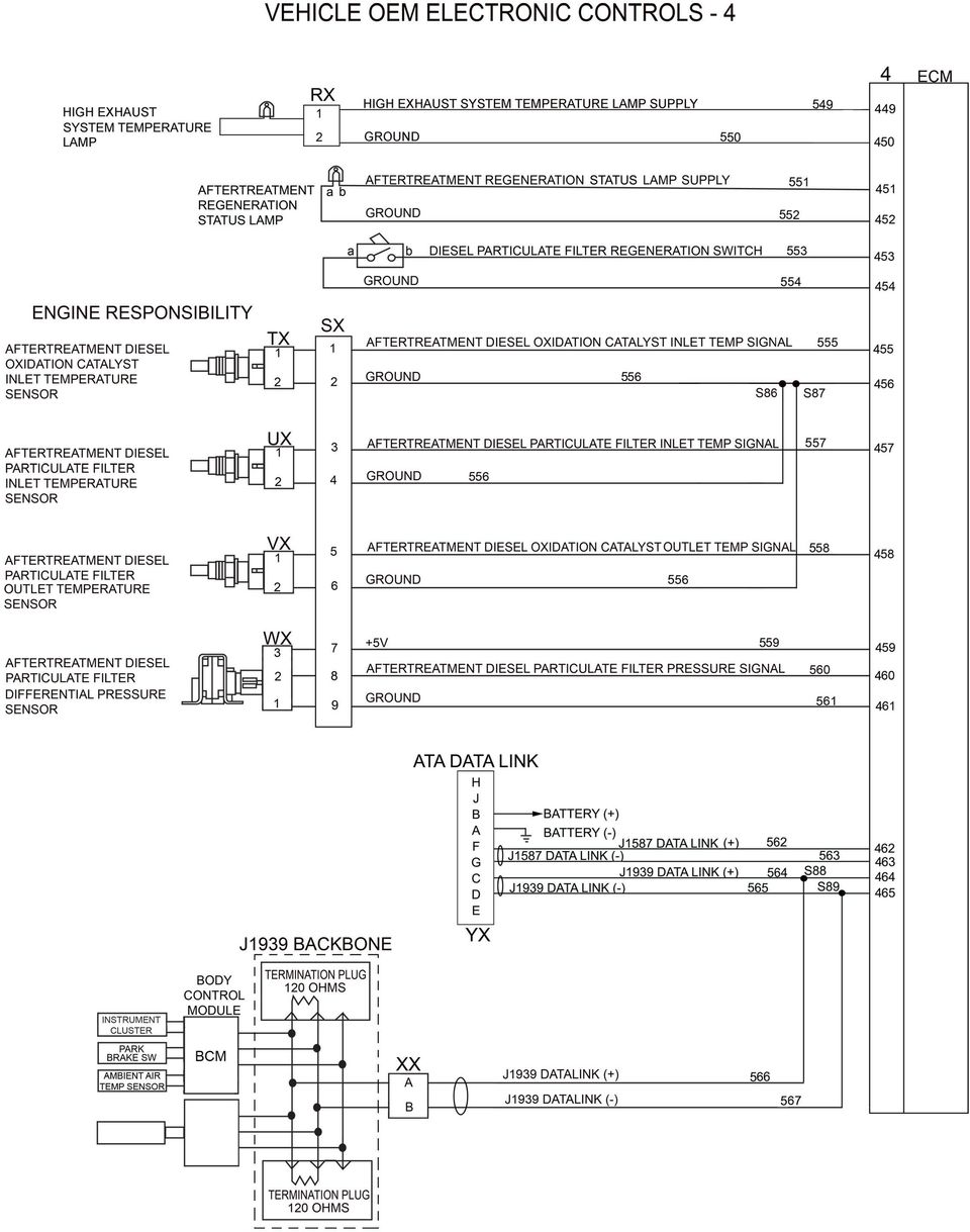
9

10

11

12
13 Idle Shutdown Timer (IST) The idle shutdown feature reduces the amount of fuel burned and increases engine life by shutting down the engine after a period of engine idling with no driver activity. Thirty seconds before the shutdown occurs, the stop engine lamp flashes to alert the driver of an impending shutdown. The driver can override the shutdown by depressing the service brake, clutch, or accelerator pedals during the warning period. If the override is successful, the SEL will continue flashing for two minutes. The idle shutdown time period will restart when the idle condition is detected by the ECM. Idle shutdown can interact with the PTO feature. It can cause the engine to shutdown when in PTO mode. If the idle shutdown percent load threshold is not exceeded, the engine will be shutdown. The following conditions must be set for the idle shutdown timer to activate. Any change to one or more of these conditions will reset or disable the IST. Enable Conditions for IST: Engine is idling below 750 rpm. Vehicle speed is 0 mph. No active vehicle speed sensor diagnostic faults. PTO/Remote PTO is operating below the percent load threshold. (Customer Programmable Parameters) Ambient air temperature is between 40 F and 80 F (CAN message from body control module). (Customer Programmable Parameters) No active inlet air temperature sensor diagnostic faults. Engine coolant temperature is above 140 F. No active engine coolant temperature sensor diagnostic faults. Stationary diesel particulate filter (DPF) regeneration is inactive. Accelerator pedal position is released (at idle). Service brake pedal switch is closed. Clutch pedal switch is closed. Parking brake applied (CAN message from body control module). EXHAUST AFTERTREATMENT High Exhaust System Temperature Lamp (HEST) - The (HEST) lamp is illuminated by the ECM when the exhaust gas temperatures monitored by EGT3 exceed 850 F and vehicle speed is below 5 mph. Aftertreatment Regeneration Status Lamp (DPFR) - The ECM illuminates the aftertreatment regeneration status lamp when DPF restriction reaches set points based on the input from the DPF differential pressure sensor (DPF Delta P). This indicates the need for DPF regeneration based on the following levels: Level 1- Low soot load. The DPFR status lamp is illuminated. Level 2- Moderate soot load. The DPFR status lamp is flashing. Level 3- Full soot load. The DPFR status lamp is flashing and CEL is illuminated. Level 4- Over-full soot load. The DPFR status lamp is flashing and the SEL is illuminated. ASE MEDIUM/HEAVY COMPOSITE VEHICLE TYPE 3 REFERENCE BOOKLET PAGE 12

14 Aftertreatment Fuel Injector (AFI) - Fuel transfer pressure is supplied to the pulse width modulated (PWM) aftertreatment fuel injector from a shutoff valve located on the secondary fuel filter outlet. The ECM injects diesel fuel into the exhaust gas, upstream of the diesel oxidation catalyst (DOC), to raise the temperature. When DOC inlet temperature is 600 F, the ECM begins operating the AFI and the duty cycle is varied until the exhaust temperature increases to the desired level for regeneration. Aftertreatment Fuel Shutoff Valve (AFS) - The AFS controls the fuel flow to the supply valve on the secondary fuel filter housing when commanded by the ECM. After startup and during the first minute of engine operation, the ECM performs a self-test on the system by opening the AFS to pressurize the aftertreatment fuel system. The AFD is then opened to relieve the fuel pressure while the ECM monitors the AFP sensor readings. The ECM will disable active and stationary regeneration until the next key cycle if a problem is detected. Aftertreatment Fuel Drain Valve (AFD) - The AFD valve is used to maintain and relieve the fuel pressure in the aftertreatment fuel system. The ECM commands the AFD to open and allow fuel to flow into the fuel return line. Aftertreatment Regeneration System Operation - The aftertreatment diesel particulate filter accumulates soot and ash during engine operation. Soot is oxidized and removed during regeneration. Ash accumulates in the DPF over the service life of the unit. The DPF needs to be disassembled and the ash is removed by a special cleaning process. Regeneration is passive or active based on engine operating conditions, DPF restriction level, and driver s response requirement. The ECM will not enable active or stationary regeneration if the DPF restriction is at Level 4. Passive regeneration occurs when the exhaust temperatures are high enough through normal engine operation. This typically happens when the vehicle is driven at highway speeds and/or under heavy loads. Active regeneration occurs when the exhaust temperatures are not high enough to oxidize the soot collected in the DPF. This will occur more frequently in vehicles with low speed and low load duty cycles. The ECM will inject diesel fuel into the exhaust gas before the inlet of the diesel oxidation catalyst (DOC) to raise the temperature for regeneration. The ECM will enable and disable active regeneration as needed. The speed threshold for active regeneration to take place is 25 mph and it will stop when the vehicle speed drops below it. The exhaust temperature during active regeneration can reach up to 1,500 F. Stationary (Parked) regeneration is needed when conditions are not reached during vehicle operation. This is a form of active regeneration initiated by the operator using the DPF Regeneration Switch when the vehicle is not moving. The vehicle must be parked with the transmission in NEUTRAL and the parking brake set. There can be no input from the accelerator, brake, and clutch pedals. The ECM controls the regeneration process that can last up to 1 ½ hours depending on the amount of DPF restriction. PAGE 13 ASE MEDIUM/HEAVY COMPOSITE VEHICLE TYPE 3 REFERENCE BOOKLET
 - The AFS controls the fuel flow to the supply valve on the secondary fuel filter housing when commanded by the ECM.")
15 DATA LINK COMMUNICATIONS The SAE J1939 data link bus (controller area network - CAN) allows the ECM to communicate with other vehicle control systems such as transmission, automatic traction control, antilock brake, and body controllers. The J1939 data link is an unshielded twisted pair (UTP). The ECM will broadcast public data link messages when the key switch is in the ON position and stops when the key switch is OFF. The ECM will also broadcast private data link messages to drive actuators using J1939 protocol during engine operation and diagnostic programming. The Society of Automotive Engineers (SAE) recommends a maximum backbone harness of 131 feet (40 meters) in length. The harness is terminated at each end with a 120 ohm resistor. Up to 30 different devices can be attached to the J1939 backbone harness at one time. Each device is connected to the backbone harness with a 3 pin stub connector and can be a maximum of 3.3 feet (1 meter) in length. Any of the following conditions will cause the data communications bus to fail and result in the storage of network DTCs: either data line shorted to power, to ground, or to the other data line. The data bus will remain operational when one of the two modules containing a terminating resistor is not connected to the network. The data bus will fail when both terminating resistors are not connected to the network. Data communication failures do not prevent the ECM from providing fuel management. The Diagnostic Tool communicates with the ECM through the 9 pin ATA connector using J1708 protocols over the J1939 and/or J1587 data links. This allows for diagnostic information retrieval and parameter calibration setting. The 9 pin ATA type data link connector is located in the cab. DIAGNOSTIC TROUBLE CODES (DTC) Trouble codes can be active or inactive. Active codes indicate that the problem currently exists and inactive codes indicate that a problem once existed. Flash codes represent digits assigned to diagnostic trouble codes, so that DTCs can be retrieved through the warning lamps when the diagnostic switch is activated. Active codes are indicated by the red stop engine lamp (SEL). Inactive codes are indicated by the yellow check engine lamp (CEL). When using the diagnostic tool, DTCs are formatted under SAE J1939 standards and descriptions. DIAGNOSTIC EQUIPMENT A breakout tool can be connected into a circuit to measure voltage signals and resistance values with a digital multimeter (DMM). A diagnostic tool can be connected to the data link connector to read engine data, diagnostic codes, and set programmable parameters. ECM software updates (re-flash) can be performed using a PC based diagnostic tool. The Displayed Data chart shows how diagnostic tool data will be presented in some Composite Vehicle test questions. The chart includes how the status of components (switches and lamps) or operational modes will be indicated. The minimum maximum measurement range and values for engine data (voltages, temperatures, pressures, and speeds) is also shown. (Please refer to the chart that follows.) ASE MEDIUM/HEAVY COMPOSITE VEHICLE TYPE 3 REFERENCE BOOKLET PAGE 14

16 DISPLAYED DATA Displayed Data: Value Range: Displayed Data Value Range Aftertreatment Diesel Oxidation ºF Engine Coolant Level Low/Normal Catalyst Inlet Temperature Aftertreatment Diesel Oxidation V Engine Coolant Temperature -40º - 260ºF Catalyst Inlet Temperature Sensor Signal Aftertreatment Diesel Particulate Filter 0 30 inhg Engine Coolant Temperature Sensor V Differential Pressure Signal Aftertreatment Diesel Particulate Filter V Engine Oil Pressure psi Differential Pressure Sensor Signal Aftertreatment Diesel Particulate Filter ºF Engine Oil Pressure Sensor Signal V Inlet Temperature Aftertreatment Diesel Particulate Filter V Engine Oil Temperature -40º - 260ºF Inlet Temperature Sensor Signal Aftertreatment Diesel Particulate Filter On/Off Engine Oil Temperature Sensor Signal V Lamp Status Aftertreatment Diesel Particulate Filter ºF Engine Protection Shutdown On/Off Outlet Temperature Aftertreatment Diesel Particulate Filter V Engine Speed rpm Outlet Temperature Sensor Signal Aftertreatment Diesel Particulate Filter On/Off Exhaust Back Pressure InHg Regeneration Start Switch Status Aftertreatment Fuel Pressure psi Exhaust Back Pressure Sensor Signal V Aftertreatment Fuel Pressure Sensor V Fuel Temperature -40º - 260ºF Signal Aftertreatment High Exhaust System On/Off Fuel Temperature Sensor Signal V Temperature Lamp Status Accelerator Pedal Position 0 100% Inlet Air Temperature -40º - 260ºF Amber/Yellow Check Engine Lamp On/Off Inlet Air Temperature Sensor Signal V Status (CEL) Air Conditioning High Pressure Switch On/Off Intake Manifold Air Temperature -40º - 260ºF Battery 0 18 V Intake Manifold Air Temperature V Sensor Signal Barometric Air Pressure 0 30 inhg Intake Manifold Pressure (Gauge) 0 60 psi Barometric Air Pressure Sensor Signal V Intake Manifold Pressure Sensor V Signal Clutch Pedal Switch Released/Depressed Fan Control Switch On/Off CMP/Engine Position 1 Signal Yes/No Key (Ignition) Switch On/Off CKP/Engine Position 2 Signal Yes/No Outside (Ambient) Air Temperature -40º - 260ºF Crankcase Pressure 0 40 inh20 PTO On/Off Switch On/Off Crankcase Pressure Sensor Signal V PTO Status Active/Inactive Cruise Control On/Off Switch On/Off Red Stop Engine Lamp Status (SEL) On/Off Cruise Control Set/Resume Switch Set/Neutral/Resume Remote PTO Switch On/Off Diagnostic Switch On/Off Sensor Supply V ECM Time (Key On Time) HH:MM:SS Sensor Supply V EGR Differential Pressure 0 30 inhg Sensor Supply V EGR Differential Pressure Sensor V Service Brake Pedal Switch Released/Depressed Signal EGR Temperature 0º ºF Synchronization State Yes/No EGR Temperature Sensor Signal V Transmission Gear Ratio.1-16 EGR Valve Position Measured 0 100% Turbocharger Actuator Position 0-100% (Percent Open) Measured (Percent Closed) EGR Valve Position Sensor Signal V Turbocharger Actuator Position 0-100% Commanded (Percent Closed) Engine Brake On/Off Switch On/Off Turbocharger Speed 0 200,000 rpm Engine Brake Selector Switch Low/Med/High Vehicle Speed mph PAGE 15 ASE MEDIUM/HEAVY COMPOSITE VEHICLE TYPE 3 REFERENCE BOOKLET

17 PROGRAMMABLE PARAMETERS Programmable parameters are the specifications that can be set within the ECM to control operating functions. The parameters are stored in non-volatile memory. A customer password is available for programming protection. A list of parameter ranges and their settings are shown below. Feature Range Setting Feature Range Setting Road Speed Governor PTO/Remote PTO Accelerator Max. Road mph 65 mph Max PTO Speed rpm 1000 rpm Speed Accelerator Upper Droop 0-3 mph 0 mph Min PTO Speed rpm 700 rpm Accelerator Lower Droop 0-3 mph 1 mph Set PTO Speed rpm 900 rpm Global Max. Road Speed mph 120 mph Resume PTO Speed rpm 1000 rpm Gear Down Protection Remote PTO Speed rpm 1000 rpm (GDP) GDP Light Load Vehicle mph 54 mph Max. Engine Load ft.lb. 800 ft.lb. Speed GDP Heavy Load Vehicle mph 60 mph Max. Vehicle Speed 0-30 mph 0 mph Speed Idle Speed Control Ramp Rate rpm/sec 250 rpm/sec Idle Engine Speed rpm 700 rpm Aftertreatment Idle Shutdown Stationary Regeneration in PTO Enabled/Disabled Enabled Idle Shutdown Timer min. 5.0 min. Automatic Stationary Regeneration Enabled/Disabled Enabled Idle Shutdown Lower 0-100ºF 40ºF Mobile/Active Regeneration Enabled/Disabled Enabled Ambient Air Temp. Idle Shutdown Upper 0-100ºF 80ºF Minimum Vehicle Speed mph 25 mph Ambient Air Temperature Override Idle Shutdown 0-100% 100% Diesel Particulate Filter Lamp Enabled/Disabled Enabled Percent PTO Load Override Idle Shutdown Enabled/Disabled Enabled Diesel Particulate Filter Enabled/Disabled Enabled Regeneration Permit Switch Idle Shutdown Manual Enabled/Disabled Enabled Diesel Particulate Filter Enabled/Disabled Enabled Override Regeneration Start Switch Fan Control High Exhaust System Temperature Enabled/Disabled Enabled Lamp Minimum Fan On Time sec. 240 sec. Vehicle Setup Parameters Fan Control Solenoid Logic 0 Volts Rear Axle Ratio ON Fan On During Engine Enabled/Disabled Enabled Tire Size rev/mile 501 Braking Fan Vehicle Speed Enabled/Disabled Enabled No. of Tailshaft Gear Teeth Interaction Fan Control A/C Press Enabled/Disabled Enabled Vehicle Speed Sensor Type Magnetic Switch Fan Control Switch Enabled/Disabled Enabled Max. Engine Speed w/out VSS rpm 1800 rpm Cruise Control/Engine Max. Engine Speed with VSS rpm 2100 rpm Brakes Max. Cruise Control Speed mph 65 mph Trans. Top Gear Ratio Cruise Control Upper Droop 0-3 mph 0 mph Trans. One Gear Down Ratio Cruise Control Lower Droop 0-3 mph 2 mph Transmission Type Manual Cruise Control Speed 0-6 mph 5 mph Multiplexing Ambient Air J1939 Delta for Max. Engine Brake Temperature Sensor Cruise Control Speed mph 3 mph Ambient Air Temperature Source Delta for Min. Engine Brake Address Cruise Control Feature Enabled/Disabled Enabled Multiplexing Parking Brake Switch J1939 Engine Brake Enabled/Disabled Enabled Parking Brake Source Address Cruise Control Activation Engine Brake Min. Vehicle 0-35 mph 0 mph Engine Protection Speed Engine Brake Delay 0-10 sec. 0 sec. Engine Protection Warning/Derate/ Shutdown Shutdown Feature Shutdown Engine Brake Enabled/Disabled Enabled Engine Protect Restart Inhibit Enabled/Disabled Enabled Service Brake Activation Engine Brake Control Enabled/Disabled Enabled Manual Override Enabled/Disabled Enabled ASE MEDIUM/HEAVY COMPOSITE VEHICLE TYPE 3 REFERENCE BOOKLET PAGE 16

18 ENGINE OPERATING SPECIFICATIONS Fuel Supply Pressure Cranking: 20 psi. min. Rated rpm: psi. Engine Oil Pressure Idle: psi. min. Rated rpm: psi. Intake Manifold Pressure Rated rpm: psi. ELECTRICAL SPECIFICATIONS J1587 Data Link Positive Wire to chassis ground: 2.5 to 5.0 VDC Negative Wire to chassis ground: 0.0 to 2.5 VDC J1939 Data Link Positive wire to negative wire 50 to 70 ohms Terminal Resistance 110 to 130 ohms ECM 9.0 to 16.0 VDC supply voltage Maximum voltage drop on all circuits (except injectors): 0.5 VDC ECM 5V-Reference Sensor Supply Groups Circuit Group ECM Pin Numbers Sensor Supply 1 13, 23, 66, 204 Sensor Supply 2 459, 210 Sensor Supply 3 72, 75 5 V Reference Power Supply At ECM: 4.75 to 5.25 VDC At Harness: 4.75 to 5.25 VDC All Shorts to External OK: if less than 1.5 VDC All Shorts to Ground OK: If greater than 100K ohms (No short circuit) All Continuity Checks OK: if less than 10 ohms (No open circuit) Fuel Injectors 0.5 to 5.0 ohms resistance 100 to 120 VDC supply voltage SENSOR SPECIFICATIONS Vehicle Speed Sensor Coil Resistance: 1100 to 1500 ohms Intake Manifold Pressure Sensor Pressure psig inhg. VDC atmospheric atmospheric All Temperature Sensors Resistance: 600 to 1600 ohms Barometric Pressure Sensor Pressure Altitude inhg. feet VDC (sea level) PAGE 17 ASE MEDIUM/HEAVY COMPOSITE VEHICLE TYPE 3 REFERENCE BOOKLET

19 Engine Oil Pressure Sensor Pressure kpa psi VDC All Temperature Sensors (except exhaust aftertreatment and EGR) Temperature C F VDC Aftertreatment Fuel Pressure Sensor Pressure kpa psi VDC Coolant Level Sensor Coolant present: CL Normal signal = 5 VDC, CL Low signal near 0 VDC Coolant NOT present: CL Low signal = 5 VDC, CL Normal signal near 0 VDC Accelerator Pedal Position Sensor Accelerator APP 2 APP 1 Pedal Position Sensor Sensor % depressed EGR Position Sensor EGR Valve (% Open) Sensor All Sensor Signal s Out of Range Low = Less than 0.20 VDC Normal Range = VDC Out of Range High = Greater than 4.80 VDC ASE MEDIUM/HEAVY COMPOSITE VEHICLE TYPE 3 REFERENCE BOOKLET PAGE 18

20 National Institute for AUTOMOTIVE SERVICE EXCELLENCE All rights reserved 101 Blue Seal Dr. S.E., Suite 101, Leesburg, VA ACT Code: PEM Code: AC

Signature and ISX CM870 Electronics
 Signature and ISX CM870 Electronics Cummins West Training Center System Description General Information The Signature and ISX CM870 engine control system is an electronically operated fuel control system
Note: This information obtained from internet sources and not verified- use at your own risk!!!!
 Cummins Engine Diagnostic Fault Codes for 2003 and later engines (generally for 2004 and later Alpines; see page 13 for earlier engine diagnostic codes): Note: This information obtained from internet sources
Diagnostic Trouble Code (DTC) Charts
 Charts") Diagnostic Trouble Code (DTC) Charts Note: Before proceeding to the Pinpoint Test, refer to the Diagnostic Trouble Code (DTC) Descriptions for additional information to assist in diagnosis. 6.0L Diesel
Diagnostic Trouble Code (DTC) Charts Note: Before proceeding to the Pinpoint Test, refer to the Diagnostic Trouble Code (DTC) Descriptions for additional information to assist in diagnosis. 6.0L Diesel
Fault codes DM1. Industrial engines DC09, DC13, DC16. Marine engines DI09, DI13, DI16 INSTALLATION MANUAL. 03:10 Issue 5.0 en-gb 1
 Fault codes DM1 Industrial engines DC09, DC13, DC16 Marine engines DI09, DI13, DI16 03:10 Issue 5.0 en-gb 1 DM1...3 Abbreviations...3 Fault type identifier...3...4 03:10 Issue 5.0 en-gb 2 DM1 DM1 Fault
Service Information Trucks
 Service Information Trucks Group 28 Release2 Engine Control Module (ECM), Diagnostic Trouble Code (DTC), Guide 2010 Emissions CHU CXU GU TD 89047073 Foreword The descriptions and service procedures contained
Diagnostic Fault Codes For Cummins Engines
 Section - Diagnostic Fault Codes For Cummins Engines Applies to Engine Models T, T, QSL T, QSM, QS, QSK9, QSK, QST, QSK//8 Note: These fault codes are current at date of publication. Always refer to engine
The Aftertreatment System Technician's Guide has been revised.
 NUMBER: 2 ATS 07 S.M. REF.: Listed in Table 1 ENGINE: ATS DATE: April 2007 SUBJECT: UPDATES TO AFTERTREATMENT SYSTEM TROUBLESHOOTING PUBLICATION: 7SE63 The Aftertreatment System Technician's Guide has
COMMON RAIL SYSTEM (CRS) SERVICE MANUAL: Operation
 SERVICE MANUAL: Operation") ISUZU ELF 4HK1/4JJ1 Engine COMMON RAIL SYSTEM (CRS) SERVICE MANUAL: Operation Issued : June 2007 Revised : July 2009 00400601EA 2009 DENSO CORPORATION All rights reserved. This material may not be reproduced
ISUZU ELF 4HK1/4JJ1 Engine COMMON RAIL SYSTEM (CRS) SERVICE MANUAL: Operation Issued : June 2007 Revised : July 2009 00400601EA 2009 DENSO CORPORATION All rights reserved. This material may not be reproduced
1 Air-to-Air AfterCooling. 2 Engine Only. Capacity will vary with radiator size and use. of cab heater.
 Diesel Truck Engine 3126B 175-330 hp 420-860 @ 1440 rpm Peak CATERPILLAR ENGINE SPECIFICATIONS 6-Cylinder, 4-Stroke-Cycle Diesel Bore in (mm)... 4.33 (110) Stroke in (mm)... 5.0 (127) Displacement cu in
Electronic Power Control
 Service. Self-Study Programme 210 Electronic Power Control Design and Function With the Electronic Power Control system, the throttle valve is actuated only by an electric motor. This eliminates the need
2015 Programming Guide
 2015 Programming Guide Table of Contents 1.0 Introduction... 4 2.0 References... 4 3.0 How to Read This Document... 4 4.0 Engine Ratings... 7 5.0 General Settings... 10 6.0 Idle Settings... 12 6.1. Engine
Electronic Diesel Control EDC 16
 Service. Self-Study Programme 304 Electronic Diesel Control EDC 16 Design and Function The new EDC 16 engine management system from Bosch has its debut in the V10-TDI- and R5-TDI-engines. Increasing demands
E - THEORY/OPERATION
 E - THEORY/OPERATION 1995 Volvo 850 1995 ENGINE PERFORMANCE Volvo - Theory & Operation 850 INTRODUCTION This article covers basic description and operation of engine performance-related systems and components.
C18 ACERT Fire Pump Tier 3 448 bkw/600 bhp @ 1750 rpm
 CATERPILLAR ENGINE SPECIFICATIONS I-6, 4-Stroke-Cycle Diesel Bore...145.0 mm (5.71 in) Stroke...183.0 mm (7.2 in) Displacement... 18.1 L (1,104.53 in3) Aspiration...Turbocharged Aftercooled Compression
Volvo Vehicle Communications Software Manual
 Volvo Vehicle Communications Software Manual August 2013 EAZ0025B47A Rev. C Trademarks Snap-on is a trademark of Snap-on Incorporated. All other marks are trademarks or registered trademarks of their respective
SAS light Check Engine Malfunction Indicator Lamp
 SAS light Check Engine Malfunction Indicator Lamp Here's how to do it: In car ECM Diagnostics/ECM Reset procedure: 1) Sit in the driver's seat. 2) Turn the ignition key to the ON position and wait three
Trucks. Group 28 Release1. Engine Control Module (ECM), AftertreatmentControlModule (ACM), VMAC IV Diagnostic Trouble Code (DTC)
, AftertreatmentControlModule (ACM), VMAC IV Diagnostic Trouble Code (DTC)") ServiceInformation Trucks Group 28 Release1 Engine Control Module (ECM), AftertreatmentControlModule (ACM), VMAC IV Diagnostic Trouble Code () 89091093 Foreword The descriptions and service procedures
ServiceInformation Trucks Group 28 Release1 Engine Control Module (ECM), AftertreatmentControlModule (ACM), VMAC IV Diagnostic Trouble Code () 89091093 Foreword The descriptions and service procedures
REMOVAL AND INSTALLATION
 303-01C-1 REMOVAL AND INSTALLATION Engine Body On Special Tool(s) Adapter For 303-D043 303-D043-02 or equivalent Special Tool(s) 303-01C-1 Turbocharger Lifting Bracket 303-1266 Wrench, Fan Clutch Nut 303-214
AUTOMATIC TRANSMISSION IN-CAR DIAGNOSTICS
 Learning Guide CHASSIS ELECTRICAL SPECIALIST AUTOMATIC TRANSMISSION IN-CAR DIAGNOSTICS COURSE NUMBER: C050-01 Notice Due to the wide range of vehicles makes and models, the information given during the
Typical ECM/PCM Inputs
 Typical ECM/PCM Inputs The computer system components fall into two categories: sensors (inputs) and controlled components (outputs). Each system has sensors. Not every system has all the ones listed,
V-MAC III Fault Assignments
 V-MAC III Fault Assignments ELECTRICAL FAULTS Stp Circuit Failure Blink Sequence 4 Engine Oil Pressure Low Voltage / Open 1 1 P 100 4 128/143 4 Engine Oil Pressure High Voltage 1 1 P 100 3 128/143 9 Barometric
ON-Board Diagnostic Trouble Codes
 ON-Board Diagnostic Trouble Codes The list below contains standard diagnostic trouble codes (DTC s) that are used by some manufacturers to identify vehicle problems. The codes provide below are generic
Service Manual Trucks
 Service Manual Trucks Group 36 Vehicle Electronic Control Unit (MID 144), Diagnostic Trouble Code (DTC), Guide From build date 1.2007 PV776-88951780 Foreword The descriptions and service procedures contained
Powertrain DTC Summaries EOBD
 Powertrain DTC Summaries Quick Reference Diagnostic Guide Jaguar XJ Range V6, V8 N/A and V8 SC 2003.5 Model Year Refer to pages 2 9 for important information regarding the use of Powertrain DTC Summaries.
DTC Summaries. V8 AJ26 Engine Management 1997. Refer to page 2 for important information regarding the use of this Summary.
 DTC Summaries V8 AJ26 Engine Management 1997 OBD II MONITORING CONDITIONS: When testing for DTC reoccurrence, it can be determined if the Service Drive Cycle was of sufficient length by performing a PDU
ENGINE DIAGNOSTICS & CONTROL
 ENGINE DIAGNOSTICS & CONTROL CONTROL SYSTEM WIRING DIAGRAM Page 1 Page 2 MONITORING SYSTEM AND CONTROL SYSTEM DEVICE RELATIONSHIP CHART : Applicable Component Input Battery Ignition switch A/C switch,
26 3213.13 Diesel Engine Driven Generators Page 1 of 6
 Last Update: December 8, 2014 A. Description of System Consultant s Handbook Page 1 of 6 1. Provide a diesel engine driven electric generating unit, factory assembled, tested and certified to operate at
DTC Database (OBD-II Trouble Codes)
") Auto Consulting S.a.s di Cofano A. & C. Attrezzature diagnostiche Elaborazioni elettroniche Formazione tecnica DTC Database (OBD-II Trouble Codes) Definitions for generic powertrain diagnostic trouble
Auto Consulting S.a.s di Cofano A. & C. Attrezzature diagnostiche Elaborazioni elettroniche Formazione tecnica DTC Database (OBD-II Trouble Codes) Definitions for generic powertrain diagnostic trouble
Technical Service Information
 Technical Service Information COMPLAINT: CAUSE: 1996-20 DEFINITIONS When a VW/Audi vehicle is exhibiting a symptom or is in fail-safe, the technician, in many cases, is unable to communicate with the on-board
Cat Electronic Technician 2015A v1.0 Product Status Report 4/20/2016 2:49 PM
 Page 1 of 19 Cat Electronic Technician 2015A v1.0 Product Status Report 2:49 PM Product Status Report Parameter Value Product ID WRK00337 Equipment ID WRK00337 Comments A01-52 C9 330D (THX37891) Parameter
Lotus Service Notes Section EMR
 ENGINE MANAGEMENT SECTION EMR Sub-Section Page Diagnostic Trouble Code List EMR.1 3 Component Function EMR.2 7 Component Location EMR.3 9 Diagnostic Guide EMR.4 11 CAN Bus Diagnostics; Lotus TechCentre
TOYOTA ELECTRONIC CONTROL TRANSMISSION
 Electronic Control Transmission (ECT) The Electronic Control Transmission is an automatic transmission which uses modern electronic control technologies to control the transmission. The transmission itself,
Perfectly Adapted. ISB Euro 6 Diesel Engines 150-310PS. Cummins Ltd. Address Line One Address Line Two Address Line Three
 Perfectly Adapted ISB Euro 6 Diesel Engines 150-310PS Cummins Ltd. Address Line One Address Line Two Address Line Three Tel: +00 0000 000000 Fax: +00 0000 000000 Internet: cummins.com Bulletin 0000000
A/C-HEATER SYSTEM - AUTOMATIC
 A/C-HEATER SYSTEM - AUTOMATIC 1995 Volvo 850 1995-96 Auto. A/C-Heater Systems Volvo 850 * PLEASE READ THIS FIRST * WARNING: To avoid injury from accidental air bag deployment, read and carefully follow
Introduction to Electronic Signals
 Introduction to Electronic Signals Oscilloscope An oscilloscope displays voltage changes over time. Use an oscilloscope to view analog and digital signals when required during circuit diagnosis. Fig. 6-01
EDGE PRODUCTS EVOLUTION CS and CTS DIESEL POWER LEVELS AND SUPPORTED VEHICLE PARAMETERS (PIDs) [85100 and 85200]
![EDGE PRODUCTS EVOLUTION CS and CTS DIESEL POWER LEVELS AND SUPPORTED VEHICLE PARAMETERS (PIDs) [85100 and 85200]](/thumbs/40/21144514.jpg "EDGE PRODUCTS EVOLUTION CS and CTS DIESEL POWER LEVELS AND SUPPORTED VEHICLE PARAMETERS (PIDs) [85100 and 85200]") EDGE PRODUCTS EVOLUTION CS and CTS DIESEL POWER LEVELS AND SUPPORTED VEHICLE PARAMETERS (PIDs) [85100 and 85200] File date 6/14/2014. For a more up to date listing please visit the manufacturer s website.
EDGE PRODUCTS EVOLUTION CS and CTS DIESEL POWER LEVELS AND SUPPORTED VEHICLE PARAMETERS (PIDs) [85100 and 85200] File date 6/14/2014. For a more up to date listing please visit the manufacturer s website.
Powertrain DTC (P000-P0999) for EOBD Vehicles (Directive 98/69/EC of the European Parliament)
 for EOBD Vehicles (Directive 98/69/EC of the European Parliament)") Powertrain DTC (P000-P0999) for EOBD Vehicles (Directive 98/69/EC of the European Parliament) 1 Trouble Fault location Probable cause code 1 P0000 No fault found - P0001 Fuel volume regulator control -
Powertrain DTC (P000-P0999) for EOBD Vehicles (Directive 98/69/EC of the European Parliament) 1 Trouble Fault location Probable cause code 1 P0000 No fault found - P0001 Fuel volume regulator control -
Electronically Controlled Air Suspension (ECAS) for Trucks
 for Trucks") $2.50 Electronically Controlled Air Suspension (ECAS) for Trucks Maintenance Manual No. 36 Issued 7-99 ECAS System for 6 x 2 and 6 x 4 Vehicles with Rear Air Suspensions Service Notes Service Notes This
$2.50 Electronically Controlled Air Suspension (ECAS) for Trucks Maintenance Manual No. 36 Issued 7-99 ECAS System for 6 x 2 and 6 x 4 Vehicles with Rear Air Suspensions Service Notes Service Notes This
Lotus Service Notes Section EMP
 ENGINE MANAGEMENT SECTION EMP Sub-Section Page Diagnostic Trouble Code List EMP.1 3 'Lotus Scan' Diagnostic Tool EMP.2 43 Engine Management Component Location EMP.3 45 Mechanical Throttle Setting Procedure
Vario Tractors - Fault Codes. Faults. all Vario tractors Tractor / General system. EDC / EMR bus fault. Fault in ECU Programming errors in ECU.
 12/1999 f 1/58 Vario Tractors - Codes 0000 000001 Date Version Page Capitel Index Docu-No. FCT_InitPage 0.0.11 A021; A022 Id rief description Description Consequences Link FENDIAS / Note ECU, EDC; ECU,
Signature and ISX CM870 Fuel System
 Signature and ISX CM870 Fuel System Cummins Ontario Training Center HPI-TP Fuel System Heavy Duty High Pressure Injection - Time Pressure Fuel System The fuel system developed for the Signature and ISX
COVERING MILLIONS Preferred Protection Plan, a Service Group Company www.sgifs.com PO Box 26830, Austin, TX 78755-0800.
 COVERING MILLIONS Preferred Protection Plan, a Service Group Company www.sgifs.com PO Box 26830, Austin, TX 78755-0800. 1-877-565-0816 PPP-308 0903 rev 0408 BENEFITS New and Pre-Owned Vehicles Preferred
Oregon Fuel Injection
 FORD POWERSTROKE DIAGNOSTICS 1994-2003 This guide is not a substitute for the proper diagnostic manuals and a scan tool. It is intended to be used with the proper tools to help diagnose and solve drivability
VEHICLE SPEED CONTROL SYSTEM
 PL VEHICLE SPEED CONTROL SYSTEM 8H - 1 VEHICLE SPEED CONTROL SYSTEM TABLE OF CONTENTS page DESCRIPTION AND SPEED CONTROL SYSTEM...1 SPEED CONTROL SERVO-PCM OUTPUT....2 SPEED CONTROL SWITCHES PCM INPUT...2
Wynn s Extended Care
 Wynn s Extended Care Every car deserves to receive the very best care... especially yours. How Do You Keep Your Reliable Transportation Reliable? Count on Wynn s Because Wynn s has been caring for cars
Section 7. Evaporator thermistor. Under-and-over pressure safety switches. Connections to the ECU
 Automatic Temperature Control Diagnosis and Repair Diagnosis of Automatic A/C Systems The most common automatic A/C system malfunctions tend to be the result of basic air conditioning problems. These problems
The 2.0l FSI engine with 4-valve technology
 Service Training Self-study programme 322 The 2.0l FSI engine with 4-valve technology Design and function The 2.0l engine is based on the tried and tested 827/113 series. Thanks to FSI technology (Fuel
Kobelco Extended Warranty Program. www.kobelco-europe.com
 Kobelco Extended Warranty Program www.kobelco-europe.com Kobelco Extended Warranty is a convenient, value added way to give your Kobelco customers added security and peace of mind. Benefits of the Kobelco
Cat Electronic Technician 2015A v1.0 Product Status Report 6/3/2015 4:41 PM
 Cat Electronic Technician 2015A v1.0 Product Status Report 6/3/2015 4:41 PM Product Status Report Parameter Product ID Equipment ID Comments Value DHK00407 Machine Control 320D/323D (DHK00407) Parameter
Skills Standards MEDIUM/HEAVY DUTY TRUCK: DIESEL ENGINE REPAIR TECHNICIAN OD32151 ALIGNED WITH ASE/NATEF
 Skills Standards MEDIUM/HEAVY DUTY TRUCK: DIESEL ENGINE REPAIR TECHNICIAN OD32151 ALIGNED WITH ASE/NATEF Competency-Based Education: OKLAHOMA S RECIPE FOR SUCCESS BY THE INDUSTRY FOR THE INDUSTRY Oklahoma
US Heavy Duty Fleets - Fuel Economy
 US Heavy Duty Fleets - Fuel Economy Feb. 22, 2006 Anthony Greszler Vice President Advanced Engineering VOLVO POWERTRAIN CORPORATION Drivers for FE in HD Diesel Pending oil shortage Rapid oil price increases
Operating Instructions Display, graphic. Numeric language
 Operating Instructions Display, graphic Numeric language Contents Numeric language, general... 1 Numeric language, general... 1 Display control stalk... 1 Text strings... 1 Stop message... 2 Change language...
INSTRUMENT PANEL. 1995 Volvo 850 DESCRIPTION & OPERATION. 1995-96 ACCESSORIES & EQUIPMENT Volvo Instrument Panels
 INSTRUMENT PANEL 1995 Volvo 850 1995-96 ACCESSORIES & EQUIPMENT Volvo Instrument Panels 850 WARNING: When working around steering column and before performing repairs, disconnect and shield battery ground
ON-BOARD DIAGNOSTICS ZF 6HP26 TRANSMISSION
 ON-BOARD DIAGNOSTICS ZF 6HP26 TRANSMISSION Vehicle Coverage: XK8 from 2003 model year XJ Range from 2003 model year S-Type from 2003 model year Jaguar Cars Revision Date: October 2003 Page 1 of 30 1 Contents
Turbocharger system components, servicing
 21-1 Turbocharger system components, servicing Engine codes: AAZ, 1Z, AHU Observe rules of cleanliness Page 21-10 Turbocharger hoses and lines, connecting Page 21-11 WARNING! Do not re-use any fasteners
Meritor WABCO Pneumatic Antilock Braking System (ABS) 42.22
 42.22") (ABS) 2.22 Troubleshooting WARNING Before testing a vehicle equipped with Automatic Traction Control (ATC) on a dynamometer, the ATC system must be disabled. See Subject 160 for instructions. Activation
(ABS) 2.22 Troubleshooting WARNING Before testing a vehicle equipped with Automatic Traction Control (ATC) on a dynamometer, the ATC system must be disabled. See Subject 160 for instructions. Activation
Automotive Sensor Simulator. Automotive sensor simulator. Operating manual. AutoSim
 Automotive sensor simulator Operating manual AutoSim Contents Introduction.. page 3 Technical specifications.... page 4 Typical application of AutoSim simulator..... page 4 Device appearance... page 5
2004 MY OBD System Operation Summary for 6.0L Diesel Engine
 2004 MY OBD System Operation Summary for 6.0L Diesel Engine Table of Contents Introduction OBD-I and OBD-II...2 OBD-II Systems...2 OBD-I Systems...2 General Description 6.0 DIT V8...3 Misfire Monitor...5
Electrical Systems - IQAN Digital Control System. IQAN Control System Components... 5.1.3
 Section 5.1 Electrical Systems - IQAN Digital Control System IQAN Control System Components........................... 5.1.3 IQAN Operational Description: At Machine Startup.....................................
VOLKSWAGEN POWERTRAIN CONTROL SYSTEMS DIAGNOSTICS ONE
 LEARNING GUIDE POWERTRAIN SPECIALIST VOLKSWAGEN POWERTRAIN CONTROL SYSTEMS DIAGNOSTICS ONE COURSE NUMBER: PT310-01 Notice Due to the wide range of vehicles makes and models, the information given during
Electronically Controlled Clutchless or Variable Drive Compressors
 Electronically Controlled Clutchless or Variable Drive Compressors On many new air conditioning systems, such as Lexus, Cadillac, Chrysler, and others, a new type of compressor has been fitted. There are
PROCEDURES FOR SELF DIAGNOSTICS
 PROCEDURES FOR SELF DIAGNOSTICS Baum Tools Unlimited Inc. March 31, 1999 TAU 2.1 READING ACTUAL VALUES 1. Remove the operating console from the TAU 2. At the upper side of the operating consol there is
Cat Electronic Technician 2015C v1.0 Product Status Report 2/16/2016 9:19 AM
 Cat Electronic Technician 2015C v1.0 Product Report 2/16/2016 9:19 AM Product Report Product ID Comments Unavailable H2A00626 3054 M313C (CRX13565) H2A00626 Engine Serial Number CRX13565 ECM Serial Number
4000 Series 4008TAG2A Diesel Engine ElectropaK 947 kwm @ 1500 rpm
 The Perkins 4000 Series family of 6, 8, 12 and 16 cylinder diesel engines was designed in advance of today s uncompromising demands within the power generation industry and includes superior performance
Transmission electronic controls outline. Inputs- processing- outputs
 Transmission electronic controls outline Inputs- processing- outputs Inputs provide the system the environmental conditions that are needed to operate or check the operation of the transmission. Inputs
Transporter Current Flow Diagram No. 80 / 1
 Transporter Current Flow Diagram No. 80 / 1 2.5 l/65 kw direct injection turbo diesel, engine code AJT From May 1999 2.5 l/75 kw direct injection turbo diesel, engine codes ACV, AUF 2.5 l/111 kw direct
6-years/75,000 miles Comprehensive coverage Subsequent Owner Warranty $100 Deductible
 LINCOLN PREMIER LIMITED WARRANTY 6-years/75,000 miles Comprehensive coverage Subsequent Owner Warranty $100 Deductible Comprehensive Coverage Because Lincoln has always been a brand you can trust and respect,
2001 MY OBD System Operation Summary for 7.3L Diesel Engine
 2001 MY OBD System Operation Summary for 7.3L Diesel Engine Table of Contents Introduction OBD-I and OBD-II... 2 OBD-II Systems...2 OBD-I Systems...2 Misfire Monitor... 3 Low Data Rate System...3 Misfire
Cat Electronic Technician 2015C v1.0 Product Status Report 2/20/2016 4:34 PM
 Cat Electronic Technician 2015C v1.0 Product Status Report 2/20/2016 4:34 PM Product Status Report Parameter Product ID Equipment ID Comments Value JGB00714 NOT PROGRAMMED Machine Control 345D (JGB00714)
Overview. Technical Training
 Overview Diesel particulate are typically soot particles with adherent hydrocarbons, sulphate and other condensed compounds. Legally a particulate is anything in the exhaust stream that can be captured
Subaru Reference. This reference contains the following information: connector pinouts. connector pinouts
 Subject: Source: 1993 2010 Impreza, WRX, and Sti and 2002 07 Outback Sport ABS wiring diagrams, harness routing, and connector locations and pinouts Subaru service manuals This reference contains the following
DIAGNOSIS SYSTEM (3S GTE and 5S FE)
") Diagnosis System (3SGTE and 5SFE) FI39 DIAGNOSIS SYSTEM (3SGTE and 5SFE) DESCRIPTION The ECM contains a builtin, selfdiagnosis system by which troubles with the engine signal network are detected and a
Diagnosis System (3SGTE and 5SFE) FI39 DIAGNOSIS SYSTEM (3SGTE and 5SFE) DESCRIPTION The ECM contains a builtin, selfdiagnosis system by which troubles with the engine signal network are detected and a
Chapter 19 - Common Rail High Pressure Fuel Injection Systems
 Chapter 19 - Common Rail High Pressure Fuel Injection Systems Diesel Engine Technology For Automotive Technicians Understanding & Servicing Contemporary Clean Diesel Technology What is Common Rail? Common
Cummins Westport, Inc. Engine Overview. March 2015
 Cummins Westport, Inc. Engine Overview March 2015 Cummins Westport Inc. (CWI) A Cummins JV Company CWI was established in 2001 as a 50/50 joint venture company between Cummins Inc and Westport Innovations.
Emission Control Systems Warranties
 2004 Chevrolet TrailBlazer - 2WD Emission Control Systems Warranties This section outlines the emission warranties that General Motors provides for your vehicle in accordance with the U.S. Federal Clean
Important: Always perform the Diagnostic System Check - Vehicle prior to using this diagnostic procedure. P0106, P0107 P0107
 Page 1 of 5 DTC P0106 DTC Descriptor 2006 Pontiac GTO GTO (VIN V) Service Manual Document ID: 1417869 DTC P0106: Manifold Absolute Pressure (MAP) Sensor Diagnostic Fault Information Important: Always perform
Air conditioning, electrical testing
 just a test. Air conditioning, electrical testing 01-253 Wire and component test using VAG1598 A test box Special tools and equipment VAG 1598 A test box and VAG 1598/11 adapter cable and VAG 1598/12 VAG1526
3516 Industrial Engine
 CAT ENGINE SPECIFICATIONS V-16, 4-Stroke-Cycle Diesel Bore...170.0 mm (6.69 in) Stroke...190.0 mm (7.48 in) Displacement... 69.06 L (4,214.3 in 3 ) Aspiration...Turbocharged / Aftercooled Compression Ratio...13.0:1
EMR 3 CAN BUS specification
 EMR 3 CAN BUS specification Version 11-3 Overview 1. SAE J1939-Standard CAN Messages... 3 1.1. EEC1:... 3 1.2. EEC2:... 5 1.3. Engine Temperature:... 6 1.4. Engine Fluid Level / Pressure:... 7 1.5. Inlet
CONTINUOUSLY VARIABLE TRANSMISSION (CVT)
") GROUP 23 CONTINUOUSLY VARIABLE TRANSMISSION (CVT) CONTENTS CVT........................... 23-2 GENERAL INFORMATION............. 23-2 ELECTRONIC CONTROL SYSTEM...... 23-3 EEPROM...........................
GROUP 23 CONTINUOUSLY VARIABLE TRANSMISSION (CVT) CONTENTS CVT........................... 23-2 GENERAL INFORMATION............. 23-2 ELECTRONIC CONTROL SYSTEM...... 23-3 EEPROM...........................
Operation Fenix/Renix 35
 Operation Fenix/Renix 35 Foreword The Multi-Tester plus/pro software cassette is the component that gives the diagnostic equipment its unique test characteristics: all data required to make the test system
Annex-A TECHNICAL SPECIFICATION
 Annex-A TECHNICAL SPECIFICATION FOR SUPPLY, INSTALLATION, TESTING AND COMMISSIONING OF 0.4kV (2,000kVA) DIESEL GENERATOR 1 1.0 SCOPE This specification covers the requirements of design, manufacture, delivery
Perfectly Adapted. ISL Euro 6 Gas Engine 250-320PS
 Perfectly Adapted ISL Euro 6 Gas Engine 250-320PS Cummins ISL-G The ISL G is the natural choice in alternative-fuel engine technology. With industry leading performance, it combines all the advantages
Evaporative emissions system
 just a test. Evaporative emissions system 20-48 Function description of EVAP canister system Depending upon the air pressure and ambient temperature, fuel vapor will form above the level of fuel in the
ENGINE CONTROLS AND FUEL SYSTEMS
 ENGINE CONTROLS AND FUEL SYSTEMS Fall 2003 In this special edition of Tech Tips, we will address some of the questions that technicians ask most frequently regarding computer relearn procedures when they
LAND ROVER FUEL INJECTION SYSTEMS
 LAND ROVER FUEL INJECTION SYSTEMS INTRODUCTION Land Rover vehicles use one of two types of electronically controlled fuel injection systems: Multiport Fuel Injection (MFI) or Sequential Multiport Fuel
Diesel Turbo Direct Injection (TDI) system, servicing
 system, servicing") 23-1 Diesel Turbo Direct Injection (TDI) system, servicing The Diesel Direct Fuel Injection (DFI) Engine Control Module (ECM) is equipped with Diagnostic Trouble Code (DTC) memory. Before starting repairs,
23-1 Diesel Turbo Direct Injection (TDI) system, servicing The Diesel Direct Fuel Injection (DFI) Engine Control Module (ECM) is equipped with Diagnostic Trouble Code (DTC) memory. Before starting repairs,
Operational Overview and Controls Guide
 DOCUMENT: ECSEQ2-1 EFFECTIVE: 02/14/07 SUPERSEDES: 02/26/03 Operational Overview and Controls Guide Standard Two or Three Pump Type VFD Booster Controls 6700 Best Friend Road. Norcross, GA 30071. (770)
Table of Contents. 1.what is OBD2. 2. Product Information. 1. Safety Precautions and Warnings 1. obd2 was developed by the Califrnia Air Resources
 Table of Contents 1. Safety Precautions and Warnings 1 2. General Information 2.1 On-Board-Diagnostics (OBD )II 2 2.2 Diagnostic Trouble Codes (DTCs) 2 2.3 Location of the Data Link Connector (DTC) 3 2.4
DTC P1271/78 FUEL PRESSURE REGULATOR CIRCUIT MALFUNCTION (OPEN/SHORT) DTC P1272/78 FUEL PRESSURE REGULATOR SYSTEM MALFUNCTION
 DTC P1272/78 FUEL PRESSURE REGULATOR SYSTEM MALFUNCTION") 05 596 DIAGNOSTICS ECD SYSTEM (1KD FTV)(From August, 2004) DTC P1271/78 FUEL PRESSURE REGULATOR CIRCUIT MALFUNCTION (OPEN/SHORT) 05NJ6 01 DTC P1272/78 FUEL PRESSURE REGULATOR SYSTEM MALFUNCTION For more
05 596 DIAGNOSTICS ECD SYSTEM (1KD FTV)(From August, 2004) DTC P1271/78 FUEL PRESSURE REGULATOR CIRCUIT MALFUNCTION (OPEN/SHORT) 05NJ6 01 DTC P1272/78 FUEL PRESSURE REGULATOR SYSTEM MALFUNCTION For more
ELECTRICAL WIRING (R.H. DRIVE VEHICLES)
") C-1 ELECTRICAL WIRING (R.H. DRIVE VEHICLES) CONTENTS GENERAL.......................... 3 WIRING HARNESS CONFIGURATION DIAGRAMS......................... 4 ENGINE COMPARTMENT................ 4 DASH PANEL...........................
C-1 ELECTRICAL WIRING (R.H. DRIVE VEHICLES) CONTENTS GENERAL.......................... 3 WIRING HARNESS CONFIGURATION DIAGRAMS......................... 4 ENGINE COMPARTMENT................ 4 DASH PANEL...........................
Information and Instructions
 Information and Instructions This shop manual contains several sections each covering a specific group of wheel type tractors. The Tab Index on the preceding page can be used to locate the section pertaining
volvo power D16/D13/D11 powertrain - product tour
 volvo power power D16/D13/D11 powertrain - product tour Overview The new series of Volvo Power engines represents a giant step forward in terms of fuel efficiency, emissions compliance and driver convenience.
TOYOTA ELECTRONIC TRANSMISSION CHECKS & DIAGNOSIS
 Checks and Adjustments The transmission requires regular maintenance intervals if it is to continue to operate without failure. As we discussed in previous sections, transmission fluid loses certain properties
Fixed Right First Time. Volvo Technicians, Service and Parts Managers
 Tech-Net Notes Fixed Right First Time Volvo Technicians, Service and Parts Managers NO: 25-149-A DATE: 04-03-06 MODEL/YEAR: C70 1999-2002 S70 1999-2000 S60 2001 all engine variants, 2002 non-turbo only.
Heater and Air Conditioner, Blend Air System, Troubleshooting 83.06
 A/C Performance Diagnosis Problem Warm Airflow When the Air Conditioner is On, A/C Not Working, or Poor A/C Performance (dash outlet temperature is too high) Problem Warm Airflow When the Air Conditioner
01-3 0000-00 6810-20 AIR CONDITIONING SYSTEM 1. FFH SPECIFICATION AIR CONDITIONING SYSTEM RODIUS 2004.09
 0000-00 01-3 6810-20 1. FFH SPECIFICATION 01-4 0000-00 2. SYSTEM LAYOUT AND COMPONENTS 0000-00 01-5 01-6 0000-00 3. FFH GENERAL INFORMATION The system is to increase the coolant temperature quickly by
COOLING SYSTEM Section Page
 5 COOLING SYSTEM Section Page 5.1 COOLANT PRE-HEATER... 5-3 5.2 COOLANT PUMP NON-EGR ENGINE... 5-7 5.3 COOLANT PUMP EGR ENGINE... 5-13 5.4 FRONT CONNECTOR HOUSING NON-EGR ENGINE... 5-17 5.5 FRONT CONNECTOR
A P P L I C A T I O N A N D I N S T A L L A T I O N G U I D E DIESEL ENGINE CONTROL SYSTEMS
 A P P L I C A T I O N A N D I N S T A L L A T I O N G U I D E DIESEL ENGINE CONTROL SYSTEMS Contents Diesel Engine Control Systems... 1 Engine Protection & Monitoring System Parameters...2 Engine Lubrication
THERMO KING TRUCK & TRAILER UNIT ALARM CODES THIS DOCUMENT SHOWS ALL CURRENT ALARM CODES FOR THERMO KING TRUCK AND TRAILER UNITS.
 THERMO KING TRUCK & TRAILER UNIT ALARM CODES THIS DOCUMENT SHOWS ALL CURRENT ALARM CODES FOR THERMO KING TRUCK AND TRAILER UNITS. NOT ALL CODES ARE POSSIBLE ON ANY INDIVIDUAL UNIT. IF THE ALARM APPLIES