Fast Track Troubleshooting
|
|
|
- June Russell
- 7 years ago
- Views:
Transcription


1 Model: FX510BGS/XAA FX710BGS/XAA WARNING Fast Track Troubleshooting IMPORTANT SAFETY NOTICE For Technicians Only This service data sheet is intended for use by persons having electrical, electronic, and mechanical experience and knowledge at a level generally considered acceptable in the appliance repair trade. Any attempt to repair a major appliance may result in personal injury and property damage. The manufacturer or seller cannot be responsible, nor assume any liability for injury or damage of any kind arising from the use of this data sheet. WARNING Publication # tsfxx10 Revision Date 12/2/2011 CAUTION Disconnect power before servicing the range. Replace all panels before operating range. Failure to do so can result in death or electrical shock. EXPLOSION, FIRE, AND ASPHYXIATION HAZARD Shut off gas supply to the range before servicing. Check all gas lines and fittings for leaks before operating the range. Replace all panels before operating range. Failure to do so can result in death or personal injury from explosion, fire, or asphyxiation. When you work on the gas range, be careful when handling sheet metal parts. Sharp edges may be present, and you can cut yourself if you are not careful. Operation Notes: Convection Fan Operation - During normal Oven operation, the Convection Fan for both the FX510 and the FX710 will cycle on and off. The on time is ~ 10 secs. The off time will vary from ~ 40 to 60 secs. This is normal operation and does not require any service action. Checking Error Codes: There are two kinds of error codes. One denotes an oven temperature sensor error and the other denotes a safety error. Possible error codes during use can be checked before service. 1. Press Clock pad to select AM or PM. Each time the pad is pressed, the display toggles to the other setting. The default setting is PM 2. Press the number pads 1,2,3 and 4. Make sure the Kitchen Timer and Warming Drawer are both turned OFF. 3. Press the Start pad. 4. Press the Custom Cook and the 0 number pads at the same time for 2 seconds. Error codes are displayed. 5. Press the 0 number pad, to display the latest 5 error codes. If the power is interrupted and the oven turns off, the stored error codes are deleted. 6. Press the Clear/Off pad to return to normal display mode. Gas Range Components Components Oven Elements Door Lock Mtr 120vac 1750 ~ 1850Ω Component Voltage Current Room Temp Conv Fan 120vac 20 ~ 30Ω Broil H S I 120vac A 40 ~ 400Ω Sub Fan 120vac 85 ~ 100Ω Bake H S I 120vac A 40 ~ 400Ω Oven Temp Sensor Resistance Chart (FX710BGS/XAA ONLY) Degree ºF Ω Degree ºF Ω Convect 240vac 800 W 70 ~ 73Ω Warm Dr 120vac 600 W 22 ~ 25Ω SUPPORT INFORMATION Training Plus One

2 Not Present on FX510
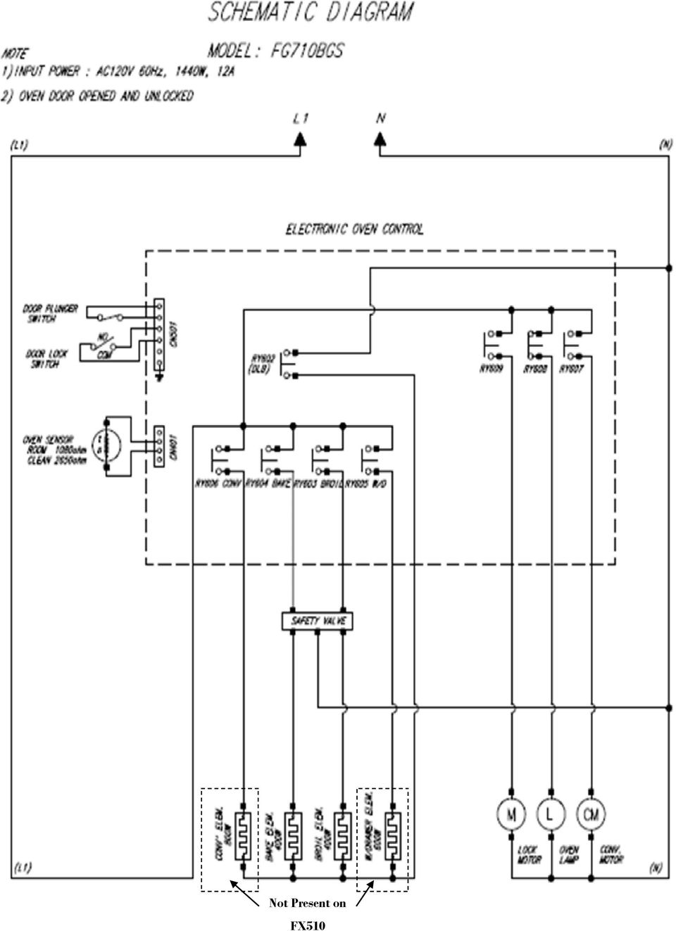
3 FX-710 Control PCB CN301, Membrane Keypad Connector CN101 Power Connector CN401, Oven Sensor 120VAC(L1-N) CN601 Relay Connector Convection Fan Motor Door Lock Motor CN501 Door and Door Lock switches Connector TC601, 603 L1 120VAC Terminal TC602, N Terminal Oven Lamp T607, Conv. Heat Relay T606, W/Drawer Relay T604, Broil ingnitor Relay T605, Bake Ingnitor Relay FX-510 Control PCB CN101 Power Connector CN301, Membrane Keypad Connector CN601 Relay Connector Convection Fan Motor Door Lock Motor Oven Lamp 120VAC(L1-N) CN401, Oven Sensor CN501 Door and Door Lock switches Connector TC601, 603 L1 120VAC Terminal TC602, N Terminal T604, Broil ingnitor Relay T605, Bake Ingnitor Relay
 CN401, Oven Sensor CN501 Door and Door Lock switches Connector TC601, 603 L1 120VAC Terminal TC602,")
, two orifices of different sizes. The FX510 does not have the dual burner. All orifices must be replaced with the proper size orifice.")

4 Natural Gas to LP Conversion : The natural gas to LP conversion kit that is included with the range contains an orifice for the oven bake and broil burners, each of the surface burners and in the case of the FX710 that has a dual burner (right front), two orifices of different sizes. The FX510 does not have the dual burner. All orifices must be replaced with the proper size orifice. Each is stamped with the size and is color coded. The color on the orifice corresponds with the color of the gas valve that controls the burners and the face of the orifice is stamped with the color as well. After replacing the surface burner orifices, there are no adjustments necessary to the burners. If the burner flame is not correct, too high or too low, after verifying the correct orifice is installed the gas valve can be adjusted. Main Gas Valve Conversion: FX710 Natural Gas to LP Gas Conversion Kit supplied with the range (FX510 similar) The LP conversion requires this regulator to be set for different pressures as LP gas is operated at higher pressures than natural gas. From inside the warming / storage drawer reach in and open the red cap on the regulator. Using a 5/8 socket, open end wrench or adjustable wrench, remove the LP regulator stud and set it to the correct position. The default position of the regulator is set for natural gas. To convert to LP remove the brass regulator using a 5/8 wrench or socket and turn it upside down Oven Burner Adjustment. To adjust the shutter, loosen the locking screw and rotate the shutter towards the open or closed position as needed. If flames are lifting off the burner ports, gradually reduce the air shutter opening until the flames are stabilized. If flames are too yellow and/or too large, gradually increase the air shutter opening until the flames have approximately a 1-in blue cone. If the range is set up for natural gas, the flames should burn with no yellow tipping. If the range is set up for LP gas, small yellow tips at the end of the cones are normal. After the flames are adjusted properly, shut off the oven, retighten the locking screws, replace the oven bottom and racks.

5 Samsung 'Gas Range' Diagnostic Code Quick Guide Display Failure Codes POWER LOSS CLEARS CODES 1)Press Clock AM/PM pad. 2) Press pad again, select AM. 3)Press # pads. 4)Press the Start pad. 5)Press Custom Cook & # 0 pads simultaneously for 2 seconds. 6) error codes will display. 7) Press number 0 pad to review last 5 codes. 8) Press Clear/Off to exit. Failure Code Cause Solution E27 E28 Oven sensor opened (over 2950Ω) Oven sensor shorted (Under 930Ω) 1. Disconnect power. Remove the upper rear cover. Disconnect sensor harness from control Measure sensor resistance :1080Ω at room temperature If different value, replace oven sensor. 2. If there is not any problem with oven sensor, Please check whether there is a damaged terminal or wire on harness. 3. Check resistance of oven sensor connector on main PCB (Normal:2850Ω) E-08 E-0A Oven not heating error Oven over heating error 1. Disconnect power. Open the back cover. Disconnect the two harness connectors to the oven temperature sensor. Measure sensor resistance :1080Ω at the room temperature If different value, replace oven sensor. 2. Check the broil, bake and convection heater. Check the resistance of each. 3. Check whether DLB of sub PCB, Broil, Bake and Convection heater relay are being activated 4. Check wiring harnesses between main PCB. 5. Check the resistance of oven sensor connector on main PCB. (Normal : 2850Ω) SE Shorted key 1. Check if cable of keypad has been inserted into connector of main PCB. 2. Check for short between main PCB and connector or keypad and cable. 3. If there is not a problem with connector on main PCB and cable of keypad, replace the main PCB. E-OE Door locking error 1, Press and hold Cook Time & Delay Start for 3 seconds to test motor operation. 2. Disconnect power. Open the back cover. Check wiring harness connections between door lock switch and motor. 3. Check resistance of door lock motor,1750~1850ω at the room temperature. 4. With operating door lockout, measure voltage at door lock motor. (Normal Voltage : AC 120V) 5. Check whether door locking switch is operating properly. 6. Measure resistance CN501 on PCB. (COM-NO: at the room temperature) *COM : Yellow Wire *NO : White Wire E-53 EEPROM error Replace PCB

6 Non Error Code Troubleshooting Failure Cause Solution Warming drawer heater is not working. (FX710 Only Convection fan not working Measure the resistance of the warming drawer heating element. Normal: ~24Ω Check the warming drawer terminal on the main board and the element (T606) Check the warming drawer relay (RY605) on the PCB. Measure the voltage to the heating element Normal: 120VAC Measure the resistance of the convection fan motor. Normal: ~26 Ω Measure the voltage to the fan motor Normal: 120VAC Check the connections to the fan motor Check the fan relay (RY607) on the main board. Replace the warming drawer heater Clean connections Replace the main Board Replace the fan motor Clean connections Replace the main board Convection heater not working (FX710 only) None of the surface burners will light Measure the resistance of the convection heating element Normal: ~18 Ω Measure the voltage to the heater Normal: 120VAC Check the connections to the heater and the main board (T607) Check the heater relay (RY606) on the main board. Check the gas supply to the range Check for burner spark Check the igniter switch connection at the spark module Replace the warming drawer heater Clean connections Replace the main board Open the gas valve to the range Check the igniter switches Turn the gas off and disconnect the electric to the range. Turn the igniter switches one by one to the 11:00 position to simulate Lite and measure the resistance of the switches at the spark module. Normal: 0Ω (only in this position) Check the spark module Only one of the surface burners will not light All surface burners will light but will not stay lit Because of the placement of the orifice, even though the burner cup is protected, it is possible for spillage to get into the cup and block the nozzle Check for crimped or restricted gas lines to the surface burner manifold Check the main gas supply valve is turned on completely Check the LP converter in the regulator to make sure it is in the correct position Clean or replace the orifice with the correct Size.
 on the main board.")
7 Oven Temperature Errors Failure Cause Solution Burner will not light Burner will light but not stay lit Using the Bake or Broil function the oven does not seem to be heating (The measured temperature in the oven does not match the display) Check the HSI (Igniter) Check the wiring to the HSI Check the connections to the safety valve Check that the safety valve is wired Check the connections to the safety valve Check that the safety valve is wired Check that the burners have the correct orifice size for the gas being used Check the air adjustments for proper flame Check that the regulator has the correct position of the LP converter Check the connections to the temperature sensor Check the resistance of the temperature sensor Check for any stored errors Check that the burners have the correct orifice size for the gas being used Check the air adjustments for proper flame Check that the regulator has the correct position of the LP converter Replace the Igniter Reseat or repair the wiring Wire the safety valve Reseat or repair the wiring Wire the safety valve Place the regulator LP converter in the correct position for the gas being used Reseat or repair the wiring Check that the burners have the correct size orifice for the gas being used. Place the regulator LP converter in the correct position for the gas being used Note: If the temperature is more that 15 degrees off from the display, it is possible that the temperature sensor has changed value. If the sensor changes value the oven display will be set to the desired temperature but the actual temperature in the oven cavity will be different. If the temperature in the oven compartment is slightly off the user has the ability to offset the temperature ±30 degrees as outlined in the owner's manual. More than that, suspect a sensor that has changed but is not bad enough to display an error. The hot surface igniter will not come on: Check the igniter with a meter, you should have continuity through the HSI. If open replace the HSI. HSI s do weaken and will eventually generate less heat than they normally could. When this happens they can still allow marginally correct current to flow to the oven gas valve for it to open but not get quite hot enough to ignite the gas burner immediately. When this happens, gas released into the oven can sometimes build up to the point where when finally ignited, the amount of gas lit can cause a small explosion inside the oven or cause an odor of gas without the oven working

Gas Oven Repair Guide
 - /6 - Gas Oven Repair Guide [ FX70*, FX50*] Ver. Aug-0 Ignition Failure Cooktop ignition Oven ignition Heating defect Oven Cooktop Abnormal Flame Button, Motors Lamp Others Smell, Smoke, Noise No Display,
Appliance Diagnostic Modes Microwave. GE Consumer & Industrial Technical Training
 Appliance Diagnostic Modes Microwave GE Consumer & Industrial Technical Training Range Table of Contents General Microwave JVM230/240/250B Series (#31-20100) JVM2070 Series (#31-9111) ZMC3000B Series (#31-1461)
Your safety and the safety of others are very important.
 NATURAL GAS TO PROPANE CONVERSION KIT 090 INSTALLATION INSTRUCTIONS FOR ALTITUDES 0 -,00 FT. ONLY PROPANE CONVERSION KIT SAFETY... INSTALLATION REQUIREMENTS... Tools and Parts... LP Gas Requirements...
Heat Surge Model X5C Fire Place Insert Service Manual Applies to all units w/30000208 circuit board
 Heat Surge Model X5C Fire Place Insert Service Manual Applies to all units w/30000208 circuit board 2012 HS M4417A BR16597R-1 HEAT SURGE 8000 FREEDOM AVE, N. CANTON, OH 44720 330-244-8161 WWW.HEATSURGE.COM
G670 Intermittent Pilot Ignition Controls
 Installation Sheets Manual 121 Gas Combustion Combination Controls and Systems Section G Technical Bulletin Issue Date 0300 Intermittent Pilot Ignition Controls Figure 1: Intermittent Pilot Ignition Control
SIMPLE ELECTRONIC IGNITION WIRE DIAGRAM THERMOSTAT (3) PV PILOT BURNER/IGNITOR - SENSOR Q345A (9) SPARK (4) GND (BURNER) CHASSIS GND
 PV PILOT BURNER/IGNITOR - SENSOR Q345A (9) SPARK (4) GND (BURNER) CHASSIS GND") Honeywell Electronic Ignition Troubleshooting Tech Tip April 2007 The Honeywell S8610H Intermittent Pilot Module provides the ignition sequencing, pilot spark, pilot flame monitoring, Pilot Valve (PV)
Honeywell Electronic Ignition Troubleshooting Tech Tip April 2007 The Honeywell S8610H Intermittent Pilot Module provides the ignition sequencing, pilot spark, pilot flame monitoring, Pilot Valve (PV)
Digi-Motor Installation Guide
 Digi-Motor Installation Guide Installation Video...located at marsdelivers.com Digi-Motor Installation Guide Digi-Motor For technical assistance with your Azure Digi-Motor, call the MARS technical support
OASIS SERVICE & TROUBLESHOOTING MANUAL (WITH DM10 OR DM12)
") OASIS SERVICE & TROUBLESHOOTING MANUAL (WITH DM10 OR DM12) Revision 1.0 Page 1 of 50 THE INFORMATION CONTAINED IN THIS DOCUMENT IS THE SOLE PROPERTY OF INTERNATIONAL THERMAL RESEARCH, LTD. ANY REPRODUCTION
OASIS SERVICE & TROUBLESHOOTING MANUAL (WITH DM10 OR DM12) Revision 1.0 Page 1 of 50 THE INFORMATION CONTAINED IN THIS DOCUMENT IS THE SOLE PROPERTY OF INTERNATIONAL THERMAL RESEARCH, LTD. ANY REPRODUCTION
TECHNICAL SERVICE DEPARTMENT Technical Service Bulletin 1-800-432-8373. Tankless Electric (RTE) Troubleshooting
 Troubleshooting") Sequence of Operations 1 Power supply and field wiring block 2 Energy Cut Off (ECO) 3 Water flow plunger and cold inlet 4 Magnetic flow switch 5 Water temperature thermistor 6 Control panel and circuit
Sequence of Operations 1 Power supply and field wiring block 2 Energy Cut Off (ECO) 3 Water flow plunger and cold inlet 4 Magnetic flow switch 5 Water temperature thermistor 6 Control panel and circuit
Cleaning Instructions, Pilot Replacement and Valve Change. Model No.: 233010 Natural Gas
 Cleaning Instructions, Pilot Replacement and Valve Change Model No.: 233010 Natural Gas 8mm open-end wrench 9mm open-end wrench 10mm open-end wrench 12mm open-end wrench 13mm open-end wrench Phillips screw
B/S/H/ Error codes and service programmes PH
 1 ERROR CODES AND APPLIANCE MESSAGES... 3 1.1 Complete overview of all error codes (in order)... 3 Automatic switch-off... 3 Display is dark and any individual LEDs are lit... 3 E 005... 3 E 011... 3 E
EVANS ELECTRONIC TEMPERATURE CONTROL TROUBLESHOOTING GUIDE for systems equipped with electric coolant valve and external PC board.
 EVANS ELECTRONIC TEMPERATURE CONTROL TROUBLESHOOTING GUIDE for systems equipped with electric coolant valve and external PC board. This Troubleshooting Guide covers the electric coolant valve and control
http://waterheatertimer.org/how-to-troubleshoot-gas-water-heater.html
 http://waterheatertimer.org/how-to-troubleshoot-gas-water-heater.html TECHNICAL SERVICE DEPARTMENT Effective October 2007, we transitioned to the White Rodgers (Intelli-Vent TM )Thermostat Control for
Operator: Save these instructions for future use!
 WHITE-RODGERS 36C01 Combination Gas Valves (24 Volt and 120 Volt Models) INSTALLATI INSTRUCTIS FAILURE TO READ AND FOLLOW ALL INSTRUCTIS CAREFULLY BEFORE INSTALLING OR OPERATING THIS CTROL COULD CAUSE
Propane Conversion Kit PROPANE CONVERSION KIT INSTALLATION MANUAL
 Propane Conversion Kit Supersedes: 145.25-IOM2 (708) Form 145.25-IOM2 (908) PROPANE CONVERSION KIT INSTALLATION MANUAL "LPKIT " - PROPANE CONVERSION KIT Kits are available for field conversion from natural
THC 85 INDUSTRIAL / COMMERCIAL SPACE HEATER
 THC 85 INDUSTRIAL / COMMERCIAL SPACE HEATER Certified to / Certifié à CGA 2.14 M2000 Conforms to / Conforme à ANSI std Z83.7 2000 Suitable for indoor or outdoor installation / Unvented / Unattended Type
36G22, 36G23, 36G24 & 36G52 36J22, 36J23, 36J24 & 36J52 DSI and HSI Single Stage Combination Gas Valve
 Operator: Save these instructions for future use! FAILURE TO READ AND FOLLOW ALL INSTRUCTIONS CAREFULLY BEFORE INSTALLING OR OPERATING THIS CONTROL COULD CAUSE PERSONAL INJURY AND/OR PROPERTY DAMAGE. DESCRIPTION
http://waterheatertimer.org/troubleshoot-rheem-tankless-water-heater.html
 http://waterheatertimer.org/troubleshoot-rheem-tankless-water-heater.html TECHNICAL SERVICE DEPARTMENT Removal, Cleaning, & Reinstallation of the Burner Assembly For models 74 & GT199 Required tools -
Convection TCO600. For your safety and continued enjoyment of this product, always read the instruction book carefully before using.
 Convection Toaster Oven TCO600 For your safety and continued enjoyment of this product, always read the instruction book carefully before using. IMPORTANT SAFEGUARDS SAVE AND READ THESE INSTRUCTIONS When
Cleaning Instructions for Burner, Pilot Assembly, and Emitter Screen Series: 220000-450000
 Cleaning Instructions for Burner, Pilot Assembly, and Emitter Screen Series: 220000-450000 10 mm open end wrench 12 mm open end wrench 9/16 open end wrench 5/8 open end wrench 11/16 open end wrench 9/16
T360 Barbecue. Assembly Manual. 85-3052-6 (G30531) Propane 1 YEAR LIMITED WARRANTY
 Propane 1 YEAR LIMITED WARRANTY") T360 Barbecue Assembly Manual 85-3052-6 (G30531) Propane 1 YEAR LIMITED WARRANTY READ AND SAVE MANUAL FOR FUTURE REFERENCE. If pre-assembled, leave this manual with unit for consumer s future reference.
T360 Barbecue Assembly Manual 85-3052-6 (G30531) Propane 1 YEAR LIMITED WARRANTY READ AND SAVE MANUAL FOR FUTURE REFERENCE. If pre-assembled, leave this manual with unit for consumer s future reference.
Installation Instructions for Alarm Module Kit A043F059
 Instruction Sheet 07-2013 Installation Instructions for Alarm Module Kit A043F059 1 Introduction The information contained within is based on information available at the time of going to print. In line
BODY ELECTRICAL TOYOTA ELECTRICAL WIRING DIAGRAM WORKBOOK. ASSIGNMENT Version 1.8 WORKSHEETS. http://www.autoshop101.com
 BODY ELECTRICAL ASSIGNMENT Version 1.8 WORKSHEETS TOYOTA ELECTRICAL WIRING DIAGRAM WORKBOOK http://www.autoshop101.com Developed by Kevin R. Sullivan All Rights Reserved TOYOTA Table of Contents Wiring
Convection TCO650. For your safety and continued enjoyment of this product, always read the instruction book carefully before using.
 Convection Toaster Oven TCO650 For your safety and continued enjoyment of this product, always read the instruction book carefully before using. IMPORTANT SAFEGUARDS SAVE AND READ THESE INSTRUCTIONS When
Cleaning Instructions for Burner, Pilot Assembly, and Emitter Screen. Series: 150000 200605 LP Gas
 Cleaning Instructions for Burner, Pilot Assembly, and Emitter Screen Series: 150000 200605 LP Gas Tools needed Bottle brush Non-abrasive scouring pad Small utility brush Heavy-duty pipe cleaners Air hose
PRODUCT: WASHER / WASHER-DRYER COMBO MODEL: AW 120 / AW 122 / AW 125 AWD 120 / AWD 121 / AWD 129
 PRODUCT: WASHER / WASHER-DRYER COMBO MODEL: The information included in this Splendide Repair Manual may change without notice. Please see our web site www.splendide.com/service/docs.html for updates,
CARING FOR YOUR WATER HEATER
 http://waterheatertimer.org/troubleshoot-rheem-tankless-water-heater.html Water Heater Inspections CARING FOR YOUR WATER HEATER Venting System (Direct Vent Only) The venting system should be inspected
HPC Radiator Fan Control Module with Sensor PN: 102001
 Revised 25.07.15 www.hpcontrols.ca HPC Radiator Fan Control odule with Sensor PN: 102001 The HPC Radiator Fan Controller provides automatic control over one or more electric radiator fan(s). The module
TECHNICAL SERVICE DEPARTMENT Technical Service Bulletin 1-800-432-8373. 2 Inch PowerVent LED Indicator Explanations & Troubleshooting Table
 New Robertshaw control valve was introduced in May 2008 as a replacement part. See last page for troubleshooting this replacement part. All voltage inputs are 120V. All electrical connectors are Molex
USER S, MAINTENANCE and SERVICE INFORMATION MANUAL
 CONTENTS SAFETY INFORMATION................ 2 FOR YOUR SAFETY....................... 2 SYSTEM OPERATION.................. 2 THERMOSTATS........................... 2 INTERMITTENT IGNITION DEVICE...........
prestige Condensing Water Boiler SERVICE TECHNICIAN S TROUBLE SHOOTING GUIDE 2008-36 TSG-PRESTIGE Date revised: 12/6/10
 prestige Condensing Water Boiler SERVICE TECHNICIAN S TROUBLE SHOOTING GUIDE Date revised: 12/6/10 2008-36 TSG-PRESTIGE Table of Contents INTRODUCTION Page 1-2 SERVICING TIPS AND INSTRUCTIONS Page 3-4
INSTALLATION INSTRUCTIONS
 INSTALLATION INSTRUCTIONS VGBQ SERIES CONVERSION KIT VIKING RANGE CORPORATION 111 Front Street Greenwood, Mississippi (MS) 38930 USA (662) 455-1200 IMPORTANT: PLEASE READ AND FOLLOW 1. Before beginning,
DIGITAL WARMING CABINETS
 DIGITAL WARMING CABINETS INSTALLATION-OPERATION-MAINTENANCE USER MANUAL Mac Medical 820 S Mulberry St. Millstadt, IL 62260 California OSHPD Pre-approved (618) 476-3550 phone (618) 476-3337 fax December
OVEN PARTS For Models:GSC308PJB05, GSC308PJQ05, GSC308PJT05, GSC308PJS05 (Black) (White) (Biscuit) (Black Stainless)
 (White) (Biscuit) (Black Stainless)") OVEN PARTS 30" BUILT IN ELECTRIC COMBO SENSOR/SC (GOLD LINE) 3 05 Litho In U.S.A. (cre) 1 Part No. Rev.A OVEN PARTS 1 Literature Parts 4455994 Installation Instructions Use & Care Guide 8300346 Microwave
OVEN PARTS 30" BUILT IN ELECTRIC COMBO SENSOR/SC (GOLD LINE) 3 05 Litho In U.S.A. (cre) 1 Part No. Rev.A OVEN PARTS 1 Literature Parts 4455994 Installation Instructions Use & Care Guide 8300346 Microwave
Troubleshooting Salt Generators
 Troubleshooting Salt Generators NOTE Turn off power to unit prior to attempting service or repair. Problems and Corrective Action Problem Possible Cause Corrective Action Low or no chlorine. Low stabilizer
with MERCURY FREE 1 HP Relays ! WARNING Before using this product read and understand instructions.
 B Installation & Maintenance Instructions MM-414 Series 150E and 157E Low Water Cut-Off/Pump Controllers For Steam Boilers and Other Level Control Applications A Typical Applications: Primary or secondary
Munchkin Heat Exchanger Maintenance
 Munchkin Heat Exchanger Maintenance By: Mike Granahan *Refer to the appropriate boiler manual for your specific model number. Adjustment procedures will vary. Boiler shown below is an HTP Munchkin 80M
Not required for most applications Not required for most applications High pressure (12-803 provided) High pressure (12-803 provided)
 High pressure (12-803 provided)") ELECTRIC FUEL PUMPS P/N 12-801-1, 712-801-1, 12-802-1, 712-802-1, 12-815-1, & 712-815-1 FUEL PRESSURE REGULATORS P/N 12-803, 12-501, 12-804, 12-500, & 15812NOS Installation Instructions THESE INSTRUCTIONS
ELECTRIC FUEL PUMPS P/N 12-801-1, 712-801-1, 12-802-1, 712-802-1, 12-815-1, & 712-815-1 FUEL PRESSURE REGULATORS P/N 12-803, 12-501, 12-804, 12-500, & 15812NOS Installation Instructions THESE INSTRUCTIONS
Rain+Birdt. Simple To Set Timer (SST) Setup & Operation Instructions. English. 1-800- RAIN BIRD (800-724-6247) or visit www.rainbird.
 Setup & Operation Instructions. English. 1-800- RAIN BIRD (800-724-6247) or visit www.rainbird.") Rain+Birdt Simple To Set r (SST) Setup & Operation Instructions English Installation...2 Tools and Supplies Needed...2 Step 1. Mount r...2 Step 2. Connect Power...2 Indoor r...2 Outdoor r...2 Step 3. Connect
Rain+Birdt Simple To Set r (SST) Setup & Operation Instructions English Installation...2 Tools and Supplies Needed...2 Step 1. Mount r...2 Step 2. Connect Power...2 Indoor r...2 Outdoor r...2 Step 3. Connect
AutoRanging Digital MultiMeter
 Owner's Manual AutoRanging Digital MultiMeter Model No. 82139 CAUTION: Read, understand and follow Safety Rules and Operating Instructions in this manual before using this product. Safety Operation Maintenance
ELECTRIC CONVECTION BUILT-IN OVEN
 ENGLISH ESPAÑOL FRANÇAIS INSTALLATION MANUAL ELECTRIC CONVECTION BUILT-IN OVEN Please read these instructions thoroughly before installing and operating the oven. LWS3081ST LWD3081ST LSWS305ST LSWD305ST
TB-A028-06 - A. O. SMITH - FVIR INTELLI-VENT TROUBLESHOOTING CHART # LED STATUS PROBLEM SOLUTION
 1 2 3 4 5 Inadequate or no earth ground sensed by the Intelli-Vent control. Power supply to Intelli-Vent control has reversed polarity. Pressure switch circuit remaining closed for more than 5 seconds
ILISC515-A Shift Interlock (Manual Lift Door) 2015 Ford Transit, 3.7L and 3.5L
 2015 Ford Transit, 3.7L and 3.5L") An ISO 9001:2008 Registered Company ILISC515-A Shift Interlock (Manual Lift Door) 2015 Ford Transit, 3.7L and 3.5L Introduction The ILISC515-A is a microprocessor driven system for controlling wheelchair
An ISO 9001:2008 Registered Company ILISC515-A Shift Interlock (Manual Lift Door) 2015 Ford Transit, 3.7L and 3.5L Introduction The ILISC515-A is a microprocessor driven system for controlling wheelchair
http://waterheatertimer.org/how-to-troubleshoot-gas-water-heater.html
 http://waterheatertimer.org/how-to-troubleshoot-gas-water-heater.html APPLY POWER TO APPLIANCE FIELD WIRING CORRECT? DPLAY ERROR CODE 1 OR 2 Intelli-Vent TM Sequence of Operation REQUEST FOR HEAT PRESENT?
OPERATION MANUAL. Total Heat Exchanger HRV (Heat Reclaim Ventilation) (Ceiling mounted duct type)
 (Ceiling mounted duct type)") OPERATION MANUAL (Ceiling mounted duct type) VAM50FB VAM500FB VAM650FB VAM800FB VAM000FB VAM500FB VAM000FB 8 7 6 9 5 7 5 0 6 8 6 9 0 5 5 7 7 6 7 A A B B 5 6 5 6 7 VAM50F VAM800F VAM500F VAM500F VAM000F
OPERATION MANUAL (Ceiling mounted duct type) VAM50FB VAM500FB VAM650FB VAM800FB VAM000FB VAM500FB VAM000FB 8 7 6 9 5 7 5 0 6 8 6 9 0 5 5 7 7 6 7 A A B B 5 6 5 6 7 VAM50F VAM800F VAM500F VAM500F VAM000F
High kw Electric Tankless Water Heater Troubleshooting Guide
 Technical Service Bulletin High kw Electric Tankless Water Heater Troubleshooting Guide Models: WH17, WH27, WH36 AE115, AE125, (FD108 and higher) DANGER: ELECTRIC SHOCK ELECTRICITY IS EXTREMELY DANGEROUS.
SERVICE MANUAL FOR 12 VDC WALL THERMOSTAT AIR CONDITIONING SYSTEMS ROOF TOP UNITS ONLY
 RV Products Division SERVICE MANUAL FOR 12 VDC WALL THERMOSTAT AIR CONDITIONING SYSTEMS ROOF TOP UNITS ONLY Airxcel, Inc. RV Products Division P.O. Box 4020 Wichita, KS 67204 1976A376 (1-11) TABLE OF CONTENTS
Air Conditioning Sign-Off Sheet
 Air Conditioning Sign-Off Sheet Printed Technician Name Address Social Security Number Telephone Number City State Zip Code Install Or Verify The Accuracy Of An Air Conditioner s Installation The candidate
orlando OWNER S MANUAL
 orlando OWNER S MANUAL 2 Assembling & operating manual Orlando 30 mbar - PORTABLE GAS BARBECUE 1. 2. 3. Improper installation, adjustment, alteration, service or maintenance can injury or property damage.
TS1200 Intelligent Lead Free Soldering Station. Operation Manual
 TS1200 Intelligent Lead Free Soldering Station Operation Manual Thank you for purchasing an Intelligent Lead Free Soldering Station. It is designed for lead free soldering. Please read this manual before
6. Diagnostics for A/C System Malfunction
 6. A: A/C OR SELF-DIAGNOSIS SYSTEMS DO NOT OPERATE TROUBLE SYMPTOM: Set temperature is not indicated on the display, switch LEDs are faulty or switches do not operate. Self-diagnosis system does not operate.
SERVICE MANUAL REFRIGERATION
 SERVICE MANUAL REFRIGERATION ELECTROLUX ZANUSSI S.p.A. Publication no. Spares Operations Italy 599 35 61-04 Corso Lino Zanussi, 30 021218 I - 33080 PORCIA / PN (ITALY) ITZ/SERVICE/AA Fax +39 0434 394096
Service Facts. WARNING: HAZARDOUS VOLTAGE - DISCONNECT POWER and DISCHARGE 4TTM3-SF-1. Split System Cooling 4TTM3018-4TTM3060
 4TTM3-SF-1 Service Facts Split System Cooling 4TTM3018-4TTM3060! CAUTION UNIT CONTAINS R-410A REFRIGERANT! R-410A OPERATING PRESSURE EXCEEDS THE LIMIT OF R-22. PROPER SERVICE EQUIPMENT IS REQUIRED. FAILURE
800-292-3279 916 638-0828
 800-292-3279 916 638-0828 http://easycleansystems.com/heaters/heater-parts.html VAL6 KBE5S and KBE5L Service manual KBE5S 1 2 Specifications Type VAL6 KBE5S Heat Output 111,000BTU/h Fuel Kerosene, Diesel
INSTALLATION & SERVICE MANUAL. Display Panel
 INSTALLATION & SERVICE MANUAL Display Panel The PowerLine EMS TM is a specialized power distribution and energy management system intended to be used in recreational vehicles. The Control Module is housed
C970-600322 C970-600392
 SEARS CANADA Product No. C970-600322 C970-600392 318053J6C9012 318053J6C9062 Series 30" f/s elec 30" f/s elec Color white black Market Canada Canada Wiring Diagram 318046136 318046136 Owner's Guide 318205203
Air Conditioner Water Heater - A Product of HotSpot Energy LLC
 Air Conditioner Water Heater - A Product of HotSpot Energy LLC PLEASE READ THIS BEFORE YOU INSTALL THE UNIT 1. This air conditioner must be installed and/or repaired by a qualified technician. If you perform
USER INSTRUCTIONS FOR GET PORTABLE 12k BTU AIR CONDITIONER MODEL No. GPACU12HR
 USER INSTRUCTIONS FOR GET PORTABLE 12k BTU AIR CONDITIONER MODEL No. GPACU12HR CONTENTS Introduction Safety Notes Identification of parts Installation instructions Operation instructions Maintenance Troubleshooting
Model 7586. Description / Applications. Intermittent Pilot Gas Ignition Control
 PARTS & ACCESSORIES Model 7586 Intermittent Pilot Gas Ignition Control Description / Applications The Beckett GeniSys Intermittent Pilot Gas Ignition Control is a 24 Vac gas ignition and safety control.
INSTALLER S & OWNER S MANUAL
 INSTALLER S & OWNER S MANUAL HVAC INSTALLER: PLEASE LEAVE MANUAL FOR HOMEOWNER DEH 3000 DEH 3000 Part No. 4028539 Dehumidifier & Ventilation System Controller P.O. Box 8680 Madison, WI 53708 TOLL-FREE
TIG INVERTER INSTRUCTION MANUAL
 TIG INVERTER INSTRUCTION MANUAL Contents Warning General Description Block Diagram Main Parameters Circuit Diagram Installation and Operation Caution Maintenance Spare Parts List Troubleshooting 3 4 4
Service Manual Models: 502, 752, 1002, 1302,
 PBX-PFX-SER Rev D Service Manual Models: 502, 752, 1002, 1302, 1501, 1701, and 2001 Up To 5:1 Turndown WARNING This manual must only be used by a qualified heating installer / service technician. Read
HEAT SIPHON ANSWERBOOK
 ERROR CODES -Displayed on Player Board There are three different types of error codes displayed by the Digital Player Controller" 1 WARNING CODE - The Warning Code is displayed for the duration the error
AEROMOTIVE Part # 16302 INSTALLATION INSTRUCTIONS
 AEROMOTIVE Part # 16302 INSTALLATION INSTRUCTIONS CAUTION: Installation of this product requires detailed knowledge of automotive systems and repair procedures. We recommend that this installation be carried
8 716 473 216-00.3O. Gas boiler. Gaz 6000 W WBN 6000-30-H-E-N/L-S2400. Operating instructions for the end customer. 8 716 473 217 (2014/07) en
 en") 8 716 473 216-00.3O Gas boiler WBN 6000-30-H-E-N/L-S2400 Operating instructions for the end customer en 2 Contents Contents 1 Key to symbols and safety instructions................... 2 1.1 Key to symbols..................................
8 716 473 216-00.3O Gas boiler WBN 6000-30-H-E-N/L-S2400 Operating instructions for the end customer en 2 Contents Contents 1 Key to symbols and safety instructions................... 2 1.1 Key to symbols..................................
OVEN PARTS For Models:RBS305PDB16, RBS305PDQ16, RBS305PDT16, RBS305PDS16 (Black) (Designer White) (Biscuit) (S.Steel)
 (Designer White) (Biscuit) (S.Steel)") OVEN PARTS 30" BUILT IN ELECTRIC OVEN SELF CLEAN 10 04 Litho in U.S.A.(cre) 1 Part No. OVEN PARTS 1 Literature Parts LIT8300654 Installation Instructions LIT8300772 Use & Care Guide (Oven) LIT8301758 Tech
OVEN PARTS 30" BUILT IN ELECTRIC OVEN SELF CLEAN 10 04 Litho in U.S.A.(cre) 1 Part No. OVEN PARTS 1 Literature Parts LIT8300654 Installation Instructions LIT8300772 Use & Care Guide (Oven) LIT8301758 Tech
INSTALLATION INSTRUCTIONS - FREESTANDING GAS RANGE
 INSTALLATION AND SERVICE MUST BE PERFORMED BY A QUALIFIED INSTALLER. IMPORTANT: SAVE FOR LOCAL ELECTRICAL INSPECTOR'S USE. READ AND SAVE THESE INSTRUCTIONS FOR FUTURE REFERENCE. If the information in this
Before installation it is important to know what parts you have and what the capabilities of these parts are.
 INSTALLATION GUIDE Before installation it is important to know what parts you have and what the capabilities of these parts are. The Recon XZT is the smallest and most powerful gauge of its kind. With
Class 5 to 7 Truck and Bus Hydraulic Brake System
 Class 5 to 7 Truck and Bus Hydraulic Brake System Diagnostic Guide 1st Edition * 5+0 Important Service tes The information in this publication was current at the time of printing. The information presented
Detector transparent with Color Inserts. FAA 500 TR P Trim Ring transparent with Color Inserts. FCA 500 / FCA 500 E Detector Bases
 Detector Color Detector transparent with Color Inserts FAA 500 TR W Trim Ring FAA 500 TR P Trim Ring transparent with Color Inserts FAA 500 BB Ceiling Mount Back Box FCA 500 / FCA 500 E Detector Bases
=============================== WARNING
 =============================== WARNING EXPLANATION OF GRAPHICAL SYMBOLS This symbol is intended to alert the user to the presence of unprotected dangerous voltage" within the product's enclosure that
Product No. C970-600531 318053K6J14S1
 SEARS CANADA Product No. C970-600531 318053K6J14S1 Series 30" f/s elec Color stainless Market Canada Wiring Diagram 318046149 Owner's Guide 318205213 Installation Instructions 318201730 Service Data Sheet
DLP-PU/E Instruction Manual
 Instruction Manual BEFORE USING THE POWER SUPPLY UNIT Pay attention to all warnings and cautions before using the unit. Incorrect usage could lead to an electrical shock, damage to the unit or a fire hazard.
GeniSys 12V. Model 7556. Description / Applications. Advanced 12 Vdc Burner Control
 PARTS & ACCESSORIES GeniSys 12V Model 7556 Advanced 12 Vdc Burner Control Description / Applications The Beckett GeniSys TM 12V Advanced Burner Control is a 12 Vdc primary safety control for oil burners
INSTALLATION INSTRUCTIONS: Viewline 85 mm
 1-10 1 Safety information The product was developed, manufactured and inspected according to the basic safety requirements of EC Guidelines and state-of-the-art technology. The unit is designed for use
Heating, Ventilation, Air Conditioning and Refrigeration (HVACR)
") Heating, Ventilation, Air Conditioning and Refrigeration (HVACR) I. Demonstrate safety skills in typical HVACR work situations to NATE Core Installer Knowledge Areas for Technician Excellence for Safety
Heating, Ventilation, Air Conditioning and Refrigeration (HVACR) I. Demonstrate safety skills in typical HVACR work situations to NATE Core Installer Knowledge Areas for Technician Excellence for Safety
MCR1900 Media Converter 19-Slot Chassis
 MCR1900 Media Converter 19-Slot Chassis Installation Guide Part #5500304-11 Copyright Statement This document must not be reproduced in any way whatsoever, either printed or electronically, without the
Installation Instructions
 H5HK Series Installation Instructions 3 Phase Electric Heater Kits 7.5 and 0 TON Package A/C Systems Description Installation of 08/40V and 480V H5HK 3 Phase Heater Kits in 7.5 and 0 TON Packaged Air Conditioners.
Safe Method: Gas Safety in Catering Establishments
 Safe Method: Gas Safety in Catering Establishments Safety Point Why? What do you do? Gas equipment and services must only be installed, maintained and repaired by a Gas Safe registered installer. Check
01-3 0000-00 6810-20 AIR CONDITIONING SYSTEM 1. FFH SPECIFICATION AIR CONDITIONING SYSTEM RODIUS 2004.09
 0000-00 01-3 6810-20 1. FFH SPECIFICATION 01-4 0000-00 2. SYSTEM LAYOUT AND COMPONENTS 0000-00 01-5 01-6 0000-00 3. FFH GENERAL INFORMATION The system is to increase the coolant temperature quickly by
Troubleshooting Guide for Jacks Down LED Lights
 Troubleshooting Guide for Jacks Down LED Lights Equalizer Systems Auto-Level systems manufactured after 2005 feature a pressure switch system that monitors the retracted state of leveling jacks and any
SL280UHV SERIES GAS FURNACE WARNING
 2010 Lennox Industries Inc. Dallas, Texas, USA 506677 01 11/2010 Supersedes 506409 01 SL280UHV SERIES GAS FURNACE Litho U.S.A. FIRE OR EXPLOSION HAZARD. Failure to follow safety warnings exactly could
Installer s Guide WARNING: 18-GJ11D1-2. Ultraviolet (UV-C) Lamp Kit for 2-5 Ton Air Handlers HAZARDOUS VOLTAGE - DISCONNECT POWER BEFORE SERVICING
 Lamp Kit for 2-5 Ton Air Handlers HAZARDOUS VOLTAGE - DISCONNECT POWER BEFORE SERVICING") Installer s Guide 18-GJ11D1-2 : Models: BAYUVCLK001-40 Watt, 2 Lamp NOTE: A BAYCC24VK01 can be installed for Series 8 Air Handlers to extend the life of the lamp. This accessory kit will disable the lamp
Installer s Guide 18-GJ11D1-2 : Models: BAYUVCLK001-40 Watt, 2 Lamp NOTE: A BAYCC24VK01 can be installed for Series 8 Air Handlers to extend the life of the lamp. This accessory kit will disable the lamp
Service manual. Website: www.andico.com.au CAUTION - BEFORE SERVICING THE UNIT, READ THE SAFETY - PRECAUTIONS IN THIS MANUAL.
 Website: www.andico.com.au Service manual CAUTION - BEFORE SERVICING THE UNIT, READ THE SAFETY - PRECAUTIONS IN THIS MANUAL. - ONLY FOR AUTHORISED SERVICE PERSONNEL. MODELS: MPK1-09CR-QB8 MPK1-12ER-QB6
San josé OWNER S MANUAL
 San josé OWNER S MANUAL Assembling & operating manual San josé 30 mbar - PORTABLE GAS BARBECUE 1. 2. 3. Improper installation, adjustment, alteration, service or maintenance can injury or property damage.
OVEN PARTS For Models:GMC305PDB07, GMC305PDQ07, GMC305PDT07, GMC305PDS07 (Black) (White) (Biscuit) (S.Steel)
 (White) (Biscuit) (S.Steel)") OVEN PARTS 30" BUILT IN ELECTRIC COMBO SENSOR/SC (GOLD LINE) 7 03 Litho In U.S.A. (cre) 1 Part No. OVEN PARTS NOTE: The screws and nuts required to attach a part are listed immediately following that part.
OVEN PARTS 30" BUILT IN ELECTRIC COMBO SENSOR/SC (GOLD LINE) 7 03 Litho In U.S.A. (cre) 1 Part No. OVEN PARTS NOTE: The screws and nuts required to attach a part are listed immediately following that part.
Norcold Repair Guide Models 442, 443, 452, 453, 462, 463, 482, 483
 Norcold Repair Guide Models 442, 443, 452, 453, 462, 463, 482, 483 Section 3 Table of Contents Page 3-2 General Information and Specification 3-3 Information About Electrical Connections 3-3 Description
Your safety and the safety of others are very important.
 NATURAL GAS TO PROPANE CONVERSION KIT ALPKT7- INSTALLATION INSTRUCTIONS PROPANE CONVERSION KIT SAFETY... INSTALLATION REQUIREMENTS... Tools and Parts... LP Gas Requirements... INSTALLATION INSTRUCTIONS...
Thermo Top - Troubleshooting Tree
 Thermo Top - Troubleshooting Tree 07-15-2002 CAUTION Troubleshooting requires comprehensive knowledge about the structure and theory of operation of the Thermo Top heater. Troubleshooting and repairs may
ELECTRONIC THERMOSTAT AND THERMOMETER With SPEED CONTROL
 148 OLD CONCORD TURNPIKE, BARRINGTON NH 03825 USA TEL (603) 868-5720 FAX (603) 868-1040 1-800-435-6708 E-Mail:sales@seafrost.com www.seafrost.com ELECTRONIC THERMOSTAT AND THERMOMETER With SPEED CONTROL
PR 50 Frymaster Universal Holding Cabinet (UHC)
") PREP EQUIPMENT PR 50 Frymaster Universal Holding Cabinet (UHC) Models UHCP2, UHCP4, UHCPN4 Daily maintenance tasks PR 50 D1 Clean UHC Monthly maintenance tasks PR 50 M1 Calibrate UHC Annual maintenance
PREP EQUIPMENT PR 50 Frymaster Universal Holding Cabinet (UHC) Models UHCP2, UHCP4, UHCPN4 Daily maintenance tasks PR 50 D1 Clean UHC Monthly maintenance tasks PR 50 M1 Calibrate UHC Annual maintenance
30" GAS RANGE INSTALLATION INSTRUCTIONS (For Models with Sealed Top Burners)
") INSTALLATION AND SERVICE MUST BE PERFORMED BY A QUALIFIED INSTALLER. IMPORTANT: SAVE FOR LOCAL ELECTRICAL INSPECTOR'S USE. READ AND SAVE THESE INSTRUCTIONS FOR FUTURE REFERENCE. If the information in this
INSTALLATION AND SERVICE MUST BE PERFORMED BY A QUALIFIED INSTALLER. IMPORTANT: SAVE FOR LOCAL ELECTRICAL INSPECTOR'S USE. READ AND SAVE THESE INSTRUCTIONS FOR FUTURE REFERENCE. If the information in this
430 Power/Electronics Replacement
 Replacing the main board WARNING Before proceeding, turn off the main power switch and unplug the power cord. Caution Make sure you are properly grounded with an ESD strap before continuing. The main printed
ENERGY SMART TROUBLESHOOTING GUIDE TABLE OF CONTENTS:
 ENERGY SMART TROUBLESHOOTING GUIDE TABLE OF CONTENTS: COMPONENTS/BOARD LAYOUT... 2 HOT WATER... 3 1 FLASH (GREEN DIAGSTIC LIGHT)... 4 2 FLASHES (GREEN DIAGSTIC LIGHT)... 5 3 FLASHES (GREEN DIAGSTIC LIGHT)...
Vario Roof. Model R171. 287 HO 04 Vario Roof (CrullG) 08-17-04
 08-17-04") Vario Roof Model R171 287 HO 04 Vario Roof (CrullG) 08-17-04 1 Objectives At the end of this session, you will be able to: 1. Explain how roof can be operated 2. Explain operation of front and rear windows
Vario Roof Model R171 287 HO 04 Vario Roof (CrullG) 08-17-04 1 Objectives At the end of this session, you will be able to: 1. Explain how roof can be operated 2. Explain operation of front and rear windows
Commercial Refrigeration Temperature and Defrost Controls
 Commercial Refrigeration Temperature and Defrost Controls UNI-LINE PRODUCT KNOWLEDGE 2010 Invensys. All Rights Reserved. The names, logos, and taglines identifying the products and services of Invensys
Dehumidifier Users manual. For Models: DH45S DH65S
 Dehumidifier Users manual For Models: DH45S DH65S 950-0062-revD Jan. 9 2007 FORWARD The appearance of the units that you purchase might be slightly different from the ones described in the Manual, but
Luna 3 Comfort Troubleshooting Guide June 2008
 Luna 3 Comfort Troubleshooting Guide June 2008 For Technical Assistance Call: (800)461-4657 WARNING! THIS DOCUMENT IS INTENDED ONLY AS AN EDUCATIONAL TOOL This Troubleshooting Guide, and the instructions
Manual Ranging MultiMeter
 Owner s Manual Manual Ranging MultiMeter Model 82345 CAUTION: Read, understand and follow Safety Rules and Operating Instructions in this manual before using this product.! Safety! Operation! Maintenance!
Chromalox. Installation, Operation. Portable Industrial Unit Blower Air Heater Type DRA RENEWAL PARTS IDENTIFICATION
 Chromalox Installation, Operation RENEWAL PARTS IDENTIFICATION Portable Industrial Unit Blower Air Type DRA and DIVISION SALES REFERENCE DATE SECTION (Supersedes P-) PF-) NOVEMBER, 00 DRA PF- -0-00 Specifications