Rev D BearPaw Model BP44 Installation Instructions - R44
|
|
|
- Randell Horton
- 7 years ago
- Views:
Transcription

1 TABLE OF CONTENTS: INTRODUCTION p.2 Scope p.2 General p.2 Helicopter Effectivity p.2 Installer Responsibilities p.2 INSTALLATION p.3 BearPaw Installation p.3 BearPaw Removal p.5 Weight & Balance p.5 Parts List p.6 INSPECTION p.7 Life Limited Items p.7 Pre-Flight p.7 Periodic Inspection Schedule p Hour or Yearly Inspection Details p.7 Overhaul Requirements p.8 REVISIONS & APPROVAL p.8 Annex A (BearPaw Assembly Drawing) Annex B (BearPaw Pad Allowable Damage Drawing) Page 1 of 14

2 INTRODUCTION Scope This installation instruction describes the step-by-step approach to install and to perform maintenance of the Helitowcart BearPaw for your Robinson R44. General The Helitowcart BearPaw is made of machined UHMW TIVAR polymer sheet. This material combines highimpact performance, low friction and good resistance to chemical. Its high durability will provide superior performance to your Robinson helicopter. Any question regarding the Helitowcart BearPaw system shall be directed to Helitowcart Customer Support as indicated in Table (1): Table 1 Helitowcart Customer Support Care of Mailing Address Phone, Fax & Customer Support Helitowcart BearPaw Helitowcart (Vanair inc) 860 Marie-Victorin St-Nicholas, Levis, Quebec, Canada, G7A 3S9 Tel:1 (418) Fax:1 (418) info@helitowcart.com Helicopter Effectivity This installation instruction applies to the following ROBINSON Helicopters: Table 2 Robinson Helicopter Effectivity A/C Model Serial no. Type Certificate Data Sheet R thru 9999 H11NM R44 II 1140, and subsequent H11NM Installer Responsibilities The installer shall ensure that the installation of the Helitowcart BearPaw does not conflict with any other part of the helicopter configuration. Technicians performing this installation should be familiar with A/C work and should have been familiarized with the different Helitowcart BearPaw system components prior to performing a first time installation. All steps in this procedure must be followed. Deviations from the procedures may result in potential structural failure or equipment malfunction and will result in a non-compliant installation. Page 2 of 14
: Table 1 Helitowcart Customer Support Care of Mailing Address Phone,")
3 INSTALLATION BearPaw Installation Reference Documentation: [1] Robinson R44 - Maintenance Manual & Instruction for Continued Airworthiness. RTR460. [2] Annex A BearPaw Assembly Drawings ( C & E) Step 1: Helicopter Preparation Ensure the helicopter is safe for maintenance; Lift the helicopter using the manufacturer recommended practice provided in Ref [1] to allow a clearance of the skid in the area of the aft cross tube of approximately 1 ½ (38mm); Remove aft skid wearshoe & re-install the attaching screws. Step 2: BearPaw Preparation With IceBlade Option: Install ice blades (Qty:2) under BearPaw pad as per drawing ( ) Ref [2]; With IceBlade Option: Insert washer (Washer P/N ) through threaded part of the ice blade and secure with nut (P/N ); Position the BearPaw under skid at the aft intersection with the cross tube as per figure 1 with narrow edge pointing forward. Step 3: BearPaw Set Up Insert washers (P/N ) through all four front bolts: 2x(P/N ) & 2x( ); Insert bolts(p/n ) & ( ) and washer (P/N ) through BearPaw pad as per drawing ( ) Ref [2] If Streamline model, then apply step 3.1. See step 3.1described below. Position the BearPaw pad under the skid Insert small filler blocks (P/N ) & (P/N ) at front of BearPaw& Insert filler blocks (P/N ) at center of BearPaw as per drawing ( ) Ref [2]; The use of filler blocks mentioned above may be increased, decreased, replaced or complemented by the use of washers (P/N ). Bolts (P/N ) & ( ) may be replaced by longer or shorter AN4 bolts as required. Insert both U-shaped clips (P/N ) through bolts: 2x(P/N ) & 2x( ); Insert slotted clip supports (P/N ) through all four bolts. Position slotted clip supports with rounded edge toward helicopter skid; Insert washer (P/N ) & screw nuts (P/N ) for a tight fit. Max. torque on nuts 60 in.-lb. Step 3.1: With the Streamline Version of the Bearpaw (P/N E) Insert washers (P/N ) through bolts (P/N ) Insert bolts (P/N ) and washer (P/N ) through the rear BearPaw pad as per drawing ( E) Ref [2] Insert rear filler block (P/N ) at the rear of BearPaw as per drawing ( E) Ref [2]; Insert two washers (P/N ) per bolts (P/N ) (four washers total) Insert Low U-shaped clip (P/N ) through bolts: (P/N ) as per drawing ( E) Ref [2]; Insert slotted clip supports (P/N ) through bolts. Position slotted clip supports with rounded edge toward helicopter skid; Page 3 of 14
![recommended practice provided in Ref [1] to allow a clearance of the skid in the area of the aft cross tube of approximately 1 ½ (38mm); Remove aft skid wearshoe & re-install the attaching screws.](/docs-images/41/22554679/images/page_3.jpg "Step 2: BearPaw Preparation With IceBlade Option: Install ice blades (Qty:2) under BearPaw pad as per drawing (112-0001-00) Ref [2]; With IceBlade Option: Insert washer (Washer P/N 263-0001-17)")
4 Insert washer (P/N ) & screw nuts (P/N ) for a tight fit. Bolts (P/N ) may be replaced by longer or shorter AN4 bolts as required. Max. torque on nuts 60 in.-lb. Step 4: Final Step Remove helicopter from lift; Amend Weight & Balance records as required using data provided in Table 3. Figure 1 - Installed ( C) Figure 2 - Streamline ( E) Page 4 of 14

5 BearPaw Removal Step 1: Helicopter Preparation Ensure the helicopter is safe for maintenance; Lift the helicopter using the manufacturer recommended practice provided in Ref [1] to allow a clearance of the skid in the area of the aft cross tube of approximately 1 ½ (38mm); Step 2: BearPaw Removal Remove nuts (P/N ), washers (P/N ), slotted clip support (P/N ) and U-shaped clips (P/N ); With the Streamline Version of the Bearpaw (P/N E) remove nuts (P/N ), washers (P/N ), slotted clip support (P/N ) and rear U-shaped clips (P/N ); Remove BearPaw pad (P/N ); Inspect skid tubes to confirm serviceability; Re-install aft wearshoe with screws as per reference [1]; Complete installation by putting helicopter back to normal position by removing lift status; Amend Weight & Balance records as required. Weight & Balance The following information should be used to amend the helicopter weight and balance information following the installation or removal: Table 3 Weight & Balance Data Lateral Longitudinal Item Weight Arm Moment Arm Moment Helitowcart BearPaw Model BP Lb 2.7 Kg 0.0in. (0.0mm) 0.0lb-kg (0.0mm-kg) in 3.26 m in-lb 8.8 m-kg Helitowcart BearPaw Model BP44 - Streamline 7.0 Lb 3.2 Kg 0.0in. (0.0mm) 0.0lb-kg (0.0mm-kg) in 3.26 m in-lb 10.4 m-kg Page 5 of 14
; Remove BearPaw pad (P/N 314-0001-01); Inspect skid tubes to confirm serviceability; Re-install aft wearshoe with screws as per reference [1]; Complete")
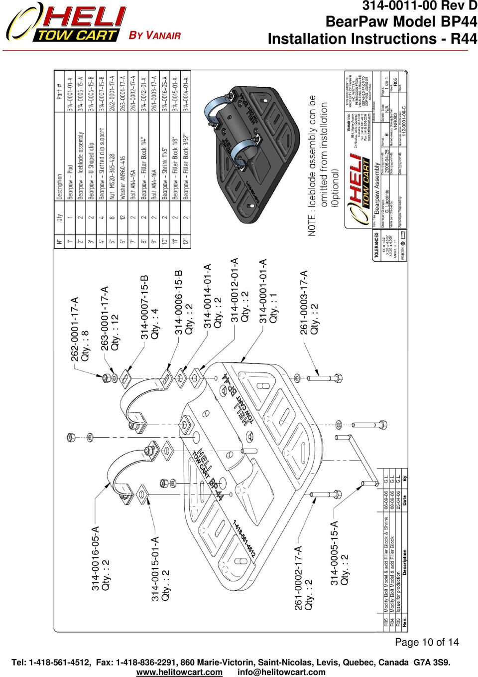
6 Parts Lists The Helitowcart BearPaw detailed parts list is as follow: Table 4 Parts List Description Qty Part No. Name (Drawing no.) BearPaw Model BP BearPaw pad C / BearPaw Assembly E / BearPaw Streamline Assembly A / BearPaw Pad (VNR088) B / BearPaw Pad Streamline Low U Shaped Clips BearPaw - Low U Shaped Clips U Shaped Clips BearPaw - U Shaped Clips (VNR087) Slotted Clip Support BearPaw - Slotted Clip Support (VNR089) Filler blocks rear BearPaw Filler block Rear Filler blocks 1/ BearPaw Filler block ¼ (VNR099) Filler blocks 3/ BearPaw Filler block 3/32 (VNR103) Filler blocks 1/ BearPaw Filler block 1/8 (VNR104) Bolts 2 Bolt- AN *(+2) *Note: for Streamline Assembly Bolts Bolt- AN4-16 Nuts 4 Nut- MS *(+2) *Note: +2 for Streamline Assembly Washers 8 Washer AN *(+8) *Note: +8 for Streamline Assembly Shrink BearPaw Shrink Specifications & Installation IceBlade Option Model OIB VNR086 / IceBlade Assembly Nuts Nut- MS Washers Washer AN Page 6 of 14
 Filler blocks rear 1 314-0022-01 BearPaw Filler block Rear Filler blocks 1/4 2 314-0012-01 BearPaw Filler block ¼ (VNR099) Filler blocks 3/32 2 314-0014-01 BearPaw Filler block 3/32")
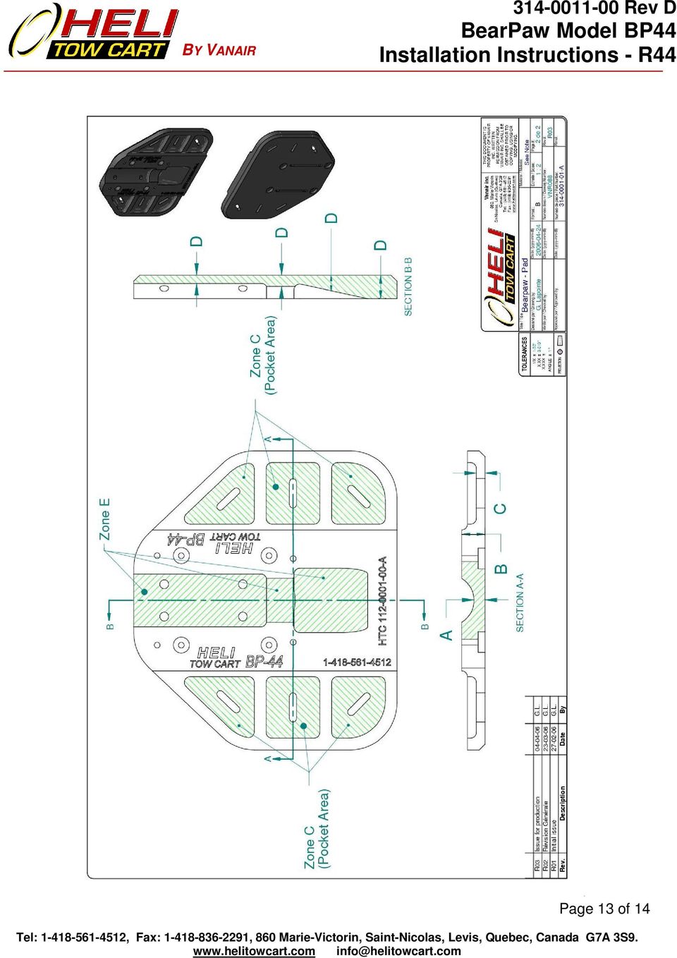
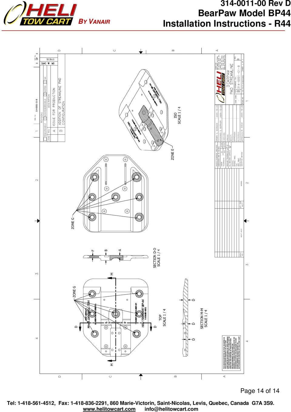
7 INSPECTION Life Limited Items There are no life limited items for the Helitowcart BearPaw. Pre-Flight Before each flight the following items should be inspected: Check that attachment bolts are installed and secured, Check that BearPaws are free from visible damage, If damage is found, verify allowable damage according to: Table 5 Tolerances for cracks & wear; Annex B BearPaw Allowable Damage Drawing ( A (VNR088) page 2 of 2) or Annex B BearPaw Streamline Allowable Damage Drawing ( B page 3 of 3). Periodic Inspection Schedule The Helitowcart BearPaw shall be inspected every 300 flying hours or yearly whichever comes first. The Helitowcart BearPaw can be inspected concurrently with the R44 landing gear inspection. Recommended tolerance for performance of inspection is +/- 10% of the 300 hours period. Following an inspection, subsequent interval shall be adjusted to meet the original schedule from time of inspection. If inspection is performed earlier than the 10% tolerance, then following inspections shall be scheduled not to exceed the above mentioned tolerance. 300 Hour or Yearly Inspection Details Remove Helitowcart BearPaw: See Section BearPaw Removal, Inspect all parts for damage & wear. See table & figure below for allowable damage, Replace all damaged parts, Replace parts worn beyond the tolerances indicated below. See Tolerances for cracks & wear: Table 5 Tolerances for cracks & wear; Annex B BearPaw Allowable Damage Drawing ( A (VNR088) page 2 of 2); or Annex B BearPaw Streamline Allowable Damage Drawing ( B page 3 of 3). Zone Nominal Dimension (Inches) Table 5 Tolerances for Cracks & Wear Allowable Damage/Wear (Inches) Cracks A 0,350 0,050 B 1,000 0,250 C 0,375 0,075 D 0,350 0,050 Stiffeners: NO cracks in stiffeners. Pockets: Cracks are acceptable in the Helitowcart BearPaw pocket areas to a maximum length of 0,5 provided they are 0,25 away from the stiffener radius change. Stop drill cracks with a 0,125 hole. Page 7 of 14
. Periodic Inspection Schedule The Helitowcart BearPaw shall be inspected every 300 flying hours or yearly whichever comes first.")
8 E N/A N/A No cracks allowed in zone E F 0,350 0,050 For P/N B Only G 0,75 0,050 For P/N B Only Overhaul Requirements Not applicable for the designated application of this device. REVISIONS & APPROVAL Revisions Date Rev Nature of Revisions April 15, 2010 D Addition of a rear U shaped clip in the Streamline BearPaw Pad configuration. October 22, 2009 C Introduction of new streamline BearPaw Pad configuration as alternate. September 7, 2006 June 12, 2006 A Initial issue B - Added filler blocks and heat shrink to product list. - Modified recommended bolt models (lengthened) - Revised inspection requirements from 100 hour to 300 hour intervals. - Identification of the IceBlade assembly as an optional feature. Approval Internal Approval : Helitowcart inc. April 15, 2010 External Approval : Lucien Barbeau, President Transport Canada April 15, 2010 Mirko Zgela, DAR #310 Annex A See: BearPaw Assembly, drawing no C BearPaw Streamline Assembly, drawing no E Annex B See: BearPaw Pad Allowable Damage Drawing, drawing no A (VNR088) page 2 of 2. BearPaw Streamline Allowable Damage Drawing, drawing no B page 3 of 3) Page 8 of 14
 - Revised inspection requirements from 100 hour to 300 hour intervals. - Identification of the IceBlade assembly as an optional feature.")
9 Annex A BearPaw Assembly, Drawing no C BearPaw Streamline Assembly, Drawing no E Page 9 of 14

10 Page 10 of 14
11 BY VANAIR Page 11 of 14

12 Annex B BearPaw Pad Allowable Damage Drawing, Drawing no A (VNR088), Page 2 of 2 BearPaw Streamline Allowable Damage Drawing, Drawing no B, Page 3 of 3 Page 12 of 14

13 Page 13 of 14
14 Page 14 of 14
TECHNICAL BULLETIN SUBJECT: AFT FUSELAGE BULKHEAD 407-030-027-101 AT FS 231.4, INTRODUCTION OF.
 TECHNICAL BULLETIN DATE REV No. 407-07-78 Date SEP 19, 2007 Page 1 of 17 MODEL AFFECTED: 407 SUBJECT: AFT FUSELAGE BULKHEAD 407-030-027-101 AT FS 231.4, INTRODUCTION OF. HELICOPTERS AFFECTED: Model 407
758 Heavy-duty Ratchet Guy Wire Cutter
 INSTRUCTION MANUAL 758 Heavy-duty Ratchet Guy Wire Cutter Read and understand all of the instructions and safety information in this manual before operating or servicing this tool. Register this product
KEEP FOR FUTURE REFERENCE MRTALP VERTICAL LIFT BAR READ ALL INSTRUCTIONS AND WARNINGS BEFORE USING THIS PRODUCT
 KEEP FOR FUTURE REFERENCE INSTRUCTIONS P.O. Box 368 908 West Main Laurel, MT USA 59044 phone 800-548-7341 phone 406-628-8231 fax 406-628-8354 International Version MODEL NUMBER: LB10VLB MRTALP VERTICAL
R O A D M A S T E R, I N C.
 R O A D M A S T E R, I N C. ROADMASTER, Inc. 6110 NE 127th Ave. Vancouver, WA 98682 6 13 11 MOUNTING BRACKET KIT Cable Tab 14 12 7 15 9 Cable Tab 360-896-0407 fax 360-735-9300 www.roadmasterinc.com ITEM
Installation Instructions GOOSENECK MOUNTING KIT Chevrolet/GMC 1500/2500/3500 All except 4-door Crew-Cab
 GOOSENECK MOUNTING KIT Equipment Required: Fastener Kit: F Wrenches: 3/4, 7/8, 15/16 Drill Bits: 1/4 Other Tools: Drill WARNING: Under no circumstances do we recommend exceeding the towing vehicle manufacturers
»Product» Safety Warning
 C1200 Installation Instructions 2007-2016 Chevy/GM 1500 2/4wd 2" Strut Spacer Lift Read and understand all instructions and warnings prior to installation of product and operation of vehicle. Zone Offroad
Rack Installation Instructions
 Rack Installation Instructions Second Edition (June 2014) 2014 Contents Chapter 1. Safety information..... 1 Chapter 2. Rack kit parts inentory... 3 Chapter 3. Rack installation...... 5 Identifying the
SAFETY & OPERATING INSTRUCTIONS
 SAFETY & OPERATING INSTRUCTIONS EDLUND TOMATO LASER, Models ETL -316, -140 & -380 READ AND UNDERSTAND THIS MANUAL AND ALL INSTRUCTIONS BEFORE OPERATING THIS SLICER. 159 Industrial Parkway, Burlington,
MEDIUM FLAT PANEL DISPLAY STATIC MOUNT MSR Series
 INSTALLATION INSTRUCTIONS MEDIUM FLAT PANEL DISPLAY STATIC MOUNT The static mount accommodates medium flat panel displays weighing up to 125 lbs (57 kgs). The teardrop holes in the mount allow for quick
Rebuild Instructions for 70001 and 70010 Transmission
 Rebuild Instructions for 70001 and 70010 Transmission Brinn, Incorporated 1615 Tech Drive Bay City, MI 48706 Telephone 989.686.8920 Fax 989.686.6520 www.brinninc.com Notice Read all instructions before
Model No. BC460-H Alternator. B & C Specialty Products P.O. Box B Newton, KS 67114 (316) 283-8000
 283-8000") Installation Instructions for Model No. BC460-H Alternator for Lycoming Engines B & C Specialty Products P.O. Box B Newton, KS 67114 (316) 283-8000 BC460-H_Install, Rev. C (12/16/15) NOTE The BC460-H Alternator
Installation Instructions for Model No. BC460-H Alternator for Lycoming Engines B & C Specialty Products P.O. Box B Newton, KS 67114 (316) 283-8000 BC460-H_Install, Rev. C (12/16/15) NOTE The BC460-H Alternator
READ AND UNDERSTAND ALL INSTRUCTIONS AND WARNINGS PRIOR TO INSTALLATION OF SYSTEM AND OPERATION OF VEHICLE.
 491 W. Garfield Ave., Coldwater, MI 49036 Phone: 517-279-2135 Web/live chat: www.bds-suspension.com E-mail: tech-bds@sporttruckusainc.com Product: GM Leaf Spring READ AND UNDERSTAND ALL INSTRUCTIONS AND
Chapter 5 FLOOR LOADING AND WEIGHTS
 Chapter 5 FLOOR LOADING AND WEIGHTS Section 1.0 Floor Loading Section 2.0 Seismic Data The CT system has a total floor load of approximately 6660 lbs (3021 kg). About 5050 lbs (2291 kg), including patient
R O A D M A S T E R, I N C.
 R O A D M A S T E R, I N C. MOUNTING BRACKET KIT 12 3 6 9 5 11 ITEM QTY NAME MATERIAL 1...4...1/2" x 1 1/2" BOLT... 350095-00 2...4...1/2" x 1 1/2" CARRIAGE BOLT... 350362-00 3...8...1/2" NUT... 350258-00
Installation Guide for the TJ LCG PRO Suspension System (Low Center of Gravity) Available 4 or 5
 Available 4 or 5") INSTALLATION GUIDE Installation Guide for the TJ LCG PRO Suspension System (Low Center of Gravity) Available 4 or 5 Take every precaution to make this installation a safe procedure. Make safety the number
INSTALLATION GUIDE Installation Guide for the TJ LCG PRO Suspension System (Low Center of Gravity) Available 4 or 5 Take every precaution to make this installation a safe procedure. Make safety the number
LG G5 Chassis Brace Gen 5 Camaro THE MOST POWERFUL HEADERS ON THE PLANET Brought to you by LG Motorsports 972-429-1963
 LG G5 Chassis Brace Gen 5 Camaro THE MOST POWERFUL HEADERS ON THE PLANET Brought to you by LG Motorsports 972-429-1963 Thank you for purchasing LG Motorsports products for your Gen 5 Camaro. Parts Inventory:
STEADYfast Stabilizer Installation Notes Fifth Wheel and Travel Trailers 11/23/13
 STEADYfast Stabilizer Installation Notes Fifth Wheel and Travel Trailers 11/23/13 (See Supplemental Instructions for trailers with heavy duty round footplates and/or Power Leveling Systems) PHONE SUPPORT
R O A D M A S T E R, I N C.
 R O A D M A S T E R, I N C. 11 10 20 12 4 18 19 1 2 13 16 ITEM QTY NAME MATERIAL 1...2... 1/2" x 3 1/2" BOLT... 350103-00 2...2... 1/2" x 2" BOLT... 350097-00 3...6... 1/2" x 1 1/2" BOLT... 350095-00 4...2...
INSTALLATION INSTRUCTIONS. 6111 Air Spring Kit 2011+ Ford F250/F-350 Single Wheel 2WD 2011+ Ford F350 Dually 2WD IMPORTANT NOTES
 INSTALLATION INSTRUCTIONS 6111 Air Spring Kit 2011+ Ford F250/F-350 Single Wheel 2WD 2011+ Ford F350 Dually 2WD Thank you for purchasing a quality Hellwig Product. PLEASE READ THIS INSTRUCTION SHEET COMPLETELY
XM-4434. Owner s Manual POWER TOWER !CAUTION. Read all precautions and instructions in this manual before using this equipment.
 XM-4434 POWER TOWER Owner s Manual!CAUTION Read all precautions and instructions in this manual before using this equipment. Table of Contents Important Safety Information 3 Assembly 4-7 Parts List 8 Exploded
MODEL G300 BRAKE BLEEDER
 MODEL G300 BRAKE BLEEDER Installation, Operation & Repair Parts Information Branick Industries, Inc. 4245 Main Avenue P.O. Box 1937 Fargo, North Dakota 58103 REV060616 P/N: 81-0035G 1 THIS PAGE INTENTIONALLY
R O A D M A S T E R, I N C.
 R O A D M A S T E R, I N C. 11 7 6 1 2 10 13 8 ITEM QTY NAME PART # 1...2...1/2 x 5 1/2 BOLT...350108-00 2...4...1/2 x 1 3/4 BOLT...350096-00 3...6...1/2 LOCK WASHER...350309-00 4...6...1/2 HEX NUT...350258-00
ReadyLift (Part# 66-5075) Strut Extension, Installation Instructions Toyota Tundra New Body Style 2WD & 4WD
 Strut Extension, Installation Instructions Toyota Tundra New Body Style 2WD & 4WD") SAFETY WARNING: recommends this system be installed by a professional technician. In addition to these instructions, professional knowledge of disassembly/ reassembly procedures and post installation checks
SAFETY WARNING: recommends this system be installed by a professional technician. In addition to these instructions, professional knowledge of disassembly/ reassembly procedures and post installation checks
SERVICE. 28R-7135001 thru 28R-7135229 PA-28R-200 Arrow II 28R-7235001 thru 28R-7635545
 Piper Aircraft, Inc. 2926 Piper Drive Vero Beach, Florida, U.S.A. 32960 SERVICE NO. 1242 BULLETIN PIPER CONSIDERS COMPLIANCE MANDATORY Date: January 30, 2015 (S) (M) Service Bulletin (SB) 1242 supersedes
16 April 2012 1032011-F 1994-2002 Dodge Adjustable Track bar with Relocation Bracket 1
 16 April 2012 1032011-F 1994-2002 Dodge Adjustable Track bar with Relocation Bracket 1 BD Adjustable Track Bar w/bracket Dodge 2500-3500 4WD Models 1994-2002 Dodge 1500 4WD Model 1994-2001 P/N# 1032011-F
R O A D M A S T E R, I N C.
 R O A D M A S T E R, I N C. ROADMASTER, Inc. 6110 NE 127th Ave. Vancouver, WA 98682 12 10 3 11 4 5 13 7 8 360-896-0407 fax 360-735-9300 www.roadmasterinc.com ITEM QTY NAME MATERIAL 1... 4...1/2 x 1 1/2
Check for deteriorated, shifting or missing tie-down pads. Replace if needed.
 C C 0 5 C H A S S I S F R A M E Chassis Frame Overview The Blue Bird Vision s chassis frame consists of two main C-channel rails which run the entire length of the bus, and several different kinds of cross
MEASURING WHEEL ALIGNMENT
 MEASURING WHEEL ALIGNMENT 2003-04 WHEEL ALIGNMENT Specifications & Procedures - Hummer - H2 Steering and vibration complaints are not always the result of improper alignment. One possible cause is wheel
HOME GYM. Model. Retain This Manual for Reference OWNER'S MANUAL. www.hyper-extension.com
 NOTE: Please read all instructions carefully before using this product Table of Contents Safety Notice www.hyper-extension.com HOME GYM 50036 Hardware Identifier Assembly Instruction Parts List Warranty
1999-2010 GENERAL MOTORS 3/4 &1 TON RT3 UNDERCARRIAGE MOUNTING INSTRUCTIONS (PART NO. LTA04767B)
") 1999-010 GENERAL MOTORS 3/4 &1 TON MOUNTING INSTRUCTIONS (PART NO. LTA04767B) MSC04380-8 WARNING Many newer trucks are now equipped with air bags. DO NOT under any circumstances disable, remove or relocate
1999-010 GENERAL MOTORS 3/4 &1 TON MOUNTING INSTRUCTIONS (PART NO. LTA04767B) MSC04380-8 WARNING Many newer trucks are now equipped with air bags. DO NOT under any circumstances disable, remove or relocate
INSTALLATION AND OPERATING INSTRUCTIONS For Model GL1 Gate Locks
 Securitron Magnalock Corp. www.securitron.com ASSA ABLOY, the global leader Tel 800.624.5625 techsupport@securitron.com in door opening solutions INSTALLATION AND OPERATING INSTRUCTIONS For Model GL1 Gate
R O A D M A S T E R, I N C.
 R O A D M A S T E R, I N C. 6 28 1 2 "ā 1 2 " 4 8 ITEM QTY NAME PART # 1...4...1/2 x 1 1/4 BOLTS... 350094-00 2...4...1/2 LOCK WASHER... 350309-00 3...4...1/2 HEX NUT... 350258-00 4...2...SPACER PLATE...
Lathe Milling Attachment
 Lathe Milling Attachment By L C. MASON BY CLEVERLY stacking cold-rolled flat stock together, T-slots and slide for this lathe milling attachment are made without costly machinery. In fact, only two tools,
Toroidal Conductivity Sensor
 Instruction Sheet PN 51A-/rev.C June 2012 Toroidal Conductivity Sensor For additional information, please visit our website at www.emersonprocess.com/rosemountanalytical.com SPECIFICATIONS Wetted Materials:
R O A D M A S T E R, I N C.
 R O A D M A S T E R, I N C. MOUNTING BRACKET KIT 14 8 7 4 13 5 6 ITEM QTY NAME MATERIAL 1...6...1/2" x 2 1/2" BOLT... 350099-00 2...2...1/2" x 1 1/2" BOLT... 350095-00 3...8...1/2" LOCK WASHER... 350309-00
Chapter 61. Propeller
 Chapter 61 Propeller PAGE 1 Table of Contents Chapter Title 61-00-00 GENERAL.................................. 3 61-10-00 PROPELLER............................... 4 61-20-00 CONTROLLING.............................
Finding and Fixing Oil leaks on the LT5 Engine Marc Haibeck
 Finding and Fixing Oil leaks on the LT5 Engine Marc Haibeck Most LT5 s drip oil on the floor by the time 10,000 miles are covered. This may be disappointing, but it is not as bad as it may seem. Here s
Installation Instructions
 Installation Instructions Page 1 of 16 January 2008 Equipment Parts, Trailer Hitch Ver 3.0 Accessory Development SUBJECT TRAILER HITCH KIT (US Only) - P/N 71 60 0 413 359 MODEL X5 (E70): Select Vehicle
MANDATORY SERVICE BULLETIN
 652 Oliver Street Williamsport, PA 17701 U.S.A. Tel. +1-800-258-3279 (U.S. and Canada) Tel. +1-570-323-6181 (International) Fax. +1-570-327-7101 www.lycoming.com MANDATORY SERVICE BULLETIN DATE: October
ALERT SERVICE BULLETIN Checking of the cylinder head assy. 2/3 for ROTAX Engine Type 912 and 914 (Series)
") ASB-912-062UL R1 ASB-914-044UL R1 Checking of the cylinder head assy. 2/3 for ROTAX Engine Type 912 and 914 (Series) This ASB revises ASB-912-062UL/ASB-914-044UL Initial issue ATA System: 72-30-00 Cylinder
ASB-912-062UL R1 ASB-914-044UL R1 Checking of the cylinder head assy. 2/3 for ROTAX Engine Type 912 and 914 (Series) This ASB revises ASB-912-062UL/ASB-914-044UL Initial issue ATA System: 72-30-00 Cylinder
Guidelines for Earthquake Bracing Residential Water Heaters
 Guidelines for Earthquake Bracing Residential Water Heaters Department of General Services Division of the State Architect In accordance with the Health and Safety Code Section 19215, the Division of the
I BEAM TRACK INSTALLATION
 PDQ 0/700 FESTOON SYSTEM INSTALLATION AND MAINTENANCE INSTRUCTIONS INTRODUCTION The PDQ Festoon System was designed to run on one of three sizes of I-beams: S x., S8 x 8. and S x.. System trolleys must
LIFT-505. BMF Lift Kit. Yamaha Drive Gas or Electric. Installation Instructions
 LIFT-505 BMF Lift Kit Yamaha Drive Gas or Electric Installation Instructions Contents of LIFT-505 Yamaha Drive BMF Lift Kit: a (1 ea.) BMF A-Arm Assembly b (1 ea.) Driver Side Shock Tower c (1 ea.) Passenger
CorkSport Mazdaspeed 6 Rear Sway Bar 2006-2007 Mazdaspeed 6
 CorkSport Mazdaspeed 6 Rear Sway Bar 2006-2007 Mazdaspeed 6 Pre-Installation Notes: The CorkSport Rear Sway Bar is a great addition to improving the handling performance to the Mazdaspeed 6. It will minimize
READ CAREFULLY - FAILURE TO FOLLOW INSTRUCTIONS AND SAFETY RULES MAY RESULT IN SERIOUS INJURY
 Owner s Manual LSP16H LS3001 LS3002H LS3003 LSP21H LS3101 LS3102H LS3103 LSP24H LS3201 LS3102H LS3103 LSP28H LS3301 LS3302H LS3303 mainframe bundle H-unit bundle accessory box mainframe bundle H-unit bundle
LYCOMING O-360. Engine Installation
 Engine Installation SECTION 4 Carburetor Heat Box Carb. Heat Box, hole at the bottom is the hot air exit when carb heat is not used. SECTION 4 - Page 1 of 13 Push Pull cable P/N 05-14084 Qty = 1 Length=7ft.
CHAPTER 65 TAIL ROTOR DRIVE SYSTEM. Section Title Page
 CHAPTER 65 TAIL ROTOR DRIVE SYSTEM Section Title Page 65-00 Description........................................ 65.1 65-10 Tail Rotor Drive Fan Shaft.............................. 65.1 65-20 Tail Rotor
1.8 CRANKSHAFT OIL SEALS
 SERIES 60 SERVICE MANUAL 1.8 CRANKSHAFT OIL SEALS An oil seal is fitted between each end of the crankshaft and the bores of the flywheel housing and gear case cover to retain the lubricating oil in the
Thank You For Choosing. INSTALLATION INSTRUCTIONS Portal Gear Hubs Polaris RZR XP 900 Crew. (Right) (Left)
 (Left)") 740B Clifty Drive Madison, Indiana 47250 812-574-7777 INSTALLATION INSTRUCTIONS Portal Gear Hubs Polaris RZR XP 900 Crew A Item Description Qty A Rotor 4 B Gear Box, L 2 C Gear Box, R 2 D Gasket 4 E Cap
740B Clifty Drive Madison, Indiana 47250 812-574-7777 INSTALLATION INSTRUCTIONS Portal Gear Hubs Polaris RZR XP 900 Crew A Item Description Qty A Rotor 4 B Gear Box, L 2 C Gear Box, R 2 D Gasket 4 E Cap
MGB Chrome Bumper Conversion
 MGB Chrome Bumper Conversion Installation Instructions For 1974 1/2-1980 MGB This kit requires cutting, welding, and painting. Professional installation recommended. Note: Every MGB body is slightly different
FL ADJUSTABLE RIDER BACKREST MOUNTING HARDWARE KIT
 -J070 REV. 0-0-0 FL ADJUSTABLE RIDER BACKREST MOUNTING HARDWARE KIT GENERAL Kit Number 9-09A Models For model fitment information, see the P&A Retail Catalog or the Parts and Accessories section of www.harley-davidson.com
Little British Car Co.
 Little British Car Co. 29311 Aranel, Farmington Hills, MI 48334-2815, USA Tel: 248 489 0022 or 800 637 9640 Fax: 248 489 9665 On the web at: www.lbcarco.com E-mail: LBCarco@LBCarCo.com MGB Tube Rear Shock
STEEL-RITE II or III COMMERCIAL SECTIONAL DOOR Owner s Manual Supplement Model 52242 NOTICE TO USER
 STEEL-RITE II or III COMMERCIAL SECTIONAL DOOR Owner s Manual Supplement Model 52242 NOTICE TO USER Thank you for purchasing the Steel-Rite II or III, model 52242 commercial sectional door from RITE-HITE
R O A D M A S T E R, I N C.
 R O A D M A S T E R, I N C. ROADMASTER, Inc. 6110 NE 127th Ave. Vancouver, WA 98682 4 MOUNTING BRACKET KIT 1 2 3 360-896-0407 fax 360-735-9300 www.roadmasterinc.com ITEM QTY NAME PART # 1...2... #10 x
FJ2. 2 Ton Trolley Floor Jack Assembly & Operating Instructions
 FJ2 2 Ton Trolley Floor Jack Assembly & Operating Instructions READ ALL INSTRUCTIONS AND WARNINGS BEFORE USING THIS PRODUCT. This manual provides important information on proper operation & maintenance.
MUSTANG II IFS COMPLETE PARTS PACKAGE
 MUSTANG II IFS COMPLETE PARTS PACKAGE Your Southern Rods & Parts Mustang II IFS Parts Package contains the following items: 1 pr) Upper Control Arms (2023) 1) Upper Arm Bolt Kit (MP-001-A) 1 pr) Lower
PowerFlex 700S and 700H Frame 12 DC Bus Connector Kit
 PowerFlex 700S and 700H Frame 12 DC Bus Connector Kit Installation Instructions This document provides instructions for the installation of a DC bus connector kit for PowerFlex 700S and 700H frame 12 drives
Service Bulletin No. SB 06-2-23 MANDATORY SERVICE BULLETIN. Safetying of standard and flop-type fuel pickup tubes.
 VAN S AIRCRAFT, INC. 14401 NE Keil Road, Aurora, Oregon, USA 97002 PHONE 503-678-6545 FAX 503-678-6560 www.vansaircraft.com info@vansaircraft.com Service Bulletin No. SB 06-2-23 MANDATORY SERVICE BULLETIN
4 in 1 Strength Station
 Revision 0 September 2010 4 in 1 Strength Station Owner s Manual Record Serial Number Here Platinum by Tunturi www.tunturi.com Date www.tunturi.com of Purchase 4 in 1 Strength Station Owner s Manual Instructions
The Crankshaft Oil Seal Section has been added to the DD15 Workshop Manual. The sections that are found in the Engine Chapter are now renumbered.
 NUMBER: 08 DD15-5 S.M. REF.: 1.11 ENGINE: DD15 DATE: July 2008 SUBJECT: CRANKSHAFT OIL SEAL SECTION PUBLICATION: DDC-SVC-MAN-0002 The Crankshaft Oil Seal Section has been added to the DD15 Workshop Manual.
Technical Service Bulletin
 Subject FOUR WHEEL ALIGNMENT - EZ CAM TM XR CAMBER ANGLE ADJUSTING BOLTS Date Model [X] PARTS MANAGER JANUARY, 2008 2003-2008 TIBURON [X] TECHNICIAN CIRCULATE TO: [ ] GENERAL MANAGER [X] SERVICE ADVISOR
INSTALLATION INSTRUCTIONS. 6108 Air Spring Kit 2011+ Ford F250 Single Wheel 4WD 2011+ Ford F350 Dually 4WD (2011 F350 Single Wheel 4WD use p/n 6113)
") INSTALLATION INSTRUCTIONS 6108 Air Spring Kit 2011+ Ford F250 Single Wheel 4WD 2011+ Ford F350 Dually 4WD (2011 F350 Single Wheel 4WD use p/n 6113) Thank you for purchasing a quality Hellwig Product. PLEASE
INSTALLATION INSTRUCTIONS 6108 Air Spring Kit 2011+ Ford F250 Single Wheel 4WD 2011+ Ford F350 Dually 4WD (2011 F350 Single Wheel 4WD use p/n 6113) Thank you for purchasing a quality Hellwig Product. PLEASE
INSTRUCTIONS THOROUGHLY BEFORE BEGINNING***************
 Bill of Materials: RAC0012 Green Wing Aerodynamic Skirt Kit Item Part Number Description Quantity 1 RMC0218 Gen 2 Trailer Skirt Roadside 1 2 RMC0219 Gen 2 Trailer Skirt Curbside 1 3 RMC0041 Trailer Skirt
SIMRAD SD10 Sailboat Drive
 INSTALLATION MANUAL SIMRAD SD10 Sailboat Drive 20222683/A English Simrad SD10 Sailboat Drive About this document Rev. A First issue 2007 Navico AS. All rights reserved. No part of this work covered by
SELF-STEERING AXLE TABLE OF CONTENTS
 SELF-STEERING AXLE TABLE OF CONTENTS Section 1 - Introduction Section 2 - Pre-Installation Check List Section 3 - Ride Height Adjustments Section 4 - Suspension Mount Section 5 - Axle Mount Section 6 -
Trillium 40 Axis Spring Tensioner Wire Replacement Instructions
 Trillium 40 Axis Spring Tensioner Wire Replacement Instructions 1 Overview The objective is to replace the broken axis spring tensioner wire. This requires the following tasks: 1. Remove the seismometer
PEDAL CAR - GO CART ASSEMBLY & OPERATING INSTRUCTIONS
 PEDAL CAR - GO CART 42822 ASSEMBLY & OPERATING INSTRUCTIONS 3491 Mission Oaks Blvd., Camarillo, CA 93011 Visit our Web site at: http://www.harborfreight.com Copyright 2000 by Harbor Freight Tools. All
INSTRUCTIONS. FLHR/C/S (Road King) FRONT END LOWERING KIT 1WARNING -J03242 REV. 10-19-04. General. Removal (Left and Right Forks) Kit Number 54614-05
 FRONT END LOWERING KIT 1WARNING -J03242 REV. 10-19-04. General. Removal (Left and Right Forks) Kit Number 54614-05") INSTRUCTIONS -J04 REV. 0-9-04 General FLHR/C/S (Road King) FRONT END LOWERING KIT This kit is designed for installation on 00 and later FLHR/C/S Model Motorcycles. Road King models use the conventional
INSTRUCTIONS -J04 REV. 0-9-04 General FLHR/C/S (Road King) FRONT END LOWERING KIT This kit is designed for installation on 00 and later FLHR/C/S Model Motorcycles. Road King models use the conventional
M128 SERVICE MANUAL- M128 MODEL #S-11 MANUAL CAN OPENER
 SERVICE MANUAL- M128 MODEL #S-11 MANUAL CAN OPENER 1 Model S-11 Can Opener Assembly Procedure The Model S-11 can opener will be assembled according to the following procedure: I. Model S-11 Handle and
HermanMiller Aeron Posturefit Installation AE905A AE905B AE905C
 HermanMiller Aeron Posturefit Installation AE905A AE905B AE905C Y How to assemble to your chair Parts Included Posturefit Mechanism For more information about our products and services or to see a list
SUPERCHIPPER CASTING MAINTENANCE
 INTRODUCTION By design, the Superchipper Rotor is clad in castings which wear during crushing. The castings wear at different rates depending on their location on the rotor, material feed rate, material
Thank You For Choosing. INSTALLATION INSTRUCTIONS Portal Gear Hubs Polaris RZR 800. (installation performed on 60 Model) (Right) (Left)
 (Right) (Left)") 740B Clifty Drive Madison, Indiana 47250 812-574-7777 INSTALLATION INSTRUCTIONS Portal Gear Hubs Polaris RZR 800 A (installation performed on 60 Model) Item Description Qty A Rotor 4 B Gear Box, L 2 C
740B Clifty Drive Madison, Indiana 47250 812-574-7777 INSTALLATION INSTRUCTIONS Portal Gear Hubs Polaris RZR 800 A (installation performed on 60 Model) Item Description Qty A Rotor 4 B Gear Box, L 2 C
ENGLISH FORK GUIDE 2013
 FORK GUIDE 2013 ENGLISH 1 With a brand which is synonymous with specialists in forest products handling attachments, BOLZONI AURAMO offers its expertise and market leading attachments for all requirements,
880 HYDRAULIC BENDER
 OPERATION, SERVICE AND PARTS INSTRUCTION MANUAL 880 HYDRAULIC BENDER Read and understand this material before operating or servicing this tool. Failure to understand how to safely operate this tool could
COMPLETE KIT PARTS LIST
 Your kit contains the following parts. Please check your kit for any missing or damaged parts before starting construction. Wood Bag: COMPLETE KIT PARTS LIST 1 LC-504-01 3/32"x4"x24" Laser Cut Balsa Sheet
Acceptability of Printed Circuit Board Assemblies
 Section No.: 12I.2.3, Sheet 1 of 9 Rev Level: 16 Additional Distribution: PCB Assembly Subcontractors 1.0 Purpose 2.0 Scope Acceptability of Printed Circuit Board Assemblies 1.1 The purpose of this standard
Checking Wheel Brakes Wear
 Issue 1 en 1 Checking Wheel Brakes Wear Contents Disc Brakes... 3 Removing the wheels... 4 Checking the Brake Pads... 5 Check brake disc thickness... 7 Checking brake disc for cracks... 8 Drum Brakes...
PowerFlex 700H and 700S AC Drives Frame 11 Main Fan Capacitor Replacement Kit
 Installation Instructions PowerFlex 700H and 700S AC Drives Frame 11 Main Fan Capacitor Replacement Kit ATTENTION: The sheet metal cover and mounting screws on the ASIC Board located on the power structure
POLE MOUNT SYSTEM EX-3 INSTALLATION
 May 2014 POLE MOUNT SYSTEM EX-3 INSTALLATION The Pole Mount System EX-3 is an easy to install and flexible system designed to allow ONE SYSTEMS loudspeaker systems to be mounted to pole structures. The
ALERT SERVICE BULLETIN 412-12-152 18 December 2012 ENGINE FIRE EXTINGUISHER BOTTLE STEM INSPECTION
 ALERT SERVICE BULLETIN 412-12-152 18 December 2012 MODEL AFFECTED: SUBJECT: 412/412EP ENGINE FIRE EXTINGUISHER BOTTLE STEM INSPECTION HELICOPTERS AFFECTED: Serial numbers 33001 through 33213, 34001 through
Hydraulic Transmission Jacks Operating Instructions & Parts Manual
 Blackhawk Automotive is a Licensed Trade Mark Made by SFA Companies, Kansas City, MO Hydraulic Transmission Jacks Operating Instructions & Parts Manual Model BH7011 BH7210 Capacity 1/2 Ton 1 Ton SFA Companies
Product Notice. Safety Notice: Sales Hold
 Product Notice Ariens Company 655 W. Ryan St. Brillion, WI 54110 www.ariens.com Product Family: Ariens and Gravely 36 Power Brushes Subject: Sales Hold Inspect and Repair Dealer Action: SALES HOLD Do not
WARNING! WARNING! ALWAYS WEAR A TMA APPROVED FALL ARREST SYSTEM WHEN USING ANY TREESTAND
 WARNING! You must read and understand all of the following instructions before first use. If you do not, it could result in serious injury up to and including death. Any questions please call 309-691-9653.
P7100 PUMP INSTALLATION INSTRUCTIONS Diesel Care & Performance Inc
 P7100 PUMP INSTALLATION INSTRUCTIONS Diesel Care & Performance Inc Installation Timing Pin Location CAUTION: Before installing the injection pump, be sure that number 1 cylinder is at the Top Dead Center
LU6X-130 Instructions and Parts List (including LU6X Basic) Operating Instructions
 Operating Instructions") LORTONE LU6X-130 Item # 061-092 LU6X Basic Item # 061-090 LU6X-130 Instructions and Parts List (including LU6X Basic) Operating Instructions Introduction The LU6X is one the most versatile pieces of equipment
LORTONE LU6X-130 Item # 061-092 LU6X Basic Item # 061-090 LU6X-130 Instructions and Parts List (including LU6X Basic) Operating Instructions Introduction The LU6X is one the most versatile pieces of equipment
Flat Bottom Long Ram Hydraulic Jack
 Flat Bottom Long Ram Hydraulic Jack 3 Ton 8 Ton 36468 36469 ASSEMBLY & OPERATING INSTRUCTIONS 349 Mission Oaks Blvd., Camarillo, CA 930 Visit our Web site at http://www.harborfreight.com TO PREVENT SERIOUS
R O A D M A S T E R, I N C.
 R O A D M A S T E R, I N C. ROADMASTER, Inc. 6110 NE 127th Ave. Vancouver, WA 98682 8 7 1 6 15 28 1 2 "± 1 2 " MOUNTING BRACKET KIT 3 2 10 14 4 5 9 360-896-0407 fax 360-735-9300 www.roadmasterinc.com Item
R O A D M A S T E R, I N C.
 R O A D M A S T E R, I N C. ROADMASTER, Inc. 6110 NE 127th Ave. Vancouver, WA 98682 16 6 18 Cable Tab 13 15 8 10 2 Cable Tab 1 11 9 17 14 360-896-0407 fax 360-735-9300 www.roadmasterinc.com ITEM QTY NAME
Valu Guide Sheaths. Valu Guide Inserts. Optional Valu Guide Inserts. Typical Properties of Valu Guide Rail. and Hardware.
 14 gauge stainless steel The Original, Long Life Sanitary Guide Rail Valu Guide rail incorporates two outstanding materials: stainless steel and UHMW. The 14 ga. stainless steel sheath provides rigid streamlined
Two most common lock nut groups: 1-Prevailing Torque Type Lock Nuts:
 Two most common lock nut groups: 1. PREVAILING TORQUE a design feature of the lock nut produces friction between threads of mated components thereby increasing the force needed to tighten as well as loosen
FIXED PLATE INSTALLATION FOR STRAIGHT TRUCKS
 FIXED PLTE INSTLLTION FOR STRIGHT TRUCKS For staight trucks only, not for trailers. For single stage and two stage mast forklifts. Dump Bodies require special construction, contact for specific instructions.
RI27-J CNG REDUCER INSTALLATION PROVISIONS & WARNINGS
 RI27-J CNG REDUCER INSTALLATION PROVISIONS & WARNINGS Rev.01.02 BIGAS INTERNATIONAL AUTOGAS SYSTEMS S.r.l. Via di Le Prata, 62/66-50041 Calenzano Firenze ITALY Tel. 0554211275 - Fax 0554215977 http: www.bigas.it
Guidelines for Earthquake Bracing of Residential Water Heaters
 Guidelines for Earthquake Bracing of Residential Water Heaters Department of General Services Division of the State Architect 1102 Q Street, Suite 5100 Sacramento, CA 95814 Phone: (916) 324-7099 Fax: (916)
Oregon Fuel Injection
 Corporate Office: P.O. Box 21121, VE Pump Removal and Installation Cummins Lock Timed Applications Removal Clean the exterior of the injection pump and mounting surfaces. 1. Disconnect the fuel return
Router Table Plans. www.bobsplans.com
 www.bobsplans.com Router Table Plans Increase the capabilities of your router with this weekend project. Features a sliding fence with EZ-Mount clamps. These clamps are simple to make and grip tightly
Set-Up Instructions. (Liner-Based System) UL LISTED. Important Read set-up instructions before assembly. Report any shortages within 72 hours
 UL LISTED. Important Read set-up instructions before assembly. Report any shortages within 72 hours") INDUSTRIAL POWER Set-Up Instructions (Liner-Based System) UL LISTED Important Read set-up instructions before assembly. Report any shortages within 72 hours Specializing in Environmental and Fire-Life
INDUSTRIAL POWER Set-Up Instructions (Liner-Based System) UL LISTED Important Read set-up instructions before assembly. Report any shortages within 72 hours Specializing in Environmental and Fire-Life
AirFilm Camera Systems
 AirFilm Camera Systems REPORT NO. INSTALLATION INSTRUCTIONS AFDP-1 DOWN POST UTILITY BRACKET DATE ISSUED: 3/25/2005 AirFilm Camera Systems 6245 Aerodrome Way Hangar No. 2 Georgetown, Ca 95634 LOG OF REVISIONS
ISORIA. Centered disc butterfly valves with AMRING elastomer liner. 240 PSI: 1½ to8. 150 PSI : 10 to 24
 Type series booklet 8448.1/2-EN--US ISORIA Centered disc butterfly valves with AMRING elastomer liner 240 PSI: 1½ to8 150 PSI : 10 to 24 Design in accordance with ISO 10631 Manual, electrical, pneumatical
EMERGENCY EGRESS LIGHTING POWER SUPPLY PART NO. 5925-6 COMPONENT MAINTENANCE MANUAL WITH ILLUSTRATED PARTS LIST
 EMERGENCY EGRESS LIGHTING POWER SUPPLY PART NO. WITH ILLUSTRATED PARTS LIST Initial Issue: June 16, 1995 33-51-80Page 1 May 20/2010 RECORD OF REVISIONS REV. NO. ISSUE DATE A 01-26-96 B 09-21-99 C 10-26-09
Structural Bolting. Notice the Grade 5 has a much smaller head configuration and a shorter shank then the A325 structural bolt. Rev.
 Structural Bolting ASTM A325 and ASTM A490 are the two U.S. standard structural bolts. When looking at the mechanical requirements of bolts it appears that an ASTM A325 and SAE J429 Grade 5 are identical