NI USB-634x/635x/636x OEM
|
|
|
- Owen Clark
- 7 years ago
- Views:
Transcription
1 USER GUIDE NI USB-x/x/x OEM X Series USB-///// OEM Devices This document provides dimensions, pinouts, and information about the connectors, switch, LEDs, and mounting holes of the National Instruments USB- OEM, USB- OEM, USB- OEM ( MS), USB- OEM, USB- OEM, and USB- OEM ( MS) devices. It also explains how to modify the USB device name in Microsoft Windows. Caution The protection provided by the NI USB-x/x/x OEM device can be impaired if it is used in a manner not described in this document or the X Series User Manual. Caution There are no product safety, electromagnetic compatibility (EMC), or CE marking compliance claims made for the NI USB-x/x/x OEM devices. Conformity to any and all compliance requirements rests with the end product supplier. Caution The NI USB-x/x/x OEM device must be installed inside a suitable enclosure prior to use. Figure shows the NI USB-/// OEM and NI USB-/ OEM devices. NI USB-/// OEM NI USB-/ OEM Figure. NI USB-x/x/x OEM Devices
, or CE marking compliance claims made for the NI USB-x/x/x OEM devices.")
2 X Series devices use the NI-DAQmx driver. NI-DAQmx includes a collection of programming examples to help you get started developing an application. NI USB-x/x/x OEM devices are supported by NI-DAQmx. and later. Refer to the X Series User Manual for more information about NI USB-x/x/x devices. You can find this document at ni.com/manuals. X Series OEM Device Specifications Addendum The Weight and Dimensions (PCB) sections contain specification exceptions for the X Series OEM devices to the main specification documents. Refer to the appropriate specification document for your X Series OEM device: NI x Specifications for NI USB-/ OEM specifications NI / Specifications for NI USB- OEM specifications NI / Specifications for NI USB-/ OEM specifications NI / Specifications for NI USB- OEM specifications You can find all documentation at ni.com/manuals. Weight NI USB-/ OEM... g (. oz) NI USB-/ OEM... g (. oz) NI USB-/ OEM... g (.0 oz) Dimensions (PCB) NI USB-/// OEM.... mm (.. in.), Refer to Figure NI USB-/ OEM.... mm (.. in.), Refer to Figure NI USB-x/x/x OEM User Guide ni.com

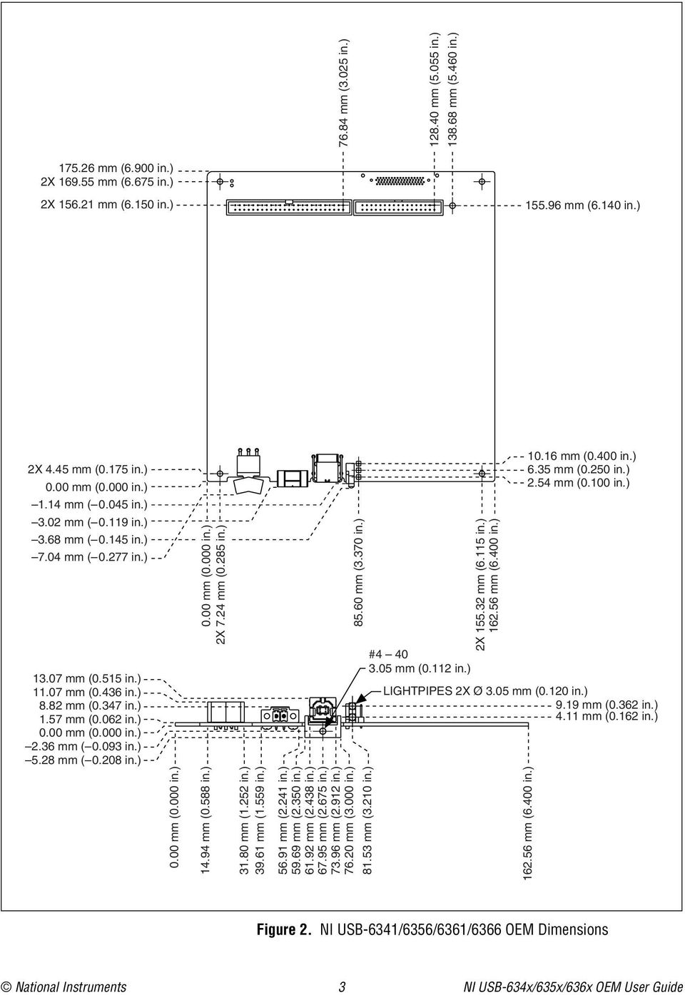
3 . mm (.00 in.) X. mm (. in.) X. mm (.0 in.). mm (.0 in.).0 mm (0. in.).0 mm (0. in.). mm (0. in.). mm (0.0 in.) 0.00 mm (0.000 in.). mm ( 0.0 in.). mm ( 0.0 in.).0 mm (.0 in.) # 0.0 mm (0. in.) X. mm (. in.). mm (.00 in.) 0. mm (0.00 in.). mm (0.0 in.). mm (0.00 in.) LIGHTPIPES X Ø.0 mm (0.0 in.). mm (0. in.). mm (0. in.) 0.00 mm (0.000 in.). mm (0. in.).0 mm (. in.). mm (. in.). mm (. in.). mm (.0 in.). mm (. in.). mm (. in.). mm (. in.).0 mm (.000 in.). mm (.0 in.). mm (.00 in.). mm (.0 in.).0 mm (.0 in.). mm (.0 in.) X. mm (0. in.) 0.00 mm (0.000 in.). mm ( 0.0 in.).0 mm ( 0. in.). mm ( 0. in.).0 mm ( 0. in.) 0.00 mm (0.000 in.) X. mm (0. in.) Figure. NI USB-/// OEM Dimensions National Instruments NI USB-x/x/x OEM User Guide
4 . mm (.00 in.) X. mm (. in.) X. mm (.0 in.) X. mm (. in.).0 mm (0. in.).0 mm (0. in.). mm (0. in.). mm (0.0 in.) 0.00 mm (0.000 in.). mm ( 0.0 in.). mm ( 0.0 in.) # 0.0 mm (0. in.) LIGHTPIPES X Ø.0 mm (0.0 in.). mm (0. in.). mm (0. in.) 0.00 mm (0.000 in.). mm (0. in.).0 mm (. in.). mm (. in. ). mm (. in.). mm (.0 in.). mm (. in.). mm (. in.). mm (. in.).0 mm (.000 in.). mm (.0 in.). mm (.00 in.) X. mm (.0 in.) X.0 mm (.0 in.). mm (.0 in.). mm (.0 in.) X. mm (0. in.) 0.00 mm (0.000 in.). mm ( 0.0 in.).0 mm ( 0. in.). mm ( 0. in.).0 mm ( 0. in.) 0.00 mm (0.000 in.) X. mm (0. in.).0 mm (.0 in.) X. mm (. in.). mm (.00 in.) 0. mm (0.00 in.). mm (0.0 in.). mm (0.00 in) Figure. NI USB-/ OEM Dimensions NI USB-x/x/x OEM User Guide ni.com

5 I/O Connector Pinouts Figures through show the connector pinouts for the NI USB- OEM, NI USB- OEM, NI USB-/ OEM, NI USB- OEM, and NI USB- OEM devices. Refer to the X Series User Manual at ni.com/manuals for more information about X Series OEM device signals and how to connect them. National Instruments NI USB-x/x/x OEM User Guide

6 0-Pin Digital Connector 0 PFI PFI PFI 0 PFI PFI PFI 0 0 PFI PFI PFI PFI PFI PFI PFI PFI 0 PFI PFI 0 P0. P0. P0. 0 P0. P0. P0. P0. P0.0 -Pin Analog Connector AI (AI ) AI (AI +) AI (AI ) 0 AI (AI +) AI (AI ) AI (AI +) AI (AI ) AI (AI +) AI (AI ) AI (AI +) 0 AI 0 (AI ) AI (AI +) AI (AI ) AI (AI +) AI (AI 0 ) 0 AI 0 (AI 0+) AI SENSE NC AO AO 0 NC = No Connect Figure. NI USB- OEM Connector Pinout NI USB-x/x/x OEM User Guide ni.com
 AI (AI +) AI (AI ) 0 AI (AI +) AI (AI ) AI (AI +) AI (AI ) AI (AI +) AI")
7 Bank 0-Pin Digital Connectors 0 0 Bank P0. P0.0 P0. P0. P0. P0. P0. P0. P0. P0. P0. P0.0 P0. P0. P PFI PFI PFI PFI PFI PFI 0 PFI PFI PFI PFI PFI PFI PFI PFI PFI P0. PFI 0 P0. P0. P0. P0. P0. P0. 0 P0. 0 P0. P0. P0. P0.0 P0. P0. P0. P0. P0.0 Bank -Pin Analog Connectors Bank AI (AI +) AI 0 (AI ) AI (AI +) AI (AI 0 ) AI (AI +) AI (AI ) AI (AI +) AI (AI ) AO AO AI (AI ) AI (AI +) AI (AI ) AI 0 (AI 0+) AI (AI ) AI (AI +) AI (AI ) AI (AI +) AI SENSE NC AI (AI +) AI (AI ) AI (AI +) AI (AI ) AI (AI +) AI 0 (AI ) AI (AI +) AI (AI 0 ) AO AO AI (AI ) AI (AI +) AI (AI ) AI (AI +) AI (AI ) AI (AI +) AI (AI ) AI 0 (AI 0+) AI SENSE NC NC = No Connect NC = No Connect Figure. NI USB- OEM Connector Pinout National Instruments NI USB-x/x/x OEM User Guide

8 0-Pin Digital Connector PFI PFI PFI PFI PFI PFI 0 PFI PFI PFI PFI PFI PFI PFI PFI PFI PFI 0 P0. P0. P0. P0. P0. P0. P0. P0.0 -Pin Analog Connector AI AI + AI 0 AI + AI AI + AI AI + AI AI + 0 AI AI + AI AI + AI 0 0 AI 0+ NC APFI 0 AO AO 0 NC = No Connect Figure. NI USB-/ OEM Connector Pinout NI USB-x/x/x OEM User Guide ni.com

9 0-Pin Digital Connector PFI PFI PFI PFI PFI PFI 0 PFI PFI PFI PFI PFI PFI PFI PFI PFI PFI 0 P0. P0. P0. P0. P0. P0. P0. P0.0 -Pin Analog Connector AI (AI ) AI (AI +) AI (AI ) 0 AI (AI +) AI (AI ) AI (AI +) AI (AI ) AI (AI +) AI (AI ) AI (AI +) 0 AI 0 (AI ) AI (AI +) AI (AI ) AI (AI +) AI (AI 0 ) 0 AI 0 (AI 0+) AI SENSE APFI 0 AO AO 0 Figure. NI USB- OEM Connector Pinout National Instruments NI USB-x/x/x OEM User Guide
 AI (AI +) 0 AI 0 (AI ) AI (AI +) AI (AI ) AI (AI +) AI (AI 0 ) 0 AI 0 (AI 0+) AI SENSE APFI 0 AO AO 0")
10 Bank 0-Pin Digital Connectors Bank P0. P0.0 P0. P0. P0. P0. P0. P0. P0. P0. P0. P0.0 P0. P0. P0. P0. P0. P0. P0. P0. P0. P0.0 P0. P PFI PFI PFI PFI PFI PFI 0 PFI PFI PFI PFI PFI PFI PFI PFI PFI PFI 0 P0. P0. P0. P0. P0. P0. P0. P0.0 Bank -Pin Analog Connectors Bank AI (AI +) AI 0 (AI ) AI (AI +) AI (AI 0 ) AI (AI +) AI (AI ) AI (AI +) AI (AI ) AO AO AI (AI ) AI (AI +) AI (AI ) AI 0 (AI 0+) AI (AI ) AI (AI +) AI (AI ) AI (AI +) AI SENSE APFI AI (AI +) AI (AI ) AI (AI +) AI (AI ) AI (AI +) AI 0 (AI ) AI (AI +) AI (AI 0 ) AO AO AI (AI ) AI (AI +) AI (AI ) AI (AI +) AI (AI ) AI (AI +) AI (AI ) AI 0 (AI 0+) AI SENSE APFI 0 Figure. NI USB- OEM Connector Pinout NI USB-x/x/x OEM User Guide 0 ni.com
 AI (AI ) AI (AI +) AI SENSE APFI AI (AI +) AI (AI ) AI (AI +) AI (AI ) AI (AI +) AI 0 (AI ) AI (AI +) AI (AI 0 ) AO AO 0 0 0 0 AI (AI ) AI (AI +) AI (AI ) AI (AI +) AI (AI ) AI")
11 Default NI-DAQmx Counter/Timer Pins By default, NI-DAQmx routes the counter/timer inputs and outputs to the PFI pins, shown in the following table. Counter/Timer Signal Default Terminal Name CTR 0 SRC PFI CTR 0 GATE PFI CTR 0 AUX PFI 0 CTR 0 OUT PFI CTR 0 A PFI CTR 0 Z PFI CTR 0 B PFI 0 CTR SRC PFI CTR GATE PFI CTR AUX PFI CTR OUT PFI CTR A PFI CTR Z PFI CTR B PFI CTR SRC PFI 0 CTR GATE PFI CTR AUX PFI CTR OUT PFI CTR A PFI 0 CTR Z PFI CTR B PFI CTR SRC PFI CTR GATE PFI CTR AUX PFI CTR OUT PFI CTR A PFI CTR Z PFI CTR B PFI FREQ OUT PFI National Instruments NI USB-x/x/x OEM User Guide

12 LEDs Attaching External LEDs NI USB-x/x/x OEM devices have two LEDs that reflect the device state. The ACTIVE LED (at reference designator DS) indicates activity over the bus. The READY LED (at reference designator DS) indicates whether or not the device is configured. Refer to the X Series User Manual for more information about LED behavior on the X Series OEM devices. If you are putting the NI USB-x/x/x OEM device in an enclosure, you can either seat the supplied lightpipe in the holes (at reference designators DS and DS) on the device, as shown in Figure, or attach external LEDs, as described in the Attaching External LEDs section. When the lightpipe is attached, the top LED is the ACTIVE LED, and the bottom LED is the READY LED. Three connectors on the device E, E, and E allow you to connect an external LED circuit to the device, as shown in Figure. To connect an external READY LED, use E as the positive connection () and E as the negative connection. To connect an external ACTIVE LED, use E as the positive connection and E as the negative connection. NI recommends that you limit the current to 0 ma per LED. You can limit this current by using external resistors, as shown in Figure. OEM (On-Board) Optional Lightpipe E E E E E E External READY LED External ACTIVE LED Figure. Schematic for External LED Circuits NI USB-x/x/x OEM User Guide ni.com

13 Power Switch The power switch on the NI USB-x/x/x OEM device powers the device on and off. Figure 0 shows the pins on the power switch and power circuitry. 00 kω to Ground VDC Out VDC In ON Switch 00 kω SW NC NC Connector J0 ON Power to Device SW 00 kω F J0 Power Connector Figure 0. Schematic for the Power Switch (Switch Shown in ON Position) Pin, VDC In, is connected to VDC through a non-user-replaceable fuse (reference designator F). The VDC is the voltage provided by the power supply through pin of the power connector (reference designator J0) and must be to 0 VDC, 0 W. Pin, VDC Out, provides power to the circuitry on the device. When the switch is in the ON position, the VDC power supply from pin is routed to pin. Pin, 00 kω to Ground, connects pin to ground through a 00 kω resistor when the switch is in the OFF position. National Instruments NI USB-x/x/x OEM User Guide
 and must be to 0 VDC, 0 W. Pin, VDC Out, provides power to the circuitry on the device.")
14 Connecting the NI USB-x/x/x OEM Device to Your Chassis The NI USB-x/x/x OEM device features five mounting holes, shown in Figure. Three of the mounting holes are plated for customer grounded connections. X Ø. mm (0. in.) Plated Mounting Hole Connected to Chassis Ground Mounting Hole Figure. Customer Mounting Holes (NI USB-// OEM Shown) NI USB-x/x/x OEM User Guide ni.com
 Plated Mounting Hole Connected to Chassis Ground Mounting Hole Figure.")
15 Device Components Component(s) Table contains information about the components used for interfacing and interacting with the X Series USB OEM devices. Table. X Series USB OEM Components Reference Designator(s) on PCB Manufacturer Manufacturer Part Number LEDs DS, DS, DS *,DS * SunLED XZBBW-TN Lightpipe Dialight -0F -pin connector(s) (USB-///) J M N-00RB (USB-/) J, J 0-pin connector(s) (USB-///) P M N0-00UB (USB-/) P, P USB connector J AMP 0- Power connector J0 Phoenix Contact Power switch SW C&K E0JAQE -pin connector(s) (USB-///) J Molex 0-00 (USB-/) J, J * Optional LED locations near the mass termination connectors. These are not populated by default. Optional mass termination connectors. These are not populated by default. National Instruments NI USB-x/x/x OEM User Guide
 J, J 0-pin connector(s) (USB-///) P M N0-00UB (USB-/) P, P USB connector J AMP 0- Power connector J0 Phoenix Contact Power switch SW C&K E0JAQE -pin connector(s) (USB-///) J Molex")

16 Modifying the OEM Device Name in Microsoft Windows You can change how the NI USB-x/x/x OEM device name appears in the Windows Device Manager when users install the device, as shown in Figure. Figure. NI USB- OEM Device USB DAQ in the Windows Device Manager (Windows Shown) To modify the device name in the Windows Device Manager in Microsoft Windows /Vista/XP, and in the Found New Hardware Wizard in Microsoft Windows XP, complete the following steps. Note You must have NI-DAQmx. or later installed on your PC.. Locate the OEMx.inf file in the y:\windows\inf\ directory, where x is the random number assigned to the INF file by Windows, and y:\ is the root directory where Windows is installed. Security updates to Microsoft /Vista/XP and NI-DAQmx create random INF files for NI hardware. Windows assigns random file numbers to all INF files, which causes the user to search through several INF files until the correct file is located. If you want to revert back, save a copy of this file as OEMx_original.inf in a different location. (Windows XP) You can change how the NI USB-x/x/x OEM device name appears when users install the device in both the Found New Hardware Wizard that appears when the device is initially installed and in the Windows Device Manager. NI USB-x/x/x OEM User Guide ni.com

17 . Edit the device INF file by opening OEMx.inf with a text editor. At the bottom of this file, in the [Strings] section, are the descriptors where Windows looks to identify the device. Locate the four lines of text that contain in quotes the descriptors for the device name you are modifying. Change the descriptor on all four lines to the new device name, as shown in Figure. Original File Modified File Figure. INF File Descriptors Changed to My Device (Windows Shown). Save and close the INF file.. Open the Windows Device Manager. (Windows /Vista) In the Device Manager, notice that the OEM device now appears as My Device, as shown in Figure. (Windows XP) In the Device Manager, right-click the OEM device under Data Acquisition Devices, and select Uninstall. Power down the OEM device and disconnect the USB cable from your PC. National Instruments NI USB-x/x/x OEM User Guide
 In the Device Manager, notice that the OEM device now appears as My Device, as shown in Figure.")
18 When you reconnect and power on the device, it appears as My Device in Windows Device Manager, as shown in Figure. Figure. My Device in the Windows Device Manager (Windows Shown) Note When the device is initially installed, Windows may display the following messages: USB DAQ detected!, and then USB DAQ: Device driver software installed successfully. These alert messages cannot be changed. Note Modifying the INF file will not change the NI USB-x/x/x OEM device name in Measurement & Automation Explorer (MAX). LabVIEW, National Instruments, NI, ni.com, the National Instruments corporate logo, and the Eagle logo are trademarks of National Instruments Corporation. Refer to the Trademark Information at ni.com/trademarks for other National Instruments trademarks. Other product and company names mentioned herein are trademarks or trade names of their respective companies. For patents covering National Instruments products/technology, refer to the appropriate location: Help»Patents in your software, the patents.txt file on your media, or the National Instruments Patent Notice at ni.com/patents. Refer to the Export Compliance Information at ni.com/legal/ export-compliance for the National Instruments global trade compliance policy and how to obtain relevant HTS codes, ECCNs, and other import/export data. 0 National Instruments. All rights reserved. 0B-0 Oct
. LabVIEW, National Instruments, NI, ni.")
NI USB-6008/6009 OEM USER GUIDE
 USER GUIDE NI USB-6008/6009 OEM This document provides information about the dimensions, connectors, and other components of the National Instruments USB-6008/6009 OEM device. For more information about
NI 653x Cable Adapter
 USER GUIDE NI 653x Cable Adapter Contents The NI 653x cable adapter interfaces with National Instruments high-speed digital I/O (DIO) devices. The cable adapter provides an easy way to connect the Very
INSTALLATION INSTRUCTIONS 160-Pin Cable for the NI PXI-2530B
 INSTALLATION INSTRUCTIONS 160-Pin Cable for the NI PXI-2530B Contents This guide describes how to connect and use the National Instruments 160-pin shielded cable for the NI PXI-2530B which has a maximum
NI-XNET Hardware and Software
 INSTALLATION GUIDE NI-XNET Hardware and Software This installation guide contains instructions to help you install your National Instruments hardware and software. Complete documentation is in the NI-XNET
Unpack and Install the Devices, Accessories, and Cables
 READ ME FIRST NI-DAQmx and DAQ Device Installation Guide Français Deutsch ni.com/manuals Install your software before installing new hardware. Install Application Software Install NI application software,
How To Write A Librao Low Voltage Differential (Lvds) Module On An Nio 6585 Fuserio (Flexrio) Power Supply (Femaleseo) And Power Supply On An Iphone Or Ip
 Module On An Nio 6585 Fuserio (Flexrio) Power Supply (Femaleseo) And Power Supply On An Iphone Or Ip") NI 6585 Specifications This document lists the specifications of the National Instruments 6585 FlexRIO low-voltage differential (LVDS) adapter module. Pair these specifications with your FPGA module specifications.
NI 6585 Specifications This document lists the specifications of the National Instruments 6585 FlexRIO low-voltage differential (LVDS) adapter module. Pair these specifications with your FPGA module specifications.
DAQ Getting Started Guide
 DAQ Getting Started Guide This guide describes how to confirm your NI data acquisition (DAQ) device is operating properly. Install your application and driver software, then your device, using the instructions
Set Up Your MXI -Express x4 System
 Set Up Your MXI -Express x4 System Terminology This document explains what you will need to set up various MXI-Express x4 hardware configurations. The products covered by this guide are the NI PCIe-8371/8372
Set Up Your MXI -Express x1 System
 Set Up Your MXI -Express x1 System Terminology This document explains what is needed to set up various MXI-Express x1 hardware configurations. The products covered by this guide are the NI PCI-8361, NI
NI USB-5681 RF Power Meter Specifications
 NI USB-568 RF Power Meter Specifications General This document lists specifications for the NI USB-568 RF power meter. Minimum or maximum specifications are warranted under the following conditions: hour
NI 6601/6602. Contents CALIBRATION PROCEDURE. ni.com/manuals
 CALIBRATION PROCEDURE NI 6601/6602 Français Deutsch ni.com/manuals This document contains information and instructions for calibrating the National Instruments 6601/6602 data acquisition devices. Contents
NI PXI-8232. Installing Your PXI Board INSTALLATION GUIDE
 INSTALLATION GUIDE NI PXI-8232 Installing Your PXI Board This document explains how to install the Ethernet and NI-488.2 drivers for your NI PXI-8232 (part number 189140x-02L, where x is D or higher).
NI 6034E/6035E/6036E Family Specifications
 NI 6034E/6035E/6036E Family Specifications This document lists the I/O terminal summary and specifications for the devices that make up the NI 6034E/6035E/6036E family of devices. This family includes
USB-6008/6009. Contents USER GUIDE. This user guide describes how to use the National Instruments USB-6008/6009 data acquisition (DAQ) devices.
 devices.") USER GUIDE USB-6008/6009 Contents This user guide describes how to use the National Instruments USB-6008/6009 data acquisition (DAQ) devices. Introduction... 2 Safety Guidelines... 3 Software... 5 Logging
USER GUIDE USB-6008/6009 Contents This user guide describes how to use the National Instruments USB-6008/6009 data acquisition (DAQ) devices. Introduction... 2 Safety Guidelines... 3 Software... 5 Logging
NI 9423. NI C Series Overview DATASHEET. 8-Channel Sinking Digital Input Module
 DATASHEET NI 9423 8-Channel Sinking Digital Input Module 8-channel, 100 µs digital input 24 V logic, sinking digital input Compatible with NI CompactDAQ counters 250 Vrms, CAT II isolation 10-position
Introduction to Data Acquisition
 Introduction to Data Acquisition Overview This tutorial is part of the National Instruments Measurement Fundamentals series. Each tutorial in this series, will teach you a specific topic of common measurement
Getting Started with the LabVIEW Mobile Module
 Getting Started with the LabVIEW Mobile Module Contents The LabVIEW Mobile Module extends the LabVIEW graphical development environment to Mobile devices so you can create applications that run on Windows
Analog Servo Drive 25A8
 Description Power Range NOTE: This product has been replaced by the AxCent family of servo drives. Please visit our website at www.a-m-c.com or contact us for replacement model information and retrofit
Coupling Microsoft Visio with NI Requirements Gateway
 Coupling Microsoft Visio with NI Requirements Gateway Contents This document explains how NI Requirements Gateway interfaces with Microsoft Visio. Use this document to familiarize yourself with the Visio
Using the NI 17xx Smart Camera Direct Drive Lighting Controller
 Using the NI 17xx Smart Camera Direct Drive Lighting Controller Overview The use of proper lighting is often overlooked when designing a machine vision application. More robust and accurate inspections
DAQ. NI SCB-68A User Manual. 68-Pin Shielded Connector Block. ni.com/manuals. NI SCB-68A User Manual. August 2012 375865A-01
 DAQ NI SCB-68A User Manual 68-Pin Shielded Connector Block NI SCB-68A User Manual Français Deutsch ni.com/manuals August 2012 375865A-01 Support Worldwide Technical Support and Product Information ni.com
Getting Started with the LabVIEW Mobile Module Version 2009
 Getting Started with the LabVIEW Mobile Module Version 2009 Contents The LabVIEW Mobile Module extends the LabVIEW graphical development environment to Mobile devices so you can create applications that
NI Real-Time Hypervisor for Windows
 QUICK START GUIDE NI Real-Time Hypervisor Version 2.1 The NI Real-Time Hypervisor provides a platform you can use to develop and run LabVIEW and LabVIEW Real-Time applications simultaneously on a single
CompactRIO crio-9052
 OPERATING INSTRUCTIONS CompactRIO crio-9052 CompactRIO StarFabric Interface 1 POWER BACKUP STATUS FPGA V1 C V2 2 C Rx INPUT 9 35 V 17 W MAX 3 Tx NI crio-9052 CompactRIO StarFabric Interface 1 LEDs 2 Power
This document lists specifications for the NI PXIe-4139 (NI 4139) precision system sourcemeasure
 precision system sourcemeasure") DEVICE SPECIFICATIONS NI PXIe-4139 Single-Channel Precision System SMU This document lists specifications for the NI PXIe-4139 (NI 4139) precision system sourcemeasure unit (SMU). Specifications are subject
DEVICE SPECIFICATIONS NI PXIe-4139 Single-Channel Precision System SMU This document lists specifications for the NI PXIe-4139 (NI 4139) precision system sourcemeasure unit (SMU). Specifications are subject
NI-DAQ mx Base 3.x. Contents GETTING STARTED GUIDE
 GETTING STARTED GUIDE NI-DAQ mx Base 3.x Contents This guide describes how to install and configure the NI-DAQmx Base 3.x software and a data acquisition (DAQ) device. This guide also describes how to
S-series Mass Connection Solutions
 DeltaV Distributed Control System Product Data Sheet March 2015 S-series Mass Connection Solutions Fast, easy and error-free cabinet wiring Modular design, improves reliability Lowers overall termination
NI 9475 8-Channel, 60 V, High-Speed, Sourcing Digital Output Module
 OPERATING INSTRUCTIONS AND SPECIFICATIONS NI 9475 8-Channel, 60 V, High-Speed, Sourcing Digital Output Module Français Deutsch ni.com/manuals This document describes how to use the National Instruments
Measurement Studio. Contents RELEASE NOTES
 RELEASE NOTES Measurement Studio Contents These release notes introduce Measurement Studio 8.1.2. Refer to this document for installation requirements, deployment requirements, installation instructions,
Measurement Studio. Contents RELEASE NOTES
 RELEASE NOTES Measurement Studio Contents These release notes introduce Measurement Studio 2010. Refer to this document for information about new features and functionality, installation requirements,
Installation Instructions
 Installation Instructions Windows USB driver for Installation If a Diagnostic Interface with USB is connected to a PC with a Windows operating system 98, ME, XP or Vista for the first time, it is necessary
CALIBRATION PROCEDURE NI 9219. Contents. Software Requirements. ni.com/manuals
 CALIBRATION PROCEDURE NI 9219 Français Deutsch ni.com/manuals Contents This document contains information for calibrating the National Instruments 9219. For more information on calibration, visit ni.com/calibration.
485USBTB-2W & 485USBTB-4W
 RS-485 2-Wire RS-485 4-Wire Connector Data Rate Connector Standard Data Rate Source Input Voltage Consumption Driver CD Dimensions Enclosure Weight Operating Temp Storage Temp Op Humidity MTBF MTBF Method
MAX6683 Evaluation System/Evaluation Kit
 19-2343; Rev 1; 3/07 MAX6683 Evaluation System/Evaluation Kit General Description The MAX6683 evaluation system (EV system) consists of a MAX6683 evaluation kit (EV kit) and a companion Maxim CMODUSB board.
Coupling Microsoft Excel with NI Requirements Gateway
 Coupling Microsoft Excel with NI Requirements Gateway Contents Using the Excel Type This document explains how NI Requirements Gateway interfaces with Microsoft Excel. Use this document to familiarize
Material: Weight: Bearing Life: Shaft Speed: Starting Torque: Mass Moment of Inertia: Shaft Loads:
 Automation / Mini Type SCH32F Hollow Shaft Encoder - Ø 32 mm Hollow Bore: Ø 6 mm to Ø 3/8 inch Resolution up to 5000 ppr IP 65 (IP 50 for IDC connector option) Electrical Specifications Code: Resolution:
RF Power Amplifier PA10W Owner s Manual SpinCore Technologies, Inc. http://www.spincore.com
 RF Power Amplifier PA10W Owner s Manual SpinCore Technologies, Inc. http://www.spincore.com Congratulations and thank you for choosing a design from SpinCore Technologies, Inc. We appreciate your business!
DS9490R/DS9490B USB to 1-Wire/iButton Adapters
 9-488; Rev 6/ FEATURES High-Speed Mbps Universal Serial Bus (USB) Interface Supports Standard and Overdrive -Wire Communication Slew-Rate-Controlled -Wire Timing and Active Pullup for Improved -Wire Network
Getting Started with the NI LabVIEW Embedded Module for ARM Microcontrollers
 Getting Started with the NI LabVIEW Embedded Module Contents The LabVIEW Embedded Module is a comprehensive graphical development environment for embedded design. This module seamlessly integrates the
USB I/O CONTROL BOX 8 relays, 8 digital I/O lines and 8 HV inputs
 USB I/O CONTROL BOX 8 relays, 8 digital I/O lines and 8 HV inputs The Big Deal USB HID device compatible with 32/64 Bit operating systems 8 TTL/LVTTL digital I/O channels, 8 High Voltage digital inputs
UIM2901-5A MACH3 breakout board
 User Manual UIM2901-5A MACH3 Breakout Board UIM2901-5A MACH3 Breakout Board UIM2901-5A MACH3 breakout board Features General DB25 interface between PC and user device Fully buffered opto-isolated I/O (Input
AC 800M. EtherNet/IP DeviceNet Linking Device LD 800DN. Power and productivity for a better world TM SP1134
 AC 800M EtherNet/IP DeviceNet Linking Device LD 800DN SP1134 Power and productivity for a better world TM AC 800M EtherNet/IP DeviceNet Linking Device LD 800DN NOTICE This document contains information
NI 9211 Datasheet DATASHEET. 4 TC, ±80 mv, 24 Bit, 14 S/s Aggregate
 DATASHEET NI 9211 Datasheet 4 TC, ±80 mv, 24 Bit, 14 S/s Aggregate Screw-terminal connectivity 50 Hz/60 Hz noise rejection 250 Vrms, CAT II, channel-to-earth isolation The NI 9211 thermocouple input module
CAUTION! THE 7I29 USES VOLTAGE AND POWER LEVELS THAT REPRESENT A HAZARD TO LIFE AND LIMB.
 7I29 MANUAL Rev 1.5 CAUTION! THE 7I29 USES VOLTAGE AND POWER LEVELS THAT REPRESENT A HAZARD TO LIFE AND LIMB. THE 7I29 IS INTENDED FOR USE BY OEMS THAT WILL INTEGRATE IT INTO A SYSTEM WITH INTERLOCKS AND
UniPi technical documentation REV 1.1
 technical documentation REV 1.1 Contents Overview... 2 Description... 3 GPIO port map... 4 Power Requirements... 5 Connecting Raspberry Pi to UniPi... 5 Building blocks... 5 Relays... 5 Digital Inputs...
Universal Serial Bus (USB) to DH-485 Interface Converter
 to DH-485 Interface Converter") Installation Instructions Universal Serial Bus (USB) to DH-485 Interface Converter Catalog Number 1747-UIC Contents Overview..................................................3 Computer and Operating System
Installation Instructions Universal Serial Bus (USB) to DH-485 Interface Converter Catalog Number 1747-UIC Contents Overview..................................................3 Computer and Operating System
How To Power A Schen
 Automation / Mini Type SCH32F Hollow Shaft Encoder - Ø 32 mm Hollow Bore: Ø 6 mm to Ø 3/8 inch Resolution up to 5000 ppr IP 65 (IP 50 for IDC connector option) Electrical Specifications Code: Resolution:
Servo Motors (SensorDAQ only) Evaluation copy. Vernier Digital Control Unit (DCU) LabQuest or LabPro power supply
 Evaluation copy. Vernier Digital Control Unit (DCU) LabQuest or LabPro power supply") Servo Motors (SensorDAQ only) Project 7 Servos are small, relatively inexpensive motors known for their ability to provide a large torque or turning force. They draw current proportional to the mechanical
Servo Motors (SensorDAQ only) Project 7 Servos are small, relatively inexpensive motors known for their ability to provide a large torque or turning force. They draw current proportional to the mechanical
Features, Benefits, and Operation
 Features, Benefits, and Operation 2014 Decibel Eleven Contents Introduction... 2 Features... 2 Rear Panel... 3 Connections... 3 Power... 3 MIDI... 3 Pedal Loops... 4 Example Connection Diagrams... 5,6
USB-QUAD08. Eight-channel Quadrature Encoder Input Device. Specifications
 Eight-channel Quadrature Encoder Input Device s Document Revision 1.1 May 2012 Copyright 2012 s All specifications are subject to change without notice. Typical for 25 C unless otherwise specified. s in
ECONseries Low Cost USB DAQ
 ECONseries Low Cost USB Data Acquisition Modules ECONseries Low Cost USB DAQ The ECONseries is a flexible yet economical series of multifunction data acquisition modules. You choose the number of analog
NI USB-9215 Series. Introduction USER GUIDE AND SPECIFICATIONS. 4-Channel, ±10 VDC, 16-Bit Simultaneous Sampling Analog Input Devices
 USER GUIDE AND SPECIFICATIONS NI USB-9215 Series 4-Channel, ±10 VDC, 16-Bit Simultaneous Sampling Analog Input Devices Introduction This user guide describes how to use the National Instruments USB-9215
USBSPYDER08 Discovery Kit for Freescale MC9RS08KA, MC9S08QD and MC9S08QG Microcontrollers User s Manual
 USBSPYDER08 Discovery Kit for Freescale MC9RS08KA, MC9S08QD and MC9S08QG Microcontrollers User s Manual Copyright 2007 SofTec Microsystems DC01197 We want your feedback! SofTec Microsystems is always on
1-Port R422/485 Serial PCIe Card
 1-Port R422/485 Serial PCIe Card Installation Guide 1. Introduction Thank you for purchasing this 1-Port RS422/485 Serial PCI Express (PCIe) Card. It is a universal add in card that connects to a PC or
How to install USB driver (MICRO/I)
") How to install USB driver (MICRO/I) Install on Windows XP 1. Connect the USB port on HG3G series and the USB port on PC. 2. Windows displays Found new Hardware Wizard. Select No, not this time and press
How to install USB driver (MICRO/I) Install on Windows XP 1. Connect the USB port on HG3G series and the USB port on PC. 2. Windows displays Found new Hardware Wizard. Select No, not this time and press
M68EVB908QL4 Development Board for Motorola MC68HC908QL4
 M68EVB908QL4 Development Board for Motorola MC68HC908QL4! Axiom Manufacturing 2813 Industrial Lane Garland, TX 75041 Email: Sales@axman.com Web: http://www.axman.com! CONTENTS CAUTIONARY NOTES...3 TERMINOLOGY...3
SAFEPATH 4 Telephone Zone Controller
 SAFEPATH 4 Telephone Zone Controller SP4-TZC P/N 109921 SP4-TZC-P P/N 105590 Installation, Testing, Operation and Maintenance Manual 273 Branchport Avenue, Long Branch, NJ 07740-6899 Ph: (800) 631-2148
FIELDPOINT BUS EXTENDER CABLE
 INSTALLATION GUIDE FIELDPOINT BUS EXTENDER CABLE If you have space constraints, you can use the FieldPoint Bus Extender Cable to mount a FieldPoint bank in two or three rows. Caution You should not use
3M Wrist Strap and Footwear Tester 740. User s Guide
 3M Wrist Strap and Footwear Tester 740 User s Guide Table of Contents Section Page Safety Information...3 1.0 General...4 2.0 Description...4 3.0 Operation...5 4.0 Wall Mounting...5 5.0 Wrist Strap Test...6
USB-Blaster Download Cable User Guide
 USB-Blaster Download Cable User Guide Subscribe UG-USB81204 101 Innovation Drive San Jose, CA 95134 www.altera.com TOC-2 Contents Introduction to USB-Blaster Download Cable...1-1 USB-Blaster Revision...1-1
1. How to install CDM driver on PC for Lambda devices
 1. How to install CDM driver on PC for Lambda devices This installation guide is based on Window XP. Different systems may require different actions on some steps. All Lambda devices (Lambda 10-3, 10B,
About Measurement Studio
 RELEASE NOTES Measurement Studio These release notes introduce Measurement Studio 2012. Refer to this document for information about installation requirements, driver support version information, installation
www.curtisinstruments.com
 CANBUS I/O EXPANSION MODULE MODELS 56 / 56P FEATURES Eighteen multi-purpose I/O pins provide simple, flexible vehicle control system expansion. Two high-frequency (A, A) PWM driver outputs support a variety
ni.com/manuals Feature NI USB-6008 NI USB-6009 14 bits differential, 13 bits single-ended Maximum AI sample rate, 10 ks/s 48 ks/s
 USER GUIDE NI USB-6008/6009 Bus-Powered Multifunction DAQ USB Device Français Deutsch 日 本 語 한국어 简 体 中 文 ni.com/manuals The National Instruments USB-6008/6009 devices provide eight single-ended analog input
PoNET kbd48cnc. User s manual
 PoNET kbd48cnc User s manual Version: 16/10/2012 SAFETY INFORMATION! This product is intended for integration by the user into a computer numerical control (CNC) machine. It is the user's responsibility
Installation Guide for RadioLabs USB Wifi Antennas/Adapters
 1 Installation Guide for RadioLabs USB Wifi Antennas/Adapters 2 PLEASE READ BEFORE ATTEMPTING INSTALLATION Thank you for purchasing a RadioLabs USB wireless networking product. This document will guide
Safety Precautions WARNINGS
 Safety Precautions This guide contains a variety of safety markings related to the safe and correct operation of the USB Data Transfer Cable. Be sure to read this guide and any related manuals carefully
EMBEDDED ACCESS CONTROL Hardware Installation Guide
 EMBEDDED ACCESS CONTROL Hardware Installation Guide Lenel goentry Hardware Installation Guide, product version 1.00. This guide is item number DOC- ENHW-ENU, revision 1.003, April 2009 Copyright 2009 Lenel
Berkeley Audio Design Alpha USB
 QUICK USER GUIDE v1.2.2 Berkeley Audio Design Alpha USB The Alpha USB is an asynchronous High Speed USB to digital audio interface designed to provide the highest possible audio quality from computer audio
Getting Started Manual
 Getting Started Manual LabVIEW LEGO MINDSTORMS NXT Module The LabVIEW LEGO MINDSTORMS NXT Module enables you to perform the following tasks: Develop LabVIEW VIs that run on a host computer and communicate
Installation Guide for RadioLabs USB Wifi Antennas/Adapters
 1 Installation Guide for RadioLabs USB Wifi Antennas/Adapters 2 PLEASE READ BEFORE ATTEMPTING INSTALLATION Thank you for purchasing a RadioLabs USB wireless networking product. This document will guide
2-Port RS232/422/485 Combo Serial PCI Card
 2-Port RS232/422/485 Combo Serial PCI Card Installation Guide 1. Introduction Thank you for purchasing this 2-Port RS232/422/485 Combo Serial PCI Card. It is a universal add in card that connects to a
PCAN-ISA. CAN Interface for ISA. User Manual
 PCAN-ISA CAN Interface for ISA User Manual Products taken into account Product Name Model Item Number PCAN-ISA Single Channel One CAN channel IPEH-002074 PCAN-ISA Dual Channel Two CAN channels IPEH-002075
+Denotes lead-free and RoHS-compliant.
 19-4040; Rev 0; 2/08 MAX7474 Evaluation Kit General Description The MAX7474 evaluation kit (EV kit) is a fully assembled and tested printed-circuit board (PCB) that configures the MAX7474 IC for automatically
NEW. EVEN MORE data acquisition and test stand automation
 NEW EVEN MORE data acquisition and test stand automation the new class of data The plug&play complete package User benefits Expert Series is the latest generation of data acquisition Complete hardware
DCS Input/Output Relay Card Series
 Input/Output Relay Card Series I/O RELAY CARD (with loopback test function) 8N The 8N series I/O Relay Cards easily and quickly standardize and facilitate installation of the relay board. Loopback test
Advanced Data Capture and Control Systems
 Advanced Data Capture and Control Systems Tronisoft Limited Email: sales@tronisoft.com Web: www.tronisoft.com RS232 To 3.3V TTL User Guide RS232 to 3.3V TTL Signal Converter Modules P/N: 9651 Document
Silvertel. Ag5200. 1 Features. 2 Description. Power-over-Ethernet Plus Module. IEEE802.3at and IEEE802.3af compliant. Maximum 30W output power
 Silvertel V1.1 November 2012 Datasheet Pb 1 Features IEEE802.3at and IEEE802.3af compliant Maximum 30W output power Dual In-Line (DIL) package size 50.6mm (L) x 30mm (W) Overload, short-circuit and thermal
Cable Connection Procedures for Cisco 1900 Series Routers
 CHAPTER 5 Cable Connection Procedures for Cisco 1900 Series Routers This document describes how to connect your Cisco 1941 integrated services router to a power source and to networks and external devices.
Kvaser Mini PCI Express User s Guide
 Kvaser Mini PCI Express User s Guide Copyright 2013-2014 Kvaser AB, Mölndal, Sweden http://www.kvaser.com Printed Sunday 28 th September, 2014 We believe that the information contained herein was accurate
ELAN DIGITAL SYSTEMS LTD. SL232 PC- CARD USER S GUIDE
 ELAN DIGITAL SYSTEMS LTD. LITTLE PARK FARM ROAD, SEGENSWORTH WEST, FAREHAM, HANTS. PO15 5SJ. TEL: (44) (0)1489 579799 FAX: (44) (0)1489 577516 e-mail: support@pccard.co.uk website: http://www.pccard.co.uk
2-Port RS232/422/485 Combo Serial to USB2.0 Adapter (w/ Metal Case and Screw Lock Mechanism) Installation Guide
 Installation Guide") 2-Port RS232/422/485 Combo Serial to USB2.0 Adapter (w/ Metal Case and Screw Lock Mechanism) Installation Guide 1. Introduction Thank you for purchasing this 2-Port RS232/422/485 Combo Serial to USB Adapter.
2-Port RS232/422/485 Combo Serial to USB2.0 Adapter (w/ Metal Case and Screw Lock Mechanism) Installation Guide 1. Introduction Thank you for purchasing this 2-Port RS232/422/485 Combo Serial to USB Adapter.
OEM-EP Pressure Controllers
 Pressure Controllers Typical Applications Carrier Gas Pressure Control Air over Liquid Control Mass Spectrometer Process Gas Supply Pressure Control Miniature ler The Miniature ler converts a variable
CAN & LIN Development Tool CLDT1004 HS CAN
 HW Features : 1 x High Speed CAN Bus up to 1 Mbit/s 4 x digital Signal Output / Trigger Output easy synchronization between CAN Messages and physical HW Outputs SW Features : Can Bus Analyzing Tool Can
RealSSD Embedded USB Mass Storage Drive MTFDCAE001SAF, MTFDCAE002SAF, MTFDCAE004SAF, MTFDCAE008SAF
 RealSSD Embedded USB Mass Storage Drive MTFDCAE001SAF, MTFDCAE002SAF, MTFDCAE004SAF, MTFDCAE008SAF Embedded USB Mass Storage Drive Features Features Micron NAND Flash Interface: Universal Serial Bus (USB)
Options for ABB drives, converters and inverters. User s manual FDPI-02 diagnostics and panel interface
 Options for ABB drives, converters and inverters User s manual FDPI-02 diagnostics and panel interface Table of contents Table of contents 3 1. FDPI-02 diagnostics and panel interface Safety..............................................
WinLIN Setup and Operation:
 Frequently Asked Questions about the 07551-Series Masterflex L/S Computer-Compatible drives and about the Masterflex WinLIN Linkable Instrument Control Software (07551-70) WinLIN Setup and Operation: Will
Technical Specifications: The specifications represent a particular hardware platform. Application-specific software is provided.
 Preliminary TECHNICAL DATASHEET #TDAX020700 HYDRAULIC VALVE CONTROLLER 24 I/O 5 Analog and 6 Digital Inputs 1 Temperature Sensor and 1 RPM Sensor Interface 2 PWM Inputs 6 Proportional and 4 ON/OFF Current
NI InsightCM Server Version 1.0
 GETTING STARTED NI InsightCM Server Version 1.0 This document contains step-by-step instructions for the setup tasks you must complete to connect an NI Condition Monitoring System to NI InsightCM Server
SYSTEM 4C. C R H Electronics Design
 SYSTEM 4C C R H Electronics Design SYSTEM 4C All in one modular 4 axis CNC drive board By C R Harding Specifications Main PCB & Input PCB Available with up to 4 Axis X, Y, Z, A outputs. Independent 25
LabVIEW Report Generation Toolkit for Microsoft Office User Guide
 LabVIEW Report Generation Toolkit for Microsoft Office User Guide Version 1.1 Contents The LabVIEW Report Generation Toolkit for Microsoft Office provides tools you can use to create and edit reports in
Installation guide H-5500-8554-03-A. HSI hardwired system interface
 Installation guide H-5500-8554-03-A HSI hardwired system interface 2008-2011 Renishaw plc. All rights reserved. This document may not be copied or reproduced in whole or in part, or transferred to any
LabVIEW Report Generation Toolkit for Microsoft Office
 USER GUIDE LabVIEW Report Generation Toolkit for Microsoft Office Version 1.1.2 Contents The LabVIEW Report Generation Toolkit for Microsoft Office provides VIs and functions you can use to create and
Modular I/O System Analog and Digital Interface Modules
 OPERATING INSTRUCTIONS Modular I/O System Analog and Digital Interface Modules Installation Operation Maintenance Document Information Document ID Title: Operating Instructions Modular I/O System Part
Transmitter Interface Program
 Transmitter Interface Program Operational Manual Version 3.0.4 1 Overview The transmitter interface software allows you to adjust configuration settings of your Max solid state transmitters. The following
MAX17061A Evaluation Kit/Evaluation System
 19-4654; Rev 0; 5/09 MAX17061A Evaluation Kit/Evaluation System General Description The MAX17061A evaluation system (EV system) consists of the MAX17061A evaluation kit (EV kit) and the Maxim CMAXQUSB+
Series LC6D/LC6C. To power supply PLC. LC6C dedicated teaching box P.971. Options P.973
 Series LCD To power supply Electric Actuator Series LCC Stepper Motor Driver LCD Series LX Dedicated Stepper Motor Driver and Positioning Driver Series LCD/LCC PLC Positioning unit (Not incl. To be provided
Whale 3. User Manual and Installation Guide. DC Servo drive. Contents. 1. Safety, policy and warranty. 1.1. Safety notes. 1.2. Policy. 1.3. Warranty.
 Whale 3 DC Servo drive User Manual and Installation Guide Contents 1. Safety, policy and warranty. 1.1. Safety notes. 1.2. Policy. 1.3. Warranty. 2. Electric specifications. 2.1.Operation ranges. 3. Connections
TS510 & TS500. Installation & User Guide. Compatible Equipment
 Installation & User Guide Compatible Equipment TS510 REM - Remote Keypad 9040 - Loudspeaker DC54/58 - Digital Communicator SD1+ - Speech Dialler 496525 Issue A 1 of 10 TS510 and TS500 Overview Introduction
DOSISYS. Hands Free Reader LDM 210 - LDM 220. User Manual 127356A
 DOSISYS LDM 210 - LDM 220 Hands Free Reader User Manual 127356A Publication, translation and reproduction total or partial of this document is strictly forbidden without authorization MGP Instruments