EP A1 (19) (11) EP A1 (12) EUROPEAN PATENT APPLICATION. (43) Date of publication: Bulletin 2009/51
|
|
|
- Irene Norton
- 7 years ago
- Views:
Transcription
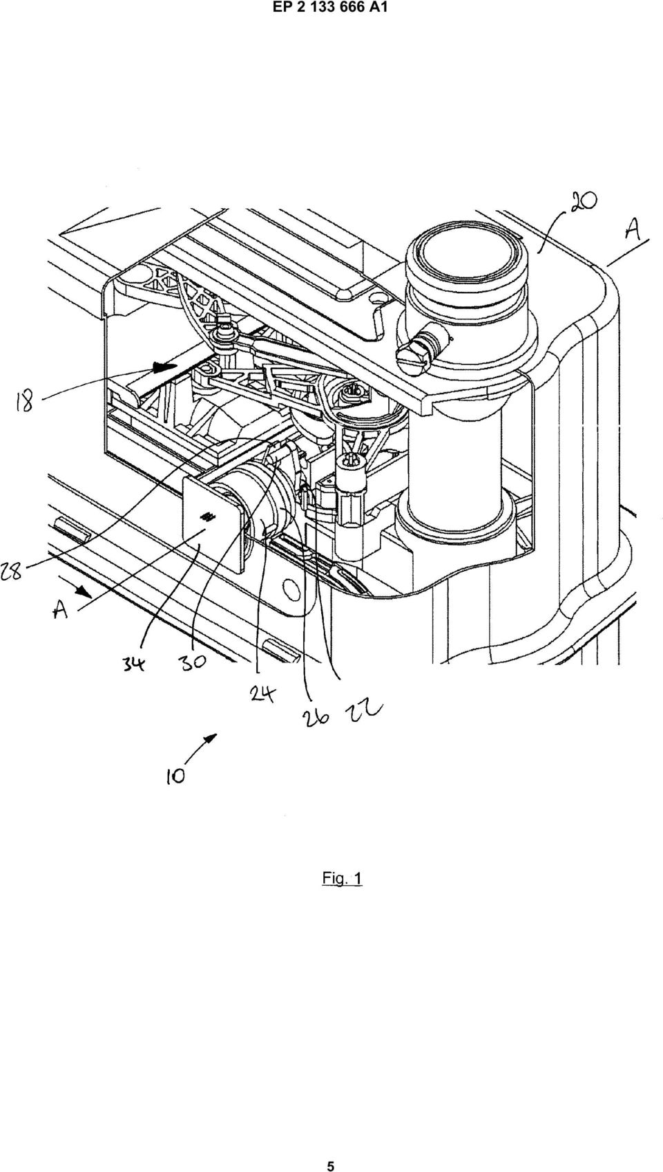
1 (19) (12) EUROPEAN PATENT APPLICATION (11) EP A1 (43) Date of publication: Bulletin 2009/51 (21) Application number: (51) Int Cl.: G01F 1/075 ( ) G01F 1/115 ( ) G01F 3/22 ( ) (22) Date of filing: (84) Designated Contracting States: AT BE BG CH CY CZ DE DK EE ES FI FR GB GR HR HU IE IS IT LI LT LU LV MC MT NL NO PL PT RO SE SI SK TR Designated Extension States: AL BA MK RS (71) Applicant: George Wilson Industries Limited Aldermans Green Industrial Estate Aldermans Green, Coventry Warwickshire CV2 2LD (GB) (72) Inventor: Wurtzler, David Coventry, Warwickshire CV2 2LD (GB) (74) Representative: Molony, Anna Chapman Molony Thorpe House 17 Dormer Place Leamington Spa CV32 5AA (GB) Remarks: Amended claims in accordance with Rule 137(2) EPC. (54) Diaphragm flow meter with rotating magnets (57) A diaphragm gas meter 10 comprising two fluid paths through front and rear diaphragm pans. Reciprocating movement of the diaphragms is converted into rotational movement of a drive shaft. Four permanent magnets, 14, 16 are provided in a mounting drum 24, coupled to the drive shaft and mounted for rotation about a sensor drum 32 formed in the meter case 20. A Hall effect probe 12 is provided adjacent the internal wall of the sensor drum 32. As gas flows through the meter 10, the magnets 14, 16 rotate about the sensor drum 32, exposing the Hall effect probe 12 to a changing magnetic field. The Hall probe 12 generates a Hall voltage, which changes sign according to the polarity of the magnetic field. The changing Hall voltage is detected by an electronic index circuit (34). EP A1 Printed by Jouve, PARIS (FR)
 (22) Date of filing: 09.06.")
2 1 EP A1 2 Description [0001] The invention relates to a fluid meter, and in particular, but not exclusively, to a gas meter. [0002] There are several known types of gas meter, which convert volumes of gas flow into movement of a mechanical counter. Such meters require the customer or a meter reader to physically inspect the meter to read the counter. It is desirable to be able to accurately and remotely read a gas meter, to thereby reduce the costs involved with meter reading and to provide accurate billing to customers. [0003] According to an aspect of the invention there is provided a fluid meter comprising: a fluid flow path; a fluid engagement member provided in the fluid flow path and adapted to be driven by a fluid flow; a magnetic field sensor; a plurality of magnets including at least one northpole and one south-pole mounted for rotational movement about the sensor; and drive transfer means coupled between the fluid engagement member and the magnets, such that fluid flow is converted into rotation of the magnets about the sensor, such that the sensor detects corresponding changes in the sense of the magnetic field to which it is exposed [0004] The magnetic field sensor preferably comprises a Hall effect sensor, which most preferably comprises a Hall effect probe having its output connected to a signal conditioning circuit. The Hall effect sensor thereby produces a high or low logic level output signal dependent upon the polarity of the magnetic field passing through the Hall effect probe. The magnetic field sensor is preferably offset from the axis of rotation of the magnets. The magnetic field sensor is thereby exposed to the magnetic field of the magnet passing closest to it. The output signal of the Hall effect sensor is preferably coupled to an electronic index means, most preferably an electronic counter integrated circuit device. The electronic index means converts the varying high/low output voltage from the Hall effect sensor into a digital count which may then be converted into an equivalent fluid volume. [0005] Preferably, the fluid meter further comprises a meter casing, the fluid flow path, fluid engagement member, magnets and drive transfer means being provided within the meter casing and the magnetic field sensor being provided outside the meter casing. The meter casing preferably comprises a sensor barrel projecting into the meter casing and defining a sensor socket, the magnetic field sensor being provided within the sensor socket and the magnets being mounted for rotational movement about the sensor barrel. The axis of rotation of the magnets is preferably generally co-axial with the longitudinal axis of the sensor barrel. The magnetic field sensor is preferably located adjacent to the wall of the sensor barrel, being the internal wall of the sensor socket. [0006] Preferably, the fluid meter comprises four permanent magnets general equally spaced about a common axis of rotation. The magnets are preferably provided on a mounting drum, the drum being mounted for rotation around the sensor barrel. The magnets are preferably arranged in a north-pole, south-pole, north-pole, south-pole configuration around the drum. [0007] The drive transfer means preferably comprises a drive shaft, coupled at one end to the mounting drum. The fluid engagement member preferably comprises a diaphragm, an impeller or a turbine. [0008] A plurality of fluid flow paths may be provided, with a corresponding plurality of fluid engagement members located therein. [0009] Where the or each fluid engagement member comprises a diaphragm, the drive transfer means preferably further comprises drive conversion means coupled to the diaphragm and adapted to convert reciprocating linear movement of the diaphragm into rotational movement. [0010] The fluid is preferably natural gas. [0011] An embodiment of the invention will now be described in detail, by way of example only, with reference to the accompanying drawings, in which: Figure 1 is a diagrammatic part cut-away representation of a diaphragm gas meter according to an embodiment of the invention; and Figure 2 is a diagrammatic part-sectional view along line A-A of Figure 1. [0012] Referring to the drawings, an embodiment of the invention provides a gas meter 10 comprising two fluid paths, a Hall effect probe 12, four permanent magnets, 14, 16 (only two are shown) and drive transfer means 18. [0013] The gas meter 10 is a diaphragm gas meter, having two gas flow paths through front and rear diaphragm pans. The first and second fluid engagement members comprise the diaphragms provided within the front and rear diaphragm pans. The arrangement of the diaphragm pans, diaphragms, and gas inlet and outlet valves is the same as in conventional diaphragm gas meters, which will be well known to the person skilled in the art and so will not be described in detail here. [0014] The drive transfer means 18 comprises a conventional arrangement of flags coupled to the diaphragms, flag rods and arms, and coupling cranks and gears adapted to convert the reciprocating movement of the diaphragm into rotation of the drive shaft 20. The arrangement of flags, flag rods and arms, and cranks and gears is the same as in a conventional diaphragm gas meter and so will be well known to the person skilled in the art. [0015] The gas flow paths, diaphragm pans, diaphragms and drive transfer means 18 are provided inside 2

3 3 EP A1 4 the meter s mild steel case 20. As will be well known to the person skilled in the art, the reciprocating movement of the diaphragms within the diaphragm pans is converted and transferred by the drive transfer means 18 into rotation of a drive shaft 22, which completes one full revolution for each cyclic volume (dependent on meter size) of gas that passes through the meter 10. [0016] The magnets 14, 16 are mounted within a mounting drum 24, which is mounted at one end in a mounting cup 26. A coupling tab 28 is provided on the external surface of the mounting cup 26. The magnets 14, 16 are provided in an alternating north-pole, southpole, north-pole, south-pole arrangement around the central axis of the mounting drum 24. [0017] The axis of the drive shaft 22 is aligned with the axis of the mounting drum 24, and thus the axis of rotation of the magnets 14, 16. The drive shaft 22 is provided with a coupling arm 30 at its distal end which is adapted to engage with and drive the coupling tab 28 on the mounting cup 26. Rotation of the drive shaft 22 is thereby coupled and transferred into rotation of the mounting cup 26 and the magnets 14, 16. [0018] The meter case 20 is provided with a stainless steel sensor barrel 32 which is riveted into the mild steel case 20, and projects internally into the case 20. The mounting drum 24 is located on the sensor barrel 32, such that it closely fits on the sensor barrel 32 but is free to rotate about the sensor barrel. The sensor barrel 32 acts to couple the magnetic fields of the magnets 14, 16 to the outside of the meter case 20. [0019] The Hall effect probe 12 is mounted inside the stainless steel barrel 32, adjacent the barrel wall. The Hall effect probe 12 is thereby located within the magnetic field between subsequent pairs of north and south poles of the magnets 14, 16, as the magnets 14, 16 rotate about the sensor barrel 32. The Hall effect probe 12 is therefore exposed to a changing magnetic field, the polarity of the magnetic field to which the Hall effect probe is exposed alternating as the magnets 14, 16 rotate about the sensor barrel 32; the Hall effect probe alternatingly being located between a north pole and a south pole, then a south pole and a north pole, and so on. The sign of the output Hall voltage generated by the Hall effect probe correspondingly changes, from positive to negative. The output of the Hall effect probe is interfaced to a power source and conditioning circuit 34, to together form a Hall effect sensor, which converts the output Hall voltage signal into a high or low logic level electrical output signal, dependent upon the polarity of the magnetic field passing through it. The Hall effect sensor therefore outputs an alternating high-low signal is that corresponds with the cyclic movement of the magnets 14, 16. [0020] The high/low logic level output signal from the Hall effect sensor is coupled to an electronic index, which is preferably an electronic counter IC chip. The electronic index counts the number of high and low output signals and is operable to convert the count into the equivalent volume of gas that has passed through the meter 10. The meter 10 thereby provides a digital gas data usage measurement. The meter 10 may additionally be provided with signal transmission means, of the type provided on remotely readable electricity meters for example, such that the meter may be interrogated and the gas usage data read remotely. Claims 1. A fluid meter (10) comprising: a fluid flow path; a fluid engagement member provided in the fluid flow path and adapted to be driven by a fluid flow; a magnetic field sensor (12); a plurality of magnets (14, 16) including at least one north-pole and one south-pole mounted for rotational movement about the sensor; and drive transfer means(18) coupled between the fluid engagement member and the magnets, such that fluid flow is converted into rotation of the magnets about the sensor, such that the sensor detects corresponding changes in the sense of the magnetic field to which it is exposed. 2. A fluid meter as claimed in claim 1, wherein the magnetic field sensor comprises a Hall effect sensor (12). 3. A fluid meter as claimed in claim 2, wherein the output signal of the Hall effect sensor is coupled to an electronic index means. 4. A fluid meter as claimed in any preceding claim, wherein the fluid meter further comprises a meter casing (20), the fluid flow path, fluid engagement member, magnets and drive transfer means being provided within the meter casing and the magnetic field sensor being provided outside the meter casing. 5. A fluid meter as claimed in claim 4, wherein the meter casing comprises a sensor barrel (32) projecting into the meter casing and defining a sensor socket, the magnetic field sensor being provided within the sensor socket and the magnets being mounted for rotational movement about the sensor barrel. 6. A fluid meter as claimed in claim 5, wherein the axis of rotation of the magnets is generally co-axial with the longitudinal axis of the sensor barrel and the magnetic field sensor is located adjacent to the wall of the sensor barrel. 7. A fluid meter as claimed in claim 6, wherein the fluid meter comprises four permanent magnets general equally spaced about a common axis of rotation. 3

4 5 EP A A fluid meter as claimed in claim 7, wherein the magnets are provided on a mounting drum (24) arranged in a north-pole, south-pole, north-pole, south-pole configuration around the drum, the drum being mounted for rotation around the sensor barrel. 9. A fluid meter as claimed in claim 8, wherein the drive transfer means comprises a drive shaft (22), coupled at one end to the mounting drum (24). 10. A fluid meter as claimed in any preceding claim, wherein the fluid engagement member comprises a diaphragm, an impeller or a turbine. 11. A fluid meter as claimed in any preceding claim, wherein a plurality of fluid flow paths are provided, with a corresponding plurality of fluid engagement members located therein. 12. A fluid meter as claimed in claims 11 or 12, wherein where the or each fluid engagement member comprises a diaphragm, the drive transfer means further comprises drive conversion means coupled to the diaphragm and adapted to convert reciprocating linear movement of the diaphragm into rotational movement characterized in that the axis of rotation of the magnets is generally co-axial with the longitudinal axis of the sensor barrel and the magnetic field sensor is located adjacent to the wall of the sensor barrel. 2. A fluid meter as claimed in claim 1, wherein the magnetic field sensor comprises a Hall effect sensor (12). 3. A fluid meter as claimed in claim 2, wherein the output signal of the Hall effect sensor is coupled to an electronic index means. 4. A fluid meter as claimed in any preceding claim, wherein the fluid meter comprises four permanent magnets general equally spaced about a common axis of rotation. 5. A fluid meter as claimed in claim 4, wherein the magnets are provided on a mounting drum (24) arranged in a north-pole, south-pole, north-pole, south-pole configuration around the drum, the drum being mounted for rotation around the sensor barrel. 6. A fluid meter as claimed in claim 5, wherein the drive transfer means comprises a drive shaft (22), coupled at one end to the mounting drum (24). 13. A fluid meter as claimed in any preceding claim, wherein the fluid is natural gas A fluid meter as claimed in any preceding claim, wherein the fluid engagement member comprises a diaphragm, an impeller or a turbine. Amended claims in accordance with Rule 137(2) EPC. 1. A fluid meter (10) comprising: A fluid meter as claimed in any preceding claim, wherein a plurality of fluid flow paths are provided, with a corresponding plurality of fluid engagement members located therein. a meter casing comprising a sensor barrel (32) projecting into the casing and defining a sensor socket; a fluid flow path provided within the meter casing; a fluid engagement member provided in the fluid flow path and adapted to be driven by a fluid flow; a magnetic field sensor (12) provided within the sensor socket, on the outside of the meter casing; a plurality of magnets (14, 16) including at least one north-pole and one south-pole mounted for rotational movement within the meter casing about the sensor barrel; and drive transfer means(18) coupled between the fluid engagement member and the magnets, such that fluid flow is converted into rotation of the magnets about the sensor, such that the sensor detects corresponding changes in the sense of the magnetic field to which it is exposed, A fluid meter as claimed in claims 7 or 8, wherein where the or each fluid engagement member comprises a diaphragm, the drive transfer means further comprises drive conversion means coupled to the diaphragm and adapted to convert reciprocating linear movement of the diaphragm into rotational movement. 10. A fluid meter as claimed in any preceding claim, wherein the fluid is natural gas. 4
, coupled at one end to the mounting drum (24). 10.")
5 EP A1 5
6 EP A1 6
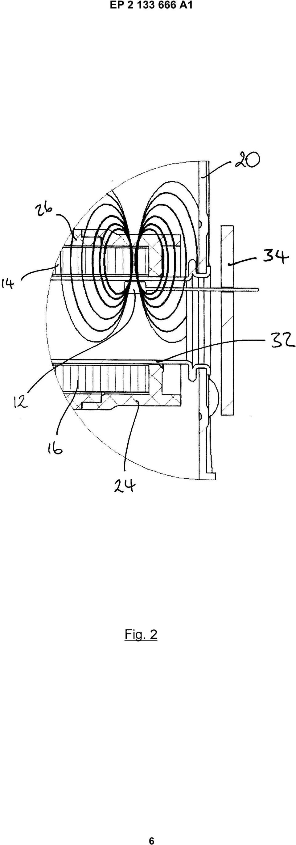
7 EP A1 7
8 EP A1 8
TEPZZ 87_546A T EP 2 871 546 A2 (19) (11) EP 2 871 546 A2 (12) EUROPEAN PATENT APPLICATION. (51) Int Cl.: G05B 19/05 (2006.01)
 (11) EP 2 871 546 A2 (12) EUROPEAN PATENT APPLICATION. (51) Int Cl.: G05B 19/05 (2006.01)") (19) TEPZZ 87_46A T (11) EP 2 871 46 A2 (12) EUROPEAN PATENT APPLICATION (43) Date of publication: 13.0.1 Bulletin 1/ (1) Int Cl.: G0B 19/0 (06.01) (21) Application number: 14188238.1 (22) Date of filing:
(19) TEPZZ 87_46A T (11) EP 2 871 46 A2 (12) EUROPEAN PATENT APPLICATION (43) Date of publication: 13.0.1 Bulletin 1/ (1) Int Cl.: G0B 19/0 (06.01) (21) Application number: 14188238.1 (22) Date of filing:
TEPZZ 9 Z5A_T EP 2 922 305 A1 (19) (11) EP 2 922 305 A1. (12) EUROPEAN PATENT APPLICATION published in accordance with Art.
 (11) EP 2 922 305 A1. (12) EUROPEAN PATENT APPLICATION published in accordance with Art.") (19) TEPZZ 9 ZA_T (11) EP 2 922 A1 (12) EUROPEAN PATENT APPLICATION published in accordance with Art. 13(4) EPC (43) Date of publication: 23.09.1 Bulletin 1/39 (21) Application number: 1386446.2 (22) Date
(19) TEPZZ 9 ZA_T (11) EP 2 922 A1 (12) EUROPEAN PATENT APPLICATION published in accordance with Art. 13(4) EPC (43) Date of publication: 23.09.1 Bulletin 1/39 (21) Application number: 1386446.2 (22) Date
*EP001520563A1* EP 1 520 563 A1 (19) (11) EP 1 520 563 A1 (12) EUROPEAN PATENT APPLICATION. (43) Date of publication: 06.04.2005 Bulletin 2005/14
 (11) EP 1 520 563 A1 (12) EUROPEAN PATENT APPLICATION. (43) Date of publication: 06.04.2005 Bulletin 2005/14") (19) Europäisches Patentamt European Patent Office Office européen des brevets *EP001520563A1* (11) EP 1 520 563 A1 (12) EUROPEAN PATENT APPLICATION (43) Date of publication: 06.04.2005 Bulletin 2005/14
(19) Europäisches Patentamt European Patent Office Office européen des brevets *EP001520563A1* (11) EP 1 520 563 A1 (12) EUROPEAN PATENT APPLICATION (43) Date of publication: 06.04.2005 Bulletin 2005/14
EP 2 455 926 A1 (19) (11) EP 2 455 926 A1 (12) EUROPEAN PATENT APPLICATION. (43) Date of publication: 23.05.2012 Bulletin 2012/21
 (11) EP 2 455 926 A1 (12) EUROPEAN PATENT APPLICATION. (43) Date of publication: 23.05.2012 Bulletin 2012/21") (19) (12) EUROPEAN PATENT APPLICATION (11) EP 2 4 926 A1 (43) Date of publication: 23.0.2012 Bulletin 2012/21 (21) Application number: 11190024.7 (1) Int Cl.: G08B 2/14 (2006.01) G08B 2/00 (2006.01) G0B
(19) (12) EUROPEAN PATENT APPLICATION (11) EP 2 4 926 A1 (43) Date of publication: 23.0.2012 Bulletin 2012/21 (21) Application number: 11190024.7 (1) Int Cl.: G08B 2/14 (2006.01) G08B 2/00 (2006.01) G0B
TEPZZ 6_Z76 A_T EP 2 610 763 A1 (19) (11) EP 2 610 763 A1 (12) EUROPEAN PATENT APPLICATION. (51) Int Cl.:
 (11) EP 2 610 763 A1 (12) EUROPEAN PATENT APPLICATION. (51) Int Cl.:") (19) TEPZZ 6_Z76 A_T (11) EP 2 6 763 A1 (12) EUROPEAN PATENT APPLICATION (43) Date of publication: 03.07.2013 Bulletin 2013/27 (51) Int Cl.: G06F 17/30 (2006.01) (21) Application number: 12192220.7 (22)
(19) TEPZZ 6_Z76 A_T (11) EP 2 6 763 A1 (12) EUROPEAN PATENT APPLICATION (43) Date of publication: 03.07.2013 Bulletin 2013/27 (51) Int Cl.: G06F 17/30 (2006.01) (21) Application number: 12192220.7 (22)
EP 2 492 881 A2 (19) (11) EP 2 492 881 A2 (12) EUROPEAN PATENT APPLICATION. (43) Date of publication: 29.08.2012 Bulletin 2012/35
 (11) EP 2 492 881 A2 (12) EUROPEAN PATENT APPLICATION. (43) Date of publication: 29.08.2012 Bulletin 2012/35") (19) (12) EUROPEAN PATENT APPLICATION (11) EP 2 492 881 A2 (43) Date of publication: 29.08.2012 Bulletin 2012/35 (51) Int Cl.: G08B 13/16 (2006.01) G08B 25/08 (2006.01) (21) Application number: 12386006.6
(19) (12) EUROPEAN PATENT APPLICATION (11) EP 2 492 881 A2 (43) Date of publication: 29.08.2012 Bulletin 2012/35 (51) Int Cl.: G08B 13/16 (2006.01) G08B 25/08 (2006.01) (21) Application number: 12386006.6
TEPZZ 84 587A_T EP 2 843 587 A1 (19) (11) EP 2 843 587 A1 (12) EUROPEAN PATENT APPLICATION. (51) Int Cl.: G06F 21/64 (2013.01)
 (11) EP 2 843 587 A1 (12) EUROPEAN PATENT APPLICATION. (51) Int Cl.: G06F 21/64 (2013.01)") (19) TEPZZ 84 87A_T (11) EP 2 843 87 A1 (12) EUROPEAN PATENT APPLICATION (43) Date of publication: 04.03.201 Bulletin 201/ (1) Int Cl.: G06F 21/64 (2013.01) (21) Application number: 13181902.1 (22) Date
(19) TEPZZ 84 87A_T (11) EP 2 843 87 A1 (12) EUROPEAN PATENT APPLICATION (43) Date of publication: 04.03.201 Bulletin 201/ (1) Int Cl.: G06F 21/64 (2013.01) (21) Application number: 13181902.1 (22) Date
TEPZZ 68575_A_T EP 2 685 751 A1 (19) (11) EP 2 685 751 A1. (12) EUROPEAN PATENT APPLICATION published in accordance with Art.
 (11) EP 2 685 751 A1. (12) EUROPEAN PATENT APPLICATION published in accordance with Art.") (19) TEPZZ 687_A_T (11) EP 2 68 71 A1 (12) EUROPEAN PATENT APPLICATION published in accordance with Art. 3(4) EPC (43) Date of publication:.01.14 Bulletin 14/03 (21) Application number: 1278849.6 (22)
(19) TEPZZ 687_A_T (11) EP 2 68 71 A1 (12) EUROPEAN PATENT APPLICATION published in accordance with Art. 3(4) EPC (43) Date of publication:.01.14 Bulletin 14/03 (21) Application number: 1278849.6 (22)
EP 2 365 669 A1 (19) (11) EP 2 365 669 A1 (12) EUROPEAN PATENT APPLICATION. (43) Date of publication: 14.09.2011 Bulletin 2011/37
 (11) EP 2 365 669 A1 (12) EUROPEAN PATENT APPLICATION. (43) Date of publication: 14.09.2011 Bulletin 2011/37") (19) (12) EUROPEAN PATENT APPLICATION (11) EP 2 36 669 A1 (43) Date of publication: 14.09.11 Bulletin 11/37 (1) Int Cl.: H04L 12/8 (06.01) (21) Application number: 00243.6 (22) Date of filing:.03. (84)
(19) (12) EUROPEAN PATENT APPLICATION (11) EP 2 36 669 A1 (43) Date of publication: 14.09.11 Bulletin 11/37 (1) Int Cl.: H04L 12/8 (06.01) (21) Application number: 00243.6 (22) Date of filing:.03. (84)
EP 2 354 708 A2 (19) (11) EP 2 354 708 A2 (12) EUROPEAN PATENT APPLICATION. (43) Date of publication: 10.08.2011 Bulletin 2011/32
 (11) EP 2 354 708 A2 (12) EUROPEAN PATENT APPLICATION. (43) Date of publication: 10.08.2011 Bulletin 2011/32") (19) (12) EUROPEAN PATENT APPLICATION (11) EP 2 354 708 A2 (43) Date of publication:.08.2011 Bulletin 2011/32 (51) Int Cl.: F24H 3/08 (2006.01) F24H 8/00 (2006.01) (21) Application number: 111536.8 (22)
(19) (12) EUROPEAN PATENT APPLICATION (11) EP 2 354 708 A2 (43) Date of publication:.08.2011 Bulletin 2011/32 (51) Int Cl.: F24H 3/08 (2006.01) F24H 8/00 (2006.01) (21) Application number: 111536.8 (22)
TEPZZ 8898 7A_T EP 2 889 827 A1 (19) (11) EP 2 889 827 A1 (12) EUROPEAN PATENT APPLICATION. (51) Int Cl.: G06Q 40/04 (2012.01)
 (11) EP 2 889 827 A1 (12) EUROPEAN PATENT APPLICATION. (51) Int Cl.: G06Q 40/04 (2012.01)") (19) TEPZZ 8898 7A_T (11) EP 2 889 827 A1 (12) EUROPEAN PATENT APPLICATION (43) Date of publication: 01.07.201 Bulletin 201/27 (1) Int Cl.: G06Q 40/04 (2012.01) (21) Application number: 14199864.1 (22)
(19) TEPZZ 8898 7A_T (11) EP 2 889 827 A1 (12) EUROPEAN PATENT APPLICATION (43) Date of publication: 01.07.201 Bulletin 201/27 (1) Int Cl.: G06Q 40/04 (2012.01) (21) Application number: 14199864.1 (22)
TEPZZ 69 49A_T EP 2 693 349 A1 (19) (11) EP 2 693 349 A1 (12) EUROPEAN PATENT APPLICATION. (51) Int Cl.: G06F 17/30 (2006.01)
 (11) EP 2 693 349 A1 (12) EUROPEAN PATENT APPLICATION. (51) Int Cl.: G06F 17/30 (2006.01)") (19) TEPZZ 69 49A_T (11) EP 2 693 349 A1 (12) EUROPEAN PATENT APPLICATION (43) Date of publication: 0.02.2014 Bulletin 2014/06 (1) Int Cl.: G06F 17/30 (2006.01) (21) Application number: 13160696.4 (22)
(19) TEPZZ 69 49A_T (11) EP 2 693 349 A1 (12) EUROPEAN PATENT APPLICATION (43) Date of publication: 0.02.2014 Bulletin 2014/06 (1) Int Cl.: G06F 17/30 (2006.01) (21) Application number: 13160696.4 (22)
TEPZZ 65Z79 A_T EP 2 650 793 A1 (19) (11) EP 2 650 793 A1. (12) EUROPEAN PATENT APPLICATION published in accordance with Art.
 (11) EP 2 650 793 A1. (12) EUROPEAN PATENT APPLICATION published in accordance with Art.") (19) TEPZZ 65Z79 A_T (11) EP 2 650 793 A1 (12) EUROPEAN PATENT APPLICATION published in accordance with Art. 153(4) EPC (43) Date of publication: 16.10.2013 Bulletin 2013/42 (21) Application number: 12818771.3
(19) TEPZZ 65Z79 A_T (11) EP 2 650 793 A1 (12) EUROPEAN PATENT APPLICATION published in accordance with Art. 153(4) EPC (43) Date of publication: 16.10.2013 Bulletin 2013/42 (21) Application number: 12818771.3
TEPZZ 9 _88_A_T EP 2 921 881 A1 (19) (11) EP 2 921 881 A1 (12) EUROPEAN PATENT APPLICATION
 (11) EP 2 921 881 A1 (12) EUROPEAN PATENT APPLICATION") (19) TEPZZ 9 _88_A_T (11) EP 2 921 881 A1 (12) EUROPEAN PATENT APPLICATION (43) Date of publication: 23.09.1 Bulletin 1/39 (21) Application number: 1416041.2 (1) Int Cl.: G01T 1/ (06.01) G03B 42/02 (06.01)
(19) TEPZZ 9 _88_A_T (11) EP 2 921 881 A1 (12) EUROPEAN PATENT APPLICATION (43) Date of publication: 23.09.1 Bulletin 1/39 (21) Application number: 1416041.2 (1) Int Cl.: G01T 1/ (06.01) G03B 42/02 (06.01)
TEPZZ 87657ZA_T EP 2 876 570 A1 (19) (11) EP 2 876 570 A1 (12) EUROPEAN PATENT APPLICATION
 (11) EP 2 876 570 A1 (12) EUROPEAN PATENT APPLICATION") (19) TEPZZ 8767ZA_T (11) EP 2 876 70 A1 (12) EUROPEAN PATENT APPLICATION (43) Date of publication: 27.0.201 Bulletin 201/22 (21) Application number: 14189809.8 (1) Int Cl.: G06F 21/34 (2013.01) G08B 13/196
(19) TEPZZ 8767ZA_T (11) EP 2 876 70 A1 (12) EUROPEAN PATENT APPLICATION (43) Date of publication: 27.0.201 Bulletin 201/22 (21) Application number: 14189809.8 (1) Int Cl.: G06F 21/34 (2013.01) G08B 13/196
Title (fr) SOURCE IONIQUE INTERNE DOUBLE POUR PRODUCTION DE FAISCEAU DE PARTICULES AVEC UN CYCLOTRON
 SOURCE IONIQUE INTERNE DOUBLE POUR PRODUCTION DE FAISCEAU DE PARTICULES AVEC UN CYCLOTRON") Title (en) A TWIN INTERNAL ION SOURCE FOR PARTICLE BEAM PRODUCTION WITH A CYCLOTRON Title (de) DOPPELTE INTERNE IONENQUELLE FÜR PARTIKELSTRAHLHERSTELLUNG MIT EINEM ZYKLOTRON Title (fr) SOURCE IONIQUE INTERNE
Title (en) A TWIN INTERNAL ION SOURCE FOR PARTICLE BEAM PRODUCTION WITH A CYCLOTRON Title (de) DOPPELTE INTERNE IONENQUELLE FÜR PARTIKELSTRAHLHERSTELLUNG MIT EINEM ZYKLOTRON Title (fr) SOURCE IONIQUE INTERNE
TEPZZ 69 _ZA T EP 2 692 310 A2 (19) (11) EP 2 692 310 A2. (12) EUROPEAN PATENT APPLICATION published in accordance with Art.
 (11) EP 2 692 310 A2. (12) EUROPEAN PATENT APPLICATION published in accordance with Art.") (19) TEPZZ 69 _ZA T (11) EP 2 692 3 A2 (12) EUROPEAN PATENT APPLICATION published in accordance with Art. 13(4) EPC (43) Date of publication: 0.02.14 Bulletin 14/06 (21) Application number: 1276632.0 (22)
(19) TEPZZ 69 _ZA T (11) EP 2 692 3 A2 (12) EUROPEAN PATENT APPLICATION published in accordance with Art. 13(4) EPC (43) Date of publication: 0.02.14 Bulletin 14/06 (21) Application number: 1276632.0 (22)
EP 1 675 420 A1 (19) (11) EP 1 675 420 A1 (12) EUROPEAN PATENT APPLICATION. (43) Date of publication: 28.06.2006 Bulletin 2006/26
 (11) EP 1 675 420 A1 (12) EUROPEAN PATENT APPLICATION. (43) Date of publication: 28.06.2006 Bulletin 2006/26") (19) Europäisches Patentamt European Patent Office Office européen des brevets (12) EUROPEAN PATENT APPLICATION (11) EP 1 67 4 A1 (43) Date of publication: 28.06.06 Bulletin 06/26 (1) Int Cl.: H04Q 7/34
(19) Europäisches Patentamt European Patent Office Office européen des brevets (12) EUROPEAN PATENT APPLICATION (11) EP 1 67 4 A1 (43) Date of publication: 28.06.06 Bulletin 06/26 (1) Int Cl.: H04Q 7/34
Our patent and trade mark attorneys are here to help you protect and profit from your ideas, making sure they re working every bit as hard as you do.
 Our patent and trade mark attorneys are here to help you protect and profit from your ideas, making sure they re working every bit as hard as you do. Our people work with everyone from multi-nationals
TEPZZ 94Z968A_T EP 2 940 968 A1 (19) (11) EP 2 940 968 A1 (12) EUROPEAN PATENT APPLICATION. (51) Int Cl.: H04L 29/08 (2006.01)
 (11) EP 2 940 968 A1 (12) EUROPEAN PATENT APPLICATION. (51) Int Cl.: H04L 29/08 (2006.01)") (19) TEPZZ 94Z968A_T (11) EP 2 940 968 A1 (12) EUROPEAN PATENT APPLICATION (43) Date of publication: 04.11.20 Bulletin 20/4 (1) Int Cl.: H04L 29/08 (2006.01) (21) Application number: 1430649.7 (22) Date
(19) TEPZZ 94Z968A_T (11) EP 2 940 968 A1 (12) EUROPEAN PATENT APPLICATION (43) Date of publication: 04.11.20 Bulletin 20/4 (1) Int Cl.: H04L 29/08 (2006.01) (21) Application number: 1430649.7 (22) Date
TEPZZ 96 A_T EP 2 961 111 A1 (19) (11) EP 2 961 111 A1. (12) EUROPEAN PATENT APPLICATION published in accordance with Art.
 (11) EP 2 961 111 A1. (12) EUROPEAN PATENT APPLICATION published in accordance with Art.") (19) TEPZZ 96 A_T (11) EP 2 961 111 A1 (12) EUROPEAN PATENT APPLICATION published in accordance with Art. 13(4) EPC (43) Date of publication:.12.1 Bulletin 1/3 (21) Application number: 147426.7 (22) Date
(19) TEPZZ 96 A_T (11) EP 2 961 111 A1 (12) EUROPEAN PATENT APPLICATION published in accordance with Art. 13(4) EPC (43) Date of publication:.12.1 Bulletin 1/3 (21) Application number: 147426.7 (22) Date
 HU CZ FI PL SI PT IT ES NO NL FR DK SE IE GB AT DE CH LU 0 10 20 30 40 Foreigners' share Source: Eurostat More trust 3 4 5 6 7 PL HU CZ SI PT GR ES DK FI SE
Doro PhoneEasy 331ph
 Doro PhoneEasy 331ph 1 2 6 3 4 5 English 1 Ringer indicator 2 Hanging Hook for Handset 3 Redial function 4 Volume control 5 Flash button/programming 6 Speed dial memories This device is intended for the
EP 2 366 418 A2 (19) (11) EP 2 366 418 A2 (12) EUROPEAN PATENT APPLICATION. (43) Date of publication: 21.09.2011 Bulletin 2011/38
 (11) EP 2 366 418 A2 (12) EUROPEAN PATENT APPLICATION. (43) Date of publication: 21.09.2011 Bulletin 2011/38") (19) (12) EUROPEAN PATENT APPLICATION (11) EP 2 366 418 A2 (43) Date of publication: 21.09.2011 Bulletin 2011/38 (21) Application number: 11158108.8 (51) Int Cl.: A61M 5/36 (2006.01) A61M 5/315 (2006.01)
(19) (12) EUROPEAN PATENT APPLICATION (11) EP 2 366 418 A2 (43) Date of publication: 21.09.2011 Bulletin 2011/38 (21) Application number: 11158108.8 (51) Int Cl.: A61M 5/36 (2006.01) A61M 5/315 (2006.01)
TEPZZ 8 8 A_T EP 2 811 282 A1 (19) (11) EP 2 811 282 A1 (12) EUROPEAN PATENT APPLICATION. (51) Int Cl.: G01N 3/04 (2006.01) G01N 3/08 (2006.
 (11) EP 2 811 282 A1 (12) EUROPEAN PATENT APPLICATION. (51) Int Cl.: G01N 3/04 (2006.01) G01N 3/08 (2006.") (19) TEPZZ 8 8 A_T (11) EP 2 811 282 A1 (12) EUROPEAN PATENT APPLICATION (43) Date of publication:.12.14 Bulletin 14/0 (1) Int Cl.: G01N 3/04 (06.01) G01N 3/08 (06.01) (21) Application number: 14170412.2
(19) TEPZZ 8 8 A_T (11) EP 2 811 282 A1 (12) EUROPEAN PATENT APPLICATION (43) Date of publication:.12.14 Bulletin 14/0 (1) Int Cl.: G01N 3/04 (06.01) G01N 3/08 (06.01) (21) Application number: 14170412.2
TEPZZ 799965A_T EP 2 799 965 A1 (19) (11) EP 2 799 965 A1. (12) EUROPEAN PATENT APPLICATION published in accordance with Art.
 (11) EP 2 799 965 A1. (12) EUROPEAN PATENT APPLICATION published in accordance with Art.") (19) TEPZZ 79996A_T (11) EP 2 799 96 A1 (12) EUROPEAN PATENT APPLICATION published in accordance with Art. 13(4) EPC (43) Date of publication: 0.11.14 Bulletin 14/4 (21) Application number: 14727698.4
(19) TEPZZ 79996A_T (11) EP 2 799 96 A1 (12) EUROPEAN PATENT APPLICATION published in accordance with Art. 13(4) EPC (43) Date of publication: 0.11.14 Bulletin 14/4 (21) Application number: 14727698.4
TEPZZ 79ZZ8_A_T EP 2 790 081 A1 (19) (11) EP 2 790 081 A1 (12) EUROPEAN PATENT APPLICATION. (43) Date of publication: 15.10.2014 Bulletin 2014/42
 (11) EP 2 790 081 A1 (12) EUROPEAN PATENT APPLICATION. (43) Date of publication: 15.10.2014 Bulletin 2014/42") (19) TEPZZ 79ZZ8_A_T (11) EP 2 790 081 A1 (12) EUROPEAN PATENT APPLICATION (43) Date of publication: 1..14 Bulletin 14/42 (1) Int Cl.: G0D 23/19 (06.01) (21) Application number: 1414221.7 (22) Date of
(19) TEPZZ 79ZZ8_A_T (11) EP 2 790 081 A1 (12) EUROPEAN PATENT APPLICATION (43) Date of publication: 1..14 Bulletin 14/42 (1) Int Cl.: G0D 23/19 (06.01) (21) Application number: 1414221.7 (22) Date of
(51) Int Cl.: H04L 12/58 (2006.01) H04L 29/06 (2006.01)
 Int Cl.: H04L 12/58 (2006.01) H04L 29/06 (2006.01)") (19) TEPZZ_986 8 B_T (11) EP 1 986 382 B1 (12) EUROPEAN PATENT SPECIFICATION (4) Date of publication and mention of the grant of the patent: 19.02.14 Bulletin 14/08 (1) Int Cl.: H04L 12/8 (06.01) H04L
(19) TEPZZ_986 8 B_T (11) EP 1 986 382 B1 (12) EUROPEAN PATENT SPECIFICATION (4) Date of publication and mention of the grant of the patent: 19.02.14 Bulletin 14/08 (1) Int Cl.: H04L 12/8 (06.01) H04L
ERMInE Database. Presentation by Nils Flatabø SINTEF Energy Research. ERMInE Workshop 2 - Northern Europe Oslo, 1. November 2006
 ERMInE Database Presentation by Nils Flatabø SINTEF Energy Research ERMInE Workshop 2 - Northern Europe Oslo, 1. November 26 Overview Content of the Ermine Database Electronic Questionnaire RTD&D Data
(51) Int Cl.: H04N 7/52 (2011.01)
 Int Cl.: H04N 7/52 (2011.01)") (19) TEPZZ_9776 B_T (11) EP 1 977 611 B1 (12) EUROPEAN PATENT SPECIFICATION (4) Date of publication and mention of the grant of the patent: 16.01.13 Bulletin 13/03 (21) Application number: 0683819.1 (22)
(19) TEPZZ_9776 B_T (11) EP 1 977 611 B1 (12) EUROPEAN PATENT SPECIFICATION (4) Date of publication and mention of the grant of the patent: 16.01.13 Bulletin 13/03 (21) Application number: 0683819.1 (22)
TEPZZ 88_898A_T EP 2 881 898 A1 (19) (11) EP 2 881 898 A1 (12) EUROPEAN PATENT APPLICATION. (51) Int Cl.: G06N 5/04 (2006.01) G06F 17/30 (2006.
 (11) EP 2 881 898 A1 (12) EUROPEAN PATENT APPLICATION. (51) Int Cl.: G06N 5/04 (2006.01) G06F 17/30 (2006.") (19) TEPZZ 88_898A_T (11) EP 2 881 898 A1 (12) EUROPEAN PATENT APPLICATION (43) Date of publication:.06. Bulletin /24 (1) Int Cl.: G06N /04 (06.01) G06F 17/ (06.01) (21) Application number: 136680.3 (22)
(19) TEPZZ 88_898A_T (11) EP 2 881 898 A1 (12) EUROPEAN PATENT APPLICATION (43) Date of publication:.06. Bulletin /24 (1) Int Cl.: G06N /04 (06.01) G06F 17/ (06.01) (21) Application number: 136680.3 (22)
egovernment Digital Agenda Scoreboard 2014
 egovernment Digital Agenda Scoreboard 2014 1 egovernment use in EU28 has been flat In 2013 egovernment services have been used by 41% of the EU28 population, down from 44% in 2012 and almost at the same
The EU Energy Tax Directive: overview about the proposed reform, impacts on national measures and state of play
 Environmentally Related Taxes and Fiscal Reform Rome, Thursday, 15 December 2011 The EU Energy Tax Directive: overview about the proposed reform, impacts on national measures and state of play A short
The EU s 2030 Effort Sharing Agreement
 The EU s 2030 Effort Sharing Agreement Brussels CEPS Workshop, 29.06.2015 Oliver Sartor, oliver.sartor@iddri.org Research Fellow, Climate & Energy Policy, IDDRI Celine MARCY, IDDRI Institute for Sustainable
*EP001139245A1* EP 1 139 245 A1 (19) (11) EP 1 139 245 A1 (12) EUROPEAN PATENT APPLICATION. (43) Date of publication: 04.10.2001 Bulletin 2001/40
 (11) EP 1 139 245 A1 (12) EUROPEAN PATENT APPLICATION. (43) Date of publication: 04.10.2001 Bulletin 2001/40") (19) Europäisches Patentamt European Patent Office Office européen des brevets *EP00113924A1* (11) EP 1 139 24 A1 (12) EUROPEAN PATENT APPLICATION (43) Date of publication: 04..01 Bulletin 01/ (1) Int
(19) Europäisches Patentamt European Patent Office Office européen des brevets *EP00113924A1* (11) EP 1 139 24 A1 (12) EUROPEAN PATENT APPLICATION (43) Date of publication: 04..01 Bulletin 01/ (1) Int
EUROPEAN PATENT APPLICATION. Hudson, NC 28638 (US) Chancery Lane London WC2A 1QU (GB)
 Chancery Lane London WC2A 1QU (GB)") (19) (12) Europaisches Patentamt European Patent Office Office europeen een des brevets EUROPEAN PATENT APPLICATION EP 0 889 344 A1 (43) Date of publication: (51) nt CI.6: G 02 B 6/44 07.01.1999 Bulletin
(19) (12) Europaisches Patentamt European Patent Office Office europeen een des brevets EUROPEAN PATENT APPLICATION EP 0 889 344 A1 (43) Date of publication: (51) nt CI.6: G 02 B 6/44 07.01.1999 Bulletin
TEPZZ 9 8Z87A_T EP 2 938 087 A1 (19) (11) EP 2 938 087 A1 (12) EUROPEAN PATENT APPLICATION
 (11) EP 2 938 087 A1 (12) EUROPEAN PATENT APPLICATION") (19) TEPZZ 9 8Z87A_T (11) EP 2 938 087 A1 (12) EUROPEAN PATENT APPLICATION (43) Date of publication: 28..1 Bulletin 1/44 (21) Application number: 14604.2 (1) Int Cl.: H04N 21/23 (11.01) H04N 21/488 (11.01)
(19) TEPZZ 9 8Z87A_T (11) EP 2 938 087 A1 (12) EUROPEAN PATENT APPLICATION (43) Date of publication: 28..1 Bulletin 1/44 (21) Application number: 14604.2 (1) Int Cl.: H04N 21/23 (11.01) H04N 21/488 (11.01)
MM, EFES EN. Marc Mathieu
 MM, EFES EN Marc Mathieu La Tribune Hewitt EUROPEAN EMPLOYEE OWNERSHIP ACROSS THE CRISIS Numbers 2006/2007/2008/2009 2009 2008 2007 2006 Employee owners 9.3 million 9.0 million 8.4 million Employees' share
ZTE Blade V Quick Start Guide
 ZTE Blade V Quick Start Guide LEGAL INFORMATION Copyright 2013 ZTE CORPORATION. All rights reserved. No part of this publication may be quoted, reproduced, translated or used in any form or by any means,
(51) Int Cl.: G06F 9/455 (2006.01) G06F 9/50 (2006.01)
 Int Cl.: G06F 9/455 (2006.01) G06F 9/50 (2006.01)") (19) TEPZZ 6987 B_T (11) EP 2 698 711 B1 (12) EUROPEAN PATENT SPECIFICATION (4) Date of publication and mention of the grant of the patent: 0.08.1 Bulletin 1/32 (21) Application number: 118777.8 (22) Date
(19) TEPZZ 6987 B_T (11) EP 2 698 711 B1 (12) EUROPEAN PATENT SPECIFICATION (4) Date of publication and mention of the grant of the patent: 0.08.1 Bulletin 1/32 (21) Application number: 118777.8 (22) Date
European Research Council
 ERC Starting Grant Outcome: Indicative statistics Reproduction is authorised provided the source ERC is acknowledged ERCEA/JH. ERC Starting Grant: call Submitted and selected proposals by domain Submitted
European Research Council
 ERC Advanced Grants 2011 Outcome: Indicative Statistics Reproduction is authorised provided that the source ERC is acknowledged NB: In these graphs grantee refers to a candidate selected for ERC funding
SME Instrument statistics
 SME Instrument statistics 0 beneficiaries Phase (June Sep 0), Phase (Oct 0) status January 0 SME Instrument (Horizon 00) DCC MANAGEMENT 0 SME Instrument Phase (Jun 0) beneficiaries Country breakdown Out
sparktable: Generating Graphical Tables for Websites and Documents with R
 Alexander Kowarik 1, Bernhard Meindl 1 and Matthias Templ 1,2 1. Statistics Austria 2. Vienna University of Technology Q Vienna, June, 2014 sparktable: Generating Graphical Tables for Websites and Documents
(12) Oversettelse av europeisk patentskrift
 Oversettelse av europeisk patentskrift") (12) Oversettelse av europeisk patentskrift (11) NO/EP 2294743 B1 (19) NO NORGE (51) Int Cl. H04L 1/16 (2006.01) H04L 1/18 (2006.01) Patentstyret (21) Oversettelse publisert 2012.12.10 (80) Dato for Den
(12) Oversettelse av europeisk patentskrift (11) NO/EP 2294743 B1 (19) NO NORGE (51) Int Cl. H04L 1/16 (2006.01) H04L 1/18 (2006.01) Patentstyret (21) Oversettelse publisert 2012.12.10 (80) Dato for Den
OHIM SEARCH TOOLS: TMVIEW, DSVIEW AND TMCLASS. Making trade mark and design information readily available for users
 OHIM SEARCH TOOLS: TMVIEW, DSVIEW AND TMCLASS Making trade mark and design information readily available for users Mariano Riccheri Moscow, 24 September 2015 INTERNATIONAL COOPERATION AREA European Cooperation:
SURVEY ON THE TRAINING OF GENERAL CARE NURSES IN THE EUROPEAN UNION. The current minimum training requirements for general care nurses
 SURVEY ON THE TRAINING OF GENERAL CARE NURSES IN THE EUROPEAN UNION This survey serves as a background document for the discussion of the Commission's legislative proposal to modernize the minimum requirements
Czech Universities and the Environment for Innovation. Rudolf Hanka
 Czech Universities and the Environment for Innovation Rudolf Hanka Czech Republic a cauldron of Central Europe? Geographical position Major motorways High speed backbone network Czech internet network
ENTERING THE EU BORDERS & VISAS THE SCHENGEN AREA OF FREE MOVEMENT. EU Schengen States. Non-Schengen EU States. Non-EU Schengen States.
 ENTERING THE EU BORDERS & VISAS THE SCHENGEN AREA OF FREE MOVEMENT An area without internal borders where EU citizens and non-eu nationals may move freely EU Schengen States Non-Schengen EU States IS Azores
Online job search in the EU: The potential of web 2.0
 Online job search in the EU: The potential of web 2.0 Professor Helen Margetts and Dr Rebecca Eynon Oxford Internet Institute (OII) http://www.egovbarriers.org Overview Current status of online job search
KNOWLEDGE ECONOMY CHALLENGES FOR LIFEONG LEARNING
 KNOWLEDGE ECONOMY CHALLENGES FOR LIFEONG LEARNING Anna Kaderabkova, Centre for Economic Studies, Prague www.cesvsem.cz 10. 11. 2006, Prague 1 Structure: 1. Innovation-driven demand for skills in enterprises
Dublin, March 2013. EPSO Network of Experts in the field of Personnel Selection 14th March 2013
 Dublin, March 2013 EPSO Network of Experts in the field of Personnel Selection 14th March 2013 On-going and upcoming competitions AD2012 by Citizenship AD2012 Citizenship %EU Population validated application
Your first EURES job. Progress Summary 2014Q4. March 2015
 Progress Summary 04Q4 March 05 This summary presents an overview of the implementation of Your first Eures job since the start date of activities in June 0 until the end of 04. It highlights in particular
European developments in VET Quality Assurance
 Sophie Weisswange DGVT meeting European developments in VET Quality Assurance Dublin 22-23 May 2013 EQAVET EQAVET list of indicators Underlying objectives: Better employability Better match between training
Level crossing signs from the view of road users in Europe. Tamás Déri Hungarian NSA
 Level crossing signs from the view of road users in Europe. Tamás Déri Hungarian NSA Due to the different approach on level crossing regulation in the European Union, we made a survey within the European
How To Study The Small Ruminant Population In The European Land Animals
 1 Joint Research Centre (JRC) Economic Analysis of Electronic Identification (EID) of Small Ruminants in Member States IPSC - Institute for the Protection and Security of the Citizen Ispra - Italy http://ipsc.jrc.ec.europa.eu/
EN 106 EN 4. THE MOBILE USE OF THE INTERNET BY INDIVIDUALS AND ENTERPRISES. 4.1. Introduction
 4. THE MOBILE USE OF THE INTERNET BY INDIVIDUALS AND ENTERPRISES 4.1. Introduction This chapter looks at mobile use of the internet by individuals and enterprises, benefiting from new data collected in
February 2015. Euro-PCT applications: Claim amendment and other issues
 February 2015 Euro-PCT applications: Claim amendment and other issues February 2015 Issues arising when PCT applications enter the regional phase in the EPO Recent years have seen numerous changes to the
GUIDANCE for Administration of the Sunset Clause
 GUIDANCE Edition number : 02 Edition date: 16/07/2010 Implementation date : 28/12/2007 CMDv Secretariat: 7 Westferry Circus, Canary Wharf, London, E14 4HB, UK CMDv/TEM/013-00 Tel. (44-20) 74 18 84 00 Fax.
Hotel Industry VAT in EU
 Hotel Industry VAT in EU Hotel VAT DK 25 LT 21 SK 20 HU 18 CZ 15 HR 13 25 LV 12 SE 12 AVR 10 ES 10 20 FR 10 IT 10 AT 10 FI 10 SI 10 15 BG 9 EE 9 IE 9 CY 9 10 RO 9 PL 8 DE 7 MT 7 5 EL 7 BE 6 NL 6 PT 6 LU
The Transition to Tendering Perspective from the Manufacturing Industry
 The Transition to Tendering Perspective from the Manufacturing Industry Johannes Schiel, VDMA Power Systems Berlin, 12.11.2015 Lessons from Denmark Agora Event 2: Towards a Renewable Future - Energy Scenarios,
The case for a European Social Union. From muddling through to a sense of common purpose. Frank Vandenbroucke EIB Institute Luxembourg, 5 March 2015
 The case for a European Social Union. From muddling through to a sense of common purpose. Frank Vandenbroucke EIB Institute Luxembourg, 5 March 2015 A European Social Union A Social Union would support
Milk Market Situation. Brussels, 27 August 2015
 Milk Market Situation Brussels, 27 August EU Productions EU Productions (Jan-Jun compared to Jan-Jun 214) +,8% + 1,2% + 3,2% +,2% +,7% - 2,% - 3,1% -,1% - 11,1%!!! Data from some Member States are confidential
ASUS Transformer Pad QSG TF300TG 3G Connection Manager
 E7210 QSG TF300TG 3G Connection Manager Installing SIM card 1. Use a straightened paper clip to press the SIM card tray eject button. 2. Remove the tray from the slot. Orient and place the SIM card on
RL HW / RL HW+ / RL HGW / RL HV / RL HVPW/RL HVPW-G
 Auto-Levelling Rotary Laser Level RL HW / RL HW+ / RL HGW / RL HV / RL HVPW/RL HVPW-G 77-496 / 77-429 / 77-439 / 77-497 / 77-427/ 77-441 Please read these instructions before operating the product Auto-Levelling
CO2 BASED MOTOR VEHICLE TAXES IN THE EU IN 2015
 CO2 BASED MOTOR VEHICLE TAXES IN THE EU IN 2015 COUNTRY AT (AUSTRIA) BE (BELGIUM) BG (BULGARIA) CO2/FUEL CONSUMPTION TAXES A fuel consumption tax (Normverbrauchsabgabe or NoVA) is levied upon the first
(51) Int Cl.: B29C 41/20 (2006.01) F21S 4/00 (2006.01) H05K 3/28 (2006.01)
 Int Cl.: B29C 41/20 (2006.01) F21S 4/00 (2006.01) H05K 3/28 (2006.01)") (19) TEPZZ 68698B_T (11) EP 2 68 698 B1 (12) EUROPEAN PATENT SPECIFICATION (4) Date of publication and mention of the grant of the patent: 18.11.201 Bulletin 201/47 (21) Application number: 11808612.3
(19) TEPZZ 68698B_T (11) EP 2 68 698 B1 (12) EUROPEAN PATENT SPECIFICATION (4) Date of publication and mention of the grant of the patent: 18.11.201 Bulletin 201/47 (21) Application number: 11808612.3
2015 Half Year Results Conference Call Presentation. 26 August 2015
 2015 Half Year Results Conference Call Presentation 26 August 2015 1 Today s Call Participants Dr Patrik De Haes - CEO Dominique Vanfleteren CFO 2 Agenda for the Call 2015 Highlights US update : objectives
EXCHANGE STUDIES PRACTICAL INFORMATION. Kadri Toom International Relations Office, Tallinn University of Technology kadri.toom@ttu.
 EXCHANGE STUDIES PRACTICAL INFORMATION Kadri Toom International Relations Office, Tallinn University of Technology kadri.toom@ttu.ee; Tel 620 3549 STEP 1: SELECTION By exchange committees in faculties
Social dumping and free movement: Overview of current issues from an economic point of view
 Social dumping and free movement: Overview of current issues from an economic point of view Prof. dr. Jozef Pacolet & Frederic De Wispelaere Design Charles & Ray Eames - Hang it all Vitra Statistics on
Understanding the Alternator
 http://www.autoshop101.com THIS AUTOMOTIVE SERIES ON ALTERNATORS HAS BEEN DEVELOPED BY KEVIN R. SULLIVAN PROFESSOR OF AUTOMOTIVE TECHNOLOGY AT SKYLINE COLLEGE SAN BRUNO, CALIFORNIA ALL RIGHTS RESERVED
I have asked for asylum in the EU which country will handle my claim?
 EN I have asked for asylum in the EU which country will handle my claim? A Information about the Dublin Regulation for applicants for international protection pursuant to article 4 of Regulation (EU) No
Common Communication on the Common Practice on the General Indications of the Nice Class Headings v1.1, 20 February 2014
 Common Communication on the Common Practice on the General Indications of the Nice Class Headings v1.1, 1 20 February 2014 On 19/06/2012 the Court delivered its ruling in Case C-307/10 "IP Translator",
The long term policy view: Shifting Wealth, Income Inequalities and Demography - The Ageing Report
 The long term policy view: Shifting Wealth, Income Inequalities and Demography - The Ageing Report Per Eckefeldt European Commission Directorate General for Economic and Financial Affairs XXV Villa Mondragone
Finnish foreign trade 2014 Figures and diagrams. 27.2.2015 FINNISH CUSTOMS Statistics 1
 Finnish foreign trade 214 Figures and diagrams 27.2.215 FINNISH CUSTOMS Statistics 1 IMPORTS, EXPORTS AND TRADE BALANCE 199-214 7 billion e 6 5 4 3 2 1-1 9 91 92 93 94 95 96 97 98 99 1 2 3 4 5 6 7 8 9
THE FUTURE OF TELEVISION IN EUROPE
 Information Analytics Expertise SEPTEMBER 2014 THE FUTURE OF TELEVISION IN EUROPE An assessment of the changing nature of television in Europe, and what is shaping the transformation Ben Keen: IHS Technology
OVERVIEW OF PURCHASE AND TAX INCENTIVES FOR ELECTRIC VEHICLES IN THE EU
 01.04.2014 OVERVIEW OF PURCHASE AND TAX INCENTIVES FOR ELECTRIC VEHICLES IN THE EU This table provides an overview of the incentives that are granted in the Member States of the European Union for the
Study on comparison tools and third-party verification schemes
 Justice and Consumers Study on comparison tools and third-party verification schemes ECCG 25/03/2015 Julien Brugerolle JUST E6 Introduction Study objectives Explore consumer behavioural patterns in the
Market data for Europe-wide location and sales planning
 Market data for Europe-wide location and sales planning MRS: European Geodemographics Conference, April 1, 2009 Simone Baecker-Neuchl: GfK GeoMarketing GmbH Nuremberg, Germany. Agenda 1 Market data for
Export of unemployment benefits
 Export of unemployment benefits PD U2 Questionnaire June 2014 Prof. dr. Jozef Pacolet & Frederic De Wispelaere HIVA KU Leuven Network Statistics FMSSFE This report has been prepared in the framework of
DHL Door-To-More UNLOCKING THE POTENTIAL OF DIRECT DISTRIBUTION
 DHL Door-To-More UNLOCKING THE POTENTIAL OF DIRECT DISTRIBUTION 2 DHL Door-To-More TM DHL Door-To-More 3 DHL DOOR-TO-MORE The seamless intercontinental door-to-door distribution solution that delivers
Private Sector Debt Dívida do Sector Privado. dossiers. Economic Outlook Conjuntura Económica. Conjuntura Económica.
 dossiers Economic Outlook Private Sector Debt Dívida do Sector Privado Last Update Última Actualização:12/08/2015 Portugal Economy Probe (PE Probe) Prepared by PE Probe Preparado por PE Probe Copyright
GDP per capita, consumption per capita and comparative price levels in Europe
 Economy and finance Author: Lars SVENNEBYE Statistics in focus 2008 GDP per capita, consumption per capita and comparative price levels in Europe Final results for 2005 and preliminary results for 2006
Digital Agenda Targets Progress report. Digital Agenda Scoreboard 2014
 Digital Agenda Targets Progress report Digital Agenda Scoreboard 2014 1 NGA coverage: Fast broadband technologies capable of providing at least 30 Mbps are available to 64%, up from 54% a year ago Among
The ICT workforce and e-leadership demand and supply (2014-2020)
") The ICT workforce and e-leadership demand and supply (2014-2020) Tobias Hüsing, Senior Research Consultant, empirica GmbH Marianne Kolding, Vice President IDC European e-skills 2014 Conference e-leadership
The ICT workforce and e-leadership demand and supply (2014-2020) Tobias Hüsing, Senior Research Consultant, empirica GmbH Marianne Kolding, Vice President IDC European e-skills 2014 Conference e-leadership
How close? An attempt at measuring the cultural distance between countries
 Gustavo De Santis gustavo.desantis@unifi.it Mauro Maltagliati mauro.maltagliati@unifi.it How close? Silvana Salvini silvana.salvini@unifi.it An attempt at measuring the cultural distance between countries
UNIT II Robots Drive Systems and End Effectors Part-A Questions
 UNIT II Robots Drive Systems and End Effectors Part-A Questions 1. Define End effector. End effector is a device that is attached to the end of the wrist arm to perform specific task. 2. Give some examples
*EP001173363B1* EP 1 173 363 B1 (19) (11) EP 1 173 363 B1 (12) EUROPEAN PATENT SPECIFICATION
 (11) EP 1 173 363 B1 (12) EUROPEAN PATENT SPECIFICATION") (19) Europäisches Patentamt European Patent Office Office européen des brevets *EP001173363B1* (11) EP 1 173 363 B1 (12) EUROPEAN PATENT SPECIFICATION (4) Date of publication and mention of the grant of
(19) Europäisches Patentamt European Patent Office Office européen des brevets *EP001173363B1* (11) EP 1 173 363 B1 (12) EUROPEAN PATENT SPECIFICATION (4) Date of publication and mention of the grant of
SESAR. Luftfahrttechnologie - Auftaktveranstaltung zum 7. EU-Forschungsrahmenprogramm Wien, 4 Dezember 2006
 Luftfahrttechnologie - Auftaktveranstaltung zum 7. EU-Forschungsrahmenprogramm Wien, 4 Dezember 2006 SESAR Christian Pusch EUROCONTROL Experimental Centre European page 1Organisation of 22 for the Safety
Provisions re Professional Services in Cariforum-EC EPA
 Provisions re Professional Services in Cariforum-EC EPA Ramesh Chaitoo Head, Services Trade Unit CRNM - www.crnm.org rchaitoo@crnm.org rnmsts@yahoo.ca Structure of Title II - Investment, Trade in Services
GÉANT for HEAnet clients
 GÉANT for HEAnet clients Guy Roberts GÉANT CTO Office HEAnet National Conference 12 th November 2015 Global R+E connectivity for Ireland HEAnet + GÉANT provide access for Irish R+E users to the world s
Client-IP EDNS Option Concerns
 Client-IP EDNS Option Concerns RIPE 67, Athens Florian Streibelt TU-Berlin, Germany - FG INET www.inet.tu-berlin.de October 16th 2013 Preliminary results, full results at IMC
NECOCAR. International CATIA Project
 NECOCAR International CATIA Project 2008 GOAL The goal of this project is to design an electrocar for the Japanese public. Cute Comfortable Modern Ecological ORGANIZATION Russe-Français CATIA V5 R18 Sharing
telephone television internet 3-play (i + t + tv) 2-play 2-play (i+t) (t+tv) 2-play (i+tv)
 2-play 2-play (i+t) (t+tv) 2-play (i+tv)") T r i p l e p l a y a s a s e p a r a t e m a r k e t? Z o l tá n Pá p a i 2 2 n d E u r o p e a n R e g i o n a l I T S C o n f e r e n c e B u d a p e s t, 1 8-2 1 S e p t e m b e r, 2 0 1 1 T h e p
T r i p l e p l a y a s a s e p a r a t e m a r k e t? Z o l tá n Pá p a i 2 2 n d E u r o p e a n R e g i o n a l I T S C o n f e r e n c e B u d a p e s t, 1 8-2 1 S e p t e m b e r, 2 0 1 1 T h e p
Looking for the future model for roaming
 BoR (14) 155 Looking for the future model for roaming J. Scott Marcus 0 Roaming Regulation in Europe Past, present, and future? Regulation of IMR since 2007 can be viewed as comprising three phases 2007
CL90i. 77-021 Please read these instructions before operating the product. 3 - Beam Self-Leveling Cross Line Laser
 3 - Beam Self-Leveling Cross Line Laser CL90i 77-01 Please read these instructions before operating the product Self-Leveling GB D F I E PT NL DK SE FIN NO PL GR CZ RU HU SK SI BG RO EE LV LT Contents
EUROPEAN PATENT SPECIFICATION. (51) IntCL: G06F 13/10< 200B 1 > G06F 13/42( 2 OO 601 > (56) References cited: WO-A-97/19402 US-A- 6 085 265
 IntCL: G06F 13/10< 200B 1 > G06F 13/42( 2 OO 601 > (56) References cited: WO-A-97/19402 US-A- 6 085 265") (19) J Europäisches Patentamt European Patent Office Office européen des brevets (H) EP 1246 071 B1 (12) EUROPEAN PATENT SPECIFICATION (45) Date of publication and mention of the grant of the patent: 10.05.2006
(19) J Europäisches Patentamt European Patent Office Office européen des brevets (H) EP 1246 071 B1 (12) EUROPEAN PATENT SPECIFICATION (45) Date of publication and mention of the grant of the patent: 10.05.2006
(51) Int Cl.: G06F 11/14 (2006.01)
 Int Cl.: G06F 11/14 (2006.01)") (19) (12) EUROPEAN PATENT SPECIFICATION (11) EP 1 08 414 B1 (4) Date of publication and mention of the grant of the patent: 04.03.09 Bulletin 09/ (1) Int Cl.: G06F 11/14 (06.01) (21) Application number:
(19) (12) EUROPEAN PATENT SPECIFICATION (11) EP 1 08 414 B1 (4) Date of publication and mention of the grant of the patent: 04.03.09 Bulletin 09/ (1) Int Cl.: G06F 11/14 (06.01) (21) Application number:
EP 2 922 249 A1 (19) (11) EP 2 922 249 A1 (12) EUROPEAN PATENT APPLICATION. (43) Date of publication: 23.09.2015 Bulletin 2015/39
 (11) EP 2 922 249 A1 (12) EUROPEAN PATENT APPLICATION. (43) Date of publication: 23.09.2015 Bulletin 2015/39") (19) TEPZZ 9 49A_T (11) EP 2 922 249 A1 (12) EUROPEAN PATENT APPLICATION (43) Date of publication: 23.09. Bulletin /39 (21) Application number: 16003.0 (1) Int Cl.: H04L 12/7 (13.01) H04L 12/717 (13.01)
(19) TEPZZ 9 49A_T (11) EP 2 922 249 A1 (12) EUROPEAN PATENT APPLICATION (43) Date of publication: 23.09. Bulletin /39 (21) Application number: 16003.0 (1) Int Cl.: H04L 12/7 (13.01) H04L 12/717 (13.01)
TL-PS310U Single USB 2.0 Port MFP and Storage Server
 Single USB 2.0 Port MFP and Storage Server REV3.0.0 1910010947 COPYRIGHT & TRADEMARKS Specifications are subject to change without notice. is a registered trademark of TP-LINK TECHNOLOGIES CO., LTD. Other