CM16a Amplifier Network Monitor HARDWARE MANUAL
|
|
|
- Erica Rogers
- 8 years ago
- Views:
Transcription
1 CM16a Amplifier Network Monitor HARDWARE MANUAL *TD * TD Rev. B

2 WARNING While QSC has endeavored to develop and produce the most dependable and robust network audio product for your use, due to the myriad of network situations and equipment that may be encountered in its implementation, QSC cannot be held responsible for network conflicts and associated consequences that may result. For this reason, QSC strongly recommends that the network used for implementation of QSControl products be completely separate from all other networks, data or otherwise. As such, should you elect to integrate QSControl products with your existing network system, all risks attendant to such integration of QSControl products with your existing network or network systems are assumed by you. While QSC strives to provide the highest quality technical solutions for networked audio products, in no event will QSC or its suppliers be held liable for any damages, consequential, incidental or otherwise, including any claims for lost profits and/or savings resulting from any attempted integration of QSControl products with your networking systems. No agent, employee or representative of QSC has any authority to alter or modify in any manner, the disclosures and recommendations set forth herein. Copyright 2001, QSC Audio Products, Inc. QSC is a registered trademark of QSC Audio Products, Inc., Costa Mesa, CA QSC and the QSC logo are registered with the U.S. Patent and Trademark Office HyperTerminal is the copyrighted property of Hilgraeve Inc., Monroe, MI Phoenix Contact is the trademark of Phoenix Contact, Inc., Middletown, PA Riacon is the trademark of RIA electronic, Inc., Eatontown, NJ On-Shore Technology is the trademark of On-Shore Technology, Inc., Tempe, AZ All other trandemarks are the property of their respective owners 2

3 TABLE OF CONTENTS: CM16a Amplifier Network Monitor Section 1: INTRODUCTION Overview...5 Physical Characteristics & Layout...6 List of Functions & Features...8 Block Diagram...9 Detailed Description of Functions...11 Network Description...14 Network Examples...15 Section 2: INSTALLATION Basics: Unpacking...17 What is Included...17 Location Considerations...17 Mounting the CM16a...17 Connecting: AC Power...18 Audio Inputs...19 Page Input...20 RLY/TRG Input...20 RLY Output...20 Monitor Chain In/Out BASE-T Input/Output...21 RS-232 Port...21 Amplifiers...21 Rear Panel Detailed Illustration & Hookup Example...22 Section 3: OPERATION General: LED Behavior...23 Amp Setup, Network Setup...24 Presets...25 BYPASS Switch Usage...26 Serial Port Interface...27 Telnet Access...30 Fuse Replacement...31 Section 4: SPECIFICATIONS...32 Section 5: ARCHITECT S & ENGINEER S SPECIFICATION...36 Section 6: APPENDIX Ethernet Cable & RS-232 Pinouts...37 DataPort Pinout and Phoenix -type Connector Part Numbers...38 Section 7: QSC INFORMATION How to Contact QSC Audio Products

4 Important Safety Information! Please review the following important safety information before operating the CM16a. Explanation of Graphical Symbols The lightning flash with arrowhead symbol, within an equilateral triangle, is intended to alert the user to the presence of uninsulated dangerous voltage within the product s enclosure that may be of sufficient magnitude to constitute a risk of electric shock to humans. The exclamation point within an equilateral triangle is intended to alert the users to the presence of important operating and maintenance (servicing) instructions in the literature accompanying the product. SAFEGUARDS Electrical energy can perform many useful functions. This unit has been engineered and manufactured to assure your personal safety. Improper use can result in potential electrical shock or fire hazards. In order not to defeat the safeguards, observe the following instructions for its installation, use and servicing. CAUTION RISK OF ELECTRIC SHOCK DO NOT OPEN CAUTION: To reduce the risk of electric shock, do not remove the cover. No user-serviceable parts inside. Refer servicing to qualified service personnel. WARNING: To prevent fire or electric shock, do not expose this equipment to rain or moisture. 1- Maximum operating ambient temperature is 50 C (122 F). 2- Never restrict airflow through the device fan or vents. Please insure that the air intake and exhaust vents are unobstructed. 3- When installing equipment into rack, distribute the units evenly. Otherwise, hazardous conditions could be created by an uneven weight distribution. 4- Connect the unit only to a properly rated supply circuit. The CM16a is suitable for connection to VAC, hertz, with no special considerations other than the appropriate IEC power cord. Federal Communications Commission (FCC) Information NOTE: This equipment has been tested and found to comply with the limits for a Class A digital device, pursuant to Part 15 of the FCC Rules. These limits are designed to provide reasonable protection against harmful interference in a commercial installation. This equipment generates, uses, and can radiate radio frequency energy and, if not installed and used in accordance with the instructions, may cause harmful interference to radio communications. Operation of this equipment in a residential area is likely to cause harmful interference, in which case the user will be required to correct the interference at his or her own expense. 5- Reliable Earthing (Grounding) of rack-mounted equipment should be maintained. 4
 instructions in the literature accompanying the")
5 Section 1: Introduction- Overview The QSC CM16a Amplifier Network Monitor provides powerful amplifier management and zone paging capability in a QSControl networked audio system using Ethernet networking technology to communicate with the host computer/ system controller. The host computer uses the QSControl application software to operate the networked audio system, including the CM16a s and their amplifiers. The software operates on the Microsoft Windows NT version 4.0 operating system and can be customized using Microsoft Visual Basic Professional Edition. This manual outlines the capabilities of the CM16a as well as its installation and connections. The operation of the CM16a is accomplished using QSC s QSControl software. Note that not all hardware features may be supported by the current software revision. Please refer to the software s documentation & help file for information regarding software features, usage and functions. Each CM16a performs control and monitoring functions for up to 16 amplifier channels. This could be up to eight 2-channel or four 4-channel amplifiers (or some combination of these) at the time this document was printed. The amplifiers supported by the CM16a are the PowerLight, PL2, PL2A, DCA, and CX series of QSC amplifiers that have a built-in Data Port. Models that do not have a built-in DataPort or models that have a DP- 1 option or V2 DataPort (such as the EX, MXa, & ISA series) are NOT supported by the CM16a. The DataPort connections are made with ordinary VGA computer monitor-type cables (HD-15 male-to-male). These cables are the same type that are used on personal computer systems to connect the monitor to the computer. This allows you to use commonly available cabling for interconnecting amplifiers to the CM16a. Each DataPort connection supports the control and monitoring functions for two audio channels. When using the CM16a with amplifiers that have more than two channels (such as the 4 channel cinema amplifiers) additional DataPort connections are required. The CM16a is a control and monitoring device that relies on software to do its job. The functions and capabilities provided in the design of the CM16a can only be realized with proper software implementation. Keep in mind that this manual s intent is to outline these capabilities and provide a reference for properly installing and interconnecting the CM16a to the networked system s host computer, the audio inputs and the amplifiers to be controlled and monitored. A thorough knowledge of the control software s features and operation will provide the best possible results for the end user. From all of us at QSC Audio Products, thank you for your purchase. Note: PL2A amplfiers have programmable filters and crossovers. This makes gain reporting to the host unreliable as the frequency content relates directly to reported output levels. Since the output level is used to calculate gain, it is not possible to gaurantee accurate gain reporting when the PL2A is set for any of its various frequency boost/ cut/crossover modes. 5

6 Section 1: Introduction- Physical Characteristics & Layout PHYSICAL CHARACTERISTICS The CM16a is one rack space high (1RU) and has an internal, univeral V AC power supply. The chassis is 37.7 cm (14.84 ) deep. The width of the chassis, less rack ears, is 43.7 cm (17.20 ). For detailed mounting dimensions, refer to the Section 4: Specifications- Dimensions (page 32). The weight of the CM16a is approximately 5 kilograms (11 pounds). FRONT PANEL (numbers correspond to reference locations shown in illustration above) 1- POWER switch 2- Cooling air exhaust vents (intake vents are located on left side of chassis as viewed from the front) 3- POWER on indicator 4- DIAGNOSTIC indicator 5- RCV, XMT and LINK STATUS network status indicators 6- PORT A - PORT H connection indicators 7- Access hole for the BYPASS switch (this is not labeled on the panel) 6
 1- POWER switch 2- Cooling air exhaust vents (intake vents are located on left side of chassis as viewed from the")
7 Section 1: Introduction- Physical Layout Diagram REAR PANEL (numbers correspond to reference locations shown above) 1- DataPort connectors PORT A - PORT H 2- PORT A CH 1 - PORT H CH 16 three-pin receptacles for audio inputs 3- PAGE three-pin receptacle for paging audio signal input 4- MONITOR CHAIN, IN and OUT five-pin receptacle for audio monitoring functions 5- RLY / TRG IN two-pin receptacle for remote sensing of switch closure or logic event 6- RLY OUT three-pin receptacle for output terminals of CM16a s internal SPDT relay contacts 7- RCV, XMT and LINK STATUS network status indicators 8-10BASE-T RJ-45 Ethernet computer network connection 9- RS-232 port for network and firmware utilities 10- IEC-type detachable AC power cord receptacle (for connection to AC line cord) with integral fuse holder 7
")
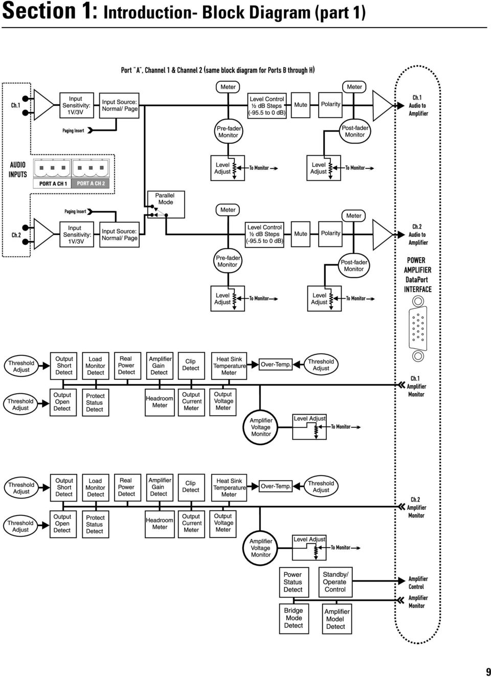
8 Section 1: Introduction- List of Functions & Features FUNCTIONAL LISTING, BLOCK DIAGRAM & DETAILED DESCRIPTIONS The CM16a performs remote control and monitoring of amplifiers. Below is a listing of the functions available for the supported QSC amplifiers. The following two pages (Block Diagram part 1 & 2) illustrate the main functions of the CM16a. Following the diagram is a section giving detailed explanations on each functional block that will aid in the use of the CM16a. Note that not all features may be supported by the current revision level of software (consult software documentation for supported feature set). Where applicable, functions are available on each individual audio channel. CONTROL FUNCTIONS Amplifier: Power (Standby/Operate Control) CM16a: Input Sensitivity Select Input Source Select (Normal/Page) Signal Level Control Signal Polarity Select Signal Mute Paging Control (with customizable routing) Contact Closure Output (switching of internal relay for control of external device) Paralleling within DataPort Pair MONITOR FUNCTIONS Amplifier: Power Status Amplifier Gain Amplifier Model Load Monitor (impedance) Output Voltage Output Power (real) Headroom Output Short Bridge Mode Protection Status Output Current Heat Sink Temperature (with Over-Temp.) Clipping Detect Output Open CM16a Input Level Meter Output Level Meter Audio Monitor Module (4 channel mono. mixer) External Event Sensing (a logic-level or switch input) SPECIAL FEATURES DAC (digital-to-analog converter) that can be used for generating test signals RS-232 Port for setting of network address information and system diagnostics 8 TFTP upgradeable firmware via Ethernet
.")
9 Section 1: Introduction- Block Diagram (part 1) 9
10 Section 1: Introduction- Block Diagram (part 2) 10

11 Section 1: Introduction- Detailed Description of Functions AUDIO FUNCTIONS Audio Inputs- These are the 3-pin terminal block connectors used for balanced line level audio-signal input. This type of connector is sometimes called Phoenix or Euro style. Input Sensitivity- Sets the sensitivity of the Audio Inputs to either 1 Volt or 3 Volts (r.m.s.). This selection should coincide with the level of the audio signal provided for each channel. Input Source: Normal/Page- Selects the input source for each channel. Normal input is the audio connected at the Audio Input terminals. Page input is the audio provided by the Paging Input Module. Level Control- Provides adjustment of the signal level delivered to the amplifier for each channel. Adjustment is from -95.5dB to 0dB in 0.5 db steps. Meter-These points are indicators of where in the audio path the software can meter the audio. Mute- Actively mutes the audio signal being passed by a channel. No signal is delivered to the amplifier when a channel is muted. Parallel Mode- When parallel mode is selected, the input to the first channel is also applied to the second channel. When in parallel mode, the input is ALWAYS from the first (or odd numbered) input. The second (or even numbered) input is ignored; this includes the PAGE signal. This feature is useful for sending one input signal to both amplifier channels without having to wire jumpers between the two input connectors. This mode is automatically enabled by the CM16a when the amplifier bridge mode is set to any of the parallel modes available (see amplifier manual for details). Polarity- Determines the polarity of the signal delivered to the amplifier for each channel. AUDIO MONITOR CHAIN FUNCTIONS Pre-Fader Monitor- Monitors the audio path at the point before the Level Control block (i.e. the input to the CM16a). Post-Fader Monitor- Monitors the audio path at the point after the Level Control, Mute, and Polarity blocks (i.e. the output from the CM16a). Amplifier Monitor- Monitors the audio at the output of the amplifier (i.e. the speaker terminals of the amplifier). Off- This selection disconnects the monitor for the channel. Level Adjust- Provides adjustment of the signal level delivered to the Monitor Module from each of the selectable tap points of a channel s audio path. Adjustment is from -95.5dB to 0dB in 0.5 db steps. Monitor Module- This module functions as a four-input mixer with software selection of the input channels. The four selected channels are summed with the external input, Monitor Chain In. For each of the inputs, the tap point is selectable from the pre-, post-, amplifier and off positions. AMPLIFIER CONTROL FUNCTIONS Standby/ Operate- Controls the amplifier s power status- ON- amplifier operational STANDBY- amplifier in standby mode NOTE! The amplifier must be powered in order to respond to any commands issued by the CM16a. This means the amp s power switch must physically be in the ON position. 11

12 Section 1: Introduction- Detailed Description of Functions AMPLIFIER MONITORING FUNCTIONS Amplifier Model Detect- Identifies what model of QSC amplifier is connected to the CM16a s DataPort. Amplifier Gain Detect- Reports the setting of the amplifier s gain setting (in db) for each channel. Bridge Mode Detect- Detects the position of the bridge mode switch on each amplifier. Clip Detect- Detects amplifier clipping on each channel. Headroom Metering- Reports the available remaining signal level that the input signal can be driven before clipping will occur. Heat Sink Temperature Metering- Monitors the heatsink temperature of each channel of each amplifier connected to the CM16a. If the temperature exceeds a user specified value (in software) then the Over-Temp. object will alert the system operator. Load Monitor Detect- Monitors the impedance of the load at the amplifier output for each channel. Output Current Meter- Provides for metering of the amplifier s output current on each channel. Output Voltage Meter- Provides for metering of the amplifier s output voltage on each channel. Output Open Detect- Detects when the load connected to the amplifier is above a user specified value in software. Protect Status Detect- Reports if the amplifier has entered protect mode (such as thermal, over-current or power-up muting protect status). Real Power Detect- Reports the real power the amplifier is delivering. This real power is not the same as reactive power. Real power is the product of current and voltage times the cosine of the phase angle between them. Threshold Adjust- This indicates that the behavior of the associated block requires the input of a threshold value in software that must be crossed for the detection to occur. This allows the system operator to tailor the behavior of the system to each application. PAGING FUNCTIONS Input Sensitivity- Sets the sensitivity of the Page Input to either 1 Vrms or 3 Vrms. This selection should coincide with the level of the audio signal provided for the Page Input. DAC- This is a digital-to-analog converter that takes digital information from the internal microcontroller and outputs the corresponding analog equivalent to the appropriate channel PAGE insert points. This occurs only by instructions issued by the system operator or a custom control application. Page Input- This is a 3-pin terminal block connector used for balanced line level page audio-signal input. Output Short Detect- Detects when the amplifier load is below a user specified value in software. Power Status Detect- Reports AC power status of the amplifier (ON/standby/ OFF). 12

13 Section 1: Introduction- Detailed Description of Functions RS-232 PORT FUNCTIONS RS-232 Port- The RS-232 (serial) port is used to communicate with the CM16a for Ethernet address setup and other diagnostic purposes. Most users will never have a need to access the RS232 port, but for customized networks and for troubleshooting system problems, it may be necessary. For the RS-232 port utilities, see the Operation section, Serial Port I/O Interface which outlines the proper connection and communication settings required to communicate with the CM16a via the serial (RS232) port. If the CM16a is connected to an Ethernet network where the factory-provided IP address information is not acceptable, the IP configuration may be changed using the RS-232 port. This involves connecting a computer with a properly configured serial port to the CM16a using a null-modem type cable (such as a Laplink cable) and running a dumb-terminal program (HyperTerminal is the Microsoft Windows- supplied program). DO NOT CHANGE THE FACTORY SETTINGS UNLESS YOU ARE CERTAIN OF WHAT YOU ARE DO- ING! If addressing is configured incorrectly, the CM16a may not respond to network control. CONTACT CLOSURE I/O FUNCTIONS RLY OUT- This is a 3-pin terminal block connector used for remotely controlling an electrical device in an on/off manner (such as a cooling fan, an audible alarm, a light, etc.). An internal SPDT (single-pole, double throw) relay is controlled by software command. Its contacts are accessible at the rear panel RLY OUT connector and are labeled: NC (normally closed) NO (normally open) C (common) RLY/TRG IN- Detects the closure (or opening) of a switch connected to the RLY/TRIG IN terminals on the rear panel. Also accepts CMOS and TTL logic-level inputs. An example is the detection of a limit-switch that indicates an open door on an equipment cabinet. This input may also be configured to activate (recall) certain presets without the need for a computer. Setup for this feature is possible using the Serial Port I/O or Telnet sessions outlined on pages (ref. menu item #10). Note- The factory-programmed IP address is printed on a label affixed to the front panel of the CM16a. Record this IP address in a safe place in case the label becomes lost. 13
 port. If the CM16a is connected to an Ethernet network where the factory-provided IP address information is not acceptable, the IP configuration may be changed using the RS-232 port.")
14 Section 1: Introduction- Network Description QSC CM16a Amplifier Network Monitors are designed to operate on standard 10BASE-T Ethernet. Each CM16a operates as a respective node on its network; each unit contains a programmable IP address in nonvolatile memory. To minimize network conflicts, each IP address should be unique. When shipped from the factory, the CM16a s factory-programmed IP address is printed on a label affixed to the front panel of the unit. Record the unit s IP address and serial number and keep in a safe place. Ethernet devices such as hubs, repeaters, switches and routers will usually afford the flexibility to configure the network as needed. The system controller computer on the network must have an Ethernet-compatible network interface card (NIC) installed. Additionally, if operation during power outage or interruption is required, an uninterruptable power supply (UPS) will be required for the host computer, CM16a, and any hubs, switches or repeaters. If the CM16a is disconnected from the network for any reason, it will continue to process audio using the last settings, assuming AC power is uninterrupted. The CM16a connects to the network via its RJ-45 connector on the rear panel. This allows direct connection to a 10BASE-T network. Use Category 3 (or better) unshielded twisted pair (UTP) Ethernet Cable. Most ready-made Ethernet patch cables available today are rated at least Category 5 making them suitable for this application. One side note regarding Ethernet cabling: Although Category 3 data cable is called out as the minimum requirement, it is increasingly difficult to find. Higher grades of cable are becoming the normal stock with the proliferation of 100BASE-T Ethernet. Category 5 Ethernet cable is the most widely available type of data cabling as of this writing. So what does this mean? Use Category 3 if it is available and cost effective. If the cost of Category 5 cable is not prohibitive, it may be desirable to do your cabling runs with Category 5 due to its increased data rate capabilities. The extra capability may be needed for future system expansion where 100 BASE-T devices are used. 10BASE-T capability is all that is required for the CM16a and thus the call out for Category 3 as the minimum. 14

15 Section 1: Introduction- Sample Network Topologies The simplest network configuration is a single system controller computer and a CM16a connected by a single Ethernet crossover cable. A standard Ethernet cable would NOT work. The crossover-type cable must be used when connecting the CM16a directly to the system controller computer. This type of cable switches (or crosses over) the transmit and receive signals from one end to the other enabling connection without any intermediate devices. See page 37 for crossover cable pinouts. For CAT-3 or CAT-5 distances longer than 100 meters (~300 feet) a repeater must be used. An active hub or Ethernet switch may be used as well. Active hubs clean up and retransmit the network traffic, much as a repeater does, only with multiple ports. The active hub or switch would allow for future expansion. If there are two or more CM16a s in the network (or other network devices present) use a hub or switch to create a star topology. 15
 a repeater must be used. An active hub or Ethernet switch may be used as well.")
16 Section 1: Introduction- Sample Network Topologies Some networks have multiple system controller computers. This configuration is essentially the same as the second example with the addition of the second computer attached to the hub or switch. To create the more complex distributed star topologies needed for larger systems, use additional hubs or switches. Some have special uplink ports for connecting to other hubs or switches via a standard Ethernet cable. If the hubs or switches do not have uplink ports, then the hub-to-hub or switch-toswitch connection should use a crossovertype Ethernet cable. 16

17 Section 2: Installation- Basics and Mounting UNPACKING There are no special unpacking precautions for the CM16a. Keep the original packing material for reuse in the rare event that service be required on the CM16a. If service is required and the original packing material is not available, adequately protect for shipment (strong box of appropriate size, sufficient packing material to prevent impact damage or load shifting). WHAT IS INCLUDED IN THE CARTON 1- CM16a Amplifier Network Monitor 2- AC Power Cord 3- One complete set of the Phoenix -type connectors (18 pcs. of 3-pin style, 1 pc. of 5-pin style & 1 pc. of 2-pin style) 4- Hardware manual (this document) LOCATION CONSIDERATIONS Where the CM16a is installed is dependent upon the location of audio input sources, amplifiers and network access. The system controller computer should be located someplace convenient for the system operator. In most instances, the system controller computer is remote from the CM16a and the amplifiers. It is preferable to install the CM16a and the amplifiers in the same or adjacent equipment racks; this allows the cabling between them to be standard 15 pin VGA monitor cables. These cables are generally 2 meters long (6.5 feet). For longer cabling runs, contact QSC s Technical Services Department at (800) (toll free U.S.A. only) or (714) QSC offers a special cable with individually-shielded twisted-pairs for each audio path; this cable can be used over distances as long as 100 meters (328 feet). The maximum length of any 10BASE-T Ethernet network segment (cabling between any node and the next node, hub or repeater) is 100 meters (328 feet). The location of hubs and repeaters must be such that this distance limit is not exceeded. If this is impractical or impossible, then use appropriate network transceivers and fiber optic cabling. For larger Ethernet networks, the use of Ethernet routers may be necessary. MOUNTING THE CM16a Note- Rack mounting is optional. The CM16a is secured to the front of the equipment rack with four screws and washers. Be sure to support the weight of the CM16a when securing to avoid distorting or bending the front panel mounting ears. For mobile, touring or portable applications, support the rear of the CM16a using the rear mounting tabs provided or contact QSC s Technical Services Department to order rear rack ear extensions. The rear rack ear extension kits add flexibility to you installation options as well as a support-pin option that requires one-time hardware installation at the rear of the rack. For the locating dimensions of the rear support mounting tabs, see the dimensional diagram in the specification section. 17
. WHAT IS INCLUDED IN THE CARTON 1- CM16a Amplifier Network Monitor 2- AC Power Cord 3- One complete set of the Phoenix -type connectors (18 pcs. of 3-pin style, 1 pc.")
18 Section 2: Installation- Mounting and AC Power MOUNTING THE CM16a (continued): The illustration below, left, shows the basic mounting technique. Support the CM16a from underneath while positioning the mounting holes in the desired location in the rack. Secure with standard rack hardware. The CM16a uses fan-drawn air for cooling. The air intake is on the left side of the chassis and the exhaust vents are on the front panel. Be certain not to obstruct these openings! Allow ample open space around them in order to maintain unobstructed air flow. Note! The CM16a s recommended ambient operating temperature is 0 C. to 50 C. (32 F. to 122 F.). Do not install the CM16a in environments that expose it to temperatures outside this range. Some equipment rack environments can get hot. If there is any question, measure the air temperature inside the equipment rack and supply additional cooling (air flow) to keep the ambient temperature within the specified limits. QSC amplifiers use back-to-front air flow and therefore do not exhaust hot air into the rack. CONNECTING AC POWER The CM16a uses a detachable IEC standard power cord for connecting to a grounded AC source. To connect power to the CM16a: identify the proper end of the cord, match the orientation of the receptacle on the rear panel and insert firmly into the receptacle. The power supply will accept from 100 to 240 Volts AC, 47 to 440 Hertz, without any changes. The power cord used must be suitable for the line voltage the CM16a is connected to. If a different type of IEC power cord is required (different style of plug on the outlet end) contact QSC s Technical Services Department to obtain the correct cord assembly. REAR PANEL- POWER CORD RECEPTACLE DO NOT CONNECT THE CM16a TO POWER SOURCES OUTSIDE THE SPECIFIED RANGES OF VOLTAGE OR FREQUENCY! DAMAGE TO THE UNIT COULD RESULT OR THE USER COULD BE EXPOSED TO UNSAFE OPERATING CONDITIONS. 18
.")
19 Section 2: Installation- Connections CONNECTING AUDIO INPUTS The audio inputs are located on the rear panel. The CM16a uses terminal block connectors for the audio inputs. They are sometimes called Phoenix or Euro connectors. These connectors allow the installer to pre-wire the input terminations before the CM16a is installed in the rack. It also allows for re-routing of REAR PANEL- AUDIO INPUTS audio inputs by simply interchanging connector locations without the need for any tools. See Appendix (page 38) for connector manufacturer s part number reference. BALANCED INPUT CONNECTION Balanced connection is recommended for all inputs. The illustrations to the right show the proper connection of audio program input sources for both balanced and unbalanced inputs.use balanced connections whenever possible. If unbalanced audio sources are used, it is preferable to use an appropriate audio transformer (or other unbalanced-to-balanced converter ) to provide a balanced input to the CM16a. If this is not possible, then it is recommended the negative terminal and shield terminal be connected to one another with a jumper wire. UNBALANCED INPUT CONNECTION Terminal Block Connector Hints- Strip length : 6 to 8 mm ( 1/4 to 5/16 inch). Be careful not to nick or cut the conductor strands. After each conductor has been stripped, insert it fully into the connector and tighten the retaining screw. When stranded wire is used, carefully twist the conductor strands together so when they are inserted into the connector assembly, no loose strands short adjacent terminals. STRAIN RELIEF For heavy-duty input cables, the use of connectors with integral strain relief is recommended. These connectors have a large plastic tab molded as part of the assembly which provides an area to tape or tie-wrap the cable to. At the time of this writing, only the 3-pin with the strain relief was available through QSC. See Section 6 (Appendix) for connector part numbers. 19
 for connector manufacturer s part number reference. BALANCED INPUT CONNECTION Balanced connection is recommended for all inputs.")
20 Section 2: Installation- Connections CONNECTING PAGE INPUT The PAGE input connections are the same as the AUDIO INPUT connections. Please refer to the previous page for connector pinout. REAR PANEL- PAGE, RELAY & MONITOR CONNECTIONS CONNECTING THE RLY/TRG IN The RLY/TRG IN connector is a two-pin terminal block connector. When using this input for a switch-closure (or opening) event, the two terminals should be connected to the switch contacts directly. This type of event detection can be used with relay contacts as well. If used with a logic-type device, the low-end of the logic connection should be connected to the minus ( ) terminal and the active-end should be connected to the plus (+) terminal. This input is compatible with TTL & CMOS logic family devices. For the defined limits of input to this connector, please refer to the specification section. TIP- This input can be used to switch between stand-alone preset operating modes without the need of a computer. Setup for this feature is available through RS-232 or Telnet communications. CONNECTING THE RLY OUT The RLY OUT connector provides access to the internal relay s contacts for remotely controlling an external low voltage device or circuit. This internal relay is rated for 70V (DC or ACrms), 250 ma (switched) and is isolated from ground. There is one common terminal, one normally-closed contact terminal and one normally-open contact terminal. These are labeled as C, NC and NO on the rear panel. When the relay is not energized, the C terminal is connected to the NC terminal and the NO terminal is not connected; when the relay is energized the C to NC connection is opened and the C to NO connection is closed. CONNECTING THE MONITOR CHAIN IN/OUT The MONITOR CHAIN connector is a 5-pin terminal block connector. The center pin is the shield connection for both the input and output of the monitor chain. Note also that the positive terminal of the input and output connections are on the outer pins of this connector. 20 ATTENTION! DO NOT CONNECT VOLTAGES EXCEEDING 70 VOLTS (DC or AC rms) TO THE RLY OUT CONNECTOR! DAMAGE TO THE CM16a COULD RESULT OR CREATE HAZARDOUS OPERATING CONDITIONS! If there is a need to switch higher voltage or current levels with the CM16a, contact Technical Services for suggested solutions.

Cisco CM16a Amplifier Network Marketing
 CM16a Amplifier Network Monitor HARDWARE MANUAL 1675 MacArthur Blvd., Costa Mesa, CA, 92626 USA Main Number (714) 754-6175 Sales & Marketing (714) 957-7100 or toll free (USA only) (800) 854-4079 Customer
HP UPS R1500 Generation 3
 HP UPS R1500 Generation 3 Installation Instructions Part Number 650952-001 NOTE: The rating label on the device provides the class (A or B) of the equipment. Class B devices have a Federal Communications
MCR1900 Media Converter 19-Slot Chassis
 MCR1900 Media Converter 19-Slot Chassis Installation Guide Part #5500304-11 Copyright Statement This document must not be reproduced in any way whatsoever, either printed or electronically, without the
*TD-000136-00* ISA 280 ISA 450 ISA 750 ISA 1350 ISA 300Ti ISA 500Ti ISA 800Ti. Installed Sound Professional Audio Amplifiers.
 Installed Sound Professional Audio Amplifiers ISA 280 ISA 450 ISA 750 ISA 1350 ISA 300Ti ISA 500Ti ISA 800Ti User Manual Manual del Usario ES Manuel de l utilisateur FR Bedienhandbuch DE CH *TD-000136-00*
Evolution Digital HD Set-Top Box Important Safety Instructions
 Evolution Digital HD Set-Top Box Important Safety Instructions 1. Read these instructions. 2. Keep these instructions. 3. Heed all warnings. 4. Follow all instructions. 5. Do not use this apparatus near
CAUTION RISK OF ELECTRIC SHOCK NO NOT OPEN
 Evolution Digital HD Set-Top Box Important Safety Instructions 1. Read these instructions. 2. Keep these instructions. 3. Heed all warnings. 4. Follow all instructions. 5. Do not use this apparatus near
5-port / 8-port 10/100BaseTX Industrial Ethernet Switch User Manual
 5-port / 8-port 10/100BaseTX Industrial Ethernet Switch User Manual Content Overview... 1 Introduction... 1 Features... 3 Packing List... 4 Safety Precaution... 4 Hardware Description... 5 Front Panel...
LOXONE 12 Channel Amplifier
 LOXONE 12 Channel Amplifier Item no.: 200110 Thank you for purchasing the Loxone Twelve Channel Amplifier. The versatility of the Amplifier makes it the perfect choice for almost every type of custom multi-room
LevelOne IFE-0500 4-Port PoE + 1-Port TP Industrial Fast Ethernet Switch User Manual
 LevelOne IFE-0500 4-Port PoE + 1-Port TP Industrial Fast Ethernet Switch User Manual Ver. 1.0.0-0711 1 FCC Warning This Equipment has been tested and found to comply with the limits for a Class-A digital
Square D Clipsal DIN-Rail Four-Channel Auxiliary Input Unit
 Square D Clipsal DIN-Rail Four-Channel Auxiliary Input Unit SLCLE5504AUX for Use with Wired C-Bus Networks Instruction Bulletin Retain for future use. Square D Clipsal DIN-Rail Four-Channel Auxiliary Input
VX 2400 Dimmer User's Manual
 TM VX 2400 Dimmer User's Manual 21-2119C Manual Revision 1.01 Software Version 1.0 10 March 1994 Table of Contents 1. General Description...3 1.1. Standard Features:...3 2. Installing Options...4 2.1.
Quick Start Guide. Cisco Small Business. 300 Series Managed Switches
 Quick Start Guide Cisco Small Business 300 Series Managed Switches Welcome Thank you for choosing the Cisco 300 Series Managed Switch, a Cisco Small Business network communications device. This device
HP R12000 and R18000 DirectFlow UPS User Guide
 HP R12000 and R18000 DirectFlow UPS User Guide Abstract This document includes installation, configuration, and operation information for the HP R12000 and R18000 DirectFlow UPS. This document is for the
VIEW. SLX300 SpeakerLinX IP Zone. Amplifier Installation and Setup Guide. AVoIP
 VIEW SLX300 SpeakerLinX IP Zone Amplifier Installation and Setup Guide TM AVoIP ClearOne 5225 Wiley Post Way Suite 500 Salt Lake City, UT 84116 Telephone 1.800.283.5936 1.801.974.3760 Tech Sales 1.800.705.2103
Applied Electronics. Commercial Dimming System UPDATE NOTICE
 REV. A Applied Electronics Commercial Dimming System UPDATE NOTICE This notice is to inform the end user of an additional feature added to this DP12/2400 dimming unit. This unit has been outfitted with
Express5800/120Ed. Rack Mount Kit Installation Procedures PN: 455-01607-001
 Express5800/120Ed Rack Mount Kit Installation Procedures PN: 455-01607-001 Proprietary Notice and Liability Disclaimer The information disclosed in this document, including all designs and related materials,
Mercury Helios 2 ASSEMBLY MANUAL & USER GUIDE
 Mercury Helios 2 ASSEMBLY MANUAL & USER GUIDE TABLE OF CONTENTS INTRODUCTION...1 1.1 MINIMUM SYSTEM REQUIREMENTS 1.1.1 Apple Mac Requirements 1.1.2 PC Requirements 1.1.3 Supported PCIe Cards 1.2 PACKAGE
Quick Start Guide. Cisco Small Business. 200E Series Advanced Smart Switches
 Quick Start Guide Cisco Small Business 200E Series Advanced Smart Switches Welcome Thank you for choosing the Cisco 200E series Advanced Smart Switch, a Cisco Small Business network communications device.
How To Install A Power Supply (Uplast) With A Battery Pack
 With A Battery Pack") APC Smart-UPS RT SURTA48XLBP/SURTA48XLBPJ External Battery Pack User Manual Introduction/Before Installation About this Manual The APC Smart-UPS RT external battery pack (SURTA48XLBP or SURTA48XLBPJ) connects
APC Smart-UPS RT SURTA48XLBP/SURTA48XLBPJ External Battery Pack User Manual Introduction/Before Installation About this Manual The APC Smart-UPS RT external battery pack (SURTA48XLBP or SURTA48XLBPJ) connects
ENET-710. ENET-710 - Ethernet Module ENET-710 JAN / 06 FOUNDATION
 ENET-710 ENET-710 - Ethernet Module JAN / 06 ENET-710 FOUNDATION E N E T 7 1 0 ME smar www.smar.com Specifications and information are subject to change without notice. Up-to-date address information is
Wireless Router Setup Manual
 Wireless Router Setup Manual NETGEAR, Inc. 4500 Great America Parkway Santa Clara, CA 95054 USA 208-10082-02 2006-04 2006 by NETGEAR, Inc. All rights reserved. Trademarks NETGEAR is a trademark of Netgear,
INSTRUCTION MANUAL MODEL PCD-88
 INSTRUCTION MANUAL MODEL PCD-88 CLOSED CAPTION DECODER LINK ELECTRONICS, INC. 2137 Rust Avenue Cape Girardeau, Missouri 63703 Phone: 573-334-4433 Fax: 573-334-9255 e-mail: sales @ linkelectronics.com website:
TCP/IP MODULE CA-ETHR-A INSTALLATION MANUAL
 TCP/IP MODULE CA-ETHR-A INSTALLATION MANUAL w w w. c d v g r o u p. c o m CA-ETHR-A: TCP/IP Module Installation Manual Page Table of Contents Introduction...5 Hardware Components... 6 Technical Specifications...
Unpacking the Product. Rack Installation. Then, use the screws provided with the equipment rack to mount the firewall in the rack.
 About This Guide This guide contains step-by-step instructions for setting up the D-Link DFL-260E/860E Firewall. Please note that the model you have purchased may appear slightly different from those shown
Daker DK 1, 2, 3 kva. Manuel d installation Installation manual. Part. LE05334AC-07/13-01 GF
 Daker DK 1, 2, 3 kva Manuel d installation Installation manual Part. LE05334AC-07/13-01 GF Daker DK 1, 2, 3 kva Index 1 Introduction 24 2 Conditions of use 24 3 LCD Panel 25 4 Installation 28 5 UPS communicator
Quick Installation Guide 24-port PoE switch with 2 copper Gigabit ports and 2 Gigabit SFP ports (af Version 15.4W)
") Quick Installation Guide 24-port PoE switch with 2 copper Gigabit ports and 2 Gigabit SFP ports (af Version 15.4W) Table of Contents Introduction.. Power Over Ethernet (PoE) & Features.... Unpacking and
Quick Installation Guide 24-port PoE switch with 2 copper Gigabit ports and 2 Gigabit SFP ports (af Version 15.4W) Table of Contents Introduction.. Power Over Ethernet (PoE) & Features.... Unpacking and
User Guide TL-SG1016D 16-Port Gigabit Switch TL-SG1024D 24-Port Gigabit Switch
 User Guide TL-SG1016D 16-Port Gigabit Switch TL-SG1024D 24-Port Gigabit Switch Rev: 1.1.0 7106503251 COPYRIGHT & TRADEMARKS Specifications are subject to change without notice. is a registered trademark
MPA-101. WARNING: Improper installation could result in damage to the amplifier and/or speakers. Read all instructions before installation.
 MPA-101 WARNING: Improper installation could result in damage to the amplifier and/or speakers. Read all instructions before installation. The lightning flash with arrowhead, within an equilateral triangle,
ACU-1000 Manual Addendum Replacement of CPM-2 with CPM-4
 ACU-1000 Manual Addendum Replacement of CPM-2 with CPM-4 1 PURPOSE:... 1 2 CPM-4/CPM-2 COMPATIBILITY... 2 2.1 NETWORK CABLES... 2 2.2 FACTORY DEFAULT SETTINGS... 2 2.3 CHANGING THE RS-232 SERIAL PORT BAUD
Setting Up and Testing the MAX Hardware
 Page 1 of 12 Setting Up and Testing the MAX Hardware This chapter covers these topics: Planning the hardware installation Inserting an expansion card Setting up the hardware Connecting to input power Connecting
MultiVOIP FX FXS-Only SIP Gateways
 MultiVOIP FX FXS-Only SIP Gateways MVPFXS-8 MVPFXS-16 MVPFXS-24 Cabling Guide MultiVOIP MVPFXS-8/16/24 Cabling Guide Cabling Guide MultiVOIP FX SIP FXS-Only Gateways Models MVPFXS-8, MVPFXS-16, MVPFXS-24
TP-LINK TECHNOLOGIES CO.,LTD. E-mail Support@tp-link.com Website http:// www.tp-link.com.cn ADD FI.3,Bldg.R1-B.High-Tech Industrial Park,Shenzhen
 71035787 TP-LINK TECHNOLOGIES CO.,LTD. E-mail Support@tp-link.com Website http:// www.tp-link.com.cn ADD FI.3,Bldg.R1-B.High-Tech Industrial Park,Shenzhen Road.Shenzhen.China User s Guide TL-SG1008 8-port
esata External Storage
 esata External Storage Operation Manual DA-ES110 Before reading this manual This operation manual contains basic instruction on installing and using esata External Storage, an IDIS product. Users who are
IP DSLAM IDL-2402. Quick Installation Guide
 IP DSLAM IDL-2402 Quick Installation Guide Table of Contents Package Contents... 3 Overview... 4 Setup the IDL series IP DSLAM... 5 Safety Instruction... 5 Hardware Installation... 6 WEB Configuration...
MicroTech II McQuay Maverick II Rooftop Unit Controller BACnet Communication Module (MS/TP)
") Installation and Maintenance Manual IM 852 Group: Controls Part Number: IM 852 Date: June 2007 Supercedes: New MicroTech II McQuay Maverick II Rooftop Unit Controller BACnet Communication Module (MS/TP)
Installation and Maintenance Manual IM 852 Group: Controls Part Number: IM 852 Date: June 2007 Supercedes: New MicroTech II McQuay Maverick II Rooftop Unit Controller BACnet Communication Module (MS/TP)
The SYSTIMAX ipatch System
 The SYSTIMAX ipatch System Panel Manager Guide June 2009 Material ID 860 442 573 Guide: SYSTIMAX ipatch Panel Manager Guide 2009 CommScope, Inc. All rights reserved Printed in the U.S.A. 860 442 573 SYSTIMAX
8-Port HDMI Switch USER MANUAL VS0801H
 8-Port HDMI Switch USER MANUAL VS0801H FCC Information This equipment has been tested and found to comply with the limits for a Class B digital device, pursuant to Part 15 of the FCC Rules. These limits
=============================== WARNING
 =============================== WARNING EXPLANATION OF GRAPHICAL SYMBOLS This symbol is intended to alert the user to the presence of unprotected dangerous voltage" within the product's enclosure that
Instruction Manual. 2in1 LAN Tester & Multimeter. Model: LA-1011
 Instruction Manual 2in1 LAN Tester & Multimeter Model: LA-1011 1 Contents Introduction... Features... Safety Precautions.. Meter Description... Electrical Specification... Operation.. AutoRanging Multimeter.
USER MANUAL Stand Alone Power Supply PSQ 2909 / PSQ 3909 / PSQ 4909 PSQ 2920 / PSQ 3920 / PSQ 4920
 USER MANUAL Stand Alone Power Supply PSQ 2909 / PSQ 3909 / PSQ 4909 PSQ 2920 / PSQ 3920 / PSQ 4920 [This page intentionally left blank] Warning for Your Protection 1. Read these instructions. 2. Keep these
ADSL Modem Installation Guide. Model # 36R515 Part # 030-300108 Rev. D Revision Date 12/2000. ADSL Modem Installation Guide
 ADSL Modem Installation Guide Model # 36R515 Part # 030-300108 Rev. D Revision Date 12/2000 ADSL Modem Installation Guide Installation Instructions Westell ADSL Modem 1. Package Inspection and Contents...2
Congratulations! Thank you!
 TM-47 ORDERCODE D1370 Congratulations! You have bought a great, innovative product from DAP Audio. The DAP Audio Microphone range brings excitement to any venue. Whether you want simple plug-&-play action
SMAC SM Status Monitoring and Control Quality of Service (QoS) Diplex Switch Test Gear. Installation & Operation Manual
 Diplex Switch Test Gear. Installation & Operation Manual") SM by Status Monitoring And Control Solutions (HMS Compliant, SNMP Based) SMAC SM Status Monitoring and Control Quality of Service (QoS) Diplex Switch Test Gear Installation & Operation Manual Although
SM by Status Monitoring And Control Solutions (HMS Compliant, SNMP Based) SMAC SM Status Monitoring and Control Quality of Service (QoS) Diplex Switch Test Gear Installation & Operation Manual Although
Advantium 2 Plus Alarm
 ADI 9510-B Advantium 2 Plus Alarm INSTALLATION AND OPERATING INSTRUCTIONS Carefully Read These Instructions Before Operating Carefully Read These Controls Corporation of America 1501 Harpers Road Virginia
Lenovo IdeaCentre Q180 Series
 Machine type: 10087/3110 Lenovo IdeaCentre Q180 Series User Guide Version 1.0 2011.09 31500665 Important Safety Information Before using this manual, it is important that you read and understand all of
FAQs. XAP Frequently Asked Questions. Software/Configuration
 XAP Frequently Asked Questions ~ Software/Configuration ~ Echo Cancellation ~ Audio Performance ~ Expansion Bus ~ Firmware ~ Installation ~ Presets ~ Telephone Hybrid Software/Configuration What is the
OPERATING INSTRUCTIONS Model ST-888 DTMF ANI/ENI Display Decoder
 P R O D U C T G R O U P OPERATING INSTRUCTIONS Model ST-888 DTMF ANI/ENI Display Decoder Manual # 600-0901 November 30, 1999 Rev. D - 99068 DESCRIPTION The ST-888 Mobilecall Display Decoder is a desktop
3.5 EXTERNAL NETWORK HDD. User s Manual
 3.5 EXTERNAL NETWORK HDD User s Manual Table of Content Before You Use Key Features H/W Installation Illustration of Product LED Definition NETWORK HDD Assembly Setup the Network HDD Home Disk Utility
Infinity C Reference Guide
 1 2! Infinity C Reference Guide Table of Contents Components... 1 Hardware Setup... 5 SmartDrive Configuration... 12 Startup... 15 Login... 16 System Configuration... 19 DICOM Setup... 20 Monitoring Status...
DVI DA2 and DVI DA 4 User Guide
 DVI DA2 and DVI DA 4 User Guide This guide describes the installation and operation of the Extron DVI DA2 and DVI DA4 Distribution Amplifiers. Unless stated otherwise, distribution amplifier or the unit
SNQ-60x0-320 Series Data Center Switch. Quick Installation Guide
 Introduction This guide is to assist the reader with the most basic form of installation and connection to switches in this series. As there is more than one switch in this series, the diagrams might slightly
PRODUCTIVITY THROUGH INNOVATION 600 CONTROL DIRECT DRIVE TECHNICAL/OPERATION MANUAL
 Rev. D PRODUCTIVITY THROUGH INNOVATION 600 CONTROL DIRECT DRIVE TECHNICAL/OPERATION MANUAL 10 BORIGHT AVENUE, KENILWORTH NEW JERSEY 07033 TELEPHONE: 800-524-0273 FAX: 908-686-9317 TABLE OF CONTENTS Page
MAKING MODERN LIVING POSSIBLE. AK-SC255 On-Site Installation Guide DANFOSS ELECTRONIC CONTROLS & SENSORS
 MAKING MODERN LIVING POSSIBLE AK-SC255 On-Site Installation Guide DANFOSS ELECTRONIC CONTROLS & SENSORS How to Use This Guide Read this Guide completely as you install and start up your new AK-SC 255 controller.
UniStream CPU-for-Panel
 UniStream CPU-for-Panel Installation Guide USC-P-B10 Unitronics UniStream platform comprises control devices that provide robust, flexible solutions for industrial automation. This guide provides basic
ADA COMPLIANT BOX STYLE TELEPHONE INSTALLATION, PROGRAMMING AND OPERATING INSTRUCTIONS FOR MODEL PBX
 ADA COMPLIANT BOX STYLE TELEPHONE INSTALLATION, PROGRAMMING AND OPERATING INSTRUCTIONS FOR MODEL PBX INSTALLATION INSTRUCTIONS Step 1. Determine the position for the Hands-free phone in the elevator phone
ATS Overhead Table Shelf System INSTRUCTION MANUAL
 ATS Overhead Table Shelf System INSTRUCTION MANUAL ATS Overhead Table Shelf System Instruction Manual Warranty Newport Corporation warrants this product to be free of defects in material and workmanship
Model PS-4001 Power Supply User Instructions
 Model PS-4001 Power Supply User Instructions 9350-7710-000 Rev E 9/2009 PROPRIETARY NOTICE The product information and design disclosed herein were originated by and are the property of Bosch Security
Programming and Using the Courier V.Everything Modem for Remote Operation of DDF6000
 Programming and Using the Courier V.Everything Modem for Remote Operation of DDF6000 1.0 Introduction A Technical Application Note from Doppler System July 5, 1999 Version 3.x of the DDF6000, running version
HD udta Quick-Start Guide
 HD udta Quick-Start Guide Vyve Broadband HD Set-Top Box Important Safety Instructions 1. Read these instructions. 2. Keep these instructions. 3. Heed all warnings. 4. Follow all instructions. 5. Do not
Parallel Redundant Uninterruptible Power Supply
 9 315 Parallel Redundant Uninterruptible Power Supply Installation/Operation Manual 164202013 Rev. D ------------------------------------------------------------------------ ------------------------------------------------------------------------
StorTrends 3400 Hardware Guide for Onsite Support
 StorTrends 3400 Hardware Guide for Onsite Support MAN-3400-SS 11/21/2012 Copyright 1985-2012 American Megatrends, Inc. All rights reserved. American Megatrends, Inc. 5555 Oakbrook Parkway, Building 200
Wash Select II to WashPay Integration Field Retrofit Installation Guide
 Wash Select II to WashPay Integration Field Retrofit Installation Guide Wash Select II Software Version 6.00 and above POS4000 Software Version 8.25 Unitec www.startwithunitec.com WASH SELECT II TO WASHPAY
User Guide TL-SG1016/ TL-SG1024 16/24-port Gigabit Ethernet Switch
 User Guide TL-SG1016/ TL-SG1024 16/24-port Gigabit Ethernet Switch Rev:2.0.0 7106500823 COPYRIGHT & TRADEMARKS Specifications are subject to change without notice. is a registered trademark of TP-LINK
MultiVOIP FX SIP Gateways
 MultiVOIP FX SIP Gateways MVPFX2-2 MVPFX2-4 MVPFX2-8 Cabling Guide Cabling Guide MultiVOIP FX SIP Gateways, Models MVPFX2-2, MVPFX2-4, MVPFX2-8 82100090L Rev. A Copyright This publication may not be reproduced,
Perle 10/100 Ethernet Media Converters
 Perle 10/100 Ethernet Media Converters Installation Guide S-110-XXXXXX S-110-XXXXXX-XT P/N 5500302-16 (Rev B) Overview This document contains instructions necessary for the installation and operation of
XPanel V2. Remote Control Panel. User Manual. XILICA Audio Design
 XPanel V2 Remote Control Panel User Manual XILICA Audio Design Important Safety Instructions 1. READ THESE INSTRUCTIONS All the safety and operating instructions should be read before the product is operated.
T3 Mux M13 Multiplexer
 T3 Mux M13 Multiplexer User Manual [Type the abstract of the document here. The abstract is typically a short summary of the contents of the document. Type the abstract of the document here. The abstract
CAUTION RISK OF ELECTRIC SHOCK DO NOT OPEN
 BeoLab 4 Guide CAUTION RISK OF ELECTRIC SHOCK DO NOT OPEN CAUTION: To reduce the risk of electric shock, do not remove cover (or back). No User-serviceable parts inside. Refer servicing to qualified service
Network Design. Yiannos Mylonas
 Network Design Yiannos Mylonas Physical Topologies There are two parts to the topology definition: the physical topology, which is the actual layout of the wire (media), and the logical topology, which
MODEL 5010 DUAL CHANNEL SMOKE/FIRE DETECTION MODULE
 DESCRIPTION MODEL 5010 DUAL CHANNEL SMOKE/FIRE DETECTION MODULE DESCRIPTION The SST Model 5010 Two Channel Smoke/Fire Detection Module provides two independent detection input channels for the NOVA-5000
SoftRAID 5 QUICK START GUIDE. for OWC ThunderBay
 SoftRAID 5 QUICK START GUIDE for OWC ThunderBay TABLE OF CONTENTS INTRODUCTION...1 1.1 MINIMUM SYSTEM REQUIREMENTS 1.2 FEATURES 1.3 ABOUT THIS MANUAL SYSTEM SETUP...2 2.1 GETTING STARTED 2.2 INITIALIZING,
User Manual. English. APC Smart-UPS SC. 1000/1500 VA 110/120/230 Vac. 2U Tower/Rack-Mount Uninterruptible Power Supply
 User Manual English APC Smart-UPS SC 1000/1500 VA 110/120/230 Vac 2U Tower/Rack-Mount Uninterruptible Power Supply 990-1851C, 10/2005 Introduction The APC Uninterruptible Power Supply (UPS) is designed
Fire Fighter Phone System Installation Instructions
 Fire Fighter Phone System Installation Instructions Introduction This publication describes the installation procedure for the Fire Fighter s Phone on a 4100U or a 4100ES Fire Alarm Control Panel (FACP).
HDMI Matrix Switch USER MANUAL VM0404H
 HDMI Matrix Switch USER MANUAL VM0404H FCC Information This equipment has been tested and found to comply with the limits for a Class B digital device, pursuant to Part 15 of the FCC Rules. These limits
TOA 900 SERIES II MIXER POWER AMPLIFIER
 Operating Instructions TOA 900 SERIES II MIXER POWER AMPLIFIER A-903MK2 A-906MK2 A-912MK2 TO REDUCE THE RISK OF ELECTRICAL SHOCK, DO NOT REMOVE COVER. NO USER SERVICEABLE PARTS INSIDE. REFER SERVICING
How to Set Up Your NSM4000 Appliance
 How to Set Up Your NSM4000 Appliance Juniper Networks NSM4000 is an appliance version of Network and Security Manager (NSM), a software application that centralizes control and management of your Juniper
MANUAL PC1000R INFO@APART-AUDIO.COM
 MANUAL PC1000R INFO@APART-AUDIO.COM Features The APart PC1000R is a professional multisource CD/USB/SD card music player, equipped with balanced and unbalanced analog outputs, coaxial and optical digital
IMPORTANT SAFETY INSTRUCTIONS
 IMPORTANT SAFETY INSTRUCTIONS Before you install or use the apparatus, you must read and understand these Important Safety Instructions. At all times when using the apparatus you must follow these Important
Getting Started. rp5800, rp5700 and rp3000 Models
 Getting Started rp5800, rp5700 and rp3000 Models Copyright 2011 Hewlett-Packard Development Company, L.P. The information contained herein is subject to change without notice. Microsoft, Windows, and Windows
ECR Shelf System Installation Guide Centralized Rack Mount Call Recording
 Hardware & Installation Guide Algo Communication Products Ltd. Customer Support and Sales Tel: 1.877.884.2546 Fax: 604.437.5726 Email: sales@algosolutions.com support@algosolutions.com www.algosolutions.com
LocoNet, the Digitrax Difference
 LocoNet, the Digitrax Difference LocoNet is Digitrax's method of communication between LocoNet compatible devices on a model railroad layout. LocoNet Compatible devices are designed to work together on
Mini Effect Gizmo. User s Manual. RJM Music Technology, Inc.
 Mini Effect Gizmo User s Manual RJM Music Technology, Inc. Mini Effect Gizmo User s Manual Version 1.3 September 26, 2013 RJM Music Technology, Inc. 2525 Pioneer Ave #1 Vista, CA 92081 E-mail: support@rjmmusic.com
AU-110 racking guide NBXPN: 023
 AU-110 racking guide NBXPN: 023 1. Overview NIMBOXX AU-110 Rack Installation This guide provides setup instructions for installing your NIMBOXX AU-110 in a rack. Following these steps in the order given
How to read this guide
 How to read this guide The following shows the symbols used in this Quick start guide with descriptions and examples. Symbol Description Example P oint Reference Caution [ ] This symbol explains information
PM1122 INT DIGITAL INTERFACE REMOTE
 PM1122 INT DIGITAL INTERFACE REMOTE PM1122 INT front panel description: 1. Clear wireless remotes knob: push this button for more than 2 seconds to clear the list of all assigned wireless remote settings
Ethernet Radio Configuration Guide
 Ethernet Radio Configuration Guide for Gateway, Endpoint, and Repeater Radio Units April 20, 2015 Customer Service 1-866-294-5847 Baseline Inc. www.baselinesystems.com Phone 208-323-1634 FAX 208-323-1834
BroadBand PowerShield. User Manual
 BroadBand PowerShield User Manual 990-0375G 12/2006 Chapter 1 General Information The PowerShield provides a power source for broadband telephony and other DC applications. Safety This Safety Guide contains
How To Power A Power Control On An Ip40 (Ipl) With A Power Supply (Iplug) With An Ip20 Controller (Iphones) With Power Control (Power Control) With No Antenna) With The Ip20 (Power)
 With A Power Supply (Iplug) With An Ip20 Controller (Iphones) With Power Control (Power Control) With No Antenna) With The Ip20 (Power)") MODEL NUMBER: ISC910-1-0-GB-XX ISC911-5-0-GB-XX IXP20 CONTROLLER SPECIFICATIONS Working Environment Plastic Housing... Power ImproX IXP20 Controller INSTALLATION MANUAL Designed to work in an indoor (dry)
MODEL NUMBER: ISC910-1-0-GB-XX ISC911-5-0-GB-XX IXP20 CONTROLLER SPECIFICATIONS Working Environment Plastic Housing... Power ImproX IXP20 Controller INSTALLATION MANUAL Designed to work in an indoor (dry)
Legal Disclaimers. For C-UL Listed applications, the unit shall be installed in accordance with Part 1 of the Canadian Electrical Code.
 ACS5000 Networking Admin Interface Guide 1/21/2015 Legal Disclaimers Federal Communications Commission (FCC) Compliancy This equipment has been tested and found to comply with the limits for a Class B
5-port 10/100Base-TX Industrial Switch (314500) User s Guide
 User s Guide") 5-port 10/100Base-TX Industrial Switch (314500) User s Guide COPYRIGHT All rights reserved. No part of this publication may be reproduced, stored in a retrieval system, or transmitted in any form or by
5-port 10/100Base-TX Industrial Switch (314500) User s Guide COPYRIGHT All rights reserved. No part of this publication may be reproduced, stored in a retrieval system, or transmitted in any form or by
BIG GAMES HOME VIDEO ARCADE ASSEMBLY INSTRUCTIONS
 TM BIG GAMES HOME VIDEO ARCADE ASSEMBLY INSTRUCTIONS IN-HOME ASSEMBLY OF YOUR BIGGAMES HOME VIDEO ARCADE MAY BE AVAILABLE IN YOUR AREA FOR AN ADDITIONAL CHARGE. FOR INFORMATION, PLEASE CALL (800) 749-4345.
ALARMS-xx. Remote Alarm Unit Setup Guide 1 2 3 4 5 6 7 8 9 10 11 12 13 14 15 16 17 18 19 20 21 22 23 24 25 26 27 28 29 30 31 32 RESET ALL
 Remote Alarm Unit Setup Guide 1 2 3 4 5 6 7 8 9 10 11 12 13 14 15 16 17 18 19 20 21 22 23 24 25 26 27 28 29 30 31 32 RESET ALL User s Guide Version 1.0 07/01/2009 Michael Stevens & Partners Ltd. has made
Rack Installation. Unpacking the System. Choosing a Setup Location. General Server Precautions. Barracuda Appliances
 This set of instructions applies to racking and rail kit installation for 6XX and above. The Rack Mounting Instructions section below provides information on installing the SC825 chassis into a rack unit
MODEL 2202IQ (1991-MSRP $549.00)
") F O R T H E L O V E O F M U S I C F O R T H E L O V E O F M U S I C MODEL 2202IQ (1991-MSRP $549.00) OWNER'S MANUAL AND INSTALLATION GUIDE INTRODUCTION Congratulations on your decision to purchase a LINEAR
F O R T H E L O V E O F M U S I C F O R T H E L O V E O F M U S I C MODEL 2202IQ (1991-MSRP $549.00) OWNER'S MANUAL AND INSTALLATION GUIDE INTRODUCTION Congratulations on your decision to purchase a LINEAR
PCI/PXI ETHERNET ADAPTERS
 INSTALLATION GUIDE PCI/PXI ETHERNET ADAPTERS Installing Your PCI Board National Instruments offers several Ethernet adapters based on the Intel 82559-compatible Ethernet controller. This document explains
FriendlyNet Hub 5-Port or 8-Port Ethernet Hub User s Manual
 FriendlyNet Hub 5-Port or 8-Port Ethernet Hub User s Manual Asanté Technologies, Inc. 821 Fox Lane San Jose, CA 95131 Copyright Notice Copyright 1997 by Asanté Technologies, Inc. All rights reserved. No
InnoMedia ESBC 9580-4B. Quick Install Guide. www.innomedia.com 1
 InnoMedia ESBC 9580-4B Quick Install Guide www.innomedia.com 1 Table of Contents Introduction 2 Package Contents 2 CAUTION 2 Installation 3 Wall-Mounting Instructions 5 Troubleshooting 6 Appendix A. LED
Acano solution. Acano Solution Installation Guide. Acano. January 2014 76-1002-03-B
 Acano solution Acano Solution Installation Guide Acano January 2014 76-1002-03-B Contents Contents 1 Introduction... 3 1.1 Before You Start... 3 1.1.1 Safety information... 3 1.1.2 You will need the following
VOICE RECORDING SYSTEM ISDN PRI / BRI
 Sense Box VOICE RECORDING SYSTEM ISDN PRI / BRI / Analog SUB-SYSTEM ISDN2, ISDN30 Sense Box USER MANUAL TABLE OF CONTENTS 1. STATUTORY INFORMATION... 3 1.1 SAFETY WARNING... 3 1.2 SAFETY EXTRA LOW VOLTAGE
SCD Server. SCD Server Pro
 SCD Server SCD Server Pro SCD Server & SCD Server Pro 9850-000387-01 - Page 1 of 8 SCD Server and SCD Server Pro The SCD Server is a 2U high DMX generator, running the ZerOS Operating System and emulating