TABLE OF CONTENTS. steel
|
|
|
- Dulcie Lee
- 7 years ago
- Views:
Transcription
1

2 TABLE OF CONTENTS PAGE SUBJECT steel Corporation Pages identified with a red tab or the Canam logo as shown above are Canam s supplement to the Steel Joist Institute (SJI) 41 st EDITION, STANDARD SPECIFICATIONS, LOAD TABLES & WEIGHT TABLES FOR STEEL JOISTS AND JOIST GIRDERS, meant to advance the easy application of steel joists in North American construction. 6 Quality Assurance 8 Detailing with Open Web Steel Joists Combined Bridging Tables Girder and Joist Connections, Bridging Details Square Ends, Added Members, Uplift Sloped Seats Field Bolted Splice, Pitched Joists, Duct Openings 16 Engineering with Open Web Steel Joists Load / Span Design, Sloped Joists, Special Loads End Moments Standing Seam Roof, Joists Longer than SJI Special Shapes OSHA Highlights Floor Vibration Joist Substitutes, Outriggers and Extensions, Headers Design Economy 30 Steel Joist Institute History and General Information 2002 Revisions to Specifications SJI History SJI Policy, Membership, Publications SJI Joists and Fire Resistance 37 SJI K-Series K-Series TCX, Extended Ends K-Series Specs Sections 1 through 6 K-Series Definition of span K-Series Standard Load Tables Pages identified with the black tab or the SJI logo as shown above are a reproduction of the SJI s 41 st EDITION, STANDARD SPECIFICATIONS, LOAD TABLES & WEIGHT TABLES FOR STEEL JOISTS AND JOIST GIRDERS, provided in this catalog by Canam. 54 SJI KCS and K-Series Economy Tables K-Series KCS joists example K-Series KCS joists Load Table K-Series Economy Table 62 SJI LH & DLH Series LH-DLH-Series Specs Sections 100 through 105 LH-Series Std Load Table DLH-Series Std Load Table 78 SJI Joist Girders Joist Girders Specs Sections 1000 to Canam Joist Girder Tables Conventional Girder, Wood Nailer Girder 96 Recommended Code of Standard Practice Sections 1 through 8 Referenced Specs, Codes, and Standards 105 Appendices on OSHA regulations Bay Length Definitions OSHA Steel Erection Std (OWSJ) Illustration of Bridging Terminus Canam and Design, Red Dot Design, Murox, and Sun Steel Buildings are registered trademarks of The Canam Manac Group Inc. Solutions + Services is a trademark of The Canam Manac Group Inc. Hambro is a trademark of Hambro International (Structures) Ltd. 114 Canam Lists Joist, Joist Girder, Bridging and Accessories Lists Take-off Sheets Mailing Addresses and Telephone Internet Addresses, Web Site Plan steel Corporation 3

3 steel Corporation 4
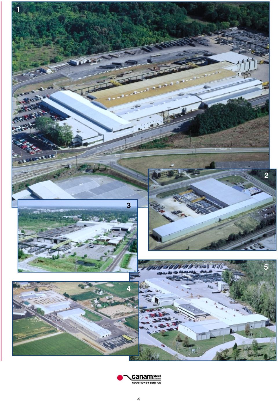
4 7 6 8 Gold Hill Vancouver Issaquah 4 Spokane Sunnyside Calgary 8 Wayzata Chicago 5 Overland Park Washington Indianapolis Détroit 2 Columbus Peru 9 Mississauga Québec 7 Saint-Gédéon Moncton Saint-Joseph Boucherville Laval Brockville Poland Spring Chittenango 6 Boston Madison Wynnewood 1 Baltimore Point of Rocks Purcellville Virginia Beach 9 Los Angeles Carlsbad Peoria Cordova Lawrenceville 11 Ciudad Juárez 3 Jacksonville San Antonio Chihuahua 10 Monterrey México 11 West Palm Beach Hypoluxo Deerfield Beach 10 Plant Canam Sales Office PLANTS UNITED STATES 1 Point of Rocks, Maryland 2 Columbus, Ohio 3 Jacksonville, Florida 4 Sunnyside, Washington 5 Washington, Missouri CANADA 6 Saint-Gédéon, Quebec 7 Boucherville, Quebec 8 Calgary, Alberta 9 Mississauga, Ontario MEXICO 10 Monterrey, Nuevo León 11 Ciudad Juárez, Chihuahua steel Corporation 5

5 GUIDING PRINCIPLES QUALITY ASSURANCE Total client satisfaction: exceptional service Excellent relations with our personnel First quality products: non-negotiable Low-cost producer Clean and orderly working environment Good corporate citizen steel Corporation 6

6 QUALITY ASSURANCE PLANT AND PRODUCT CERTIFICATIONS Over the years, we have established strict quality standards. All our welders, inspectors, and quality assurance technicians are certified by the American Welding Society or the Canadian Welding Bureau. We do visual inspections on 100% of the welded joints and non-destructive testing if required. Canada United States Mex. Plants Columbus, OH Sunnyside, WA Jacksonville, FL Point of Rocks, MD Washington, MO Boucherville, QC Saint-Gédéon, QC Mississauga, ON Calgary, AB Juarez, CHIH Monterrey, NL SJI Yes Yes Yes Yes Yes Yes Yes Yes Yes Yes AISC Cbd, Cbr, P Cbd, P Cbd Cbd, Cbr, P, F CWB Yes Yes Yes Yes Yes ISO UL Steel Deck Hambro Steel Deck & Hambro Steel Deck Hambro Steel Deck Hambro ULC Steel Deck Hambro Steel Deck Steel Deck ICBO Steel Deck & Plant Hambro Plant FM Steel Deck Steel Deck Steel Deck Steel Deck Steel Deck Steel Deck SJI: Steel Joist Institute AISC: American Institute of Steel Construction CWB: Canadian Welding Bureau ISO: International Organization for Standardization UL: Underwriters Laboratories ULC: Underwriters Laboratories of Canada ICBO: International Conference of Building Officials FM: Factory Mutual Cbd: Complex Steel Building Structures Cbr: Major Steel Bridges P: Sophisticated Paint Endorsement F: Fracture Critical Endorsement Canam has been producing open web steel joists for the last 40 years and has developed expertise in engineering and fabrication to better serve our customers with quality products. With five plants in the United States, three in Canada, and two in Mexico, the Canam team can deliver all types of joists where and when you need them from any of our SJI certified plants. In our search for quality, Canam has introduced a series of small cold formed channels to provide individual web members for most steel joists spanning over thirty feet. These straight web members allow an easier weld with the chord members. PAINT Canam s standard shop paint is GRAY primer. Other primer colors may be available at some locations. The typical shop applied primer that is used to coat steel joists and joist girders is a dip-applied, air dried paint. The primer is intended to be an impermanent and provisional coating which will protect the steel for only a short period of exposure in ordinary atmospheric conditions. Since most steel joists and joist girders are primed using a standard dip coating, the coating may not be uniform and may include drips, runs, and sags. Compatibility of any coating, including fire protective coatings, applied over standard shop primer shall be the responsibility of the specifier and/or painting contractor. The primer coating may require field touch-up/repair. The joist manufacturer shall not be responsible for the condition of the primer if it is not properly protected after delivery. ENGINEERING & DRAFTING Our engineering staff is ready and willing to help you with any technical matters you may have with the use of open web steel joists. We have developed a taste for technically challenging projects. We like to innovate and find what s best for our customers. Canam has developed enough drafting capacity so that 100% of our drawings are done by Canam employees. Canam is not using sub-contractors to perform any of our technical work. This way, we can ensure quick response time, quality, and consistency to our customers. steel Corporation 7

7 DETAILING WITH OPEN WEB STEEL JOISTS COMBINED BRIDGING TABLES K-SERIES NUMBER OF ROWS OF BRIDGING** Refer to the K-Series Load Table and Specification Section 6 for required bolted diagonal bridging. Distances are Joist Span lengths See Definition of Span on page 49. *Section Number Row Rows Rows Rows Rows #1 Up thru 16 Over 16 thru 24 Over 24 thru 28 #2 Up thru 17 Over 17 thru 25 Over 25 thru 32 #3 Up thru 18 Over 18 thru 28 Over 28 thru 38 Over 38 thru 40 #4 Up thru 19 Over 19 thru 28 Over 28 thru 38 Over 38 thru 48 #5 Up thru 19 Over 19 thru 29 Over 29 thru 39 Over 39 thru 50 Over 50 thru 52 #6 Up thru 19 Over 19 thru 29 Over 29 thru 39 Over 39 thru 51 Over 51 thru 56 #7 Up thru 20 Over 20 thru 33 Over 33 thru 45 Over 45 thru 58 Over 58 thru 60 #8 Up thru 20 Over 20 thru 33 Over 33 thru 45 Over 45 thru 58 Over 58 thru 60 #9 Up thru 20 Over 20 thru 33 Over 33 thru 46 Over 46 thru 59 Over 59 thru 60 #10 Up thru 20 Over 20 thru 37 Over 37 thru 51 Over 51 thru 60 #11 Up thru 20 Over 20 thru 38 Over 38 thru 53 Over 53 thru 60 #12 Up thru 20 Over 20 thru 39 Over 39 thru 53 Over 53 thru 60 ** Last digit(s) of joist designation shown in Load Table. ** See Section 5.11 of the K-Series specification for additional bridging required for uplift design. MAXIMUM JOIST SPACING FOR HORIZONTAL BRIDGING **BRIDGING MATERIAL SIZE K-SERIES Round Rod Equal Leg Angles HR = Hot Rolled CF = Cold Formed 1-1/8 CF 1-3/8 CF 1-5/8 CF 1-7/8 CF 2-1/8 CF SECTION 1/2 round 1 HR 1-1/4 HR 1-1/2 HR 1-3/4 HR 2 HR 2-1/2 HR NUMBER* r =.13 r =.20 r =.25 r =.30 r =.35 r =.40 r =.50 1 thru and ** Refer to last digit(s) of Joist Designation ** Connection to Joist must resist 700 pounds Certain joists require bolted diagonal bridging for erection stability for spans less than 60 feet. The chart below lists those designations and the minimum spans at which bolted diagonal bridging is required. All joists over 60 feet require erection stability bridging. 12K1 23 ft. 22K4 34 ft. 26K10 49 ft. 24LH03 35 ft. 14K1 27 ft. 22K5 35 ft. 28K6 40 ft. 24LH04 39 ft. 16K2 29 ft. 22K6 36 ft. 28K7 43 ft. 24LH05 40 ft. 16K3 30 ft. 22K7 40 ft. 28K8 44 ft. 24LH06 45 ft. 16K4 32 ft. 22K9 40 ft. 28K9 45 ft. 28LH05 42 ft. 16K5 32 ft. 24K4 36 ft. 28K10 49 ft. 28LH06 46 ft. 18K3 31 ft. 24K5 38 ft. 28K12 53 ft. 28LH07 54 ft. 18K4 32 ft. 24K6 39 ft. 30K7 44 ft. 28LH08 54 ft. 18K5 33 ft. 24K7 43 ft. 30K8 45 ft. 32LH06 47 ft. 18K6 35 ft. 24K8 43 ft. 30K9 45 ft. 32LH07 47 ft. 20K3 32 ft. 24K9 44 ft. 30K10 50 ft. 32LH08 55 ft. 20K4 34 ft. 26K5 38 ft. 30K11 52 ft. 36LH07 47 ft. 20K5 34 ft. 26K6 39 ft. 30K12 54 ft. 36LH08 47 ft. 20K6 36 ft. 26K7 43 ft. 18LH02 33 ft. 36LH09 57 ft. 20K7 39 ft. 26K8 44 ft. 20LH02 33 ft. 20K9 39 ft. 26K9 44 ft. 20LH03 38 ft. On Canam s framing plans, the erection stability bridging lines are identified with the following symbol and notation: ES APPROVER / ERECTOR NOTE: Except for column joists noted as OC, All ERECTION STABILITY bridging lines shall be installed prior to the slackening of hoisting lines. steel Corporation 8

8 DETAILING WITH OPEN WEB STEEL JOISTS COMBINED BRIDGING TABLES For KCS-Series joists, use the tables for K-Series with an equivalent section number, as shown in the chart below: BRIDGING JOIST TABLE DESIGNATION SECT. NO. 10KCS1 1 10KCS2 1 10KCS3 1 12KCS1 3 12KCS2 5 12KCS3 5 14KCS1 4 14KCS2 6 14KCS3 6 16KCS2 6 16KCS3 9 16KCS4 9 16KCS5 9 18KCS2 6 18KCS3 9 18KCS KCS KCS2 6 20KCS3 9 20KCS KCS KCS2 6 22KCS3 9 22KCS KCS KCS2 6 24KCS3 9 24KCS KCS KCS2 6 26KCS3 9 26KCS KCS KCS2 6 28KCS3 9 28KCS KCS KCS3 9 30KCS KCS5 12 BRIDGING BOLT SIZES SECTION MINIMUM SERIES NUMBER BOLT SIZE K ALL 3/8 A307 LH/DLH /8 A307 LH/DLH /2 A307 or 3/8 A325 DLH 18 & 19 5/8 A307 or 1/2 A325 LH-DLH MAX. SPACING HORIZONTAL *SECTION OF LINES OF BRACING NUMBER BRIDGING FORCE lbs 02,03, , , , , , , , Number of lines of bridging is based on joist clear span dimensions. *Last two digits of joist designation shown in load table K, LH & DLH SERIES JOISTS MAXIMUM JOIST SPACING FOR DIAGONAL BRIDGING BRIDGING ANGLE SIZE - (Equal Leg Angles) HR = Hot Rolled CF = Cold Formed 1-1/8 CF 1-3/8 CF 1-5/8 CF 1-7/8 CF 2-1/8 CF JOIST 1 HR 1-1/4 HR 1-1/2 HR 1-3/4 HR 2 HR DEPTH r =.20 r =.25 r =.30 r =.35 r = LH SERIES JOISTS MAXIMUM JOIST SPACING FOR HORIZONTAL BRIDGING SPANS OVER 60 REQUIRE BOLTED DIAGONAL BRIDGING **BRIDGING ANGLE SIZE - (Equal Leg Angle) HR = Hot Rolled CF = Cold Formed 1-1/8 CF 1-3/8 CF 1-5/8 CF 1-7/8 CF 2-1/8 CF SECTION 1 HR 1-1/4 HR 1-1/2 HR 1-3/4 HR 2 HR 2-1/2 HR NUMBER* r =.20 r =.25 r =.30 r =.35 r =.40 r =.50 02, 03, ** Refer to last two digits of Joist Designation. ** Connection to joist must resist force listed in Table of the LH-Series specification. steel Corporation 9

9 DETAILING WITH OPEN WEB STEEL JOISTS GIRDER AND JOIST CONNECTIONS 3 3/4 ø BOLTS 5 GAGE 1-1/2 3/4 ø BOLTS 5 GAGE 2 3/4 ø BOLTS 5 GAGE 7-1/2 7-1/2 7-1/ /2 1 STABILIZER PLATE 1 STABILIZER PLATE 1 STABILIZER PLATE GIRDER CONNECTION BOLTS NOT BY CANAM A GIRDER CONNECTION BOLTS NOT BY CANAM B GIRDER CONNECTION BOLTS NOT BY CANAM C 3 3/4 ø BOLTS 5 GAGE 7-1/2 HALF STD GA 3/4 ø BOLTS 4 LH & DLH 1/2 ø BOLTS 3-1/2 K 2-1/2 3/4 ø BOLTS 4 LH & DLH 1/2 ø BOLTS 3-1/2 K K LH 6 K LH K LH 1 STABILIZER PLATE GIRDER CONNECTION BOLTS NOT BY CANAM D JOIST CONNECTION BOLTS NOT BY CANAM E 1 STABILIZER PLATE JOIST CONNECTION BOLTS NOT BY CANAM F 1-1/2 3/4 ø BOLTS 4 LH & DLH 1/2 ø BOLTS 3-1/2 K 2 3/4 ø BOLTS 4 LH & DLH 1/2 ø BOLTS 3-1/2 K 2-1/2 3/4 ø BOLTS 4 LH & DLH 1/2 ø BOLTS 3-1/2 K 3 K LH 1/2 K LH K LH 1 STABILIZER PLATE JOIST CONNECTION BOLTS NOT BY CANAM H 1 STABILIZER PLATE JOIST CONNECTION BOLTS NOT BY CANAM K DLH18 and DLH19 will have girder standards. K LH 1 JOIST CONNECTION BOLTS NOT BY CANAM STABILIZER PLATE L steel Corporation 10

10 DETAILING WITH OPEN WEB STEEL JOISTS GIRDER AND JOIST BEARING HORIZ. BRIDGING CUT TO FIT IN FIELD LAP TO BE 2 MIN USE ALL DROPS. See page 10 for standard girder and joist connections at columns. Joists not falling directly at a column line have to be welded and/or bolted depending on conditions. As per OSHA, any joists in bays over 40 and bearing on steel framing have to be bolted unless if the joists are assembled on the ground into panels and then set in place. Minimum welds are two 1/8 x 1 long fillet welds for K-Series and two 1/4 x 2 long fillet welds for LH and DLH-Series. K-Series joists shall bear at least 2 1/2 on steel and 4 on masonry while LH, DLH, and girder shall bear a minimum of 4 on steel and 6 on masonry. PLAN 2 2 1/8 1 TYP MIN BRIDGING DETAILS 1/8 1 TYP MIN SEE PLAN FOR PIECE MARK BRIDGING ANCHOR PIECE MARK BAC = 2 1/2 x 2 1/2 x 3/16 x 2 1/2 LONG ATTACH WITH: 1/2 EXP BOLT (NOT BY CANAM) BRIDGING ANCHOR PIECE MARK BAC = 2-1/2 x 2-1/2 x 3/16 x 2-1/2 LONG ATTACH WITH: 1/2 EXP BOLT (NOT BY CANAM) 1/4 2 LH SERIES 1/4 2 TYP. MIN. 1/8 1 K SERIES 1/8 1 TYP. MIN. WELDED-X BRIDGING SEE PLAN FOR PIECE MARK 1/8 2 MIN KNEE BRACE ONLY IF REQUIRED BY DESIGN SEE PLAN FOR LOCATIONS TYP MIN 1/8 1 steel Corporation 11

11 DETAILING WITH OPEN WEB STEEL JOISTS SQUARE ENDS ADDED MEMBERS Whenever joists are bottom chord bearing, a row of bolted diagonal cross bridging should be installed from joist to joist at or near the bearing location to provide lateral erection stability. OF PANEL POINT MORE THAN 3 3/16 as specified SQUARE END OF POINT LOAD The weight of walls, signage, facia, etc. supported at the end of a cantilever square end must be shown on the contract drawings to be properly considered in the joist design. FULL DEPTH CANTILEVER END OF PANEL POINT FIELD INSTALLED MORE THAN 3 ANGLE BRACE, EACH SIDE NOT BY CANAM~MINIMUM OF POINT LOAD LEG THICKNESS 3/16. TYPICAL JOIST REINFORCEMENT AT CONCENTRATED LOADS Joists, including KCS-Series, are not typically designed for localized bending from point loads. Concentrated loads must be applied at joist panel points or field strut angles must be utilized as shown. Canam can provide a specially designed joist with the capability to take point loads without the added struts, if this requirement and the exact location and magnitude of the loads are clearly shown on the contract drawings. Also, Canam can consider the worst case in both the shear and bending moment for a traveling load with no specific location. When a traveling load is specified, the contract drawings should indicate whether the load is to be applied at top or bottom chord, and at any panel point, or at any point with the local bending effects considered. UPLIFT Where uplift is a design consideration, the NET uplift value shall be provided on the contract drawings. Additional lines of bridging will be required at the first bottom chord panel points as shown. UPLIFT BRIDGING: 1 ROW OF HORIZONTAL FIRST BOTTOM CHORD PANEL POINT ON EACH END OF JOIST AS SHOWN. TYPICAL ALL JOISTS, ALL BAYS, IN ADDITION TO STANDARD BRIDGING SHOWN ON PLAN. FIRST BOTTOM CHORD PANEL POINT steel Corporation 12

12 DETAILING WITH OPEN WEB STEEL JOISTS SLOPED SEATS The shoe depth must always be specified at the gridline. For joists on which the left and right bearings are not at the same level (sloped joist), the exterior and interior shoe depths are determined in such a way as to respect the depth at the gridline. Interior Shoe Depth Shoe Depth at gridline Exterior Shoe Depth Interior Shoe Depth Shoe Depth at gridline Exterior Shoe Depth Interior Shoe Depth Exterior Shoe Depth Shoe Depth at gridline Interior Shoe Depth Exterior Shoe Depth Shoe Depth at gridline The bearing depth should be increased at sloped joists to insure an adequate depth of bearing seat assembly at the inside end or at the outside end, which depends on which bearing end (left or right) is higher. x 12 Shoe Depth at gridline 2 1/2 MIN x /2 MIN Shoe Depth at gridline A A Reference lines (gridline) are always at center of bearing steel or inside face of wall. MINIMUM SHOE DEPTH AT GRIDLINE (in.) A Joist Sloped (x / 12) (in.) NOTE: Calculations are based on a top chord vertical leg of 2-1/2 (all K-Series and up to LH07). steel Corporation 13

13 DETAILING WITH OPEN WEB STEEL JOISTS FIELD BOLTED SPLICE Field bolted splices can be provided on any joist type when required for shipment or due to site constraints, such as a retrofit use. Note that spliced joists are normally fabricated as one complete piece in Canam s shops, and are then separated for shipment. In assembling the joist, the erector must match mates. The joist mates will be marked 1L and 1R or 2L and 2R and so on in addition to regular joist piece marks. Two dissimilar mates will not fit together properly. The metal tag for the left half of the spliced joists will be placed near the bearing end, and this end must be placed to match the tagged end on the framing plan. The metal tag for the right half is placed on the left end of this half, near the splice. PITCHED JOISTS Canam can provide longspan joists with a variety of pitched chord configurations. TOP CHORD SINGLE PITCHED UNDERSLUNG TOP CHORD SINGLE PITCHED SQUARE ENDS SPLICE TOP CHORD DOUBLE PITCHED UNDERSLUNG JOIST TOP CHORD SPLICE CONNECTION 1 TOP CHORD DOUBLE PITCHED SQUARE ENDS DUCT OPENINGS JOIST BOTTOM CHORD SPLICE CONNECTION NOTE: QUANTITY AND ARRANGEMENT OF BOLTS AND PLATES MAY VARY. ALL BOLTS ARE TO BE HIGH STRENGTH. (A325 OR A490) TYP. SPLICE DETAIL Open web steel joists allow the passage of pipes, conduits, and ducts through the joist. The specifier shall clearly show the size and exact location of ducts which have a fixed location and cannot be field located around the joist webs. To maximize the duct openings in a joist girder, the joist girder can be specified as a VG type. By aligning the vertical web members of the girder with the joists it supports, the duct opening in the girder, between the joists, is maximized. VG GIRDER DUCT steel Corporation 14

14 DETAILING WITH OPEN WEB STEEL JOISTS MAXIMUM DUCT OPENINGS DIMENSIONS OF FREE OPENINGS FOR VARIOUS JOIST AND JOIST GIRDER CONFIGURATIONS NOTE: Since dimension P could vary with the final design, final dimensions of free openings should be verified with Canam. P P P P H D L R S S H D L R S S WEB CONFIGURATIONS (in.) OPENINGS (in.) H P D S L R JOISTS When duct-opening dimensions exceed the limits above, some web members must be removed. The shear forces are then transferred through the adjacent web members of the top and bottom chords. The chords will need to be reinforced; this will limit the maximum height of the free opening as well. The maximum opening height should be limited to the joist depth minus 8 (200 mm). If the opening height cannot be limited to this value, contact Canam. Because the shear forces carried by the web members increase along the joist toward the bearing, the location of the duct opening is more critical near the bearings where more shear forces must be transferred through the top and bottom chords. For this reason, the duct-opening center must be located away from a bearing by a distance of at least 2.5 times the joist depth. The best location (for economical reasons) is at the mid span of the joist. WEB CONFIGURATIONS (in.) OPENINGS (in.) H P D S L R JOISTS WEB CONFIGURATIONS (in.) OPENINGS (in.) H P D S L R JOIST GIRDERS Location must be greater than 2.5 x H 4 min. H 4 min. steel Corporation 15

15 ENGINEERING WITH OPEN WEB STEEL JOISTS LOAD / SPAN DESIGN SPECIAL LOADS As an alternate to a standard joist designation in the load tables, Canam can design and manufacture a special load/span joist for the exact uniform load requirements. A load/span joist should be designated as follows: ddksptl/ll ie. 24KSP300/175 dd = depth in inches tl = total load in plf ll = live load in plf Live load deflection will be governed by L/360 for floors or L/240 for roof unless noted otherwise on the contract drawings. A load/span joist can be used for either K, LH or DLH-Series. DEAD LOAD= PT. LD. LIVE LOAD= PT. LD. PT. LD. SLOPED JOISTS For sloped joists, the load and span shall be defined as outlined below. This allows the use of the load tables for joists with slopes larger than 1/2 inch per foot. Span: The span of a parallel chord sloped joist shall be defined by the length along the slope. Minimum depth, loadcarrying capacity, and bridging requirements shall be determined by the sloped definition of span. The Standard Load Table capacity shall be the component normal to the joist. Load: Where the design live load is applied vertically over the plan length and the design dead load is applied vertically over the sloped length, select a joist with Load-Table capacity = LL*cos 2 α + DL*cos α Canam will automatically design for the component of the load parallel to the joist which acts as a top chord axial load. α SPAN α α LL DL α α LOAD-TABLE CAPACITY LL * cos 2 α DL * cos α Canam s design programs allow for the consideration of numerous special loading conditions. Where special loads, such as snow drifting or equipment loads, will be placed on a joist, the loading information can best be conveyed by using a load diagram such as the sample shown here. It is important for the load diagram to clearly indicate which point loads are applied at the joist top chord, and which are suspended from the bottom chord. And it is important to clearly locate mechanical loads to avoid delays in joist fabrication. Unless specifically instructed otherwise, it is assumed that field added strut angles will be utilized as described on page 12. Canam has two design capabilities which can be used to help accommodate variable loading conditions. First, a joist or girder can be designed with multiple loading cases. Each element of the joist or girder is then sized to handle the worst forces generated by any one of the loading conditions. For example, a joist may have a case one which has a uniform snow load and will create the controlling bending moment. Case two might have a snow drift together with a reduced uniform snow load, which may be a more severe condition for shear. A second capability is the ability to design for a traveling load. For each element of the joist or girder, the forces are determined for the most critical location of the load along the joist length. Traveling loads can be specified as being at any panel point along the top or bottom chord, or at ANY point along the top or bottom chord. By specifying a traveling load to be applied at ANY point, miscellaneous loads within the specified limit can be applied at any time during the life of the structure without the need for reinforcement or field added members. Canam s engineering staff can help find solutions for almost any special loading condition. steel Corporation 16

16 ENGINEERING WITH OPEN WEB STEEL JOISTS END MOMENTS Tie joists (joists at column lines) or joist girders can be successfully used as part of a moment frame in the structure. The frame analysis shall be performed by the specifier, and the resultant wind/seismic and continuity moments shall be shown on the contract drawings. For purposes of the frame analysis, the moment of inertia of a joist or joist girder can be approximated by the formulas on page 50, 73, 76, and 78, respectively, in this catalog. Detail A shows the suggested method of presenting the moment values, as well as the directions in which they will be applied. M M WL LL DETAIL A M M LL WL In addition to providing the end moment values on the contract drawings, the specifier must give due consideration to the connections in order to properly develop the end moments. At the joist or girder bottom chord, the connection can be made simply by welding the bottom chord directly to the column stabilizer plate (see Detail B). The typical gap provided between the bottom chord angles is one inch. As shown in Detail C, at the top chord considerable eccentricity will develop if the connection is made at the base of the bearing seat on a typical underslung end. A moment plate shall be used to allow direct transfer from the top chord to the column or abutting joist, similar to Details D and E. The specifier shall show the size of the plate and the required welds on the contract drawings. These moment plates are not included in Canam s bid, unless specified otherwise. Canam will presume that all continuity moments are induced by the live load, and unless otherwise instructed by the specifier, will presume that no dead load moment is present. It is Canam s standard practice to instruct the joist erector to complete the connection of the bottom chords to the columns only after all dead loads are applied. Thus, the joist will act only as a simply supported truss for the dead load case. Where end moments have been specified, Canam will first design the joist or joist girder as a simply supported member with the full gravity loads applied. This ensures adequate strength during construction before the end moment connection is completed, and also provides additional redundancy to the structure in the event that the moment connection is not successfully completed in the field. Canam will then apply all the appropriate combinations of the wind/seismic and continuity moments as a separate load case. Each chord and web member in the joist or joist girder will be designed for the worst condition of either the simple span or end moment case. e P M = P x e DETAIL C DETAIL D MOMENT PL TYP. (NOT BY CANAM) DETAIL B DETAIL E steel Corporation 17

17 ENGINEERING WITH OPEN WEB STEEL JOISTS STANDING SEAM ROOFS Where a standing seam roof is attached directly to the joist top chord, or any other instance where decking will not provide lateral support on the top chord, Canam will design a bridging system to provide the required top chord lateral support, in accordance with the following specifications of sections 5.8(g) or 104.9(g). STANDING SEAM ROOF SYSTEM JOIST TOP CHORD Ted Constant Center, Old Dominion University, Norfolk, VA JOISTS LONGER THAN SJI Canam has the capability to build joists, trusses, and joist girders with spans and depths beyond the limits of the Load Tables. The DLH-series Load Table extends to depths of 72 inches and spans of 144 feet. Canam can fabricate special joists with depths of over 10 feet and lengths over 200 feet. Special consideration is required for these very large joists, and attempting to select a standard joist from a load table may be an over-simplification of the true loading conditions and design requirements. Canam recommends that any joist that exceeds the range of the DLH-series Load Table be labeled as a special joist with a load diagram provided to allow accurate design of the joist. The load diagram should clearly indicate if the joist self weight is included in the design loads, or if the loads shown are only the superimposed loads to which self weight must be added. Due consideration must also be given to camber, deflection, bridging or bracing, and erection. Please consult Canam for assistance in specifying these joists. Canam has extensive experience in providing joists beyond the range of the Load Tables, including these recent projects: * Ford Field Stadium Detroit, MI 128 joists inches deep, 166 feet long, shipped in 2 pieces * Ted Constant Convocation Center Old Dominion University, Norfolk, VA 17 joists, 168 inches deep, 238 feet long, shipped in 3 pieces * Belmont University Nashville, TN 20 joists, 170 inches deep, 211 feet long, shipped in 3 pieces * York High School Elmhurst, IL 37 joists, 120 inches deep, 202 feet long, shipped in 2 pieces * Jordan Valley Park Expo Center Springfield, MO 35 pieces, 96 inches deep, 150 feet long, shipped in 2 pieces * Dubuque Riverfront Education Dubuque, IA 13 pieces, 168 inches deep bowstring, 150 feet long, shipped in 2 pieces * Idaho Sports Center Nampa, ID 11 pieces, 120 inches deep scissors, 175 feet long, shipped in 2 pieces * Palm Beach County Convention Center West Palm Beach, FL 179 pieces, 80 inches deep, 150 feet long, shipped in 2 pieces * Mohegan Sun Podium Uncasville, CT 43 pieces, 96 inches deep, 166 feet long, shipped in 3 pieces * Angelo State University s Junell Center San Angelo, TX 33 pieces, 120 inches deep, 224 feet long, shipped in 3 pieces steel Corporation 18

18 ENGINEERING WITH OPEN WEB STEEL JOISTS Junell Center, San Angelo, TX Junell Center, San Angelo, TX Junell Center, San Angelo, TX steel Corporation 19

19 SPECIAL SHAPES ENGINEERING WITH OPEN WEB STEEL JOISTS As a minimum, the dimensions and information shown in the sketches must be provided for joists with special profiles. Special shape joists do not to need to have a standard SJI designation. The load/span method, as described in this section, can be utilized for special shape joists with supplementary load diagrams, as shown in the special loads section. For joist lengths over 100 feet, a field bolted splice will likely be required for shipment in halves or thirds. Joist depths over 8 feet will require special shippping arrangements. When the total depth of the joist profile reaches 15-6, it cannot be shipped as a unit and some form of field assembly will be required. For any joist shipped in halves, thirds, or pieces, it is critical that the match-marked parts be joined. The parts are not interchangeable. Special consideration should be given to the camber of special joists, particularly where they are adjacent to other framing or deck supports. If Canam is provided with the actual design dead load, special camber can be provided. GABLE JOIST SCISSOR JOIST Idaho Sports Center, Nampa, ID steel Corporation 20

20 SPECIAL SHAPES ENGINEERING WITH OPEN WEB STEEL JOISTS Gable joists are commonly specified as bottom chord bearing, as shown in the sketch. The specifier should consider the use of the end walls as an anchorage point for the joist bridging, which is critical to provide lateral stability. Gable joists need not be symmetric. For any double pitched configuration, an offset ridge can be provided. Note that barrel and scissor joists are modeled with pin and roller supports and the truss will deflect horizontally. The specifier must make provisions to allow for this horizontal movement. Any special limitations on the amount of allowed horizontal deflection must be clearly shown on the contract drawings. To obtain the most economical design, Canam will vary the configuration of the joist web members within the overall profile provided in the sketch on the contract drawings. If a particular web geometry is required to create specific openings for mechanical needs, catwalks, or architectural reasons, these requirements should be noted with the profile, and specific dimensions locating the joist panel points should be provided. BOWSTRING JOIST R= BARREL JOIST R= R= Buckeye Fried Chicken, Columbus OH Buckeye Fried Chicken, Columbus OH steel Corporation 21

21 OSHA HIGHLIGHTS ENGINEERING WITH OPEN WEB STEEL JOISTS These pages summarize the key provisions of the revised OSHA steel erection standard, 29 CFR Part The complete OSHA rule for steel joists is included as an appendix to the Steel Joist Institute Specifications in this publication. The two most critical elements to the safe erection of steel joists are to limit or eliminate the need to walk un-bridged joists, and to properly and completely install the bridging as soon as possible. Canam advocates erection methods whereby the erector is not required to walk an un-bridged joist to release the hoisting cable. This can be accomplished by using erection stability bridging, working from a man-lift or other ground support, setting the joists in pre-assembled panels, or using a self-releasing mechanism on the crane. JOISTS AT COLUMNS Joists at column lines, which are not framed in at least two directions by solid web structural steel members, shall have a field-bolted connection at the joist bearing seat. In addition, joists at column lines must also have bottom chord extensions (BCX s). The BCX must extend to a vertical stabilizer plate. The stabilizer plate is to be a minimum size of 6 inches by 6 inches, with 3 inches extended below the bottom chord with a 13/16 inch hole to provide for a cable attachment. Where a steel joist does not lie directly along the column line, the joist nearest the column, on each side of the column, shall have field-bolted bearing seats. However, the bottom chord extensions may be omitted where it is not practical to provide them near the column. ERECTION STABILITY BRIDGING The forty foot rule no longer applies for the requirement of a bolted diagonal bridging line. The spans in the shaded portions of the Load Tables require a row of bolted diagonal bridging. Note that there are many designations and spans of less than forty feet that are shaded and require a row of bolted diagonal bridging. But there are also many designations and spans greater than forty feet which are not shaded and do not require a bolted diagonal bridging row. BOLTED BEARING SEATS Joists in bays of 40 feet or more shall be fabricated and installed with a field-bolted connection from the joist bearing seat to the steel frame. The bay length is the length from center to center of steel supports, or center of steel to face of wall. An exception to this rule is made for those cases where constructibility does not allow the bolted connection, or where multiple joists are pre-assembled and set in panels. Typically, the field-bolted bearing seat connection will be made with ASTM-A307 bolts in slotted holes and is considered a temporary connection. The final connection should be made by welding or as specified by the project structural engineer of record. COLUMN JOIST STABILITY The OSHA rules require that steel joists at or near columns that span 60 feet or less be designed with sufficient strength to carry the self-weight of the joists and the weight of one erector. This allows the hoisting cable to be released without the need for erection stability bridging. It is only possible to meet this column joist requirement if certain conditions are met, and these joists will be identified with the symbol OC on Canam s framing plans to show that they are OSHA column joists. In spite of this requirement, Canam advocates alternate erection methods that allow the hoisting cable to be released without an erector walking an unbridged joist. For the joists identified as OSHA column joists ( OC ) Canam will utilize a complex formula to check the erection stability. This check will conservatively assume that bottom chord extensions are not present to allow for the possibility of column joists that are near, rather than at, column lines and may not have BCX s. If the column joist does not initially pass the stability check, Canam will modify the joist design such that the joist will pass. Typically, this will involve increasing the joist top chord size. In order for a joist to be considered as an OC column joist, it must have standard parallel chords with standard under-slung bearing ends, and must have a slope of 1/4 inch per foot or less. In addition, the erector must secure both ends with two wrench tight bolts (or the equivalent for ends not at steel frames) and the joist must be placed plumb and true. For sloped, pitched, bottom bearing, or other special column joists, it will not be possible to apply the stability formula and check for erection stability. These column joists will be identified as DT joists on Canam s framing plans, and will be supplied with a Danger Tag hung on the joist to warn the erector that the joist has not been designed to support an employee without bridging installed, and alternate erection methods must be used. Beyond 60 foot spans, OSHA does not have special stability requirements for column joists. Column joists that span more that 60 feet should be set in tandem with all bridging installed or by the erector s alternate means of erection. steel Corporation 22
22 OSHA HIGHLIGHTS ENGINEERING WITH OPEN WEB STEEL JOISTS BUNDLE SIZES AND PLACEMENT Bridging bundles shall be limited to 1000 pounds maximum. The bridging bundle shall be placed across a minimum of three joists, within one foot of a secured end of the joists. Where Canam supplies metal decking, the deck bundles shall be limited to 4000 pounds maximum. The deck bundles should not be placed before the joist ends are attached and all bridging has been installed, except where the OSHA rule allows the deck bundle to be placed after only one row of bridging is installed and other special conditions are met. BOTTOM BEARING JOISTS Bolted diagonal bridging is required over or near the support for all bottom chord bearing joists. This includes both square-end joists, and cantilever-square-end joists. This is a general summary of the OSHA requirements, but is not intended to constitute legal advice. Canam does not assume responsibility for compliance with OSHA requirements. This is a sample Danger Tag which is hung on joists marked DT on the drawings. This block of notes will appear on all of Canam s framing plans. ERECTORS NOTE: ALL JOISTS IN BAYS WITH CENTER OF STEEL TO CENTER OF STEEL OR CENTER OF STEEL TO INSIDE FACE OF WALL OF 40-0 OR GREATER ARE TO BE BOLTED FOR ERECTION AT STEEL BEARING ENDS. THIS REQUIREMENT MAY BE WAIVED UNDER CERTAIN CONDITIONS. CONSULT THE OSHA SAFETY STANDARDS FOR SPECIFICS. THE FINAL CONNECTIONS ARE TO BE WELDED AS INDICATED ON THESE DRAWINGS. - COLUMN JOIST OR JOIST NEAR A COLUMN DESIGNATED AS (OC), SHALL NOT BE RELEASED FROM THE HOISTING LINE UNTIL THE JOIST IS DETERMINED TO BE PLUMB AND TRUE AND EACH END IS SECURED WITH AT LEAST TWO BOLTS OF THE SAME SIZE AND STRENGTH AS SHOWN ON THESE DRAWINGS, DRAWN UP WRENCH TIGHT OR EQUIVALENT. - IF A COLUMN JOIST IN BAYS 60-0 OR LESS IS DESIGNATED AS (DT): * THIS JOIST HAS NOT BEEN DESIGNED TO SUPPORT AN EMPLOYEE WITHOUT BRIDGING INSTALLED. * THIS JOIST IS NOT AN OSHA JOIST DESIGNED FOR STABILITY PER SUBPART R (3) DUE TO ITS SPECIAL PROFILE OR SLOPED CONDITION. * SPECIAL ERECTION METHODS MUST BE INCORPORATED. * DO NOT ALLOW EMPLOYEES ON THIS JOIST UNTIL ADEQUATELY STABILIZED. CONSULT THE OSHA SAFETY STANDARDS FOR SPECIFICS. - IN BAYS GREATER THAN 60-0, JOIST AT OR NEAR COLUMNS SHALL BE ERECTED IN TANDEM (PAIR) WITH AN ADJACENT JOIST. ALL BRIDGING MUST BE INSTALLED BEFORE LIFTING AND THE PAIR OF JOISTS MUST BE SECURED TO THEIR SUPPORT BEFORE RELEASING THE HOISTING LINE. THIS REQUIREMENT MAY BE WAIVED UNDER CERTAIN CONDITIONS. CONSULT THE OSHA SAFETY STANDARDS FOR SPECIFICS. steel Corporation 23
23 FLOOR VIBRATION ENGINEERING WITH OPEN WEB STEEL JOISTS Floor vibration has become a structural design issue due to the increased use of longer spans, more open areas and lighter floor systems. The building structural designer must analyze floor vibration and its effect on the building end users and specify the proper characteristics to reduce vibration. The behavior of two-way flooring systems has been studied using models and in-situ testing. Several simplified equations to predict floor behavior and damping values for walking induced vibration have been established according to the type of wall partitions and floor finishes. These equations are now part of Steel Design Guide #11, jointly published by the American and Canadian Institutes of Steel Construction in This guide covers different types of floor vibrations and is one of the main references on the subject. The formulas shown in Steel Design Guide #11 allow the user to define the vibration characteristics of a floor system: the initial acceleration produced by a heel drop and the natural frequency of the system. These two parameters allow the designer to verify if the floor system will produce vertical oscillations in resonance with rhythmic human activities or with enough amplitude to disturb other occupants. The amplitude of the vibrations will decay according to the type of partitions, ceiling suspensions, and floor finish. The decay rate will also influence the sensitivity of the occupants. Information about the use and architectural finishes of a building is not readily available to the joist supplier. The joist supplier usually receives only the floor drawings and general joist specifications and designation. This is the information that is used for joist design. Furthermore, when a project structural engineer has predetermined the design of a joist including spacing, depth, span, bearing support, and dead loads, the joist design alone cannot be easily modified to reduce floor vibration induced by walking below the annoyance threshold for the other occupants. The following example of this situation is for office floors where the annoyance threshold is defined as a floor acceleration of 0.5% of the gravity acceleration and with enough partitions to provide moderate damping. For floors in a shopping mall, the threshold would be an acceleration of 1.5% of the gravity acceleration. This higher threshold means that the occupants are less disturbed by vibrations produced by walking loads. TYPICAL OFFICE FLOOR INITIAL DESIGN: In the example, the floor area is 90 by 96, the joists have a 30-0 (9 150 mm) span, a 20 (approx. 500 mm) depth, and are spaced at 4-0 (1 220 mm) on center. The joists are bearing on beams at both ends on 2 1/2 (65 mm) deep seats. The assumption is that the beams will be only partially composite for vibration calculations because of the relative lack of stiffness of such a bearing seat. The beam span is 24-0 (7 315 mm) with joists bearing from both sides and acts as a single span. The floor is made of a 4 (100 mm) concrete slab, including the 1 1/2 (38 mm) steel deck profile. The loads are as follows: Structural steel 5 psf (0.24 kpa) Steel joists 4 psf (0.19 kpa) Deck-slab of 100 mm 38 psf (1.82 kpa) Ceiling, mechanical & floor finish 10 psf (0.48 kpa) Partitions 20 psf (0.96 kpa) DEAD LOAD TOTAL 77 psf (3.69 kpa) LIVE LOAD 50 psf (2.40 kpa) From the SJI K-Series load table, select a joist with a 30-0 span to support the following loads: w = 4 x ( ) = 488 plf A joist with a 20K10 designation will support 533 plf for a 30-0 span and a uniform load of 336 plf will produce a deflection equal to the span of 360 which is fine since the live load is 200 plf. By reducing the simple span deflection formula under uniform load for span/360, we obtain the following approximation of the moment of inertia: I joist = W 360 x (span) 3 / 38,000, where I joist = moment of inertia in in. 4 w 360 = uniform load producing a deflection equal to span / 360 in. plf Span = span of joist in feet I joist = 336 x (30) 3 / 38,000 = 238 in. 4 The center of gravity of the joist steel cross section can be assumed to be at mid depth. A joist chords = I joist / (depth / 2) 2 = 2.38 in. 2 The beam can be chosen from the AISC selection tables as W18 x 60 with F y = 50 ksi and a moment of inertia of 984 in. 4. ALTERNATE 1: If a slab of 5 instead of 4 is used, the dead load increases and the size of the joists and beams may also increase. Structural steel 5 psf (0.24 kpa) Steel joists 4 psf (0.19 kpa) Deck-slab of 5 50 psf (2.40 kpa) Ceiling, mechanical & floor finish 10 psf (0.48 kpa) Partitions 20 psf (0.96 kpa) DEAD LOAD TOTAL 89 psf (4.27 kpa) LIVE LOAD 50 psf (2.40 kpa) From the SJI K-Series load table, select a joist with a 30-0 span to support the following loads: w = 4 x ( ) = 536 plf steel Corporation 24
24 FLOOR VIBRATION ENGINEERING WITH OPEN WEB STEEL JOISTS The same 20K10 joist will work for a 30-0 and the properties will be the same. I joist = 336 x (30) 3 / 38,000 = 238 in. 4 A joist chords = I joist / (depth / 2) 2 = 2.38 in. 2 This time, the beam chosen from the AISC selection tables is W18 x 65 with F y = 50 ksi and a moment of inertia of 1,070 in. 4. ALTERNATE 2: Starting from the base example, consider that the structural engineer of the building clearly indicates that the size of the joists should be doubled to reduce floor vibration. Since there are no standard K-Series joists with the same depth that are twice the size of a 20K10, we will double up the joists by spacing the 20K10 joists at 2 on center. ALTERNATE 3: Combining the changes of alternates 1 and 2, we evaluate a 5 slab on 20K10 joists spaced at 2-0 on center. Using the data of those 4 conditions, with the proposed equations of Steel Design Guide #11 and considering an open floor even if the structure is designed for a possible partition load, we obtain the vibration properties shown in the comparison table below: COMPARISON OF VARIOUS ARRANGEMENTS PARAMETERS INITIAL ALTERNATE 1 ALTERNATE 2 ALTERNATE 3 DESIGN INCREASED DOUBLE JOIST DOUBLE JOIST THICKNESS OF SAME SIZE OF SAME SIZE OF SLAB AND INCREASED THICKNESS OF SLAB Peak acceleration a o with open floor (% g) 1.11% 0.87% 0.81% 0.65% Peak acceleration a o with some partitions (% g) 0.74% 0.58% 0.54% 0.44% Peak acceleration a o with full height partitions (% g) 0.44% 0.35% 0.32% 0.26% System frequency f (Hz) Joist length (ft.) Joist depth (in.) Joist spacing (ft.) Joist moment of inertia (steel) (in. 4 ) Deck depth (in.) Slab-deck thickness (in.) Slab-deck-joist dead weight (psf) Additional participating load (psf) Beam size W18 x 60 W18 x 65 W18 x 60 W18 x 65 Beam span (ft.) This comparison shows that the vibration characteristics improve by adding dead weight or by doubling the joists. One must note that the alternates 1 and 2 used did not sufficiently improve the vibration properties of the floor to lower their amplitude to below the annoyance threshold for offices. Additional calculations shown as alternate 3 indicate that using a 5 deck-slab with a 100% increase in the joist sections would lower the peak acceleration to below the annoyance threshold of 0.5% of g. The building designer controls the main parameters affecting floor vibration characteristics and he or she must make the vibration calculations to find an economical solution. The information supplied in this catalog will allow the structural engineer to evaluate the vibration properties of the floor joists during the initial design. The project structural engineer should always specify the proper slab thickness and the minimum moment of inertia of the steel joists to have a floor with vibration characteristics below the annoyance threshold based on the type of occupancy. The joist designer will then verify conformance to the minimum moment of inertia required by the building designer for the joists. steel Corporation 25
25 ENGINEERING WITH OPEN WEB STEEL JOISTS JOIST SUBSTITUTES The Steel Joist Institute has introduced a joist substitute series, the 2.5K series. SJI load tables and specifications can be found on page 37 of this catalog. Joist substitutes are intended to be used for relatively short spans. It is more economical to use joist substitutes rather than joists for spans of 10 feet and under. Canam has extended the load tables to allow the specifier to make proper selection of joist substitutes. Joist substitutes are solid members made of angles, channels, or tube steel. SPAN JOIST SUBSTITUTES 2.5K1 2.5K2 2.5K3 S (in. 3 ) Mr (k-ft.) I (in. 4 ) Span (ft.) ALLOWABLE LOADS (plf) / / / / / / / / / / / / / / 71 The figures in red represent the maximum live load to create a L/360 deflection. If L/240 is acceptable, these figures can be multiplied by DESIGN SPAN 2 2 1/2 U.N.O. 4 MIN ON MASONRY 2 1/2 MIN ON STEEL Joist substitutes can be used in many conditions. They can be used in combination with LH-Series joists. In these cases, a deeper joist substitute will be supplied or seats will be installed on a regular 2 1/2 deep section as shown below. 5 Joist substitutes can be used on sloping roofs. Seat depth for sloped joist substitutes should be selected as per the table on page 13 of this catalog. steel Corporation 26
Steel joists and joist girders are
 THE STEEL CONFERENCE Hints on Using Joists Efficiently By Tim Holtermann, S.E., P.E.; Drew Potts, P.E.; Bob Sellers, P.E.; and Walt Worthley, P.E. Proper coordination between structural engineers and joist
Joist. Reinforcement. Draft 12/7/02
 Joist Reinforcement Draft 12/7/02 1 JOIST REINFORCING The purpose of this CSD Design Aid is to provide procedures and suggested details for the reinforcement of open web steel joists. There are three basic
Steel Joists and Joist Girders
 Steel Joists and Joist Girders Fully updated to SJI 43 rd Edition Standard Specifications Load and weight tables for K, LH, DLH-Series and Joist Girders load tables for lowest cost joist selection Pages
Materials. Estimating Steel. Players. Materials. Shop Drawings. Detailing Process. Standard shapes. Fabricated members, Built-up sections
 Materials Standard shapes W sections, C channels, Structural T, Angles, Pipes, Tubes, Rods and Plates Fabricated members, Built-up sections Adding plates to beam flanges, Stiffeners to beam webs Built
Section A Roof Truss
 Section A Roof Truss Truss Types Wisconsin Truss, Inc. can build a variety of truss types, pictured below are some common examples. Common Bobtail Scissor Mono Studio Dual Slope Cathedral Tray Vault Parallel
TABLE OF CONTENTS **IMPORTANT NOTICE**
 TABLE OF CONTENTS **IMPORTANT NOTICE** BASED UPON FINDINGS OF INDUSTRY SPONSORED RESEARCH, THE STEEL J O I S T INSTITUTE HAS DEVELOPED NEW REQUIREMENTS FOR THE USE OF ERECTION STA B I L I T Y BRIDGING.
POST AND FRAME STRUCTURES (Pole Barns)
") POST AND FRAME STRUCTURES (Pole Barns) Post and frame structures. The following requirements serve as minimum standards for post and frame structures within all of the following structural limitations:
POST AND FRAME STRUCTURES (Pole Barns) Post and frame structures. The following requirements serve as minimum standards for post and frame structures within all of the following structural limitations:
The Analysis of Open Web Steel Joists in Existing Buildings
 PDHonline Course S117 (1 PDH) The Analysis of Open Web Steel Joists in Existing Buildings Instructor: D. Matthew Stuart, P.E., S.E., F.ASCE, F.SEI, SECB, MgtEng 2013 PDH Online PDH Center 5272 Meadow Estates
TABLE OF CONTENTS. Roof Decks 172 B, BA, BV Deck N, NA Deck. Form Decks 174.6 FD,.6 FDV Deck 1.0 FD, 1.0 FDV Deck 1.5 FD Deck 2.0 FD Deck 3.
 Pages identified with the NMBS Logo as shown above, have been produced by NMBS to assist specifiers and consumers in the application of New Millennium Building Systems Deck products. Pages identified with
STANDARD SPECIFICATIONS
 American National Standard SJI-K 1.1 STANDARD FOR OPEN WEB STEEL JOISTS, K-SERIES SECTION 1. SCOPE Adopted by the Steel Joist Institute November 4, 1985 Revised to November 10, 2003 - Effective March 01,
Handling, Erection and Bracing of Wood Trusses
 Handling, Erection and Bracing of Wood Trusses Follow these guidelines for safe installation of Wood Trusses. These guidelines should not be considered to be the only method for erecting and bracing of
PART 1 GENERAL 1.1 SECTION INCLUDES
 J-1 Section 09110 Long Form Specification INTERIOR METAL STUD FRAMING This section includes lightweight, usually 0.036 inch (0.9 mm) thick or lighter, non-axial load bearing metal stud framing including
ABOUT CWB CERTIFICATION/ QUALIFICATION The work CWB does on behalf of our clients can be divided into five main categories:
 CWB CERTIFICATION/ CWB CERTIFICATION/ QUALIFICATION QUALIFICATION SERVICES SERVICES CANADIAN WELDING CERTIFICATION AN OVERVIEW Canada, like many countries around the world, has specific rules and regulations
CH. 2 LOADS ON BUILDINGS
 CH. 2 LOADS ON BUILDINGS GRAVITY LOADS Dead loads Vertical loads due to weight of building and any permanent equipment Dead loads of structural elements cannot be readily determined b/c weight depends
Technical Assignment 2 TABLE OF CONTENTS
 2 TABLE OF CONTENTS Executive Summary...3 Introduction..5 Gravity Loads......6 Design Codes......7 Materials..8 Existing Structural System.. 10 Existing Floor System 15 Alternate Floor Framing Systems...17
Mark Cramer Inspection Services, Inc.
 Mark Cramer Inspection Services, Inc. 492 Twentieth Avenue, Indian Rocks Beach, FL 34635-2970 (727) 595-4211 Fax (727) 596-7583 Certified Member #12085 American Society of Home Inspectors Construction
Residential Deck Safety, Construction, and Repair
 Juneau Permit Center, 4 th Floor Marine View Center, (907)586-0770 This handout is designed to help you build your deck to comply with the 2006 International Residential Building code as modified by the
HURRICANE MITIGATION RETROFITS FOR EXISTING SITE-BUILT SINGLE FAMILY RESIDENTIAL STRUCTURES
 HURRICANE MITIGATION RETROFITS FOR EXISTING SITE-BUILT SINGLE FAMILY RESIDENTIAL STRUCTURES 101 Retrofits Required. Pursuant to Section 553.844 553.884, Florida Statutes, strengthening of existing site-built,
Bracing Webs in Trusses that have Dissimilar Configurations
 Bracing Webs in Trusses that have Dissimilar Configurations Released April 25, 2006 Issue: Truss Design Drawings (TDD) that are prepared in accordance with ANSI/TPI 1, National Design Standard for Metal
FIRE-RESISTANCE RATINGS WITH STEEL JOISTS
 FIRE-RESISTANCE RATINGS WITH STEEL JOISTS The Underwriters Laboratories (U.L.) Fire Resistance Directory lists hundreds of assemblies their fire resistance ratings. The Specifying Professional can choose
INSTALLATION. General. Important Note. Design. Transport
 General The roof trusses you are about to install have been manufactured to precise engineering standards. To ensure that the trusses perform as designed, it is essential that they be handled, erected
BEAMCHEK EXAMPLES. RIDGE BEAM SIMPLE SPAN EXAMPLE No. 1 ACTUAL MATERIALS, LOADS AND CODE REQUIREMENTS MAY VARY. THIS IS AN ILLUSTRATION ONLY.
 BEAMCHEK EXAMPLES TM NOTE: The BeamChek interface is often updated and buttons are occasionally relocated. The functions remain the same, but it may be necessary for you adjust between these examples and
Overhang Bracket Loading. Deck Issues: Design Perspective
 Deck Issues: Design Perspective Overhang Bracket Loading Deck overhangs and screed rails are generally supported on cantilever brackets during the deck pour These brackets produce an overturning couple
Formwork for Concrete
 UNIVERSITY OF WASHINGTON DEPARTMENT OF CONSTRUCTION MANAGEMENT CM 420 TEMPORARY STRUCTURES Winter Quarter 2007 Professor Kamran M. Nemati Formwork for Concrete Horizontal Formwork Design and Formwork Design
Beginning on Friday, Jan 22, and on subsequent investigations, the following issues were identified:
 Date: 2/15/2016 Project: To: Middleton Public Library Roof Repair Pamela K. Westby Library Director Middleton Public Library 7425 Hubbard Avenue Middleton WI 53562 Pamela, Strategic Structural Design,
SECTION 5 ANALYSIS OF CONTINUOUS SPANS DEVELOPED BY THE PTI EDC-130 EDUCATION COMMITTEE LEAD AUTHOR: BRYAN ALLRED
 SECTION 5 ANALYSIS OF CONTINUOUS SPANS DEVELOPED BY THE PTI EDC-130 EDUCATION COMMITTEE LEAD AUTHOR: BRYAN ALLRED NOTE: MOMENT DIAGRAM CONVENTION In PT design, it is preferable to draw moment diagrams
Quality Control and Quality Assurance Guide
 Quality Control and Quality Assurance Guide Bridge Division, Design Section October 2013 Table of Contents Chapter 1 About this Guide... 3 Chapter 2 Goals and Objectives... 5 Chapter 3 Participants...
CHAPTER 6 CONSTRUCTION TYPES
 CHAPTER 6 CONSTRUCTION TYPES SECTION 601 GENERAL 601.1 Scope. Provisions of this chapter shall govern the classification of construction type by materials and fire resistance of its elements and the use
1.02 SYSTEM DESCRIPTION
 1 OF 7 MODULAR MEZZANINES GUIDE SPECIFICATIONS FOR PART 1 - GENERAL 1.01 RELATED WORK A. SECTION 03 30 00: Cast in Place Concrete (and Concrete Finishing) 1. The area where mezzanine is installed shall
COLUMN-FREE OFFICE SPACE RISES IN CHICAGO S LOOP
 COLUMN-FREE OFFICE SPACE RISES IN CHICAGO S LOOP 30 x45 bay provides maximum tenant flexibility and increases leasing marketability By David E. Eckmann AIA, S.E. P.E. SURGING DEMANDS FOR RENTABLE OFFICE
Chapter 6 ROOF-CEILING SYSTEMS
 Chapter 6 ROOF-CEILING SYSTEMS Woodframe roof-ceiling systems are the focus of this chapter. Cold-formed steel framing for a roof-ceiling system also is permitted by the IRC but will not be discussed;
[TECHNICAL REPORT I:]
![[TECHNICAL REPORT I:]](/thumbs/26/8259375.jpg "[TECHNICAL REPORT I:]") [Helios Plaza] Houston, Texas Structural Option Adviser: Dr. Linda Hanagan [TECHNICAL REPORT I:] Structural Concepts & Existing Conditions Table of Contents Executive Summary... 2 Introduction... 3 Structural
[Helios Plaza] Houston, Texas Structural Option Adviser: Dr. Linda Hanagan [TECHNICAL REPORT I:] Structural Concepts & Existing Conditions Table of Contents Executive Summary... 2 Introduction... 3 Structural
Introduction...COMB-2 Design Considerations and Examples...COMB-3
 SECTION DIRECTORY General Information Introduction...COMB-2 Design Considerations and Examples...COMB-3 Combination Assembly Recommendations and Limitations Composite Configurations...COMB-4 Typical Sealant
Wisconsin Building Products Evaluation
 Safety & Buildings Division 201 West Washington Avenue P.O. Box 2658 Madison, WI 53701-2658 Evaluation # 200813-O Wisconsin Building Products Evaluation Material Best Management Standards for Foundation
National Council of Examiners for Engineering and Surveying. Principles and Practice of Engineering Structural Examination
 Structural Effective Beginning with the April 2011 The structural engineering exam is a breadth and exam examination offered in two components on successive days. The 8-hour Vertical Forces (Gravity/Other)
4B-2. 2. The stiffness of the floor and roof diaphragms. 3. The relative flexural and shear stiffness of the shear walls and of connections.
 Shear Walls Buildings that use shear walls as the lateral force-resisting system can be designed to provide a safe, serviceable, and economical solution for wind and earthquake resistance. Shear walls
MEZZANINE SPECIFICATIONS PART 1 GENERAL 1.1 SCOPE 1.2 APPROVED MANUFACTURER 1.3 REGULATORY ORGANIZATIONS AND GROUPS 1.4 QUALITY ASSURANCE
 MEZZANINE SPECIFICATIONS PART 1 GENERAL 1.1 SCOPE This specification is intended to describe the general requirements applicable to a proper structural mezzanine design. In addition, it is to serve as
Common Errors in Truss Design
 In today s competitive world of trusses, component manufacturers are always looking for ways to generate more efficient truss designs. Occasionally, truss designs need to be changed in order to be sealed
Design of Steel Structures Prof. S.R.Satish Kumar and Prof. A.R.Santha Kumar. Fig. 7.21 some of the trusses that are used in steel bridges
 7.7 Truss bridges Fig. 7.21 some of the trusses that are used in steel bridges Truss Girders, lattice girders or open web girders are efficient and economical structural systems, since the members experience
6 RETROFITTING POST & PIER HOUSES
 Retrofitting Post & Pier Houses 71 6 RETROFITTING POST & PIER HOUSES by James E. Russell, P.E. 72 Retrofitting Post & Pier Houses Retrofitting Post & Pier Houses 73 RETROFITTING POST AND PIER HOUSES This
TECHNICAL SPECIFICATION SERIES 8000 PRECAST CONCRETE
 TECHNICAL SPECIFICATION SERIES 8000 PRECAST CONCRETE TECHNICAL SPECIFICATION PART 8000 - PRECAST CONCRETE TABLE OF CONTENTS Item Number Page 8100 PRECAST CONCRETE CONSTRUCTION - GENERAL 8-3 8101 General
1997 Uniform Administrative Code Amendment for Earthen Material and Straw Bale Structures Tucson/Pima County, Arizona
 for Earthen Material and Straw Bale Structures SECTION 70 - GENERAL "APPENDIX CHAPTER 7 - EARTHEN MATERIAL STRUCTURES 70. Purpose. The purpose of this chapter is to establish minimum standards of safety
CONSTRUCTION DETAILS & LOAD DESIGN CHARTS
 Office and Production 126 New Pace Rd., PO Box 279 Newcomerstown, OH 43832 1-800-446-2188, Fax: 740-498-4184 www.buildwithsips.com CONSTRUCTION DETAILS & LOAD DESIGN CHARTS Table of Contents Description
One-third of all fatalities in the U.S. construction
 Guardrail systems: Fall prevention for floor and wall openings and open-sided floors One-third of all fatalities in the U.S. construction industry result from falls from elevations. Falls from elevations
Roof Rehab (Roof truss) Classroom Activity
 Classroom Activity") Roof Rehab (Roof truss) Classroom Activity The Classroom Activity introduces students to the context of a performance task, so they are not disadvantaged in demonstrating the skills the task intends to
Roof Rehab (Roof truss) Classroom Activity The Classroom Activity introduces students to the context of a performance task, so they are not disadvantaged in demonstrating the skills the task intends to
Index 20010 Series Prestressed Florida-I Beams (Rev. 07/12)
") Index 20010 Series Prestressed Florida-I Beams (Rev. 07/12) Design Criteria AASHTO LRFD Bridge Design Specifications, 6th Edition; Structures Detailing Manual (SDM); Structures Design Guidelines (SDG)
Index 20010 Series Prestressed Florida-I Beams (Rev. 07/12) Design Criteria AASHTO LRFD Bridge Design Specifications, 6th Edition; Structures Detailing Manual (SDM); Structures Design Guidelines (SDG)
RESIDENTIAL ROOF TRUSS INSTALLATION PROCEDURES
 RESIDENTIAL ROOF TRUSS INSTALLATION PROCEDURES Construction Safety Association of Ontario, October 2008 Prepared for the Low-Rise Residential Trade Labour-Management Health and Safety Committee CONTENTS
Residential Decks. Planning and Development Services Department
 Building Safety Division 8500 Santa Fe Drive Overland Park, KS 66212 (913) 895-6225 Fax (913) 895-5016 Email: permitservices@opkansas.org Planning and Development Services Department Residential Decks
Code of Standard Practice for Timber Frame Structures
 TFEC 2-2013 Code of Standard Practice for Timber Frame Structures August 2013 Preface This Code is intended to represent a reasonable consensus of what constitutes ordinary and acceptable practice within
ATLANTA MODEL SPECIFICATIONS
 ATLANTA MODEL 50 SPECIFICATIONS Dimensions: Roof Dimensions (point to point) 50-0 Column Dimensions (out to out of columns) 44-0 Eave Height 8-0 Roof Height @ Peak ±21-8⅞ Hip Roof 6:12 pitch Square Feet
Connection Solutions
 Connection Solutions DESIGN BUILD SYSTEM Connection Solutions for Cold formed Steel Construction Complies with; AS/NZS 4600:2005 AISI S100:2007 AS/NZ 1397 ASTM A653 DESIGN & BUILD SYSTEM FRAMECAD Construction
SECTION 11014 WINDOW WASHING SYSTEMS
 SECTION 11014 WINDOW WASHING SYSTEMS PART 1 - GENERAL 1.1 SUMMARY A. Section includes, but is not limited to, design and furnishing portable davits, davit sleeves, dvit bases, four (4) removable outriggers,
Sports and High Mast Lighting Poles Phone: (866) 474-7200 Fax: (817) 924-7049
 474-7200 Fax: (817) 924-7049") Sports and High Mast Lighting Poles 4 High Mast Lighting Poles General American LitePole offers a raising and lowering system that allows for ease of maintaining the lighting system at ground level. Ideal
Sports and High Mast Lighting Poles 4 High Mast Lighting Poles General American LitePole offers a raising and lowering system that allows for ease of maintaining the lighting system at ground level. Ideal
Technical Notes 3B - Brick Masonry Section Properties May 1993
 Technical Notes 3B - Brick Masonry Section Properties May 1993 Abstract: This Technical Notes is a design aid for the Building Code Requirements for Masonry Structures (ACI 530/ASCE 5/TMS 402-92) and Specifications
Chapter 3 Pre-Installation, Foundations and Piers
 Chapter 3 Pre-Installation, Foundations and Piers 3-1 Pre-Installation Establishes the minimum requirements for the siting, design, materials, access, and installation of manufactured dwellings, accessory
US 51 Ohio River Bridge Engineering and Environmental Study
 US 51 Ohio River Bridge Engineering and Environmental Study ITEM NOS. 1-100.00 & 1-1140.00 Prepared by: Michael Baker Jr., Inc. 9750 Ormsby Station Rd Louisville, KY 40223 August 16, 2013 Table of Contents
Challenging Skew: Higgins Road Steel I-Girder Bridge over I-90 OTEC 2015 - October 27, 2015 Session 26
 2014 HDR Architecture, 2014 2014 HDR, HDR, Inc., all all rights reserved. Challenging Skew: Higgins Road Steel I-Girder Bridge over I-90 OTEC 2015 - October 27, 2015 Session 26 Brandon Chavel, PhD, P.E.,
UL 580 TEST REPORT. Rendered to: ARMSTRONG WORLD INDUSTRIES. SERIES/MODEL: MW Vector PRODUCT TYPE: Ceiling System, 3' OC
 UL 580 TEST REPORT Rendered to: ARMSTRONG WORLD INDUSTRIES SERIES/MODEL: MW Vector PRODUCT TYPE: Ceiling System, 3' OC Report No.: Test Dates: 12/14/09 Through: 12/22/09 Report Date: 03/12/10 Expiration
DENVER MODEL 30 X 30 SPECIFICATIONS
 DENVER MODEL 30 X 30 SPECIFICATIONS Dimensions: Roof Dimensions 30-0 x 30-0 (4) Columns (Center to Center) 25-6½ x 25-6½ Minimum Clearance 8-0 Roof Height @ Peak Dependent on Col. Ht. Hip Roof 4:12 pitch
STRUCTURAL CONCEPT FOR LIGHT GAUGE STEEL FRAME SYSTEM
 Chapter 9 STRUCTURAL CONCEPT FOR LIGHT GAUGE STEEL FRAME SYSTEM 9.1 BACKGROUND Steel is widely used in the construction of multi-storey buildings. However, steel construction is seldom used and is traditionally
SUPPLEMENTAL TECHNICAL SPECIFICATIONS BI-DIRECTIONAL STATIC LOAD TESTING OF DRILLED SHAFTS
 July 14, 2015 1.0 GENERAL BI-DIRECTIONAL STATIC LOAD TESTING OF DRILLED SHAFTS This work shall consist of furnishing all materials, equipment, labor, and incidentals necessary for conducting bi-directional
Joist Models in Standard Structural Software
 Joist Models in Standard Structural Software September 24, 2015 Dave Samuelson, P.E. Nucor New Product & Market Development Joe Pote, P.E. New Millennium Building Systems Learning Objectives What are the
4.3.5 - Breakaway Walls
 4.3.5 - Breakaway Walls Elevation of a structure on a properly designed foundation reduces the potential for water damage from flooding. When the space below the lowest elevated floor is maintained free
S T R U C T U R. magazine
 Engineer s Notebook aids for the structural engineer s toolbox Antiquated Structural Systems Series Part 9a Open Web Steel Joists By D. Matthew Stuart, P.E., S.E., F. ASCE, SECB For this series of articles,
Uncovered Decks & Porches
 Uncovered Decks & Porches Building Guides for Homeowners Why Do I need a Permit? D I D Y O U K N O W? As owner-builder you are the responsible party of record on such a permit. If your work is being performed
LEGACY REPORT ER-5110. www.icc-es.org. ICC Evaluation Service, Inc. Reissued November 1, 2003. Legacy report on the 1997 Uniform Building Code
 LEGACY REPORT Reissued November 1, 2003 ICC Evaluation Service, Inc. www.icc-es.org Business/Regional Office # 5360 Workman Mill Road, Whittier, California 90601 # (562) 699-0543 Regional Office # 900
Load Design Charts. R-CONTROL SIPs STRUCTURAL INSULATED PANELS. www.r-control.com CONTROL, NOT COMPROMISE.
 R-CONTROL s STRUCTURAL INSULATED PANELS Note: Information deemed reliable at time of printing. Please visit www.r-control.com for latest information. June 2012 CONTROL, NOT COMPROMISE. www.r-control.com
SECTION 08360 SECTIONAL OVERHEAD DOORS 521 SERIES ALUMINUM SECTIONAL OVERHEAD DOORS
 SECTION 08360 SECTIONAL OVERHEAD DOORS 521 SERIES ALUMINUM SECTIONAL OVERHEAD DOORS Display hidden notes to specifier by using Tools / Options / View / Hidden Text. On newer versions of Microsoft Word
DESIGN OF SLABS. 3) Based on support or boundary condition: Simply supported, Cantilever slab,
 Based on support or boundary condition: Simply supported, Cantilever slab,") DESIGN OF SLABS Dr. G. P. Chandradhara Professor of Civil Engineering S. J. College of Engineering Mysore 1. GENERAL A slab is a flat two dimensional planar structural element having thickness small compared
DESIGN OF SLABS Dr. G. P. Chandradhara Professor of Civil Engineering S. J. College of Engineering Mysore 1. GENERAL A slab is a flat two dimensional planar structural element having thickness small compared
Patio Covers / Carports
 Patio Covers / Carports Building Guides for Homeowners Why Do I need a Permit? D I D Y O U K N O W? As owner-builder you are the responsible party of record on such a permit. If your work is being performed
Chapter 10 - Scaffolding Systems
 Chapter 10 - Scaffolding Systems Contents Chapter 10 - Scaffolding Systems... 10-1 Check and Oil the Pump Jacks... 10-4 Set Pump Jack Brackets... Error! Bookmark not defined. Set Pump Jack Poles... 10-5
Structural Failures Cost Lives and Time
 Structural Failures Cost Lives and Time Recent failures of storage bins, silos and other structures highlight the need to increase awareness of hazards associated with these structures. Since 2010, one
TECHNICAL NOTE. Design of Diagonal Strap Bracing Lateral Force Resisting Systems for the 2006 IBC. On Cold-Formed Steel Construction INTRODUCTION
 TECHNICAL NOTE On Cold-Formed Steel Construction 1201 15th Street, NW, Suite 320 W ashington, DC 20005 (202) 785-2022 $5.00 Design of Diagonal Strap Bracing Lateral Force Resisting Systems for the 2006
Optimum proportions for the design of suspension bridge
 Journal of Civil Engineering (IEB), 34 (1) (26) 1-14 Optimum proportions for the design of suspension bridge Tanvir Manzur and Alamgir Habib Department of Civil Engineering Bangladesh University of Engineering
SECTION 08 41 1 ALUMINUM FRAMED ENTRANCES and STOREFRONTS. System 402 Flush-Glazed Screw Spline Storefront
 PART 1 GENERAL 1.01 Work Included SECTION 08 41 1 ALUMINUM FRAMED ENTRANCES and STOREFRONTS System 402 Flush-Glazed Screw Spline Storefront A. Furnish and install aluminum architectural storefront system
STANDARD OPEN PATIO COVER
 STANDARD OPEN PATIO COVER BUILDING & SAFETY DIVISION 201 E. LA HABRA BLVD. LA HABRA, CA 90631 62-90-9710 Call Before You Dig 1-800-227-2600 PLEASE NOTE: This information Bulletin is made available to assist
Chapter 3 - Structural Design
 Chapter 3 - Structural Design 3.0 General 3.0.1 Design Overview Greenhouse buildings are a complete structure including the structural support and enclosure elements. The primary structural system includes:
Prepared For San Francisco Community College District 33 Gough Street San Francisco, California 94103. Prepared By
 Project Structural Conditions Survey and Seismic Vulnerability Assessment For SFCC Civic Center Campus 750 Eddy Street San Francisco, California 94109 Prepared For San Francisco Community College District
SECTION 27 05 36 CABLE TRAYS FOR COMMUNICATIONS SYSTEMS
 SECTION 27 05 36 CABLE TRAYS FOR COMMUNICATIONS SYSTEMS PART 1 GENERAL 1.01 DESCRIPTION A. The work covered by this section of the Specifications includes all labor necessary to perform and complete such
Page & Turnbull imagining change in historic environments through design, research, and technology
 DCI+SDE STRUCTURAL EVALUATIONS OFFICE BUILDING, TOOL SHED & WATER TANK, AND BLACKSMITH & MACHINE SHOP BUILDINGS SAN FRANCISCO, CALIFORNIA [14290] PRIMARY PROJECT CONTACT: H. Ruth Todd, FAIA, AICP, LEED
Building a better steel EXPERIENCE
 Building a better steel EXPERIENCE Fully updated to SJI 43rd Edition Standard Specifications NEW digital Steel Joist and Joist Girder specification tools Dynamic Joist 3D modeling for BIM/IPD project management
STRUCTURAL ASSESSMENT. Full Metal Jacket Building 0 Prince Street, Alexandria, VA
 STRUCTURAL ASSESSMENT FOR Full Metal Jacket Building 0 Prince Street, Prepared by: ALPHA CORPORATION (Alpha) 1850 S. Loudoun Street, Suite 200 Winchester, VA 22601 540-723-0704 September 22, 2010 J. Michael
PRODUCT AND ENGINEERING MANUAL
 TABLE OF CONTENTS Table of Contents... 1 General Mezzanine Information and Specifications... 2 SM0010PE Mezzanine Plan Information... 3 Information Required for Mezzanine Structures... 4 Floor And/Or Mezzanine
Engineered Material Handling. Overhead Bridge Cranes and Gantry Cranes
 TM Engineered Material Handling Overhead Bridge Overhead and Gantry Bridge Cranes and Gantry Cranes Custom Engineered Crane Systems Gantry Cranes EMH builds a complete range of gantry cranes including
How To Design A Post Tensioned Deck For A Building
 SAMUEL ÁVILA STRUCTURAL OPTION FACULTY CONSULTANT: THOMAS BOOTHBY UNIVERSITY OF CENTRAL FLORIDA S ACADEMIC VILLAGES ORLANDO, FL THESIS PROPOSAL EXECUTIVE SUMMARY DECEMBER 12, 2005 Introduction: The University
1. Concrete: T W L / 27 = Concrete C.Y. Multiply Feet Thickness x Feet Width x Feet Length / 27 = Cubic Yards.
 Formulas: Formula Letters: H= Height BCY = Bank Cubic Yards L= Length CCY = Compact Cubic Yards P= Perimeter LCY = Loose Cubic Yards LF = Linear Feet or Lineal Feet BF = Board Foot or Feet SF = Square
Post and Beam Construction
 Post and Beam Construction A Presentation By the Canadian Wood Council Canadian Conseil Wood canadien Council du bois Early settlers introduced the concept of post and beam construction in North America
ACCREDITATION CRITERIA FOR INSPECTION PROGRAMS FOR MANUFACTURERS OF METAL BUILDING SYSTEMS AC472
 ACCREDITATION CRITERIA FOR INSPECTION PROGRAMS FOR MANUFACTURERS OF METAL BUILDING SYSTEMS AC472 August 2012 (Effective September 1, 2012) (Editorially revised September 4, 2013) (Editorially revised February
Building Construction. Lightweight construction. Conventional Construction
 Ventilation 53 Building Construction The firefighter s ability to safely and efficiently ventilate a building through its roof will depend to some degree on the firefighter s understanding of roof construction.
TJi 110 TJi 210 TJi 230 TJi 360 TJi. 560 JoiSTS. NEW! now featuring 18" and 20" TJi joists
 #TJ-4500 SPECIFIER S GUIDE TJi 110 TJi 210 TJi 230 TJi 360 TJi 560 JoiSTS WESTERN CANADA Featuring Trus Joist TJi Joists for Floor and Roof applications uniform and predictable lightweight for Fast installation
Safety Grating GSSG-13R GRIP STRUT. safety grating
 Safety Grating GSSG-13R safety grating Table of Contents & Advantages Advantages.................................................... 2 Proof Of Performance...................................... 3 General
8/18/14. Introduction to. Framing. Terminology and Concepts
 8/18/14 Introduction to Framing Terminology and Concepts Terminology: Framing Level Two points on exactly the same horizontal plane. Square Intersecting lines or faces that form an exact 90 angle. Plumb
APPENDIX H DESIGN CRITERIA FOR NCHRP 12-79 PROJECT NEW BRIDGE DESIGNS
 APPENDIX H DESIGN CRITERIA FOR NCHRP 12-79 PROJECT NEW BRIDGE DESIGNS This appendix summarizes the criteria applied for the design of new hypothetical bridges considered in NCHRP 12-79 s Task 7 parametric
CITY OF SELMA, TEXAS Inspection Checklist: Commercial
 Rev Y71004 The Permits and Inspections Department welcomes you to the City of Selma. The following information is provided to you as guidance through the inspection process. The City of Selma provides
June 2007 CHAPTER 7 - CULVERTS 7.0 CHAPTER 7 - CULVERTS 7.1 GENERAL
 7.0 7.1 GENERAL For the purpose of this manual, culverts are defined as structures that are completely surrounded by soil and located below the surface of the roadway parallel to the general direction
4 Installation Requirements
 4 Installation Requirements 9 4.1 Code Reference The authority having jurisdiction should be referenced to determine what law, ordinance or code shall apply in the use of flexible duct. Ducts conforming
Statics of Structural Supports
 Statics of Structural Supports TYPES OF FORCES External Forces actions of other bodies on the structure under consideration. Internal Forces forces and couples exerted on a member or portion of the structure
Residential Prototype III. Multi-Story. The Multi-Story. Your connection to ideas + answers. Prepared by: AISC Steel Solutions Center
 Multi-Story Residential Prototype III The Multi-Story Residential Prototype III Prepared by: AISC Steel Solutions Center What s this? This package tells the story of a fictitious project with an imaginary
March 14, 2007. Installation of Bay, Bow and Garden Windows
 March 14, 2007 Re: Installation of Bay, Bow and Garden Windows Attached are the Atrium Companies, Inc recommendation for the installation of bay, bow and garden windows. These instructions were developed