DISTRIBUTOR TECH DATA
|
|
|
- Kelly Watson
- 7 years ago
- Views:
Transcription
1 Ceco Door Products DISTRIBUTOR TECH DATA Distributor Tech Data INDEX SECTION 11 - FRAMES, GENERAL Technical Information: Prime Paint Data Colorstyle Paint Data Frame, Door Opening Sizes and Hardware Provisions: 1-3/8 Door - Single and Double Hardware Locations - Standard 1-3/8 Door / Door - Single and Double Hardware Locations - Standard 1-3/ Door 6-8, 7-0, 7-2 High, -1/2 or 5 High Hinge , 8-0, 9-0, 10-0 High, -1/2 or 5 High Hinge A 5-0 Thru B, 11-10C 6-8, 7-0, 7-2, 8-0 High, Dutch, -1/2 or 5 High Hinge D Hardware Locations - Optional (NAAMM), 1-3/ Door 6-8, 7-0, 7-2 High, -1/2 High Hinge , 8-0, 9-0 High, -1/2 High Hinge A 6-8, 7-0, 7-2 High, 5 High Hinge , 8-0, 9-0 High, 5 High Hinge A 1-3/8 Door Frames, Hinge and Strike Preparations / Door Frames, -1/2 and 5 Hinge Preparations / Door Frames, ANSI (-7/8 ) Strike Preparations / Cylindrical Strike Preparation Series SQW Weatherstrip Kerf Frame Hinge Preparation Series SQW Weatherstrip Kerf Frame Strike Preparation Full Depth Hinge Reinforcement High Frequency Hinge Preparation /8 and 1-3/ Door Frame Mute Application Reversible Flush Bolt Preparation Frame Construction: Double Rabbet Frames, Die-cut, Welded Corner Assembly T Double Rabbet Frames, Die-cut, Welded Corner Assembly T-2, T Double Rabbet Frames, Die-cut, Welded Corner Assembly V-1, V Double Rabbet Frames, Die-cut, Welded Corner Assembly V Double Rabbet Frames, Miter-sawed, Welded Corner Assembly V-, V Double Rabbet Frames, Coped, Butted, Welded Corner Assembly V Double Rabbet Frames, Welded Junctions Assembly V-8, V

2 Ceco Door Products DISTRIBUTOR TECH DATA Distributor Tech Data INDEX SECTION 11 - FRAMES, GENERAL Hardware Reinforcements: Closer Reinforcements, Plate Type , Miscellaneous Hardware Reinforcements, Plate Type Frame Anchors: Anchor Quantity Floor Anchors thru Masonry Anchors , Existing Opening Anchors thru Wood Stud Anchors , Metal Stud Anchors , Before Drywall Stud Anchor Closure Clip Frame Splines Special Information: Standard Frame Installation , Frame Spreader Bars A

3
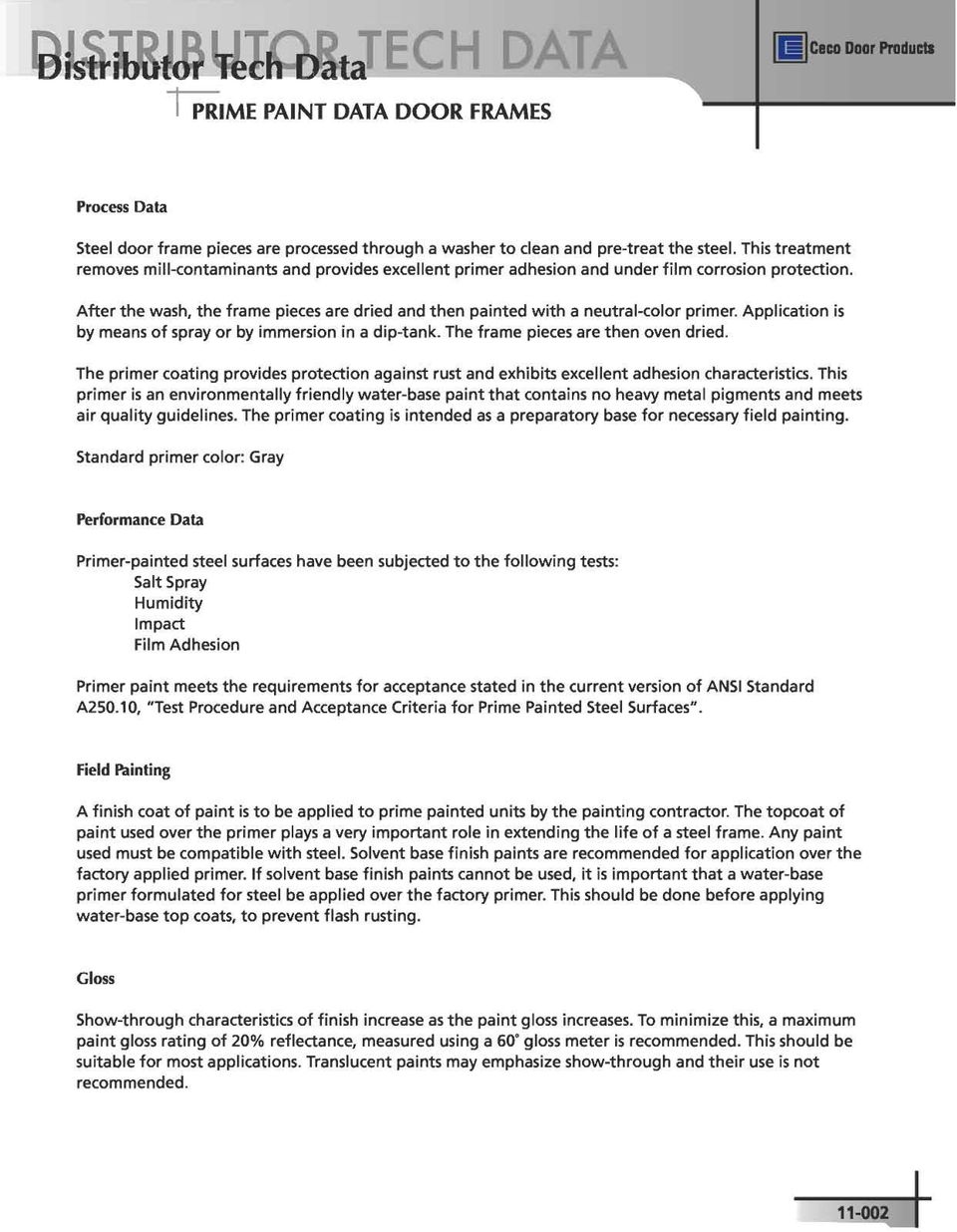
4 Ceco Door Products DISTRIBUTOR TECH DATA Distributor Tech Data COLORSTYLE PAINT DATA DOOR FRAMES Process Data Factory-applied Colorstyle finish is a two-part, urethane top-coat that is electrostatically applied over the standard primer. The paint is then oven cured. The chemically reactive cure provides a top quality, abrasion resistant finish with excellent weathering characteristics. This finish is environmentally friendly in that it does not contain heavy metal pigments. 60 Gardner Gloss: 15 to 20. Colors: Standard color selectors available upon request. Performance Data Colorstyle, factory applied finish paint process has been subjected to the following tests: Salt Spray Humidity Accelerated Weathering Impact Film Adhesion Abrasion Factory applied Colorstyle finish paint meets the performance requirements and acceptance criteria as stated in ANSI Standard A250.3, Test Procedure and Acceptance Criteria for Factory Applied Finish Painted Steel Surfaces

5 NOMINAL SIZES 1-3/8 DOOR FRAME NOMINAL DOOR OPENING WIDTH NOMINAL DOOR OPENING WIDTH NOMINAL DOOR OPENING HEIGHT NOMINAL DOOR OPENING HEIGHT FINISH FLOOR SINGLE FRAME DOUBLE FRAME STANDARD DOOR OPENING SIZES OPENING HEIGHT SINGLE PAIR WIDTH WIDTH FRAMES ON THIS PAGE ARE FOR USE WITH 1-3/8" THICK DOORS

6 Ceco Door Products DISTRIBUTOR TECH DATA Distributor Tech Data 1-3/8 DOOR FRAMES HINGE AND STRIKE LOCATIONS FRAME HEIGHTS * ( " ) 15" 32.93" (32 16 ) 32.93" 15" (31 16 ) 31.93" 15" (31 16 ) 31.93" 9.75" 15" (29 16 ) 29.93" 15" (29 16 ) 29.93" 3" ( 9 ) ( 59 7" ) " HINGE SPACING C L C L C L * Labeled 6-8 frames require 3 hinges. 2 hinges standard for non-labeled 6-8 frames 3 hinges optional for non-labeled 6-8 frames 0.31" STRIKE HEIGHT ( ) 0 5" " ( ) 10 3" 8 C L FRAME HEIGHTS STANDARD FRAME " 3" ( 9 ) C L 26.18" 2.18" ( 19 1" ) " ( " ) HINGE SPACING ( 26 3" 16 ) ( 2 3" 16 ) ( 20 3" 16 ) 20.18" C L C L C L STRIKE HEIGHT 20.18" 10.37" ( 10 3" 8 ) C L 33.62" ( 33 5" 8 ) DUTCH DOOR FRAME
 C L 26.18\" 2.18\" ( 19 1\" ) 2 19.5\" (20 16 3\" ) HINGE SPACING ( 26 3\" 16 ) ( 2 3\" 16 ) ( 20 3\" 16 ) 20.18\" C L C L C L STRIKE HEIGHT 20.18\" 10.37\" ( 10 3\" 8 ) C L 33.")
7 NOMINAL SIZES 1-3/ DOOR FRAME SIZES NOMINAL DOOR OPENING WIDTH NOMINAL DOOR OPENING WIDTH NOMINAL DOOR OPENING HEIGHT NOMINAL DOOR OPENING HEIGHT FINISH FLOOR SINGLE FRAME DOUBLE FRAME STANDARD DOOR OPENING SIZES OPENING HEIGHT SINGLE PAIR WIDTH WIDTH

8 Ceco Door Products DOOR OPENING HEIGHTS DISTRIBUTOR TECH DATA Distributor Tech Data STANDARD HARDWARE LOCATIONS 1-3/ DOOR FRAMES: 6-8, 7-0 & 7-2 HEIGHTS -1/2 OR 5 HIGH HINGES " C L 3" 33" HINGE SPACING 31" C L C L STRIKE HEIGHT 3" 33" 31" 1.81" ( ) 1 13" 16 9" C L These hardware locations are Ceco Door Products standard and will be furnished unless otherwise agreed to
 1 13\" 16 9\" C L These hardware locations are Ceco Door Products standard and will be")
9 NOMINAL SIZES STANDARD HARDWARE LOCATIONS FOR 1-3/ DOOR FRAMES: 7-10, 8-0, 9-0, AND 10-0 HEIGHTS DOOR OPENING HEIGHTS " 3" 25.33" 30" 26" * 21" (25 6 ) C L C L 3" 3" 30" 30" 26" 26" ( 21" *25 ) " ( 21" *25 ) " HINGE SPACING C L C L 1.81" STRIKE HEIGHT ( ) 1 13" 16 C L 9" * 21/6" represents a measurable approximation to.33". These hardware locations are Ceco Door Products standard and will be furnished unless otherwise agreed to A
 1 13\" 16 C L 9\" * 21/6\" represents a measurable approximation to.33\".")
10

11 NOMINAL SIZES FACTORY STANDARD HARDWARE LOCATIONS: HEIGHTS 5-0 THRU 10-0 OPENING HEIGHT NUMBER OF HINGES DIM "A" 5'-0" 2 2" OPENING HEIGHT NUMBER OF HINGES DIM "A" 5'-1" " 5'-2" 3 22" 5'-3" " 5'-" 3 23" 5'-5" " 5'-6" 3 2" 5'-7" 3 2.5" 5'-8" 3 25" 5'-9" " 5'-10" 3 26" 5'-11" " 6'-0" 3 27" 6'-1" " 6'-2" 3 28" 6'-3" " 6'-" 3 29" 6'-5" " 6'-6" 3 30" 6'-7" " 6'-8" 3 31" 6'-9" " 6'-10" 3 32" 6'-11" " 7'-0" 3 33" 7'-1" " 7'-2" 3 3" 7'-3" 3 3.5" 7'-" 3 35" 7'-5" " 7'-6" 3 36" OPENING HEIGHT NUMBER OF HINGES DIM "A" 7'-7" 2.33" 7'-8" 7'-9" 7'-10" 7'-11" 8'-0" 8'-1" 8'-2" 8'-3" 8'-" 8'-5" 8'-6" 8'-7" 8'-8" 8'-9" 8'-10" 8'-11" 9'-0" 9'-1" 9'-2" 9'-3" 9'-" 9'-5" 9'-6" 9'-7" 9'-8" 9'-9" 9'-10" 9'-11" 10'-0" 2.66" 25" 25.33" 25.66" 26" 26.33" 26.66" 27" 27.33" 27.66" 28" 28.33" 28.66" 29" 29.33" 29.66" 30" 30.33" 30.66" 31" 31.33" 31.66" 32" 32.33" 32.66" 33" 33.33" 33.66" 3" 11-10C

12 Ceco Door Products DISTRIBUTOR TECH DATA Distributor Tech Data STANDARD HARDWARE LOCATIONS, 1-3/ DUTCH FRAMES: 6-8, 7-0, 7-2 & 8-0 HEIGHTS - -1/2 OR 5 HIGH HINGES DOOR OPENING HEIGHTS " C L 38.31" 22 5" ( 17 3" 8 ) 17.37" HINGE SPACING 28.31" 26.31" 22.31" ( 38 5" 16 ) 5" ( ) 5" ( ) 22.31" ( 16 ) 5" ( ) LC LC LC 33.62" STRIKE HEIGHT ( 33 5" 8 ) LC 9" These hardware locations are Ceco Door Products standard and will be furnished unless otherwise agreed to D
 LC 9\" These hardware locations are Ceco Door Products standard and will be furnished unless")
13 NOMINAL SIZES NAAMM ALTERNATE HDWE LOCATIONS, 1-3/ DOOR FRAMES: 6-8, 7-0 & 7-2 HEIGHTS -1/2 HIGH HINGES DOOR OPENING HEIGHTS HARDWARE LOCATIONS SHOWN BELOW ARE BASED ON THE FOLLOWING: 5" from head to top of upper hinge. 10" from bottom of jamb to bottom of lower hinge. Equal spacing between intermediate hinges " ( 7 1" ) LC 33.25" 32.25" 30.25" HINGE SPACING 33.25" 32.25" 30.25" ( 33 1" ) ) (32 1" ) (30 1" ) (33 1" ( 32 1" ) ( 30 1" ) LC Strike Height On Frame Is Dependent On Knob Or Crossbar Height. Refer To Door Hardware Locations (p ) And Manufacturer's Lock Template To Determine Relationship Between Lock And Strike " ( 12 1" ) LC The above hardware locations will be furnished only when agreed to
 And Manufacturer's Lock Template To Determine Relationship Between Lock And Strike. 12.")
14 NOMINAL SIZES NAAMM HDWE LOCATIONS, 1-3/ DOOR FRAMES: 7-10, 8-0, 9-0, AND 10-0 HEIGHTS - -1/2 HIGH HINGES DOOR OPENING HEIGHTS HARDWARE LOCATIONS SHOWN BELOW ARE BASED ON THE FOLLOWING: 5" from head to top of upper hinge. 10" from bottom of jamb to bottom of lower hinge. Equal spacing between intermediate hinges ) ( 33 1" 33.5" 2 ) ( 33 1" 33.5" 2 ( 33 1" ) 33.5" 2 29 ) ( 1" 7.25" " 29 ) ( 1" " ( 29 1" ) 29.5" " 2 ) ( ( 25 1" ) 1" ( 7 ) 25.5" 25 1" 2 ) ( 25.5" 25.5" 2 * ) 53" 6 (2 53" 2.83" ( " HINGE SPACING * ) * 53" (2 6 ) 2.83" C L CL C L Strike Height On Frame Is Dependent On Knob Or Crossbar Height. Refer To Door Hardware Locations (p a) And Manufacturer's Lock Template To Determine Relationship Between Lock And Strike " ( 12 1" ) LC * 53/6" represents a measurable approximation to.83". The above hardware locations will be furnished only when agreed to A

15 Ceco Door Products DISTRIBUTOR TECH DATA Distributor Tech Data NAAMM ALTERNATE HDWE LOCATIONS, 1-3/ DOOR FRAMES: 6-8, 7-0 & 7-2 HEIGHTS 5 HIGH HINGES HARDWARE LOCATIONS SHOWN BELOW ARE BASED ON THE FOLLOWING: DOOR OPENING HEIGHTS 5" from head to top of upper hinge. 10" from bottom of jamb to bottom of lower hinge. Equal spacing between intermediate hinges " ( 7 1" 2 ) LC 33" 33" 32" 30" 32" 30" HINGE SPACING LC Strike Height On Frame Is Dependent On Knob Or Crossbar Height. Refer To Door Hardware Locations (p. 01-0) And Manufacturer's Lock Template To Determine Relationship Between Lock And Strike. 12.5" ( 12 1" 2 ) LC The above hardware locations will be furnished only when agreed to
 And Manufacturer's Lock Template To Determine Relationship Between Lock And Strike. 12.")
16 Ceco Door Products DISTRIBUTOR TECH DATA Distributor Tech Data NAAMM ALTERNATE HDWE LOCATIONS 1-3/ DOOR FRAMES: 7-10, 8-0, 9-0 AND 10-0 HEIGHTS - 5 HIGH HINGES HARDWARE LOCATIONS SHOWN BELOW ARE BASED ON THE FOLLOWING: DOOR OPENING HEIGHTS 5" from head to top of upper hinge. 10" from bottom of jamb to bottom of lower hinge. Equal spacing between intermediate hinges " ( 7 1" 2 ) * * * * 21" (33 6 ) 21" (29 6 ) 21" (25 6 ) C L CL C L Strike Height On Frame Is Dependent On Knob Or Crossbar Height. Refer To Door Hardware Locations (p. 01-0a) And Manufacturer's Lock Template To Determine Relationship Between Lock And Strike " 29.33" 21" (2 32 ) 25.33" 2.66" 33.33" * ) ( 33 21" " ) ( 33 21" " * 29 21" ( 6 ) 29.33" 29 21" ( 6 ) 25.33" ) 21" ( " ) 21" ( " ( ) * * * * * * " 32 21" HINGE SPACING ( " ) 12.5" ( 12 1" 2 ) LC * 21/6" represents a measurable approximation to.33". * 21/32" represents a measurable approximation to.66". The above hardware locations will be furnished only when agreed to A
 And Manufacturer's Lock Template To Determine Relationship Between Lock And Strike. 33.33\" 29.33\" 21\" (2 32 ) 25.33\" 2.66\" 33.33\" * ) ( 33 21\" 6 33.33\" ) ( 33 21\" 6 29.33\" * 29 21\" ( 6 ) 29.")
17 NOMINAL SIZES 1-3/8 DOOR FRAME STRIKE AND HINGE PREPS 3/16"(NOM.) BACKSET 1-5/32" 7/32" 16 GAGE STRIKE REINFORCEMENT 16 GAGE FORMED STEEL STRIKE REINF. PROJECTION WELDED (2) PLACES EACH END PIERCE, DRAW AND TAP FOR #8-32 MS TO PROVIDE A MIN. 1/8" THREAD DEPTH 21/6" PLASTER GUARD FORMED AS PART OF STRIKE REINF. 1-17/32" 2-1/8" 2-25/32" 1-1/" (NOM.) 5/16"(NOM.) BACKSET STRIKE REINFORCEMENT USE WITH CYLINDRICAL LOCKS ONLY (1-1/8" x 2-3/" "T" STRIKE) PLASTER GUARD 1-9/16" 1-1/" 21/6" FACE NOTCH VARIES PER FRAME GAGE 26 GAGE STEEL PLASTER GUARD IS SNAPPED-IN PLACE AFTER HINGE REINF. IS WELDED TO JAMB 23/6" 1-25/6" 3-1/2" 8" 1-25/6" 3/8" 21/6" 12 GA. HINGE REINF. PROJECTION WELDED TO FRAME (3) PLACES EACH END 23/6" FACE NOTCH VARIES PER FRAME GAGE 1-9/16" TAPPED HOLES FOR #10-2 MS (3) PLACES HINGE PREPARATION FOR USE WITH 3-1/2" HIGH TEMPLATE HINGES (ANSI A156.7)
 BACKSET STRIKE REINFORCEMENT USE WITH CYLINDRICAL LOCKS ONLY (1-1/8\" x 2-3/\" \"T\" STRIKE) PLASTER GUARD 1-9/16\" 1-1/\" 21/6\" FACE NOTCH VARIES PER FRAME GAGE 26 GAGE STEEL PLASTER GUARD IS SNAPPED-IN")
18 Ceco Door Products DISTRIBUTOR TECH DATA Distributor Tech Data 1-3/ DOOR FRAME -1/2 & 5 HINGE PREPS

19
20 Ceco Door Products DISTRIBUTOR TECH DATA Distributor Tech Data 1-3/ DOOR FRAME CYLINDRICAL STRIKE PREPARATION 3" 8 (NOM.) BACKSET PLASTER GUARD FORMED AS PART OF STRIKE REINFORCEMENT 1 5" 32 CUTOUT 13" GAGE FORMED STEEL STRIKE REINFORCEMENT PROJECTION WELDED (2) PLACES EACH END PIERCE, DRAW AND TAP FOR #8-32 MS TO PROVIDE A MINIMUM 1/8" THREAD DEPTH 21" " " " 32 21" "
 PLACES EACH END PIERCE, DRAW AND TAP FOR #8-32 MS TO")
21 NOMINAL SIZES SERIES SQW WEATHERSTRIP KERF FRAME HINGE PREPARATION 1-5/8" (N0M.) 1/2"(NOM.) BACKSET TAPPED HOLE FOR #12-2 M.S. () PLACES ELEVATED PIPS REMAIN INTACT FOR.13 HINGES BUT MUST BE REMOVED FOR.180 HINGES () PLACES 1-1/" 26 GAGE STEEL PLASTER GUARD IS SNAPPED-IN PLACE. HINGE REINFORCEMENT IS WELDED TO JAMB. PLASTER GUARD 9" 1/2" -1/2" 2 1-1/8" 1-1/" 1-1/8" 1/2" FIT FOAM FILLED WEATHERSTRIP TO FRAME AFTER FINISH PAINTING 2-1/8" FACE NOTCH VARIES PER FRAME GAGE AND HINGE WEIGHT 1-1/" 7 GAGE HINGE REINFORCEMENT PROJECTION WELDED TO FRAME () PLACES EACH END -1/2" HINGE PREP FOR USE WITH -1/2" HIGH TEMPLATE HINGES (ANSI A156.7) 26 GAGE STEEL PLASTER GUARD IS SNAPPED-IN PLACE. HINGE REINFORCEMENT IS WELDED TO JAMB. 1-5/8" (N0M.) 1/2"(NOM.) BACKSET 5/16" 5/8" TAPPED HOLE FOR #12-2 MS () PLACES PLASTER GUARD 1/2" 9" 5" 1-1/" 1-1/2" 7 GAGE HINGE REINFORCEMENT PROJECTION WELDED () PLACES EACH END 1-1/" 2 5/16" 5/8" 1/2" FACE NOTCH VARIES PER FRAME GAGE AND HINGE WEIGHT 2-1/8" 5" HINGE PREP FOR USE WITH 5" HIGH TEMPLATE HINGES (ANSI A156.7)
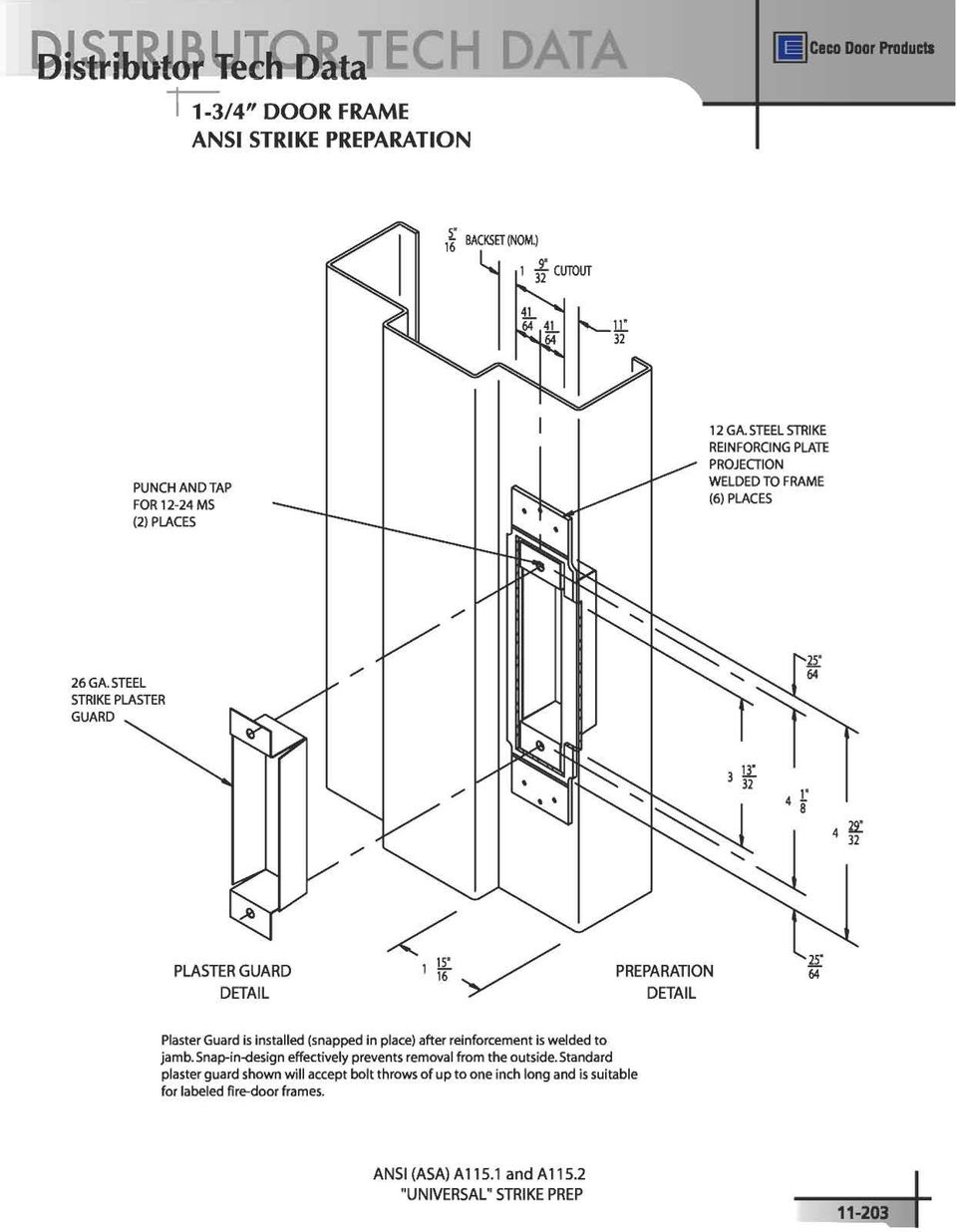
22 Ceco Door Products DISTRIBUTOR TECH DATA Distributor Tech Data SERIES CF PROFILE WK WEATHERSTRIP - KERF FRAME STRIKE PREPARATION 1" 2 BACKSET (NOM.) 1 9" 32 CUTOUT 11" 32 PUNCH AND TAP FOR 12-2 MS (2) PLACES 12 GAGE STEEL STRIKE REINF. PLATE - PROJECTION WELDED TO FRAME (6) PLACES 26 GAGE STEEL SNAP-IN PLASTER GUARD 9" 16 BACKSET (NOM.) 1 5" 32 CUTOUT 13" " " 32 25" 6 1" 8 25" 6 29" GAGE FORMED STEEL STRIKE REINF. PROJECTION WELDED (2) PLACES EACH END PIERCE, DRAW AND TAP FOR #8-32 MS TO PROVIDE A MIN. 1/8" THREAD DEPTH FIT FOAM FILLED WEATHERSTRIP TO FRAME AFTER FINISH PAINTING 1 17" " " 2 25" GAGE STRIKE REINFORCEMENT 1" 2 8 FACE NOTCH VARIES PER FRAME GAGE 21" 6 PLASTER GUARD FORMED AS PART OF STRIKE REINF
23 NOMINAL SIZES 1-3/ DOOR FRAME, FULL DEPTH HINGE REINFORCEMENT FRAME WIDTH LESS 1/2" 5" (NOM) 16 BACKSET 1 5" 8 (NOM.) XX X X 12" XXXX TAPPED HOLE FOR #12-2 MS () PLACES 5" 16 5" 8 1" 2 7 GAGE HINGE REINFORCEMENT WELDED TO FRAME 1" 1 8 1" 2 1 1" 1" 1 8 XXXX 1" 2 XXXX AVAILABLE FOR FRAME DEPTHS 5-1/2" THRU 10-5/8" 1 15" 16-1/2" HIGH HINGE APPLICATION SHOWN
24 Ceco Door Products DISTRIBUTOR TECH DATA Distributor Tech Data DOOR FRAME HIGH FREQUENCY HINGE REINFORCEMENT STRAP 3 " 2" 5/8" STOP 1 8 " 1" 1/" LONG ARC WELDS (3) PLACES PER STRAP STEEL STRAP HINGE REINFORCEMENT AND PLASTER GUARD APPLIED PER PAGE #
25 NOMINAL SIZES DOOR FRAME MUTES SINGLE SWING DOOR FRAMES - 3 MUTES DOUBLE SWING DOOR FRAMES - 2 MUTES DUTCH DOOR FRAMES - MUTES 12" MAX. M 6" ON CENTER M M M 9 3/" MAX. M = MUTE C L OF STRIKE SINGLE SWING M 12" MAX. DOUBLE SWING STANDARD LOCATION OF DOOR MUTES INSERT BLUNT END OF 3/32" DIAMETER WIRE OR TOOL IN HOLE IN CENTER OF MUTE. MOISTEN CONE PORTION AND INSERT IN HOLE IN STOP OF FRAME, PUSHING SLOWLY WITH CIRCULAR MOTION TO ELONGATE MUTE SUFFICIENTLY TO SET IN PLACE. REMOVE WIRE Fed. Spec. Type 1337A DOOR MUTES (SILENCERS) MAINTAIN PROPER SPACE (1/16") BETWEEN DOOR AND FRAME STOP AND CUSHION DOOR CLOSING. INSERT MUTES INTO FRAME BEFORE FRAME IS INSTALLED INTO WALL TO PREVENT GROUT, PLASTER, ETC. FROM FILLING HOLES
26 Ceco Door Products DISTRIBUTOR TECH DATA Distributor Tech Data REVERSIBLE FLUSH BOLT PREPARATION Center of cutout and door Center line of Door Opening Width and Cutout Part A HEAD 15/16" RRA/LA shown Flip flop Part B for LRA/RA Weld Part A to Head at each side Part B Note 1 Pips are provided for projection welding. If other welding is used, flip Part A over. Tackweld Part E on back of reinforcement as necessary. PLASTER GUARD RFB Assembly Parts A,B, and D as listed below: A. (12 ga. galv. steel) Note 1 Tapped for #8-32 MS Part A REINFORCEMENT B. (16 ga. galv. steel, prime paint) C. (16 ga. galv. steel, prime paint) Part B STRIKE D. #8-32 x 1/2" UCFHMS (2) E. Plaster guard (Included on SU and SQ frames only) Part C STRIKE FILLER Part D
27 NOMINAL SIZES DIE-CUT, DOUBLE-RABBET FRAME WELDED CORNER ASSEMBLY Reference: This corner has a full and continuous backbend at the head and jambs. It can be used on frames that cap the wall. STANDARD KD HEAD 1. Assemble frame: Bend tabs after assuring that face-miter seam is "closed" and "tight". Bend corner reinforcement tabs toward inside (toward throat) of frame. Bend rabbet tabs towards outside (toward jamb backbends). 2. Place weld bead as required at the joint of the head and jamb soffits from the backside. 2a. If weld penetration occurs, file smooth. 2b. Spot paint STANDARD KD JAMB Narrow Stop FACE-MITER SEAM IS VISIBLE NARROW STOP (up to 1-1/2" wide) One 1/2" (minimum) length stitch weld, located in the center of the soffit. WIDE STOP (1-1/2" wide and up) Wide Stop: Two 1/2" long stitch welds located at each end of the head and jamb soffit seam. WELDING TYPE T-1 "STITCH WELD at SOFFIT ONLY" Standard KD frame components from stock with corner reinforcements. NO SAWING REQUIRED. WELDING TYPE T
28 Ceco Door Products DISTRIBUTOR TECH DATA Distributor Tech Data DIE-CUT, DOUBLE-RABBET FRAME WELDED CORNER ASSEMBLY 1. Assemble frame: Bend tabs after assuring that face-miter seam is "closed" and "tight" Bend corner reinforcement tabs toward inside (toward throat) of frame. Bend rabbet tabs toward outside(toward jamb backbends) of frame. 2. Weld the entire face-miter seam, between head and jamb, from the outside (both faces). 3. Grind and dress smooth both face-miter seams after welding. 3a. Spot paint STANDARD KD HEAD 2 FACE-MITER SEAM IS COMPLETELY INVISBLE STANDARD KD JAMB T-2 WELDING TYPE T-2 "OUTSIDE FACE WELD ONLY" Standard KD frame components from stock with corner reinforcements. NO SAW CUTTING REQUIRED. Reference: This corner has a full and continuous backbend at the head and jambs. It can be used on frames that cap the wall. STANDARD KD HEAD Reference: This corner has a full and continuous backbend at the head and jambs. It can be used on frames that cap the wall. 1. Assemble frame: Bend tabs after assuring that face-miter seam is "closed" and "tight" Bend corner reinforcement tabs toward inside (toward throat) of frame. Bend rabbet tabs toward outside(toward jamb backbends) of frame. 2. Weld the entire face-miter seam, between head and jamb, from the outside (Both faces). STANDARD KD JAMB 3. Grind an dress smooth both face-miter seams after welding. FACE-MITER SEAM IS COMPLETELY INVISIBLE. Weld the entire web seam (including the seams between head and jamb rabbets, stops and soffits) from the backside, with a continuous weld bead. a. If weld penetration occurs, file smooth. T-3 5. Spot paint WELDING TYPE T-2 "OUTSIDE FACE WELD and FULL WEB WELD" Standard KD frame components from stock with corner reinforcements. NO SAW CUTTING REQUIRED
29 NOMINAL SIZES DIE-CUT, DOUBLE-RABBET FRAME WELDED CORNER ASSEMBLY Reference: This corner has a full and continuous backbend at the head and jambs. It can be used on frames that cap the wall. rabbet tabs toward outside (toward jamb backbends) face-miter seam is "closed" and "tight". Bend 1. Assemble frame: Bend tabs after assuring that of frame. DIE-CUT HEAD 2. Weld the entire face-miter seam from the inside. Weld is to penetrate to exterior. 2a. Grind the exterior face and fill as necessary. FACE-MITER SEAM IS COMPLETELY INVISIBLE DIE-CUT JAMB V-2 WELDING TYPE V-2 " INSIDE FACE WELD ONLY" Die-cut frame components - VOID OF CORNER REINFORCEMENTS NO SAW CUTTING REQUIRED
30 Ceco Door Products DISTRIBUTOR TECH DATA Distributor Tech Data DIE-CUT, DOUBLE RABBET FRAME WELDED CORNER ASSEMBLY 1. Assemble frame: Bend tabs after assuring that face-miter seam is "closed" and tight. Bend rabbet tabs toward outside (toward jamb backbends) of frame. 2. Weld the entire face-miter seam from the inside. Weld is to penetrate to exterior. 2a. Grind the exterior face and fill as necessary. FACE-MITER SEAM IS COMPLETELY INVISIBLE Reference: This corner has a full and continuous backbend at the head and jambs. It can be used on frames that cap the wall. 3. Dress reworked areas.. Weld the entire web seam (including the seams between head and jamb rabbets, stops, and soffits) from the backside with a continuous weld bead. a. If weld penetration occurs, file smooth. 5. Spot weld. 2 DIE-CUT HEAD V-3 WELDING TYPE V-3 "INSIDE FACE WELD and FULL WEB WELD" Die-cut frame components - VOID OF CORNER REINFORCEMENTS NO SAW CUTTING REQUIRED. DIE-CUT JAMB 11-30
31 1a. Clamp the head and jamb at 90.
32 2. Clamp head and jamb at 90.
33 frame sections is 90.
34 Ceco Door Products DISTRIBUTOR TECH DATA Distributor Tech Data & 6 HOSTPITAL STOPS
35 NOMINAL SIZES CLOSER REINFORCEMENT PLATE TYPE REINFORCEMENT PLATE: 1 GAGE MIN. STEEL x 1/3/" x 1" (1) Note: If 1-3/" dimension is too big to fit face...decrease size to suit. REINFORCEMENT PLATE: 1 GAGE MIN. STEEL x 1/3/" x 1" (1) Note: If 1-3/" dimension is too big to fit stop..decrease size to suit. PLACE FLAT AGAINST INSIDE OF FACE AND " 1" BUTT AGAINST INSIDE 2" 1" OF DOOR RABBET. HEAD HEAD PLACE FLAT AGAINST INSIDE OF DOOR SOFFIT AND BUTT AGAINST INSIDE OF DOOR STOP (1) 1" LONG (APPROX) STITCH WELD AT EACH END OF PLATE DOOR RABBET (1) 1" LONG (APPROX) STITCH WELD AT EACH END OF PLATE DOOR RABBET LOCATION OF OPTIONAL PLATE, SEE HINGE JAMB HINGE JAMB Note: Verify against manufacturer's template that size and position of plate satisfy hardware needs. REGULAR ARM CLOSER MOUNTING PARALLEL ARM CLOSER MOUNTING REINFORCEMENT PLATE: 1 GAGE MIN. STEEL x 1/3/" x 1" (2) Note: If 1-3/" dimension is too big to fit stop...decrease size to suit. REINFORCEMENT PLATE: 1 GAGE MIN. STEEL x 1/3/" x 1" (1) Note: If 1-3/" dimension is too big to fit face...decrease size to suit. 1" HEAD PLACE FLAT AGAINST INSIDE OF DOOR SOFFIT AND BUTT AGAINST INSIDE OF DOOR STOP 2" 1" HEAD PLACE FLAT AGAINST INSIDE OF FACE AND BUTT AGAINST INSIDE OF HEAD BACKBEND. 1" (1) 1" LONG (APPROX) STITCH WELD AT EACH END OF EACH PLATE (1) 1" LONG (APPROX) DOOR STITCH WELD AT EACH RABBET END OF PLATE HINGE JAMB Note: Do not use with standard DW plumb anchor. Not recommended when door opening height is less than 7'-'0". DOOR RABBET STOP HINGE JAMB CORNER BRACKET CLOSER MOUNTING TOP JAMB CLOSER MOUNTING 11-01
36 Ceco Door Products DISTRIBUTOR TECH DATA Distributor Tech Data CLOSER REINFORCEMENT PLATE TYPE REINFORCEMENT PLATE: 1 GAGE MIN. STEEL x 1/3/" x 1" (1) Note: If 1-3/" dimension is too big to fit face..decrease size to suit. REINFORCEMENT PLATE: 1 GAGE MIN. STEEL x 1/3/" x 1" (1) Note: If 1-3/" dimension is too big to fit stop..decrease size to suit. PLACE FLAT AGAINST IN- SIDE OF RABBET OPPOSITE 2" 1" DOOR AND BUTT AGAINST 7" INSIDE OF DOOR FACE HEAD 1" HEAD PLACE FLAT AGAINST INSIDE OF DOOR SOFFIT AND BUTT AGAINST INSIDE OF DOOR STOP (1) 1" LONG (APPROX) STITCH WELD AT EACH END OF PLATE DOOR RABBET LOCATION OF OPTIONAL PLATE, SEE (1) 1" LONG (APPROX) STITCH WELD AT EACH END OF PLATE CL of opening DOOR RABBET HINGE JAMB Note: Verify against manufacturer's template that size and position of plate satisfy hardware needs. PARALLEL ARM CLOSER MOUNTING Note: Verify against manufacturer's template that size and position of plate satisfy hardware needs. OUTSWING DOOR: SURFACE BOLTS AND REMOVABLE MULLIONS REINFORCEMENT PLATE: 1 GAGE MIN. STEEL x 1/3/" x 1" (1) REINFORCEMENT PLATE: 1 GAGE MIN. STEEL x 1/3/" x 1" (1) Note: If 1-3/" dimension is too big to fit face..decrease size to suit. 7" 1" HEAD PLACE FLAT AGAINST INSIDE OF FACE AND BUTT AGAINST INSIDE OF DOOR RABBET Note: If 1-3/" dimension is too big to fit stop..decrease size to suit. PLACE FLAT AGAINST INSIDE OF DOOR SOFFIT AND BUTT AGAINST INSIDE OF DOOR STOP 1" DOOR RABBET 7" cl (1) 1" LONG (APPROX) STITCH WELD AT EACH END OF PLATE DOOR RABBET (1) 1" LONG (APPROX) STITCH WELD AT EACH END OF PLATE CL of opening Note: Verify against manufacturer's template that size and position of plate satisfy hardware needs. 33-5/16" 0-5/16" INSWING DOOR: SURFACE BOLTS RIM TYPE PANIC DEVICE MOUNTING BOTTOM OF STRIKE JAMB 11-02
37 NOMINAL SIZES HALF-CLOSER REINFORCEMENT " 13-7/8" HEAD CR/HALF DOOR SIDE 1GA. GALV. STL. 1-5/8" 13-7/8" 1-31/32" 5/8" HINGE JAMB REGULAR & PARALLEL ARM CLOSER MOUNTING 1-1/2" SPOT OR TACK WELDED IN PLACE. (2) WELDS PER END 2" MIN. FACE FRAME HEAD SECTION 1-15/16" RABBET 11-03
38 NOMINAL SIZES JAMB ANCHOR QUANTITIES FOR STANDARD HEIGHT FRAMES ANCHOR TYPE QUANTITY JAMB ANCHORS PER FRAME 6-8 THRU THRU 10-0 FLOOR ANCHORS PER FRAME NEW MASONRY EXISTING OPENING 8 10 OMIT WOOD STUD * METAL STUD * SOLID PLASTER * LAMINATED DRYWALL * * Floor anchors may be omitted and replaced with two additional jamb anchors. Unless otherwise indicated, jamb anchors are normally located on the same center line as the hinge preparations except where interference would occur with hardware reinforcements. Where interference would occur, anchors should be positioned above or below hinge reinforcements and directly opposite on the strike jamb. For sizes other than listed above, the following guidelines are followed (unless otherwise indicated)...for heights to 6-0: Two jamb anchors per jamb; For heights greater than 6-0 thru 7-6: Three jamb anchors per jamb; For heights greater than 7-6 thru 10-0: Four jamb anchors per jamb; and for each additional 2 feet of height or fraction thereof: One additional jamb anchor per jamb
39 NOMINAL SIZES WELDED FLOOR ANCHOR WELD 11/16 11/16 CENTER OF JAMB AND ANCHOR WELD TWO PIECE APPLICATION ONE PIECE APPLICATION 3-1/8 1-1/2 5/16 DIA. HOLES 1-1/2 1-7/16 5/16 DIA. HOLES 1/2 1/2 1" CTC SPACES 1-23/32 1/2 1/2 DIM A 16 GAGE GALV STEEL TWO PIECE ANCHOR (16 GA. GALV.) (16 GA. COLD ROLLED) ONE PIECE ANCHOR SELECTION CHART DIM A FRAME DEPTH HOLES 3-1/ /2 8-1/2 to 5-1/ 5-3/8 to 6-3/ 6-7/8 to 8-1/ 8-3/ to 9-3/ All dimensions are in inches. For SI conversion: 1" = 25. mm. Anchors for depths outside the above range are made to order
40 Ceco Door Products DISTRIBUTOR TECH DATA Distributor Tech Data ADJUSTABLE FLOOR ANCHOR " TRAVEL HAT: -1/" WIDE x 3/" LEGS x 5/8" 3-1/" LONG 2-1/8" ANGLE: 1-1/2" x 2-3/" LONG SCREW: #10 x 3/" THSMS FLUSH WITH JAMB BOTTOM 5/16" DIA. 2-1/8" O.A
41 NOMINAL SIZES SIDELITE FLOOR ANCHOR Note: Anchor is attached to floor at two places. Mullion or sill is slipped over anchor (fastening is optional). IMPOST IMPOST FOR VERTICAL MULLIONS FLOOR 12 GAGE STEEL (2) 9/32" DIA. HOLES Dim A Dim A = Depth (-) 3/16" FOR BASE SILLS FLOOR Dim A SILL BRACING STRAP Note: Position sill anchor to avoid possible interference with sill bracing strap if present. Dim A = Depth (-) 1-3/16" (assuming 1/2" backbends)
42 Ceco Door Products DISTRIBUTOR TECH DATA Distributor Tech Data ANCHORS FOR NEW MASONRY 7 GAGE GALV. STEEL WIRE THROAT RANGE 2 THRU 8-3/ R 1-1/" 8" WIRE MASONRY ANCHOR 1 MFG DEPTH FIELD MODIFIED DEPTH " 5-3/ 5-1/ -3/ -1/ 3-3/ 3-3/ / 3-3/ 2-5/16" 9-3/8" SPOTWELDED All dimensions are in inches; for SI conversion, 1" = 25. mm. 16 GAGE GALV STEEL 2" DEPTH 6-3/ 7-3/ 8-1/" 8-3/ MASONRY "T" ANCHOR 1-13/16" 11-50
43 NOMINAL SIZES MASONRY ANCHORS CONT. EXISTING OPENING ANCHOR WELDED Available on special order only FOR ALL FRAME DEPTHS YOKE AND STRAP MASONRY ANCHOR Available on special order only EXISTING OPENING ANCHOR
44 Ceco Door Products DISTRIBUTOR TECH DATA Distributor Tech Data EXISTING OPENING STANDARD JAMB ANCHOR
45 NOMINAL SIZES EXISTING OPENING ANCHOR FOR SPECIAL FACES 1-1/ 1 1/ / 1-1/2 DIM A EXISTING OPENING/NARROW EXISTING OPENING/NARROW ANCHOR SIZE CHART FACE 1 1-1/ 1-1/2 1-3/ 2 2-1/2 DIM A 1-9/ /16 2-1/16 2-5/16 2-9/16 3-1/16 All dimensions are in inches. For SI conversion: 1" = 25.mm. Dimension A assumes a 5/8 frame stop height. Suggested Rough-opening clearance: head and jambs. See page for jamb punching, spacing, fastener, and floor anchor notes
46 Ceco Door Products DISTRIBUTOR TECH DATA Distributor Tech Data WELDED WOOD STUD ANCHOR The wood stud anchor depicted below is shop attached. Unless otherwise designated, a stud anchor will be attached at each sill in lieu of a floor anchor. MSZ1 ANCHOR SPOT WELDED TO JAMB 5/32 DIA. HOLES (2) PLACES EACH STRAP STRAP ANCHOR SPOT WELDED TO MSZ1 ANCHOR 18 GAGE STEEL PORTION OF JAMB REMOVED FOR CLARITY *DIM "X" JAMB * Or to suit other stud sizes. For stud sizes other than shown below: actual stud dimension should be noted. Also, wall board thicknesses should be shown so that straps can be properly positioned. TO SUIT WALL Straps are nailed to stud by contractor 3/16 5/8 JAMB DEPTH EQUALS WALL THICKNESS PLUS 1-1/8 WOOD STUD ANCHOR SELECTION CHART STUD SIZE 2 x 2 x 6 DIM "X" 3-1/2 5-1/2 Wood blocking by contractor as necessary. WALL SECTION INSTALLATION SEQUENCE 1. WALL FRAMING 2. DOOR FRAME 3. WALL SURFACE MATERIAL All dimensions are in inches, for SI conversion, 1" = 25. mm
47 NOMINAL SIZES ADJUSTABLE JAMB ANCHOR FOR STUD WALLS FRAME ANCHOR NAILS OR SCREWS WALL STUD Wood stud shown Metal stud similar HOLLOW METAL FRAME WALL BOARD TYPICAL APPLICATION ASSEMBLY DETAIL (END VIEW) 5 6 Anchors are adjustable in 1/8" increments within given ranges. FRAME DEPTH: 3-3/" thru 6-1/" FRAME DEPTH: 6-1/" thru 8-3/"
48 Ceco Door Products DISTRIBUTOR TECH DATA Distributor Tech Data WELDED METAL STUD ANCHOR RECESSED TYPE The metal stud anchor depicted below is shop attached. Unless otherwise designated, a stud anchor will be provided for each sill. ZEE ANCHOR Dim "A" long) SPOT WELDED TO JAMB 18 GAGE STEEL For single rabbet depths over inches, a 3/ x 5/8 x 3/ x 1 long steel "zee" clip is welded to MSZ anchor and stop as necessary EQUAL EQUAL DIM "A" JAMB Stud is screwed to anchor 5/8 If second stud is used, attach it after jamb is fastened. DIM FRAME "A" DEPTH RANGE 3-1/2-1/2 THRU 5-1/ 5 5-3/8 THRU 6-3/ 6-1/2 6-7/8 THRU 8-1/ 8 8-3/8 THRU 9-3/ WALL SECTION INSTALLATION SEQUENCE 1. DOOR FRAME 2. WALL FRAMING 3. WALL SURFACE MATERIAL All dimensions are in inches, for SI conversion, 1" = 25. mm
49 NOMINAL SIZES WELDED METAL STUD ANCHOR FLUSH TYPE The metal stud anchor depicted below is shop attached. at sill. Designate if floor anchor or jamb anchor is desired 16 GAGE STEEL DIM "B" DIM "A" DIM "C" For single rabbet depths over inches, a 3/ x 5/8 x 3/ x 1 long steel "zee" clip is welded to MSZ anchor and stop as necessary DIM "B" DIM DIM "A" "B" -5/8 13/16 5-7/8 1-7/16 7-1/2 2-1/8 DIM FRAME "C" DEPTH RANGE 3 5-3/8 THRU /8 THRU 7-5/8 3-1/ 7-3/ THRU 9-1/ Stud is screwed to anchor Allow 3/16" clearance between stud and jamb Shim Anchor is normally positioned in the center of throat to accommodate equal thicknesses of wallboard at each side of stud. If wall is not symmetrical, drawings showing condition should be provided. INSTALLATION SEQUENCE If second stud is used, attach it after jamb is fastened. 1. WALL FRAMING 2. DOOR FRAME 3. WALL SURFACE MATERIAL Series BQ should be considered All dimensions are in inches, for SI conversion, 1" = 25. mm
50 Ceco Door Products DISTRIBUTOR TECH DATA Distributor Tech Data BEFOR DRYWALL STUD ANCHOR AND CLOSURE CLIP FOR 2" FACE 1-1/16 C L BEND HERE FOR ONE LAYER OF 1/2" > 5/8" WALLBOARD BEND HERE FOR TWO LAYERS OF 1/2" > 5/8" WALLBOARD TAP-IN PLACE C L 3/ 18 GAGE GALV STEEL 5-5/8 9/16 BEND STUD SIZE 2 FACE NOTE FRAME IS SET-UP AND JAMBS ANCHORED BEFORE WALLBOARD IS INSTALLED. STUD ANCHORS ARE BENT IN FIELD TO THICKNESS OF WALLBOARD. IF WALL FRAME WORK IS SET UP BEFORE DOOR FRAME, USE AN ADDITIONAL JAMB ANCHOR AT SILL INSTEAD OF SILL ANCHOR. BEFORE DRYWALL STUD ANCHOR All dimensions are in inches, for SI conversion, 1" = 25. mm. 1-5/16 3/ 7/32 R. WELD TO JAMB Contractor snaps closure into place after frame is installed. JAMB 16 GAGE STEEL SILL CLIP AT EACH END AND 2" O.C. 1/2" BACKBENDS CLOSURE CLIP
51 NOMINAL SIZES FRAME SPLINES Frame components should have open ends. Mitered corners prevent spline installation without modification of backbend. Allot one spline for every 2 feet of impost height. Drive spline in from ends, locate approx. equal distance from one another. Stitchweld 8" 16 Ga. steel 1" 3/32" DEPTH REWORK FSPA 3-7/8" or OVER 33 SPLINE APPLICATION -3/" or OVER 3 5-3/" or OVER /" or OVER 63 For shipping via common carrier, frame size should not exceed 8'-0" in more than one dimension. SPLINE APPLICATION (For Custom Depths)
52 NOMINAL SIZES FRAME INSTALLATION MASONRY AND STUD WALLS JOBSITE STORAGE: Store frames off the ground on wood runners or skids. Do not store directly on the ground. Cover frames with tarpaulin or plastic but do insure that adequate ventilation is provided to eliminate moisture condensation. When frames are to be fully grouted and when plaster or mortar contain "anti-freeze" agents, the inside of the frames should be coated with a bituminous, water-resistant paint by the installation contractor. ASSEMBLY of FRAME SLOTS FOR CORNER TABS HEAD CORNER TABS JAMB BEND CORNER TABS TOWARD INSIDE OF FRAME CORNER ASSEMBLY SLOTS FOR JAMB TABS JAMB TABS Install rubber silencers before frame is setup to avoid grout plugging holes. BEND JAMB TABS TOWARD OUTSIDE OF FRAME PLUMBING FRAME FRAME DEPTH DOOR OPG AT HEAD SQUARING THE FRAME The installer should use wood spreaders (as described at right), a carpenters level (the longer the better), and a carpenters square (the bigger the better). Set the frame in the desired location. Level head and plumb jambs. Shim under jambs if necessary. SPREADER Typical wood spreader must be square and made from lumber at least 1" thick. Length of spreader equals door opening width at the head. Cut clearance notches for frame stops as shown. Spreader must be nearly as wide as frame depth for proper installation
53 90
54 NOMINAL SIZES X X X X FRAME SPREADER BARS 1. SPREADER BAR PROFILE 2. SPREADER BAR LENGTH Length of spreader bar is equivalent to door opening width dimension. This bar is not to be used for installation. A wood spreader is to be used for maintaining proper spacing between jambs. (See the DHI publication "The Installation of Commercial Steel Doors and Steel Frames", "Insulated Steel Doors in Wood Frames", and "Builder's Hardware"). DOOR RABBET 3. SPREADER BAR QUANTITY AND LOCATION A. All single rabbet frames and double rabbet, single swing frames with depth not exceeding 6 inches: attach (1) spreader bar to the door rabbet. (See Fig. #1) SPREADER B. All double rabbet, double swing frames or double rabbet, single swing frames with depth exceeding 6 inches: attach one (1) spreader bar to each frame rabbet (two total). (see Fig. #2) Fig. #1 X X X X X JAMB. SPREADER BAR ATTACHMENT Verify spreader bar length by checking to see that said length is equivalent to the door opening width dimension at head. Place the spreader bar at the bottom of the door opening and tack weld in place. Strength of welds should be such that spreader bar remains in place during transit and also be such that the spreader bar can be removed when required (by means of a sharp hammer blow) without incurring frame damage. JAMB SPREADERS Fig. #2 X X X X BOTH RABBETS
K. D. FRAME ASSEMBLY FOR CLOSED STEEL STUD WALLS...Ins 10. FRAME INSTALLATION DETAILS FOR CLOSED STEEL STUD WALLS...Ins 11
 K. D. FRAME ASSEMBLY FOR MASONRY WALLS...........................Ins 2 FRAME INSTALLATION DETAILS FOR MASONRY WALLS......................Ins 3 INSTALLING EXISTING MASONRY WALL ANCHORS IN FRAME..................Ins
FRAME PROFILE MASONRY METAL DOOR FRAME FLUSH MASONRY KD MITER CORNER JOINT. #8 Screw (MS002485) Required on all fire rated KD frames. Bend Tabs.
 Required on all fire rated KD frames. Bend Tabs.") FRAME PROFILE MASONRY FLUSH MASONRY KD MITER CORNER JOINT Bend Tabs Head #8 Screw (MS002485) Required on all fire rated KD frames Corner Assembly 2" (50.8) Head Jamb Head Break Away Corner Clip Spot Welds
FRAME PROFILE MASONRY FLUSH MASONRY KD MITER CORNER JOINT Bend Tabs Head #8 Screw (MS002485) Required on all fire rated KD frames Corner Assembly 2" (50.8) Head Jamb Head Break Away Corner Clip Spot Welds
INSTALLATION INSTRUCTIONS
 door frames Engineered product systems INSTALLATION INSTRUCTIONS door frames MINIMALIST DOOR FRAME Fry Reglet Flush Door frames are designed for use with 3 5/8 studs with ½ drywall both sides (4 5/8 throat
WHI 90-Minute Rated Veneered Door Frame Installation Instructions
 No. 940-03-10 INSTALLATION INSTRUCTIONS 90 MINUTE RATED VENEERED DOOR FRAME DOOR REQUIREMENTS: Consult the door manufacturer to make sure that the doors are qualified for the hardware to be installed,
DE Frame with C Series Sidelight
 TOOLS REQUIRED Tape measure 6' magnetic level 3' magnetic level Screw gun with clutch adjusted #2 phillips tip #3 phillips tip Screwdriver (used to adjust frame on will using oval slots) Pry Bar Powder
BASIC FIRE DOOR REQUIREMENTS TECHNICAL DATA SHEET NO. 401
 BASIC FIRE DOOR REQUIREMENTS SHEET NO. 401 Fire door openings are classified by their locations in the building. The location determines the length of exposure protection required, based on the potential
Technical Data Honeycomb Door Leaf 8-1-99
 8--99 8-/8 8-7/8 B 8-/4 A A Dim. A Leaf Width B ELEVATION F DESIGN Vertical edge seams mechanically interlocked Square hinge and lock edges 4-/ x.4 full mortise hinge prep Gov. 60/6 cyl lock prep...prefix
REDI-EXIT COMMERCIAL FIRE DOOR AND EXTERIOR DOOR KITS INSTALLATION GUIDELINES
 REDI-EXIT COMMERCIAL FIRE DOOR AND EXTERIOR DOOR KITS INSTALLATION GUIDELINES Tools Required Tape Measure Hammer Slotted Screw Driver #2 & #3 Philips Screw Driver 3-4 Foot Level 12 Pry Bar Cold Chisel
DIVISION 8, METAL SOUND CONTROL DOOR ASSEMBLIES PART 1 GENERAL 1.1 RELATED DOCUMENTS
 DIVISION 8, METAL SOUND CONTROL DOOR ASSEMBLIES PART 1 GENERAL 1.1 RELATED DOCUMENTS Drawings and general provisions of the contract, including general and supplementary conditions and other Division 1
Brick Veneer Construction
 Brick Veneer Construction Check list of suggested tools & support items Claw hammer Tape measure 3/4" [19 or 20] Wood chisel Wood or plastic shims Pry bar Utility knife Caulking and caulking gun Power
n Three 4 x 4 butt hinges per door - prevents wracking and assures smooth positive operation n Heavy duty 16 gauge steel frame
 Weather Fin and bulb help keep bad weather outside and good air inside Windows: n Many light kits are available 1-LU 4 X 48 1-LE 16 X 16 1-LA 20 X 24 1-LI 20 X 24 1-B 22 X 36 1-LW 16 X 16 W/GRID 9-LB 22
Steel Door Frame Installation in Steel Stud Construction
 Steel Door Frame Installation in Steel Stud Construction For use with the Steel Door Institute (SDI) video How to Install a Steel Door Frames in Steel Stud Construction This manual gives you step-by-step
Wood Sound Retardant Door Hardware Information Bulletin
 overly overly 574 West Otterman Street Greensburg, PA 15601 Toll Free: (800) 979-7300 Local: (724) 834-7300 Fax: (724) 830-2871 Email: overly@overly.com DOOR COMPANY Wood Sound Retardant Door Hardware
Doors and frames. Technical data manual 2015 rev. 8/17/15
 Doors and frames Technical data manual 2015 rev. 8/17/15 Technical data manual Main table of contents NAVIGATE VIA: A) Rollover links in each TOC (each item below is a link), B) Bookmarks on the left,
PANELIZED HOME INSTALLATION GUIDELINE
 PANELIZED HOME INSTALLATION GUIDELINE A typical home package will be constructed of Snap-N-Lock Insulated Panels clad with steel skins. 4" panels will be used for the walls, and 6" panels for the roof.
WINDOW PANNING AND TRIMS
 OCTOBER, 2010 PANNING AND TRIMS GENERAL INFORMATION 1 EXTERIOR PANNING Panning is primarily used to cover the perimeters of existing building openings prior to the installation of replacement windows.
March 14, 2007. Installation of Bay, Bow and Garden Windows
 March 14, 2007 Re: Installation of Bay, Bow and Garden Windows Attached are the Atrium Companies, Inc recommendation for the installation of bay, bow and garden windows. These instructions were developed
Installation S D I 122-99 TECHNICAL DATA SERIES. and Troubleshooting Guide. for Standard Steel Doors and Frames STEEL DOOR INSTITUTE
 TECHNICAL DATA SERIES S D I 122-99 Installation and Troubleshooting Guide for Standard Steel Doors and Frames STEEL DOOR INSTITUTE 30200 DETROIT ROAD - CLEVELAND, OHIO 44145 Table of Contents Improper
Guidelines for Earthquake Bracing of Residential Water Heaters
 Guidelines for Earthquake Bracing of Residential Water Heaters Department of General Services Division of the State Architect 1102 Q Street, Suite 5100 Sacramento, CA 95814 Phone: (916) 324-7099 Fax: (916)
PART 1 GENERAL 1.1 SECTION INCLUDES
 J-1 Section 09110 Long Form Specification INTERIOR METAL STUD FRAMING This section includes lightweight, usually 0.036 inch (0.9 mm) thick or lighter, non-axial load bearing metal stud framing including
INSTALLATION OF A BAY WINDOW
 INSTALLATION OF A BAY WINDOW Installation of a Bay Window These instructions relate to the replacement of an existing bay window or replacement of a straight window with a new bay window, in an opening
HMMA 830 HARDWARE SELECTION FOR HOLLOW METAL DOORS AND FRAMES HOLLOW METAL MANUAL -02 NAAMM STANDARD METAL DOORS & FRAMES NAAMM 01 NAAMM 01
 HOLLOW METAL MANUAL NAAMM STANDARD HMMA 830-02 METAL S & FRAMES 8d NAAMM 01 02 HARDWARE SELECTION FOR HOLLOW METAL S AND FRAMES NAAMM 01 02 8d METAL S & FRAMES A Division of HOLLOW METAL MANUFACTURERS
We urge you to read and follow the attached installation instructions. Failure to do so may void the warranty of this garden window unit.
 Important Information for New Construction Installations Attention Installer! We urge you to read and follow the attached installation instructions. Failure to do so may void the warranty of this garden
DOORS HOLLOW METAL MANUAL NAAMM STANDARD NAAMM HMMA 810-09 METAL DOORS & FRAMES METAL. A Division of
 HOLLOW METAL MANUAL NAAMM STANDARD HMMA 810-09 8d NAAMM HMMA 810-09 METAL DOORS & FRAMES HOLLOW METAL DOORS 8d NAAMM HMMA 810-09 METAL DOORS & FRAMES A Division of HOLLOW METAL MANUFACTURERS A S S O C
Installation Instructions and Ordering Information
 The Flush Finish Trimless Door Frame Installation Instructions and Ordering Information CLEAN LINES! The Flush Finish Door Jamb System Manufactured by STUDCO Building Systems Step 1 Verify if you are using
DOOR COMPONENTS, INC Technical Data
 DOOR COMPONENTS, INC Technical Data DOOR COMPONENTS, INC 7980 Redwood Ave Fontana, CA 92336 Phone (909) 770 5700 Toll Free (866) 989 3667 Fax (909) 770 5722 www.doorcomponents.com INDEX FRAMES: PAGE #
Nomenclature for: Standard Steel Doors and Frames
 ANSI/SDI A250.7-1997 (R2002) Revision and Redesignation of ANSI/SDI A123.1-1989 Nomenclature for: Standard Steel Doors and Frames ANSI/SDI A250.7-1997 STEEL DOOR INSTITUTE SPONSOR Steel Door Institute
HMMA 810 HOLLOW METAL DOORS HOLLOW METAL MANUAL -87 NAAMM STANDARD FOURTH EDITION METAL DOORS & FRAMES NAAMM 2 NAAMM 2 METAL DOORS & FRAMES
 HOLLOW METAL MANUAL NAAMM STANDARD HMMA 810-87 8d METAL DOORS & FRAMES NAAMM 2 87 HOLLOW METAL HOLLOW METAL DOORS FOURTH EDITION NAAMM 2 87 8d METAL DOORS & FRAMES A Division of NATIONAL ASSOCIATION OF
Clad Direct Glaze Window Installation Instructions
 Clad Direct Glaze Window Installation Instructions Sill flashing and sealing: 2. An overview of the proper flashing sequence is shown in figure 1. Please read entire installation instructions carefully
We urge you to read and follow the attached installation instructions. Failure to do so may void the warranty of this garden window unit.
 Important Information for New Construction Installations Attention Installer! We urge you to read and follow the attached installation instructions. Failure to do so may void the warranty of this garden
AMERICAN GOTHIC PLAYHOUSE
 AMERICAN GOTHIC PLAYHOUSE Project Plan #856 Sheet 1 of 5 Pick a spot and get started with the beautiful that your kids will love. The design of the playhouse includes 35 square feet of interior space plus
Guidelines for Earthquake Bracing Residential Water Heaters
 Guidelines for Earthquake Bracing Residential Water Heaters Department of General Services Division of the State Architect In accordance with the Health and Safety Code Section 19215, the Division of the
Ceiling Mounted Folding Attic Ladders Installation Instructions
 Ceiling Mounted Folding Attic Ladders Installation Instructions WARNING Before you start installing your new Louisville Ceiling Mounted Folding Attic Ladder, you must read and understand the following:
Window Installation Instructions
 Caution The correct installation methods of windows in full frame or insert applications is critical towards achieving the tested performance of the window and longterm enjoyment and energy savings for
INSTALLATION INSTRUCTIONS for Bifold Doors (JII103)
") Thank you for selecting JELD-WEN products. Attached are JELD-WEN s recommended installation instructions for premium composite, hollow and solid core molded Bifold Doors. Bifolds are designed for fast
Thank you for selecting JELD-WEN products. Attached are JELD-WEN s recommended installation instructions for premium composite, hollow and solid core molded Bifold Doors. Bifolds are designed for fast
SECTION 6. Glass Storefront Doors:
 SECTION 6 Glass Storefront Doors: Table of Contents 3070 Storefront Door System Description & Dimensions 6070 Storefront Door System Description & Dimensions Door Leaf Detail Optional 10 Bottom Rail Detail
Installing Window and Door Mouldings
 Installing Window and Door Mouldings About Window and Door Mouldings The trim around windows and doors greatly influences the look and style of your interior. They also bridge the gaps and cover spaces
Important Information for Installer & Homeowner
 Important Information for Installer & Homeowner Homeowner: Please keep this information for your records, do not discard! Installation Instructions for Wood Frame Construction Replacement (See other side
MGB Chrome Bumper Conversion
 MGB Chrome Bumper Conversion Installation Instructions For 1974 1/2-1980 MGB This kit requires cutting, welding, and painting. Professional installation recommended. Note: Every MGB body is slightly different
Superform Products Ltd.
 TYPICAL CORNER REINFORCING NOTE : SEE ENGINEERED REBAR SCHEDULES SUPPLIED BY THE MANUFACTURER STEEL REINFORCEMENT WALL CORNER 90 Copyright 2012 Sept. 2012 5.1.1 Rebar Spacing 6" 12" Max. Load LB./FT. 2000
Replacement Window Installation Guide Non-Impact & Impact Resistant Windows without Nailing Fin
 Replacement Window Installation Guide Non-Impact & Impact Resistant Windows without Nailing Fin americancraftsmanwindows.com Project Requirements: Failure to follow these instructions may void product
Stainless Steel Continuous Hinges
 Stainless Steel Continuous Hinges Hager heavy duty continuous hinges offer proven reliability that can stand up to the daily rigors of high-traffic, high-impact areas. They re designed and engineered to
Best Barns USA Assembly Book
 Best Barns USA Assembly Book Revised November 27, 2013 the Easton - R 12'x 20' Manufactured by Reynolds Building Systems, Inc. 205 Arlington Drive Greenville, PA 16125 724-646-3775 This manual is copyrighted.
Free 12 x 8 Shed Plan With Illustrations, Blueprints & Step By Step Details
 Free 12 x 8 Shed Plan With Illustrations, Blueprints & Step By Step Details Brought To You By: MyShedPlans Click Here To Download 12,000 Shed Plans >> 12 x 8 Basic Shed This 8 12-ft. shed features a simple
Eggers meticulously-crafted door frames are rivaled only by their beauty, quality and lasting performance. Turning nature s beauty into works of art
 D O O R F R A M E S Eggers meticulously-crafted door frames are rivaled only by their beauty, quality and lasting performance. Turning nature s beauty into works of art D O O R F R A M E S Eggers Industries
HARDWARE LOCATIONS FOR HOLLOW METAL DOORS AND FRAMES
 HOLLOW METAL MANUAL NAAMM STANDARD HMMA 831-11 8d NAAMM HMMA 831-11 METAL DOORS & FRAMES HARDWARE LOCATIONS FOR HOLLOW METAL DOORS AND FRAMES 8d NAAMM HMMA 831-11 METAL DOORS & FRAMES A Division of HOLLOW
Sun Windows General Information Sun New Construction Window Installation Instructions
 Sun Windows General Information Section 1 G F H H H A. Apply Weather Resistive Barrier B. Apply Sill Flashing Tape C. Place Waterproof Sill Shims D. Caulk Back of Nail Fin Sides & Top, Set Window, Fasten
Installation Instructions Double-Hung, Single-Hung, Casement, Awning, Sliding, Picture & Shapes Non-Impact & Impact Resistant Nailing Fin Windows
 Installation Instructions Double-Hung, Single-Hung, Casement, Awning, Sliding, Picture & Shapes Non-Impact & Impact Resistant Nailing Fin Windows americancraftsmanwindows.com Project Requirements: Read
CLEAR-DIVISIONS VARIOFOLD
 CLEAR-DIVISIONS VARIOFOLD Introduction: The following three (3) part specification offers the Standard and Optional features for the CLEAR-DIVISIONS VARIOFOLD moveable The yellow highlighted areas in the
Fig. 2 WALL-TO-WALL PANEL CONNECTIONS CORNER WALL CONNECTION
 SIPS SCREWS WITH MINIMUM 1" PENETRATION IN WOOD MEMBER IN SIP WALL PANEL CONNECTED TO @ 24" O.C. MAXIMUM OUTSIDE SKIN EACH SIDE OF FRAMING TYP. AS RECOMMENDED BY FOAM CORE AS EACH SIDE OF FRAMING TYP.
Installation Guide for Andersen Architectural Wood Inswing Entry Doors
 Installation Guide for Andersen Architectural Wood Inswing Entry Doors Congratulations! You have just purchased one of the many fine Andersen products. Proper assembly, installation and maintenance are
Sports and High Mast Lighting Poles Phone: (866) 474-7200 Fax: (817) 924-7049
 474-7200 Fax: (817) 924-7049") Sports and High Mast Lighting Poles 4 High Mast Lighting Poles General American LitePole offers a raising and lowering system that allows for ease of maintaining the lighting system at ground level. Ideal
Sports and High Mast Lighting Poles 4 High Mast Lighting Poles General American LitePole offers a raising and lowering system that allows for ease of maintaining the lighting system at ground level. Ideal
Installation Manual. Toilet Partitions, Dressing Compartments & Shower Stalls
 Installation Manual Toilet Partitions, Dressing Compartments & Shower Stalls Metpar Corp 95 State Street, Westbury, New York, USA, 11590 Tel: 516-333-2600 Fax: 516-333-2618 Internet: http://www.metpar.com
INSTALLATION INSTRUCTION - INSTRUCCIONES DE INSTALACION FOR DOUBLE-HUNG VENT REPLACEMENT WINDOW
 Vinyl Windows and Doors Manufactured by Pella Corporation INSTALLATION INSTRUCTION - INSTRUCCIONES DE INSTALACION FOR DOUBLE-HUNG VENT REPLACEMENT WINDOW Lea las instrucciones en español en el reverso.
CONSTRUCTION DETAILS & LOAD DESIGN CHARTS
 Office and Production 126 New Pace Rd., PO Box 279 Newcomerstown, OH 43832 1-800-446-2188, Fax: 740-498-4184 www.buildwithsips.com CONSTRUCTION DETAILS & LOAD DESIGN CHARTS Table of Contents Description
9300BC SERIES Light Commercial Door Closer
 Light Commercial Door Closer general information The 9300BC is a durable, economically priced door closer designed for commercial exterior and interior doors such as storefront and industrial applications.
Installation Guide. Bath and Wall Surrounds SERIES 7104 1021861-2-B
 Installation Guide and Wall Surrounds SERIES 7104 1021861-2-B Thank You For Choosing Sterling We appreciate your commitment to Sterling value. Please take a few minutes to review this manual before you
CRASH RAIL INSTALLATION HEIGHT
 PLEASE READ PLEASE READ THESE INSTRUCTIONS THOROUGHLY PRIOR TO BEGINNING THE INSTALLATION! THIS INSTRUCTION SHEET IS INTENDED TO PROVIDE A SPECIFIC GUIDE TO FOLLOW FOR THE INSTALLATION OF THIS. CONTAINED
Basement Window Installation Guide Hopper and Sliding
 Basement Window Installation Guide Hopper and Sliding americancraftsmanwindows.com Project Requirements: Installation must comply with all applicable building codes. Existing window frame, wall and weatherresistant
INSTALLATION INSTRUCTIONS for Premium Pocket Windows (JII022) IMPoRtaNt INFoRMatIoN & glossary. safety & HaNdlINg
 IMPoRtaNt INFoRMatIoN & glossary. safety & HaNdlINg") Thank you for selecting JeLd-weN products. Attached are JeLd-weN s recommended installation instructions for pocket (replacement) double-hung, casement, awning, picture or transom windows, designed to
Thank you for selecting JeLd-weN products. Attached are JeLd-weN s recommended installation instructions for pocket (replacement) double-hung, casement, awning, picture or transom windows, designed to
HOW TO INSTALL A BEAUTIFUL NEW KITCHEN
 HOW TO INSTALL A BEAUTIFUL NEW KITCHEN Easy to follow step-by-step kitchen cabinet installation TOOL AND MATERIAL LIST Hammer Pry bar Screwdriver Phillips Flathead Level Tape measure Pencil Straight edge
These instructions will show you how to install an internal door into a non-loadbearing partition wall. The instructions are split into three parts.
 No 8 in the series of 'How to' brochures produced by PlaceMakers, New Zealand How to Frame and Hang a Door These instructions will show you how to install an internal door into a non-loadbearing partition
Introduction...COMB-2 Design Considerations and Examples...COMB-3
 SECTION DIRECTORY General Information Introduction...COMB-2 Design Considerations and Examples...COMB-3 Combination Assembly Recommendations and Limitations Composite Configurations...COMB-4 Typical Sealant
HURRICANE MITIGATION RETROFITS FOR EXISTING SITE-BUILT SINGLE FAMILY RESIDENTIAL STRUCTURES
 HURRICANE MITIGATION RETROFITS FOR EXISTING SITE-BUILT SINGLE FAMILY RESIDENTIAL STRUCTURES 101 Retrofits Required. Pursuant to Section 553.844 553.884, Florida Statutes, strengthening of existing site-built,
CLEAR-DIVISIONS CENTERFOLD
 CLEAR-DIVISIONS CENTERFOLD Introduction: The following three (3) part specification offers the Standard and Optional features for the CLEAR-DIVISIONS CENTERFOLD moveable The yellow highlighted areas in
WINDOW INSTALLATION GUIDE FOR NEW CONSTRUCTION - WOOD FRAMING
 WINDOW INSTALLATION GUIDE FOR NEW CONSTRUCTION - WOOD FRAMING IMPORTANT NOTICES AND INFORMATION Read these instructions in their entirety prior to installing windows. Any local building code requirements
Installation Guide for Andersen Architectural Clad Outswing Commercial Doors
 Installation Guide for Andersen Architectural Clad Outswing Commercial Doors Congratulations! You have just purchased one of the many fine Andersen products. Proper assembly, installation and maintenance
CONCEALED BEARING HINGES. StANLEy ARCHItECtuRAL HARDwARE
 CONCEALED BEARING HINGES StANLEy ARCHItECtuRAL HARDwARE STANLEY ARCHITECTURAL HARDWARE TABLE OF CONTENTS Page Table of contents...2 Company history...2 5 knuckle concealed bearing design...3 Full mortise
2.9 WINDOW & DOOR BUCKS
 2.9 WINDOW & DOOR BUCKS Bucks provide attachment surfaces for windows and doors while holding back concrete from these openings during concrete placement. Mark the center and edges of openings as you place
SECTION 08332 COILING COUNTER DOORS. Display hidden notes to specifier. (Don't know how? Click Here)
") SECTION 08332 COILING COUNTER DOORS Display hidden notes to specifier. (Don't know how? Click Here) PART 1 GENERAL 1.1 SECTION INCLUDES A. Coiling Metal Counter Doors. B. Coiling Counter Fire Doors. 1.2
SECTION 08332 COILING COUNTER DOORS Display hidden notes to specifier. (Don't know how? Click Here) PART 1 GENERAL 1.1 SECTION INCLUDES A. Coiling Metal Counter Doors. B. Coiling Counter Fire Doors. 1.2
Packaged Terminal Air Conditioner Wall Sleeve Installation
 Installation & Maintenance Data IM 1196 Group: PTAC Part Number: 910141799 Date: October 2013 Packaged Terminal Air Conditioner Installation x 42" PGAN with Top-Mounted Hydronic Heat Note: Installation
2.02. Specifications. General. Products. Execution. Offset Pivots P-694 Top and Bottom Pivots
 2.02 Standard Specifications General Entrances Description Furnish all necessary materials, labor and equipment for the complete installation of aluminum entrance doors, door frames and hardware as shown
Cedar Cottage Doghouse Plans
 Overlapping cedar shingles add an element of charm to this medium size doghouse. The walls, floor, and trim are constructed of solid cedar, making it naturally weather resistant and provides excellent
WINDOW REPAIR MANUAL & REFERENCE GUIDE
 WINDOW REPAIR MANUAL & REFERENCE GUIDE TABLE OF CONTENTS DOUBLE HUNG & SINGLE HUNG PARTS 4-5 CASEMENT PARTS 6 SCREEN PARTS 7-8 HOW TO REMOVE TILT-IN SASH 9 HOW TO REMOVE A BALANCE 10 HOW TO INSTALL BALANCE
CLEAR-DIVISIONS APERTO
 CLEAR-DIVISIONS Introduction: The following three (3) part specification offers the Standard and Optional features for the CLEAR-DIVISIONS moveable glass wall system. The yellow highlighted areas in the
Customer Service 800.780.8889 or visit us online at smithnoble.com. Wood Shutters. Step by Step Installation. Troubleshooting Tips
 reflect your style TM Customer Service 800.780.8889 or visit us online at smithnoble.com Wood Shutters Step by Step Installation Troubleshooting Tips Easy Care Instructions STEP 1 Your New Shutter Thank
Speed-Mat Rectangle Cutter
 Speed-Mat Rectangle Cutter 1 Honeycomb baseboard. 2 Left hold down. 14 3 Bottom hold down. 4 4 Left / right rule. 8 5 8 5 Left / right rule pointer. 1 6 Top / bottom rule. 7 Top / bottom rule pointer.
Hive Top Ventilation Shims
 Hive Top Ventilation Shims When preparing your bee hives for the winter, it is very important to provide for ventilation at the top of the hive. Through out the winter, the bees are expelling a lot of
Sash Replacement Guide
 for Andersen 200/400 Series Awning Windows Read all instructions carefully before attempting this procedure. If you have any questions about your ability to complete this procedure, call Andersen at 1-888-888-7020
Installation Instructions For Slider Casement Air Conditioners
 Installation Instructions For Slider Casement Air Conditioners NOTE: These instructions describe installation in a typical wood framed window with a wood SLIDE-BY sash, or installation in a metal CASEMENT
SHOP NOTES METAL SHAPER FOR YOUR SHOP
 SHOP NOTES METAL SHAPER FOR YOUR SHOP A METAL SHAPER is indispensable for certain machining operations where flat surfaces must be produced within very close limits, such as machining flats on castings,
security products metric sizes Redefine your comfort zone. www.titus-hvac.com
 metric sizes secure lethal objects monitoring areas suicide deterrent Redefine your comfort zone. www.titus-hvac.com humid areas prevents corrosion minimum security medium security maximum security Table
Slide the new steering column shaft through the steering column from the driver compartment.
 Slide the new steering column shaft through the steering column from the driver compartment. Push the column shaft through the steering column until the machined end is out past the column lower bushing.
INSTALLATION INSTRUCTIONS IMPERVIA (Vent and Fixed) AWNING, CASEMENT, and LARGE AWNING WINDOW WITH FINS
 AWNING, CASEMENT, and LARGE AWNING WINDOW WITH FINS") 2009 Pella Corporation INSTALLATION INSTRUCTIONS IMPERVIA (Vent and Fixed) AWNING, CASEMENT, and LARGE AWNING WINDOW WITH FINS Part Number: 80WH0100 Installation Instructions for Typical Wood Frame Construction.
2009 Pella Corporation INSTALLATION INSTRUCTIONS IMPERVIA (Vent and Fixed) AWNING, CASEMENT, and LARGE AWNING WINDOW WITH FINS Part Number: 80WH0100 Installation Instructions for Typical Wood Frame Construction.
6 RETROFITTING POST & PIER HOUSES
 Retrofitting Post & Pier Houses 71 6 RETROFITTING POST & PIER HOUSES by James E. Russell, P.E. 72 Retrofitting Post & Pier Houses Retrofitting Post & Pier Houses 73 RETROFITTING POST AND PIER HOUSES This
C. Codes and References: Comply with the version year adopted by the Authority Having Jurisdiction.
 SECTION 081216 - INTERIOR ALUMINUM DOORS AND FRAMES PART 1 - GENERAL 1.1 RELATED DOCUMENTS A. Drawings and general provisions of the Contract, including General and Supplementary Conditions and Division
SAMPLE INSTRUCTIONS. Best Barns USA Assembly Book. the Denver. 12'x 12' or 12'x16' Revised November 29, 2010
 Best Barns USA Assembly Book Revised November 29, 2010 SAMPLE INSTRUCTIONS the Denver 12'x 12' or 12'x16' Manufactured by Reynolds Building Systems, Inc. 205 Arlington Drive Greenville, PA 16125 724-646-3775
Owner's Manual & Assembly Instructions
 Owner's Manual & Assembly Instructions PM01 BASE KIT Model No. FDN1014 717090311 CAUTION: SOME PARTS HAVE SHARP EDGES. CARE MUST BE TAKEN WHEN HANDLING THE VARIOUS PIECES TO AVOID A MISHAP. FOR SAFETY
GYPSUM AREA SEPARATION FIREWALLS GA-620-2011
 GYPSUM AREA SEPARATION FIREWALLS GA-620-2011 GA-620-2011 Copyright 2011 Gypsum Association All rights reserved. Printed in U.S.A. Characteristics, properties, or performance of materials or systems herein
2. This is a close up of a typical area where the rocker is rusted out leaving holes under where the rocker moulding would be..
 ROCKER PANELS 55,56,57 CHEVY REPLACEMENT Do not throw away any pieces when you first remove them. There are many supports that are not reproduced and will need to be used again. When disassembling try
Tundra Series Windows January 2016
 Tundra Series Windows January 2016 New Construction Installation Instructions Nail Fin, J-Fin and Brickmold Aplications product. ATTENTION! Read and understand all installation instructions before installing
DIY CABINET REFACING INSTALLATION GUIDE
 DIY CABINET REFACING INSTALLATION GUIDE CABINET REFACING INSTALLATION Are you ready to reface your outdated cabinets? This guide will show you how to install your new Facelifters Cabinet Refacing Products
AZEK Rail Install Guide
 TRIM MOULDING DECK PORCH RAIL PAVERS AZEK Rail Install Guide Installing AZEK Rail with CableRail by Feeney... 1 Installing CableRail by Feeney for AZEK Rail... 7 Installing AZEK Rail Stairs with CableRail
INSTALLATION AND OPERATING INSTRUCTIONS For Model GL1 Gate Locks
 Securitron Magnalock Corp. www.securitron.com ASSA ABLOY, the global leader Tel 800.624.5625 techsupport@securitron.com in door opening solutions INSTALLATION AND OPERATING INSTRUCTIONS For Model GL1 Gate
Fabrication Illustration Part No. Description Door Frame. P092 Mortised Butt Hinge P092D P092F (includes P2092 $ 48 $ 21 frame/door reinforcing)
") Custom Blank Entrances - Applied Hardware & Preps - Tubelite Standard Hardware Butt Hinges Pivots C2 Page 1 P092 Mortised Butt Hinge P092D P092F (includes P2092 $ 48 $ 21 frame/door reinforcing) P795S
Custom Blank Entrances - Applied Hardware & Preps - Tubelite Standard Hardware Butt Hinges Pivots C2 Page 1 P092 Mortised Butt Hinge P092D P092F (includes P2092 $ 48 $ 21 frame/door reinforcing) P795S
Technical Information
 Technical Information This section of the catalogue provides technical information that will help specify, install and maintain Surelock McGill devices and components. The topics are listed below: Blast
Security steel door dw 52-1 Teckentrup DF WK 2 optionally with glazing/ventilation grille
 Security steel door dw 52-1 Teckentrup DF WK 2 optionally with glazing/ventilation grille Text example Compile and tender according to requirements. Please refer to technical data below for respective
Variety of Control Options Control is possible via wall switches, remote control systems or integration into building management systems.
 Breezway Altair Powerlouvre Window 35 Breezway Altair Powerlouvre Window The Powerlourve Window motor is neatly concealed within the Easyscreen TM Frame or the Component Powerlouvre Head Section. Automated
RadianceRail Installation Guide
 RadianceRail Installation Guide Installing RadianceRail with CableRail by Feeney... 2 Installing CableRail by Feeney for RadianceRail... 7 Installing RadianceRail Stairs with CableRail by Feeney... 10
Vinyl Greenhouse Window Page 2 of 6 New Contruction Installation Instructions
 New Construction Installation Instructions EPLACEMENT Installation Instructions Page 2 of 6 New Contruction Installation Instructions 1. Frame rough opening equal to window call out size. ough opening