International J/24 Class Association Class Rules
|
|
|
- Rolf Sullivan
- 7 years ago
- Views:
Transcription
1 International J/24 Class Association MEASUREMENT MANUAL Class Rules Revised June, 2010

2 TABLE OF CONTENTS Topic page 1.0 Introduction Interpretations Getting Ready Hull Measurement Equipment and personnel: Preliminary setup measurements: Part 'D' measurements Rig Measurement Part 'D' measurements Table of Rigging Sizes Table of rigging Power ratios Deck and Cabin Items Sail Measurement...27 Introduction Site and Layout General Information PRINCIPLES OF SAIL MEASUREMENT REINFORCEMENT ADVERTISING MARKS Signing sails Procedures for Sail Measurement MAIN SAIL MEASUREMENT PROCEDURE JIB MEASUREMENT PROCEDURE GENOA MEASUREMENT PROCEDURE SPINNAKER MEASUREMENT PROCEDURE Weigh In Preparation of Boat Weighing Equipment Boat preparation Boat weighing process Crewing weighing process.36 Appendix A Sail Measurement Floor Layout...37 A.1.0 Introduction...37 A.1.2 Site Selection A.1.3 Getting Started...37 A.1.4 Materials and Equipment.. 37 A.1.5 Personnel requirements...37 A.1.6 Masking tape identification marks 38 A.2.0 Mainsail Layout A.3.0 Jib and Genoa Layout..45 A.4.0 Spinnaker Layout..51 Appendix B Alternate Sail Measurement Method

3 Amendments Version Date Affected areas A Dec 1998 B Dec, 1999 C Sept D May, 2001 Updated to latest class rules E May, 2002 Sect. 3, 6 F July, 2002 All sections re-numbered, Interpretations added, Appendix A updated G Aug Added drawings of keel marking battens; changed Interpretation 2.5; 4.2.3; 4.3 items 2, 2a, 3, and 4; fig 4; and fig 4.6, corrected item 3 to 3a, & 3b. H Oct Modified mainsail tape layout H 1 Oct Section 3.3: eliminated reference to B above ; Sec & : Changed fig 3.5 to fig 3.0 ; Dwg. 3.0.a: referenced hole detail; added +/- to 10mm tolerance in J May, 2003 Rudder drawing (page 16) revised to clarify transom parallelism requirement J 1 May, 2003 Revised keel batten drawings to show the correct values for the Trailing Edge batten. (page 8). Added Note #3 to Item #5 on page 11 J 2 May, 2003 Updated cover sheet to class rules J 3 June, 2003 Added note #6 to Item #4 on page 11. K 1 Mar Added keel bottom reference dimension. L 1 May, 2005 Clarified keel bottom vee and reference of parallelism of keel sections to keel bottom. M Feb Added keel vee angle limitation of 90 degrees maximum. Item #5 & Dwg Added measurement forms at end N Jan Revised drawing of Jib and Genoa floor layout (appendix A) to correct depiction of head point. Changed wording of A.3.1 to note head point is perpendicular to the luff. 2

4 O Feb 2007 Added Appendix B Alternate Sail Measurement Method. Also added an alternate floor layout for the jib and genoa sails. P April 2007 Added note to page 22 describing the need to check the deck shear abreast the mast for any dip Q June 2010 Added transom drawing to page 11 defining the measurement for convex transoms. Modified wording for clarification. Changed ITEM wording to agree with Measurement Form. Added Measurer Reference Notes for items not explicit in the class rules. Notice: The intention of this manual is to assist class certified measurers and is to be used in conjunction with the current class rules. These procedures are subject to future revisions that may affect rule interpretation. If you are not a current class certified measurer and intend to use information in this document to make repairs or changes to a boat, you are advised to consult a class certified measurer before starting work on the project. Occasionally errors and omissions are found therein that could lead to misinterpretations. 3

5 I. Introduction Rodney S. Johnstone hand-built the first J\24 in his garage. It was launched on May 15, 1976 in Stonington, Connecticut. The first sailing season was such a success that Rod consulted with Everett Pearson (now TPI) to build a mould and begin production. Hull number 2 was launched in March, 1977, the Class was formed April 12, 1978, and the IYRU confirmed International status in June, The fundamental difference between the J/24 Class and most other International One Design Classes is that the copyright holder controls hull shape through the mould, not a set of line drawings. Moulds built after August 2, 1993 must be inspected and approved, at the builder's site, by a member of the IJCA Technical Committee (appointed by the IJCA Executive Committee), before being put to use. Had Rod known that production would eventually exceed 5,000 hulls, he probably would have made sure the original was symmetrical and fair before Pearson splashed the first mould. The third or fourth hull out of the mould was cross-braced to prevent distortion, and became the master plug from which future moulds would be built. It is understandable that the same imperfections and asymmetry of the hand-build original are with us today. As J/Boats licensed builders in Europe, South America and Japan, Pearson provided moulds from the master plug. Hulls are built in many different countries and climates. The availability of raw materials and building conditions may not be quite the same as in Peason's Rhode Island facility, but J/Boats has worked hard to maintain the same integrity and weight distribution. The plus or minus tolerances in the Class Rules are to accommodate variations from builder to builder (see Rule 2.7.5). The J/24 is almost indestructible. Its hull is made of a sandwich of 3/8" end grain balsa wood covered on both sides with two or three layers of fiberglass cloth, resin and gelcoat. The deck is a similar lamination, using 1/2" end grain balsa core. When repairs involve rebuilding or replacing gelcoat surface, refer to the Hull Lamination Details to comply with Rule Until very recently the hulls were made in two halves, and glued down the center seam. The interior liner is then set in place, and the deck is sealed and attached. Interior layouts will vary depending on the vintage and nationality of the builder. The weight distribution is thought to be the same even though the look is different. Prior to the class rules, it was a requirement that the interior layout must comply with what was delivered from the builder, even if repairs were made. The current rules allow the interior to conform to the current builders specifications in order to allow owners to update their boats to the latest approved materials and configuration. A new era for the J/24 Class began in 1989 when 40 IYRU approved rule changes became effective. This was a milestone because the new rules addressed ways to correct improper hull and keel refinements, as well as setting new definitions for uniform fore triangles (mast height) and boat weight. Boat owners have worked hard to perfect their hand-built production boats. It is this desire for perfection that must sometimes be held in check. The present definition of the keel is slightly different from the early Rules which showed the top of the keel to be at the fairbody. The fiberglass portion of the keel (referred to as the "stub") extends down to just above Section I, and is actually part of the molded hull. Today the keel is s defined as beginning at Section I. The stub is not symmetrical. Before the definition was clarified, many keel fairing jobs included a symmetry correction to the stub. Since this is part of the molded hull, it may not be altered. When this violation was discovered, Rod defined a point on the stub (commonly known as the "Johnstone bump") that must be no less than 185mm thick, and fair in all directions. The location is not in the Rules, but is listed as Item 6b on Part D of the Measurement Form. 4

6 Rule allows for the center seam to be faired so long as the contours are not changed. There have been cases where the center seam has been built up and faired to a sharper than normal "V", just below the bow. The correction is to round the seam so that it has the average shape of ten other hulls that have never been touched (Rule 3.1.3). Bow shapes will vary depending on the way the halves were joined together, or a hull that came from a one piece mould. These variations are minor, and no shape is known to be either an advantage or a disadvantage. Because the class does not have use of the builders drawings, the boat measurement process has been subject to variations in technique that required rule interpretations. This manual will be updated to reflect the current class rules and is intended to minimize those variations and remove ambiguity from the process. 5

7 2. Interpretations: The subject of measurement has developed into a more complex and critical aspect than originally contemplated. Today, many yachts are modified to one end of a listed tolerance to achieve a performance advantage (real or perceived). This has placed added importance on the ability of measurers to accurately assess the borderline situations and not accept a nonconforming characteristic or conversely, reject a conforming characteristic. In order to clarify the meaning of terms frequently used in the measurement process, the following is a list of interpretations: 2.1. "Acceptable"- means a generally accepted practice or value when readings are not at the extremes of the tolerance 2.2. "Preferred"- means a practice or dimension that reflects a desired condition and to provide additional confidence when a characteristic is very close to the minimum or maximum permitted dimension "Referee"- refers to obtaining consensus if there's any question regarding the compliance of a practice, characteristic, or dimension. This can be accomplished by surveying a random sample of 10 boats to provide a comparison / - means plus or minus, not both. As an example: +/ - 5mm means plus 5mm or minus 5mm, not a total of 10mm The keel stub is part of the Hull Molding and may not be reshaped. Refer to Class Rules 3.1.3, 3.2.2, and 3.2.8a&b 6

8 3.0 Getting Ready MEASUREMENT EQUIPMENT The purpose of this section is to describe the measurement equipment that is required to perform the measurements of each element of the class rules in PART D 3.1 ) 10 meter tape measure - should be of durable construction, accurately made, and of metal. Verify accuracy of tape end by comparing to meter rule in both tension and compression (if applicable). Caution must be exercised as measurement errors can result depending upon the type of end on the tape. Some are intentionally manufactured with slack in the end to compensate for the tab thickness when making either inside or outside measurements. Most measurements are made with tape measures or scales and the actual readings recorded in Part D. 3.2 ) 1 meter rule- permits some measurements to be made by one person. Also doubles as a straight edge. 3.3 ) Straight edge- if a meter rule is not available, you will need this for the straightness measurements. 3.4 ) Class Keel Templates- the official gage to check keels to the Keel Plan (Plan C). 3.5 ) Calipers / no-go gages- Adjustable calipers or constructed no-go gages are required to check several characteristics as noted in the Tables. A "no-go gage" is typically a "U" shaped template whose inside dimension at the opening is accurately made to the dimension to be checked. Thus if the dimension is acceptable, the gage won't "go". See Figure 3.0 for examples. 3.6 ) Class scales- the official method for weighing the yacht. Note that the scales must be re---certified on a periodic basis. 3.7 ) 20kg scale- required to weigh lighter items with improved accuracy. 3.8 ) Class 2mm radius gages- this multipurpose gage can check several characteristics and is a "no-go" gage. 3.9 ) Mast jig- a tool to establish the 400mm dimension in Plan B ) String- should be light enough to accurately provide a straight line under tension. Use low stretch line! 3.11 ) Permanent Marking Device - a knife, file or center punch that can discreetly mark the mast ) Keel marking fixtures - fiberglass batten material with holes located to enable marking the keel template locations. Refer to Fig 3.0.a. 7

9 Adjust to 185mm and tighten pivot screw to secure mm Keel Stub Measurement Fixture 1/4 aluminum or equiv Pivot point screw 50 mm approx. 305 mm mm 300 mm Line scribed on template 50 mm 20 mm 40 mm radius 4 mm notch Rudder Fixture Optional Rudder Cord Length Fixture 1/4 aluminum or plywood 5-6 mm 105 mm 39.4 mm mm 500 mm approx. Keel and Rudder Measurement Fixtures Fig

10 Two additional holes spaced evenly between end holes (see hole detail below) 429 mm 455 mm Leading keel edge fixture 817 mm 843 mm 1285 mm Maximum 30 mm 153 mm 303 mm 323mm Trailing keel edge fixture 603mm 623 mm 965 mm mm diameter plus chamfer Keel marking fixtures made from sail batten material Typical hole detail Keel and Rudder Measurement Fixtures Fig 3.0.a 9

11 4.0 Hull and Keel Measurement 4.1 Equipment: 1. J-24 class keel templates & keel and rudder measurement fixtures metre metal tape measure 3. 1 metre rule 4. Marking pen or pencil 5. Flexible batten or straightedge for measuring keel fairness 6. J-24 class Measurement form 7. Weight scale ( or handheld scale) capable of 20Kg measurement. 8. Caliper for measuring the keel trailing edge. 9. "J" bump caliper or Template to enable measurement of 185mm keel stub dimension (see dwg and Fig 3.0) 10. Rudder cord length fixture (see Fig 3.0 ). 11. Masking tape for marking hulls, etc. 4.2 Preliminary setup measurements: 1. Establish the intersection of the hull and the leading and trailing keel edges - see fig This is facilitated if the intersect is a sharp corner. If the intersect is rounded, extend the hull surface and keel trailing edge to identify that point that represents the effective point of intersection. 2. Measure down and mark the trailing keel edge at 303 mm and 603 mm from the hull intersect. Place an additional mark 20 mm below these marks. Divide the distance into thirds and mark. This will serve as an aid to positioning the templates evenly when measuring. See Fig 3.0a for keel marking fixture. 3. Measure down and mark the leading keel edge at 429 mm and 817 mm from this intersect. Then place additional marks at 453 mm and 843 mm. Divide the space between each set of marks into quarters. This will allow the templates to be evenly positioned with respect to the trailing edge marks. Measurer Reference Note: The keel intersection is the best estimate of the leading edge and hull intersect. Above Station I this may not appear to be a straight line extension of the lower keel leading edge. If that is the case extend the leading edge below Station I until it touches the hull and use that point as the upper point of the leading edge template marks as indicated in item 3 above. 4.3 Part D Measurements: ITEM #1 RULE A Corner of transom to trailing edge of keel at hull: 10
. 11. Masking tape for marking hulls, etc. 4.2 Preliminary setup measurements: 1. Establish the intersection of the hull and the leading and trailing keel edges - see fig. 4.0. This is facilitated if the intersect is a sharp corner.")
12 1. Using the straightedge, establish the Transom Corner (see fig. 4.0) by placing the straightedge vertically on the transom center below the rudder gudgeon fitting (fig b). Have an assistant hold the tape measure along the hull center so that it is a continuation of the hull surface as it intersects the straightedge. To ensure accuracy, place the 10 mm tape mark the straightedge and deduct 10 mm from the measurement reading. Measurer Reference Note: Check that the transom has a slightly concave shape such that a straight edge, when laid on edge at the rudder gudgeons will contact the hull at the top and bottom edge of the transom and hull bottom (see the Typical transom configuration drawing below). However, if the transom has a convex shape such that a straight edge contacts the lower transom surface approximately mm above the lower edge ( see Fig 4.3 below) Then the measurement to the trailing keel edge should be made where the extension of the hull bottom intersects the straight edge. Fig Measure along the hull center to the trailing edge and record the dimension (2996 / 3020 mm). ITEM #1a RULE B At 603mm down (section IV) 1. Measure from the Transom Corner to the 603 mm mark on the keel trailing edge and record the dimension (3095 / 3125 mm). ITEM #1b RULE Radius of corner is 2mm or greater 16. Insure and record that the Transom Corner radius (see fig 4.0) is 2 mm or greater (YES/NO). ITEM #2 RULE Leading and trailing edges of keel between Sections I and VI are within +/- 5mm of a straight line. (YES/NO) 11

13 1. Verify that the leading and trailing edge is a faired surface fore, aft, and athartships between the two sections. There should be no pattern of waviness, i.e. either smoothly convex or concave but not both. (YES/NO). ITEM #2a RULE Trailing edge of the keel does not exceed 965mm. (YES/NO) 1. Verify that the trailing edge complies with the maximum dimension. ITEM #3a RULE Width of keel trailing edge at Section I: 12.8 mm or greater (YES/NO). 1. Verify that this is the minimum dimension at 153 mm below the hull (Station I. - see fig. 4.2). ITEM #3b RULE From Section II to VI: 3.6 mm or greater (YES/NO). 16. Verify that this is the minimum dimension at any point at or below Station II. (see fig. 4.2). Measurer Reference Note: Some boats exhibit a rounded trailing edge. If this is the case the 3.6 mm dimension applies within 1 mm of the trailing edge, ITEM #4 RULE Does keel comply with minimum and maximum faired dimensions of plan C at Sections I-VI? (YES/NO). 1. Refer to section 4.2 for preliminary measurements to be made along the leading and trailing keel edges. 2. Using the class template for Station II, assemble around the keel. Two people will be needed to hold the templates. Position the template at the upper keel marks (see fig. 4.0 for location of Section II ) and against the leading keel edge, check that the keel station length aligns with the forward part of the template cutout. (see fig. 4.6) If necessary, lower the template parallel to the upper keel marks, using the quartering marks as guides, until the trailing keel edge aligns with the front edge of the cutout. While holding the template at that position, slide the template against one side of the keel and insure that the gage pin will not pass through the scallop points on the template. If the pin does pass, identify the point or points with a marker and outline the zone of non-compliance. 3. Note: these templates are the only official keel shape gage. If the keel shape is too thick to allow the templates to be placed in position, note the cause and contact a member of the Technical Committee for further instructions. 4. Repeat 4.2 for the Station IV template. 5. Use the batten or straightedge as a fairing gauge to verify the vertical smoothness of the keel between Sections I and VI. There should be no significant hollows or other discontinuities. 12
. Measurer Reference Note: Some boats exhibit a rounded trailing edge. If this is the case the 3.")
14 6. Measurer Reference Note: The 13mm Keel Leading Edge radius is measured parallel to the template planes, not perpendicular to the leading edge surface. ITEM #5 RULE Do you believe the keel complies with the minimum and maximum faired dimensions of Plan C elsewhere? (YES/NO). 1. This is basically a continuation of Item 4, check for the vee section of Section A of Plan C. 2. Note the vee shape of the keel bottom (fig ). The included angle is a maximum of 90 degrees. Keels cannot be flat or nearly flat and must exhibit approximate conformance to the vee shape. The vee measurement check is to be made approximately 260mm forward of the trailing edge along the bottom of the keel. At this location the flat on the bottom should be between 10mm and 15mm wide. The bottom of the keel must not project below a line between 965mm from the hull fairbody at the trailing edge and 1285mm from the hull fairbody at the leading edge of the keel. The measurement should be made whenever keels are being measured or checked. 3. Measurer Reference Note: Although not specified in the rules, the design intention of the keel is that the bottom is perpendicular to the trailing edge. After ascertaining that the trailing edge does not exceed 965mm length, verify that the leading edge is no longer than 1285mm which is the calculated length when the keel is at maximum length. This is not currently a class rule dimension, merely a means of assuring the design intention. If the dimension is significantly greater, compare the findings to a sample of 10 boats before a decision to reject is made. Also note that if either the leading or trailing keel edge is shorter by 30mm or more then the vee section measurement can be ignored. ITEM #6a RULE Hull profile width of molded keel stub at top of trailing edge, 22 mm or greater. (YES/NO). 1. Verify and record if the keel trailing edge at the hull intersect is 22mm or greater (Use calipers or a go/nogo gauge - see fig 4.2). ITEM #6b RULE At 19mm below fairbody, 760mm around the contour from 30mm down from the corner of the trailing edge, 185mm or greater. (see MM interpretation 2.5) (YES/NO). 1. This measurement requires a caliper or template capable of making the measurement approximately 500mm back from the leading keel edge at 19mm below the keel / hull intersect. (see fig ) ITEM #7 RULE Weight of rudder, tiller, extension, and fittings. 1. Weigh and record the rudder, tiller, fittings, and the lightest extension (if more than one is used). (13.5 kg minimum). Do not include the throwl pins. ITEM #8a RULE

15 Width of rudder trailing edge 4mm or greater. (YES/NO). 1. Verify that the trailing edge is 4mm minimum over the 955mm length in Plan D ( Use calipers or a go/nogo gauge - see fig b). ITEM 8b RULE Cord length of rudder between 300mm and 305mm. (YES/NO). 1. Verify that the value range holds over the 955mm height in Plan D (see fig b). Keep the templates perpendicular to the leading and trailing edges (shortest distance) ITEM #8c RULE Does rudder comply with minimum faired dimensions of Plan D (YES/NO). 1. Using calipers or template, and straightedge, verify that the minimum thickness of the rudder is not less than 39mm over the 955mm height and at 105 mm back from the leading edge. Check that the bottom corners have an approximately 40mm radius (see fig b). ITEM #9 RULE The depth of the rudder measured between the rudder tip and transom. (860/890mm). 1. Placing the straightedge along the rudder tip (bottom edge), measure the distance from the Transom Corner parallel to the leading edge (see fig b). ITEM 10 RULE Is leading edge of rudder parallel to extension of a line from transom within +/- 10mm? (YES/NO). 1. Placing the straightedge vertically along the transom as near the centerline as possible, verify and record if the lead rudder edge complies within the dimension. 14

16 15

17 16
18 17

19 185mm 19mm 30mm 760mm (along contour of keel) 90 0 max 965mm max. 1285mm max mm measurement point of vee 260mm Hull Profile Width of Molded Keel Stub fig Note vee shape of keel bottom edge 18

20 Transom Corner 4.0mm (minimum) mm Rudder 2 mm Radius (minimum) 955 mm Section A 39.4mm min. thickness 105mm mm cord length Note: η η η Leading edge of the rudder shall be parallel to the transom or its extensions within +/- 10 mm. Rudder, tiller, extension and fixed fittings shall be not less than 13.5 Kg. without throwl pins. Rudder must comply with minimum faired dimensions of Plan D. Fig b 40 mm radius (reference) Rudder Measurements 19

21 22 mm. Minimum 153 mm. Section 12.8 mm Minimum Keel 3.6 mm Minimum below Section Leading and trailing edges to be be fair fair and and within within +/- ± 55 mm mm of of a a straight straight line. between sections I and VI. Fig. fig Width of Keel at Trailing Edge 20
22 L o w e r R u d d e r G u d g e o n F i t t i n g Tra n so m 1 2 Ta p e M e a s u re S t r a i g h t e d g e h e l d a g a i n s t t r a n s o m fig fig b 3.1 b 21
23 Keel Section Mark Template Cutout Align the front edge with of the Keel Template trailing edge. Cutout with the Keel trailing edge. Lower Lower the template if if necessary to to enable enable alignment, alignment, but no but more no than lower 20 mm. than below 20 mm. and below parallel and to parallel the section to the marks. section marks. Assure template template is parallel is parallel to the to section marks marks and when perpendicular check to the keel surface when checking with the Gage Pin. Class Section Template Keel Template fig Gage Pin Cannot pass between keel and the template at the scallop measurement point when the template is held against the opposite side of the keel. Note: The keel shape must allow the templates to be positioned within their designated Sections. 22
24 5.0 Rig Measurement This portion covers the spar, boom, spinnaker pole, spreaders and the sheer to mast measurements. All rule numbers and item numbers are underlined. Refer to fig. 5.0 as necessary. To begin first have the mast section on saw horses or equal to allow all measurements to be made easily and to provide the owner a first hand look at the measuring procedure. AVOID SENDING ANYONE UP THE MAST. 5.1 Part D Measurements ITEM #11 RULE 3.5.2e Distance between forestay attachment and permanently marked lower edge of bottom band is 7725mm. 1. This measurement is taken from the center of the forestay attachment point down the forward face of the mast. Keep the measuring tape as straight as possible without obstructions. 2. At 7725mm make a permanent mark with a punch, knife, or chisel. Place a contrasting band of tape above this mark. Measurer reference Note: measuring tape must pass through the spinnaker bales. ITEM #12 RULE 3.5.2d Distance between mast bands. 1. Start by checking the location of the top of the lower black band at the gooseneck. The top of the band at the boom gooseneck is located at the height of the bottom of the boom sail track when the boom is a right angles to the mast (see fig. 5.0). 2. Measure the distance from upper edge of the tape located at the standard boom height a distance of 8538mm toward the upper end of the spar. This is the distance between mast bands. Place the lower edge of a contrasting band of tape or paint at this mark. 3. Correct, if necessary, the location of either of these bands. ITEM #13 RULE 3.5.2f The location of highest spinnaker boom attachment above lower edge of bottom band. 1. Measure from the bottom of the lower permanent mast mark to the top of the highest ring. This will measure 1555mm or less. Enter actual measurement on the form. ITEM #14 RULE 3.5.3f Standard installed fixed spreader length. 1. Measured from the end of the shroud bearing point down the center of the aluminum spreader to the mast surface. Min. 760mm, max. 800mm. Do not measure tip or mounting plate. Measure both spreaders. If different lengths record the longest. See fig Note: If measured from the outer surface of the bracket, the bracket thickness must be added. 23
25 ITEM #15 RULE 3.5.3f Spreader sweepback distance. 1. With a small piece of line drawn between the spreader tips at the shrouds (see overview) measure from the trailing edge of the mast to the line. Measurement should be: 95mm or more. Remember that adjustable spreaders must be taped and not moved from the measurement listed on the official measurement form. ITEM #16 RULE Length of spinnaker boom including fittings. 1. Place one end of the spinnaker pole against a flat surface then measure from the surface to the end of the opposite fitting. See Dwg This is a length from the ends of the end fittings. 2. Enter actual length on form. ITEM #17 RULE Weight of spinnaker boom including fittings. 1. Use a hand held scale of sufficent accuracy to weigh the boom in tenths of a Kg.. Includes all fittings and bridle. Min. 2.7kg. See fig ITEM #18 RULE 3.5.3b Height of forestay attachment above sheerline (I) abreast forward surface of mast. 1. This rule sets a minimum height of the sailplan above the hull (sheerline), as measured from the forestay attachment at the mast. It approximates what is commonly referred to as the "I" measurement. The effect of the rule is to disallow excessive mast rake accomplished by shortening the mast. The method of measurement, which uses the sheerline rather than the mast bearing beam as the lower measurement point, removes builder inconsistencies found in the height of the mast bearing beam. Thus, the overall length of the mast is irrelevant 2. This measurement is easiest to determine using the 400mm mast jig. Care must be taken that such jigs are measured frequently for accuracy, and that the jig is properly placed at the measurement points on each sheer. The difference between the permanent mark (7725) and the line at 400mm above the sheer, is the amount that may be cut off to make the mast minimum height. The number placed under actual, is the forestay attachment point (7725) plus 400mm, plus the difference measured previously, between the permanent mark and the 400mm above the sheer. Minimum is Measurer Reference Note: when setting up any 400mm mast jig, check that the shear points abreast the mast do not exhibit any unusual dip from a fair line along the edge of the deck and hull. This can be easily verified using a batten or similar flexible material and assuring that the shear is a smooth line. ITEM #19 RULE 3.5.3c Distance between fixing point of the forestay on mast and intersection of stemline and sheerline. 24
26 1. This distance is measured form the center of the forestay pin on the mast to the intersection of the stem and sheerlines. This can be done with the mast up only after the permanent mark is in place, by using the following procedure: 2. Have mast secured such that the forestay may be unpinned from the stemhead.. 3. Unpin the forestay from the stemhead and swing the forestay aft to the mast 4. Tension the forestay along a clear path from the mast fixing point down to the 7725mm mark, and markthat location on the forestay with the lower edge of a piece of tape. Use caution that the forestay is lying fair along the forward edge of the mast. 5. Reconnect the forestay to the stemhead, taking care not to disturb the tape mark. 6. With no slack in the wire, measure the distance between the tape mark and the bow measurement point shown in fig Record the sum of the measured value in Step 5 plus 7725mm. Added together, this measurement is at min. 8595, at max ITEM #20 RULE 3.5.2b Distance from bottom mast band to the stem at sheerline 1. Taken from the forward edge of the mast to the stem point. Refer to Fig for the location of the Stem Point. 2. This is commonly referred to as the "J" measurement. The distance should be measured from the mast at the bottom of the 7725 band at the low point of the exposed mast to the bow measurement point. Note. The actual measured value must be entered on the measurement worksheet, and cannot be changed during a regatta. Changing the distance also requires re-certification. 3. Enter the actual measurement. ITEM #21 RULE 3.5.2c 1. Visual only, YES or NO. Mast chocked to prevent movement at deck and fixed so as not to move on the mast bearing beam. 2. The mast may not "float" within the deck hole. Likewise, the mast butt plate must be fixed at the heel (mast bearing beam). Vise-grips or similarly temporarly clamped arrangements do not comply with this rule. No type of adjusting apparatus may be connected to the mast butt while racing.. Measurers Reference Note: This should be checked during an on the water inspection. ITEM #22 RULE Does running rigging comply with class rules? 1. See also Rules through , , This is a subjective evaluation where rigging items should be checked against a sample of 10 boats. 25
27 3. The text of rule ( a through n ) should be read and understood in its entirety, and any variance from this rule requires a "No" answer on Item 22. Only selected parts of this rule are discussed here. ITEM #23a RULE 3.5.5c Distance of 20mm boom band from mast. 1. See also: Rule in its entirety. This dimension should be 2970mm. 2. Item 23a requires that the actual measurement be entered on the measurement worksheet. The measurement is taken from the aft face of the mast to the forward edge of the band, while the boom is held amidships and perpendicular to the mast. Note that any deviation in the angle of the boom, either vertically or side-toside, will vary the measured distance. A contrasting band of minimum width 20mm should encircle the boom. Refer to Fig 5.0. ITEM #23b RULE 3.5.5c Tip weight of boom measured at outhaul when horizontal on mast without mainsheet and vang fittings 3.3kg or greater? (Yes/No) 1. Ensure that everything to be weighed is dry and in its normal position, and that no tension is applied to any part of the outhaul which is not cleated on the boom. The mainsheet and vang, including related shackles and blocks, are removed from the boom prior to weighing. Permanent attachment (e.g. bolting) of weight to the boom at the outboard end may be required. 2. Attach hand scale of sufficient accuracy (measurement within 10ths of a kg) to the outhaul at boom end, scale should read not less than 3.3kg's. The approximate weight is the same as two "D" batteries, but if needed the weight must be permanently installed at the end where the mainsheet attaches. 26
28 5.2 Table of Rigging Minimum Diameters Rule Application Minimum Dia. (mm) 3.5.4b 3.5.4c Mainsail halyard (wire) Mainsail halyard (rope) Jib halyard(s) (wire) Jib halyard(s) (rope) Second set of lifelines (wire) (with or without coating) 3.5.4d Boom vang wire strop (305mm) 3.5.4d Boom vang / strop (rope) Equivalent Dia. (inches) 1/8 5/16 1/8 1/4 3 1/ /32 5/ Upper lifelines (wire) (with or without 4 5/32 coating) 3.5.3a Backstay and bridle (wire) a Shrouds and forestay (wire) 4.7 3/ a 3.5.4h 3.5.4n 3.5.4e Spinnaker halyard Backstay adjuster (rope) Spinnaker boom uphaul (rope) Spinnaker boom downhaul (rope) 6 1/ k Spinnaker sheets (rope) 8 5/ f 3.5.4g 3.5.4i 3.5.4m Mainsail outhaul (rope/wire) Cunninghams (rope/wire strop) Mainsheet traveler control (rope) Reefing lines no minimum 3.5.4j Mainsail mainsheet (rope) 8 5/ l Headsail sheets (rope) 8 5/16 no minimum 5.3 Table of Running Rigging Maximum Power Ratios Rule Application Maximum Power Ratio 3.5.4(d) Boom vang (kicking strap) 8: (f) 3.5.4(g) Mainsail outhaul Cunningham controls 3.5.4(h) Backstay adjuster tackle 4: (j) Mainsail mainsheet 6: (i) Mainsheet traveler control lines 2:1 Running rigging, visual checking of the halyards, straps, wire, tackle and power ratio's. Type of materials and sizes used in ropes and halyards. Familiarize yourself with the sizes and types of wire and rope allowed by the class. 6:1 27
29 Spreader A ngle Top View Line Between Shrouds 95 Min Along Center of Spreader Forestay Fixing Point M ax Bottom of Sail Groove M in. To S h e a r L in e Top of Spin, Pole Fitting 1555 M ax 55 Max 2970 Max Boom Cross Section Std. Boom Height (See 4.1 item #12) Stem Point MAST Bottom of front band to stem point 20 Min Shear Line 400 Ref Stem Point 400 Min Sheer Line Intersect (See fig. 3.0) Deck J-24 Rig Measurements Fig. fig
30 2895 Max Spinnaker Pole Note: Spinnaker pole and fittings shall not weigh less than 2.7 Kg. Fittings shall include 2 full length wire bridles, two piston fittings and tripline hardware. Fig. fig
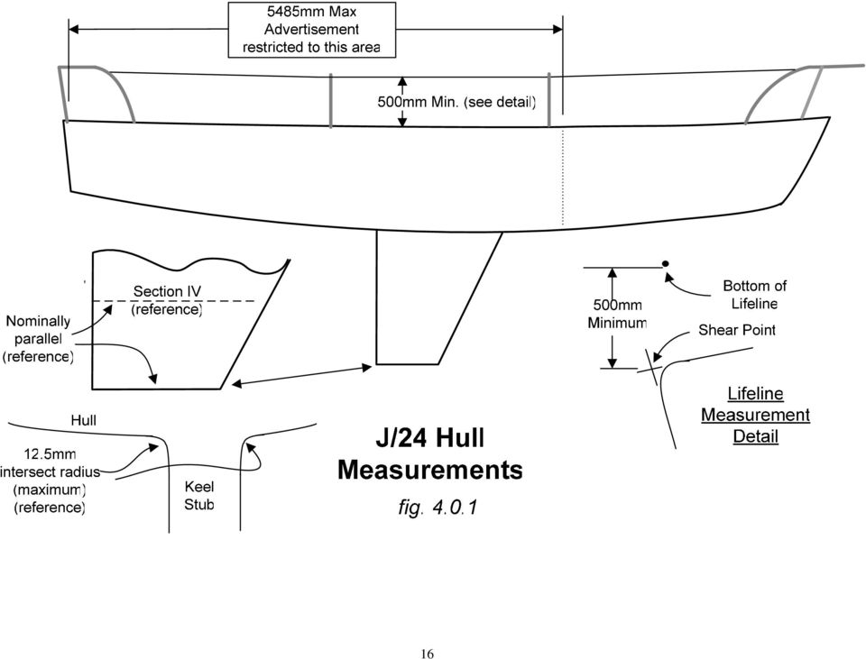
31 MEASUREMENTS TAKEN ON DECK AND PROCEDURES REGARDING DECK AND CABIN 6.0. Deck and Cabin Items ITEM 24 RULE Upper lifelines 500mm minimum above sheerline? (Yes/No) 1. Upper lifelines must be taut (no sag), of wire not less than 4mm diameter, and not less than 500mm vertically above the sheerline at all points along their length. Additional attachment points may be added to the pulpit and pushpit, but factory-installed attachment points may not be removed. The pulpit and pushpit heights shall not be altered. Measure the height at the middle stanchions (refer to fig ). 2. Because the mid point of the lifelines between the stanchions is inboard of the hull sheer the height cannot be measured directly. Instead, the lifeline height at each stanchion is measured and verified to be in compliance. Then a thin line is stretched between the stanchions at the bottom of the lifeline and the gap between the lifeline and line measured. The amount is subtracted from the stanchion height and the resulting number is the lifeline height dimension. 3. Lifelines can be secured at either or both ends by a lanyard. A maximum gap of 100mm is allowed. ITEM 25 RULE Lifeline stanchions inboard of sheer in plan? (Yes/No) 1. Referring to the two intermediate stanchions on each side of the boat, no part of a stanchion may extend beyond the vertical extension of the sheer. ITEM 26 RULE Sink/drain/water tank or stove/fuel fitted? (Yes/No) 1. If no stove is present with accompanying 1.80kg minimum weight LP gas or alcohol container, then a sink or basin must be fitted into the cabin moulding on the starboard side aft of the main bulkhead. The sink may drain overboard by means of a through hull fitting, or into a plastic container of minimum 5 liter capacity. ITEM 27 RULES 3.1.4, 3.8, 8.1.2, Fixed fittings and equipment located according to Class Rules? (Yes/No) 1. See also Rules 1.2, 1.3, 3.4, 3.5, 3.7.2, 6.1, Note: As a reminder to measurers, inspect the boat for sail track compliance with Plan A. Also note that the mainsail traveler bar may extend to the outer edges of the deck cutout but no further. 30
32 ITEM 28 RULE Dry weight without additional correctors 1. Boat weight dry prior to adding any corrector weights. Boat may already have corrector weights installed. If so confirm that they are properly installed and secured. ITEM 29 RULE Total weight of additional correctors 1. Enter the amount of the corrector weights required to bring the boat up to the minimum weight. If corrector weight s are already in place leave this value blank. Add a comment that the boat already has corrector weight s in place in the COMMENTS section. ITEM 30 RULE Basic Yacht Weight 1. Enter the sum total of ITEM 28 and ITEM 29. If corrector weights are already in place enter the value in ITEM
33 7.0. Sail Measurement Introduction Sails are not part of the Measurement Certificate but are event requirements. Dimensions for sails can be found in Appendix A of the Class Rules. It is assumed the Measurer will be consulting the Class Rules for additional information not covered here. 7.1 Site and Layout Guidelines for site selection and layout: Selecting the site for a sail measurement is an important part of regatta preparation. Working with the Regatta Chairperson early in the planning stages can make sail measurement a comfortable process for both the competitor as well as the measurement team. The site should be flat, clean, well lit, dry and out of the weather. The parquet floor of the yacht club ballroom is the site of choice, but a gymnasium, warehouse, dining room or sail loft are good sites as well. If you must measure on carpet it must be a low, level loop commercial grade material or the tape marks might move, over the duration of measurement. The criteria are: flat, clean, well lit, dry and out of the weather. The layout of the measurement area is dependent to a certain degree on the way the sail measurement team is organized and the number of measurers available. The ideal organization would be one person to coordinate the sails to be measured and keep track of the paperwork and materials, and four teams of two persons, making one team for each class sail to be measured. If the measurers and space are available, a separate measurement area for each sail makes sail measurement very fast. If required, a smaller area can be utilized using a coordinator and two or three teams of two persons by laying out the jib and genoa diagrams atop one another and the mainsail and spinnaker likewise. Using different colored tape or pens to distinguish between the sails will reduce errors. Actual placement of the diagrams can be aided by using an older suit of sails and arranging them to fit the space available. Of course sails can be measured individually, but this is not recommended for regatta s when a considerable number of sails are to be measured. Diagrams that follow fig. A.1.3.A show the areas needed for sail measurement only, they do not include the area needed for the waiting competitors and their sails. A "holding area" can be important at a large regatta. Tape should be used (carefully on the parquet floor) to layout the various minimum and maximum dimensions as shown on the diagrams shown in Appendix A. You should indicate with an arrow the side of the tape to which the measurement is to be taken and provide a description of what is being measured. Refer to the diagrams in Appendix A, Section 1.6 for examples of tape markings. Using markers or pens that don't smear or wear off is, of course, advisable. It is recommended that materials are tested before beginning to avoid leaving stains or tape residue on the parquet or carpet. As mentioned earlier, color coding the tape or using different colored marking pens will facilitate the process when two sails are laid together. The angles shown for the foot of the spinnaker are approximate and some shifting of the sails will be necessary. If it is possible to lay out our measurement area using a sail as guidelines for the angles, do so. If not, a protractor, an adjustable triangle or a hand bearing compass and a good eye work well. 32
34 7.2 General Information PRINCIPLES OF SAIL MEASUREMENT The basic principles of sail measurement are as follows: 1. The sail must be presented for measurement in a dry condition. Moisture in the material can affect the dimensions of a sail, especially the spinnaker. 2. The sail must be measured on a flat surface. 3. The tension applied to the sail must be just sufficient to remove wrinkles across the line of the measurement being taken. Measurer Reference Note: While this manual refers to laying out a floor pattern that is intended to allow a quick check of sail measurement conformance, it is a practice that is feasible only when many suits of sails are to be measured as taping down a floor area can take 1-2 hours. In cases where only a few sails are to be measured the use of a metal tape measure is more satisfactory. The sails will need to be laid out with enough tension to just remove wrinkles and measured using the dimensions indicated on the respective drawings (Figs through 7.3.4). Upon finding that the sail meets the measurement criteria the measurer is to sign, including the date, across the royalty patch onto the sail cloth REINFORCEMENT Sails may have a primary reinforcement of any flexible material of coating, and secondary reinforcing of additional layers of cloth. Any reinforcement or finishing materials or coating shall not prevent the sail from being folded or damage the fibers when folded (refer to class rule for details) ADVERTISING MARKS ISAF Measurement Instructions indicate that "Most sailmaker's like to display their name on their sails and IYRR 26 permits this to be done with certain limitations. These are: 1.) The sailmaker's mark shall fit within a square not exceeding 150mm X 150mm. 2.) The whole of the mark shall be so placed on the sail that it is not more than 15% of the length of the foot of the sail or 300mm from its tack, whichever is greater." Note: Marks shall appear on the starboard side of thejib, Main, and Genoa sails. 3.)The location of the sailmaker s mark is shown on the sail diagrams. 4.) The sailmaker's mark may be placed on each side of the sail and that the second limitation above does not apply to spinnakers. Measurers should note that some sailmaker's marks will fit within the 150mm square on the diagonal ROYALTY TAG LOCATION 1. Royalty tags are to be perminently attached to the Starboard side of the Genoa, Jib, and Main sails and near the Spinnaker clew. 33
35 7.2.5 SIGNING SAILS 1. When a measurer is satisfied that a sail complies with all rules, he/she is required to stamp, sign and date the sail per class rule Note: the signature must cross from the royalty tag and onto the sail cloth. 2. The type of pen used to endorse sails is very important because the signature has to remain visible for several years. Ordinary ball point or felt tip pens are not adequate. Waterproof ink must be used. If in doubt, mark a rag with the pen you intend to use and launder in hot water to see whether the marking remains. Measurers Reference Note: When inspecting sails that have been previously stamped, re-sign and/or stamp the sail to identify those sails selected for the regatta in question Procedures for Sail Measurement MAIN SAIL MEASUREMENT PROCEDURE 1. Using the measurement points as shown on Fig , measure leech, batten pocket locations, reef point, and headboard. 2. Fold Head Measurement Point to Tack Measurement Point as shown in Fig. A.2.b. Mark sail at Half Height. 3. Fold Head Measurement Point to Half Height Mark as shown in Fig. A.2.b and mark the 3/4 Height. And fold Clew Measurement Point to Half Height Mark as shown in Fig. A.2.c and mark the 1/4 Height. 4. Unfold sail, measure the ¼ Height Width as indicated in Fig. A2.a. 5. In similar fashion measure the ½ and ¾ Height Widths as indicated in Fig A2.a 6. Note that width measurements shall be taken from a point on the leech, or from a point on a line bridging any hollows in the leech to the nearest point on the luff (i.e. perpendicular to the luff). 7. Referring to fig , check the following: A. Top batten length B. Intermediate batten lengths C. Lower batten length D. Batten width E. Window size and number F. Batten pocket reinforcement G Class emblem conforms to class rule H. Sail numbers in accordance with I. Sailmaker's label J. Cloth weight marked and signed by the sailmaker on headboard per K. Check that any advertisement is confined to the lower third of the sail (2800mm from the foot. 8. Check the minimum length of the foot boltrope at 2300mm. 9. Record Royalty number, stamp, sign and date sail. 34
36 7.3.2 JIB MEASUREMENT PROCEDURE 1. Measure the width of the head (at right angle to luff). Using the measurement points shown below, measure the luff length & reinforcement as indicated in Fig Using the Clew Measurement Point indicated below, measure with tape the Diagonal (LP). 3. Referring to fig , check the following: A. Top batten length B. Lower batten length C. Window size D. Hank width E. Hank spacing F. Sailmaker's label G. Cloth weight marked and signed by the sailmaker on headboard per H. Check leech to insure it is not convex. 4. Record Royalty number, stamp, sign, and date sail GENOA MEASUREMENT PROCEDURE 1. Measure the width of the head (at right angle to luff). Using the measurement points shown below, measure the luff length & reinforcement as indicated in Fig Using the Clew Measurement Point indicated below, measure with a tape the Diagonal (LP). 3. Referring to fig check the following: A. Window size B. Hank width C. Hank spacing D. Sailmaker's label E. Sail numbers in accordance with and located no higher than 50% of the luff. F. Cloth weight marked and signed by the sailmaker on headboard per Record Royalty number, stamp, sign and date sail SPINNAKER MEASUREMENT PROCEDURE 1. Fold sail in half, leeches together, see Fig Measure leech, stretch sail only enough to take wrinkles out of measured area. 3. Fold centerfold over to leeches, see Fig , and measure centerfold. 4. Mark girth measurement points (2030mm & 4060mm) on centerfold and on leech. 5. Open sail to configuration shown in Fig Measure, with tape, both midgirth dimensions and foot. See Fig Referring to fig check the following: 35
37 A. Sail numbers in compliance with B. Sailmaker's label - C. Cloth weight marked and signed by the sailmaker on headboard per Check that any advertisement conforms to ISAF restrictions (at least clearly separated from national letters and sail numbers) 9. Record Royalty number, stamp, sign and date sail. 36
38 Luff 150 Max 115 Max Head Point Head Point Bolt Rope or Luff Tape NOTE: Head point is folded to the clew point to mark the 1/2 height point on the leech. Clew point is folded to the 1/2 height point to mark the 1/4 height point on the leech. Head Point is folded to the 1/2 point to mark the 3/4 height point on the leech. 2800mm Max Advertisement restricted to this area 1775 Min 9170 Max Leech 1/2 Point 740 Max 990 Max 1/4 Point Reef Point (Optional) 3/4 Point 990 Max 610 Max 2600 Max 1000 Min (to bearing point of cringle) 1175 Max 1980 Max 50 mm. Max Batten Width 1775 Min NOTE: Window Size 1500 mm. Max in any direction. Sail Numbers 300 mm. height x 200 mm. width x 45 mm. thick 60 mm. spacing. Cloth weight marked on head, signed and dated by sailmaker per class Rule Leech Clew foot 445 max Sailmakers label (150 x 150 max.) Tack Clew Point Bolt Rope 2300mm Min bolt rope length Slug Foot J-24 Mainsail Measurement fig
39 38
40 450 max 600 max 600 max
41 Head Point 2030 radius Centerline of Cringle 4060 Radius 3/4 Height 1600 min Tapes Luff Center Seam Length Center Seam Fold Half Height Leech Lengths Headpoint to Leech Point foot Note: Sail Numbers 300 mm height x 200 mm width (except "1" and "I") x 45 mm thick - 60 mm spacing Cloth weight marked on head, signed and dated by sailmaker per class Rule Leach Points J-24 Spinnaker Measurement (Sail folded vertically about center seam.) fig. Fig
Class Rules Effective 1st April 2013
 Class Rules Effective 1 st April 2013 TABLE OF CONTENTS CLASS RULES 1 OBJECTIVES OF THE CLASS RULES 1 2 ADMINISTRATION 1 3 CONSTRUCTION AND MEASUREMENT 3 4 REQUIRED EQUIPMENT WHEN RACING 10 5 CREW 10 6
J/24 Tuning Guide San Diego models
 San Diego models Thanks very much for purchasing your J/24 sails from North Sails we appreciate your business. The following tuning guide is meant to be a starting point in setting up your boat for your
THE FLYING SCOT A BASIC GUIDE TUNING AND SAIL TRIM By Harry Carpenter
 THE FLYING SCOT A BASIC GUIDE TO TUNING AND SAIL TRIM By Harry Carpenter Tuning the Flying Scot Rig Boat set up In setting the mast rake on a Flying Scot, most Scot sailors run a tape measure up the mast
DRAGONFLITE 95 RESTRICTED CLASS RULES 2016
 DragonFlite Force 95, Restricted Class Rules 2016 2013 Version 1.1 1.0 DRAGONFLITE 95 RESTRICTED CLASS RULES 2016 Version 1.1 DF Racing Rules Committee 2016 Introduction The DragonFlite 95 (DF95) project
DRAGON FORCE RESTRICTED CLASS RULES 2014
 Dragon Force Restricted Class Rules 2014 2013 Version 1.3 1.0 DRAGON FORCE RESTRICTED CLASS RULES 2014 Version 1.3 Dragon Force Rules Committee 2014 Introduction The Dragon Force project started in 2011
Weta Class Rules. This introduction provides an informal background and is not part of the Weta class rules.
 Introduction The Weta is a trimaran developed by Weta Marine Ltd. Weta hulls, beams, hull appendages, rigs and sails shall only be manufactured by Weta Marine Ltd or their appointed manufacturers. A hull,
PLATU 25 CLASS RULES. The PLATU 25, designed by Bruce Farr, was adopted as a recognised class in November 2005.
 PLATU 25 CLASS RULES 2008 The PLATU 25, designed by Bruce Farr, was adopted as a recognised class in November 2005. INDEX PART I ADMINISTRATION Section A General A.1 Language... A.2 Abbreviations... A.3
Quantum Tuning Guide 2002
 Quantum Tuning Guide 2002 A reference guide to the set-up, tuning, and trim for the Beneteau First 36.7 One-Design Class Bill O Malley - Quantum Sail Design Group Beneteau First 36.7 One-Design Class Administrator
J/70 Tuning Guide. onedesign.com Follow North Sails on... For any question you may have on tuning your J/70 for speed, contact our experts:
 Photo Paul Todd/OUTSIDE IMAGES For any question you may have on tuning your J/70 for speed, contact our experts: Tim Healy 401-683-7997 tim.healy@northsails.com Will Welles 401-683-7997 will.welles@northsails.com
SAILMAKERS INSTRUCTIONS WEBSITE VERSION
 SAILMAKERS INSTRUCTIONS WEBSITE VERSION CONTACT FORESPAR FOR A DRAWING AND VESSEL-SPECIFIC DIMENSIONAL DATA (ITEMS A - K ON PAGE 2) SPECIAL NOTE TO SAILMAKERS: PLEASE READ THESE INSTRUCTIONS CAREFULLY
INTERNATIONAL FIREBALL CLASS RULES 2003
 INTERNATIONAL FIREBALL CLASS RULES 2003 Copyright 2003 Fireball International IFCR 2003 - Page 1 INTERNATIONAL FIREBALL CLASS RULES - INDEX page 1 GENERAL...5 1.1 Objective...5 1.2 Language...5 1.3 Design...5
INTERNATIONAL TECHNO 293 CLASS RULES
 INTERNATIONAL TECHNO 293 CLASS RULES INDEX INTRODUCTION... 3 C.9 Sails...8 PART I ADMINISTRATION Section A General A.1 Language... 4 A.2 Abbreviations... 4 A.3 Authorities and Responsibilities4 A.4 ISAF
Chapter 3 Installing Over-the-Post Railing on an L-Shaped Stair
 49 Chapter 3 Installing Over-the-Post Railing on an L-Shaped Stair In this chapter: The Over-the-Post Balustrade System Determining the Rail Centerline Using Rail Bolts Making a Pitch Block Laying Out
INTERNATIONAL J/80 CLASS RULES 2013
 INTERNATIONAL J/80 CLASS RULES 2013 Published Date: 4 th April 2013 Effective Date: 19 th April 2013 INTRODUCTION This introduction only provides an informal background and the International J/80 Class
INSTALLATION MANUAL «SD» RANGE
 INSTALLATION MANUAL «SD» RANGE The FACNOR model SD is the easiest Reefing System in the world to install. You will see, it is designed for a quick and simple installation. It can be fitted without precise
MM 45 Charter Catamaran Subchapter "T" - 49 Passenger
 MM 45 Charter Catamaran Subchapter "T" - 49 Passenger Make: MM 45 Charter Catamaran Model: Subchapter "T" - 49 Passenger Length: 45 ft Price: $ 600,000 Year: 2015 Condition: New Location: Portland, United
These instructions are for using number templates to
 by John Davis These instructions are for using number templates to easily number your sails with a uniform and readable method. The template numbers are sized and spaced to meet international regulations,
EXTREME 40 CLASS RULES 2012
 EXTREME 40 CLASS RULES 2012 EFFECTIVE FROM 1 ST AUGUST 2012 Published 1/8/12 INDEX PART I ADMINISTRATION Section A General A.1 Language... 3 A.2 Abbreviations... 3 A.3 Authorities... 3 A.4 Administration
Soch Sails DF65 Rig Kit Manual
 Soch Sails DF65 Rig Kit Manual A simple yet useful guide to building a new rig for a DF65 written in a manner that you can understand without needing a degree in rocket science or membership of MENSA.
Gate Leg Drop Leaf Table Plans
 Preparing the table top blanks: Cut and glue enough 3/4 stock to make three panels 40 long by 24 wide (they will be cut to final size at a later time). While the glue dries we will work on the legs. Preparing
Battcar Installation Manual System B CB and Slider Cars 6mm Clevis Pin
 Battcar Installation Manual System B CB and Slider Cars 6mm Clevis Pin CB/Slider Systems Parts List Thank you for puchasing Harken's B Battcar system. Please read manual before assembling system. Intermediate
INTERNATIONAL J/70 CLASS RULES
 INTERNATIONAL J/70 CLASS RULES Version 2012-03 Effective Date: 15 August 2012 INTRODUCTION Prior to the Class being formed with suitable By-Laws in place and with at least 200 active owners, J Boats Inc.
BUILDINGA 1/10 SCALE FLATBED TRAILER
 VOLUME 1, ISSUE 1 BUILDINGA 1/10 SCALE FLATBED TRAILER BUILT, DESIGNED & WRITTEN BY NATHAN MYERS MATERIALS: FEATURES: While the design was kept simple to allow anyone to be able to build their own trailer,
How To Sail A Winner Optimist
 Rigging Manual Winner Optimist Congratulation on the purchase of your new Winner Optimist. Reading this manual will help you with the rigging and preparation for correct use and subsequent high enjoyment
COMMON SAILING GLOSSARY OF TERMS
 COMMON SAILING GLOSSARY OF TERMS Abeam Aboard Anchor Aft Off to the side of a vessel at right angles to the boat s centerline. On or in the boat A device used to hold a boat to the sea bottom At, near
class 3 Sails conform to ISAF rules
 3 Sails conform to ISAF rules Order all 3 suits together and deduct 5. from the total plus post and packing. Sails are available in Scrim, Satin Film and traditional Dacron. Top Suit Scrim or Satin Film
Guidelines for Earthquake Bracing of Residential Water Heaters
 Guidelines for Earthquake Bracing of Residential Water Heaters Department of General Services Division of the State Architect 1102 Q Street, Suite 5100 Sacramento, CA 95814 Phone: (916) 324-7099 Fax: (916)
Pole Lathe and Shave Horse Design
 Pole Lathe and Shave Horse Design These pictures and accompanying words are Copyright Michael Hughes February 2002. They are not to be re-produced, in part or whole, without permission from the author.
Rudder Repair and refinish
 Rudder Repair and refinish Montgomery 23 Dauntless The before photograph A receipt found inside the boat showed a previous owner had enlisted a boat yard to perform maintenance on the rudder by shortening
How to Install Hardwood Flooring Over a Sub Floor
 How to Install Hardwood Flooring Over a Sub Floor Installation Preparation Instructions Read the entire instructions before starting your project. 1) INSPECT EACH PLANK (see fig. a) Wood is a natural product
COMPLIMENTARY WOODWORKING PLAN
 COMPLIMENTARY WOODWORKING PLAN Adirondack Chair This downloadable plan is copyrighted. Please do not share or redistribute this plan in any way. It has been created for Wilton Tools, a division of WMH
DIY CABINET REFACING INSTALLATION GUIDE
 DIY CABINET REFACING INSTALLATION GUIDE CABINET REFACING INSTALLATION Are you ready to reface your outdated cabinets? This guide will show you how to install your new Facelifters Cabinet Refacing Products
Guidelines for Earthquake Bracing Residential Water Heaters
 Guidelines for Earthquake Bracing Residential Water Heaters Department of General Services Division of the State Architect In accordance with the Health and Safety Code Section 19215, the Division of the
A completely new mast from Seldén
 A completely new mast from Seldén Long, stiff and loaded Modern sailcloth and sail design call for longitudinal stability. Most rating systems call for rigs without running backstays. Seldén s new mast
PLASTIMO JIB REEFING SYSTEMS S-SERIES 406-S 608-S 810-S
 PLASTIMO JIB REEFING SYSTEMS S-SERIES 406-S 608-S 810-S GB ASSEMBLY INSTRUCTIONS FOR S-SERIES 406-S 608-S 810-S I N D E X Technical specifications of 406-S, 608-S, 810-S 3 Description of specific parts
Complete Dovetail Jig Instructions
 Complete Dovetail Jig Instructions 18 15 1 12 13 8 (22818) 19 17 16 4 3 6 14 5 9 9 11 10 2 PARTS LIST - COMPLETE DOVETAIL JIG Introduction Your new dovetail jig will cut Full Through Dovetails and three
DSM http://www.dsmmfg.com 1 (800) 886-6376
 886-6376") DESIGN GUIDE FOR BENT SHEET METAL This guide discusses how the bends are made, what thicknesses of sheet metal are commonly used, recommended bend radius to use when modeling the part, some practical limits
DESIGN GUIDE FOR BENT SHEET METAL This guide discusses how the bends are made, what thicknesses of sheet metal are commonly used, recommended bend radius to use when modeling the part, some practical limits
Larger versions have been built for a Cal-40, a Santa Cruz 52 and a Beneteau 57.
 Emergency Rudder Design - the Soft Rudder by Paul Kamen The emergency rudder is one of those required big-ticket items that can become a complicated and expensive part of Pacific Cup boat preparation.
March 14, 2007. Installation of Bay, Bow and Garden Windows
 March 14, 2007 Re: Installation of Bay, Bow and Garden Windows Attached are the Atrium Companies, Inc recommendation for the installation of bay, bow and garden windows. These instructions were developed
North Carolina FFA Association Agricultural Mechanics Career Development Event
 North Carolina FFA Association Three (3) of the following Agricultural Mechanics Performance Skills will be selected for the state competition. North Carolina FFA Association Agricultural Mechanics Performance
Freehand Sketching. Sections
 3 Freehand Sketching Sections 3.1 Why Freehand Sketches? 3.2 Freehand Sketching Fundamentals 3.3 Basic Freehand Sketching 3.4 Advanced Freehand Sketching Key Terms Objectives Explain why freehand sketching
BUILD A TABLETOP LOOM
 BUILD A TABLETOP LOOM From 1" x 2" stock (actual 3/4" x 1"1/2) cut: 4 pieces 15" long 4 pieces 5"1/2 long Use the above to make 2 frames for the front and back of the loom. From 1" x 4" stock (actual 3/4"
Appendix B Supplement: Fin Positioning
 Appendix B Supplement: Fin Positioning This supplement contains Techs related to the postitioning of fins..they relate the step-by-step details of what is a logical series of steps given the fin location
INTERNATIONAL RCEBOARD CLASS ASSOCIATION CLASS RULES
 INTERNATIONAL RCEBOARD CLASS ASSOCIATION CLASS RULES The International Raceboard Class was adopted as an International Class in 1990. PART I ADMINISTRATION Section A General A.1 Language... A.2 Abbreviations...
How to Build Your Own CornHole Game
 How to Build Your Own CornHole Game DIMENSIONS Here is a diagram with the basic measurements for the Cornhole board game. SUPPLIES 1/2 thick sheet of plywood one 4 x4 or two 2 x4 s 8 long 2 4 s (4) 4 1/2
FREEBIRD THE ORIGINAL D.I.Y. ORNITHOPTER! Tools and Glue. Required Materials
 Do not try to make your ornithopter using "household materials". If you want it to fly, you have to build it right. FREEBIRD THE ORIGINAL D.I.Y. ORNITHOPTER! Wingspan: 16 inches Weight: 1/4 ounce The Ornithopter
Chapter 10 - Scaffolding Systems
 Chapter 10 - Scaffolding Systems Contents Chapter 10 - Scaffolding Systems... 10-1 Check and Oil the Pump Jacks... 10-4 Set Pump Jack Brackets... Error! Bookmark not defined. Set Pump Jack Poles... 10-5
Installing Window and Door Mouldings
 Installing Window and Door Mouldings About Window and Door Mouldings The trim around windows and doors greatly influences the look and style of your interior. They also bridge the gaps and cover spaces
TECHNICAL SPECIFICATION SERIES 8000 PRECAST CONCRETE
 TECHNICAL SPECIFICATION SERIES 8000 PRECAST CONCRETE TECHNICAL SPECIFICATION PART 8000 - PRECAST CONCRETE TABLE OF CONTENTS Item Number Page 8100 PRECAST CONCRETE CONSTRUCTION - GENERAL 8-3 8101 General
SPECIFICATION Aluminum Module Frames. Allowed anodization before fabrication for clear frames.
 SPECIFICATION Allowed anodization before fabrication for clear frames. Page 2 of 9 1. SCOPE 1.1. This document provides general requirements for aluminum frames used in the assembly of photovoltaic modules.
Ceiling Mounted Folding Attic Ladders Installation Instructions
 Ceiling Mounted Folding Attic Ladders Installation Instructions WARNING Before you start installing your new Louisville Ceiling Mounted Folding Attic Ladder, you must read and understand the following:
HOW TO MAKE A MOTOR BRACKET
 HOW TO MAKE A MOUNTING BRACKET FOR AN ELECTRIC MOTOR Often, brackets supplied with purchased items (e.g. electric motors or servos) are not ideally suited for fitting into our models or they are not supplied
Sheet Metal Shearing & Bending
 Training Objective After watching the program and reviewing this printed material, the viewer will gain a knowledge and understanding of the principles and machine methods of shearing and bending sheetmetal
DRAWING INSTRUMENTS AND THEIR USES
 Chapter - A DRAWING INSTRUMENTS AND THEIR USES Drawing Instruments are used to prepare neat and accurate Drawings. To a greater extent, the accuracy of the Drawings depend on the quality of instruments
Reflection and Refraction
 Equipment Reflection and Refraction Acrylic block set, plane-concave-convex universal mirror, cork board, cork board stand, pins, flashlight, protractor, ruler, mirror worksheet, rectangular block worksheet,
How to Build a Poker Table
 How to Build a Poker Table www.pokertablematerials.com 10-Person Poker Table- 96 x 48 These are step by step instructions for building a poker table. The table will measure 48" x 96" and have a 4" wide
Traditional Sonar and DSI Sonar Installation
 Traditional Sonar and DSI Sonar Installation This document covers the installation of the transducer and display unit installation, which includes connecting the unit to power and installing the unit on
AISI CHEMICAL COMPOSITION LIMITS: Nonresulphurized Carbon Steels
 AISI CHEMICAL COMPOSITION LIMITS: Nonresulphurized Carbon Steels AISI No. 1008 1010 1012 1015 1016 1017 1018 1019 1020 1021 1022 1023 1024 10 1026 1027 1029 10 1035 1036 1037 1038 1039 10 1041 1042 1043
DURAS INFLATABLE BOAT OWNER'S MANUAL
 DURAS INFLATABLE BOAT OWNER'S MANUAL Table of Contents About your new Duras Inflatable Boat Page 1 Assembly Instruction Page 3 Motor Installation Page 5 Capacities Page 5 Troubleshooting Page 6 Using
Assembly Instructions Basic Folding-Leg Box Frame Style
 Assembly Instructions Basic Folding-Leg Box Frame Style Basic Folding Leg Cornhole Board Concept 1 2 12 3 1 2 3 15 16 4 1 4 52 9 R1 3 4 6 21 48 12 1 4 Bolt Washer 9 13 16 35 Washer Double Nut CornholePlayers.net
Stair Parts Installation. Tricks
 Stair Parts Installation Tips & Tricks Introduction Your DIY staircase guide Welcome to the Stairpart home installation guide. Your stairway is both a functional and focal point in your home, so keeping
KITCHENS. Tip PAGE 1 FITTING YOUR KITCHEN GUIDE. How to mark out a kitchen. Tools required for installing a kitchen STEP ONE STEP TWO STEP THREE
 FITTING YOUR KITCHEN GUIDE How to mark out a kitchen PAGE 1 Before starting on the installation, measure 870mm from the lowest point of the floor and mark a datum line around the room to indicate where
STAIR TREAD & RISER INSTALLATION GUIDELINES
 STAIR TREAD & RISER INSTALLATION GUIDELINES ARTISTIC FINISHES DOES NOT WARRANTY THE COMPLETENESS OR ACCURACY OF ANY INSTALLATION. THE INSTALLATION CONTRACTER MUST HAVE THE EXPERIENCE AND KNOWLEDGE TO COMPLETE
Speed-Mat Rectangle Cutter
 Speed-Mat Rectangle Cutter 1 Honeycomb baseboard. 2 Left hold down. 14 3 Bottom hold down. 4 4 Left / right rule. 8 5 8 5 Left / right rule pointer. 1 6 Top / bottom rule. 7 Top / bottom rule pointer.
Gear PEPSI CAN STOVE INSTRUCTIONS
 Gear PEPSI CAN STOVE INSTRUCTIONS [NOTE: Updated Instructions are now available. The new stove is less likely to develop flame leaks and the fuel/air mixture is improved. Instructions for a simmer ring
Picnic Table Plans. Made out of a single sheet of plywood, it s also portable! By Kevin Ayer. This children's picnic table would
 Picnic Table Plans Made out of a single sheet of plywood, it s also portable! By Kevin Ayer Materials One 4- by 8-foot sheet of 3 4-inch AC plywood Twelve 11 4-inch wood screws Primer and exterior paint
Dee s tuning and sailing thoughts for the Farr 400
 Dee s tuning and sailing thoughts for the Farr 400 I have had a great time sailing the Farr 400 both in Dubai, the Med and San Francisco. In all sorts of conditions, 0-30 knots.. The boat is light, powerful
OPERATING P L AYA B I L I T Y P R E C I S I O N D E S I G N
 P L AYA B I L I T Y P R E C I S I O N P E R F O R M A N C E OPERATING INSTRUCTIONS FOR: GolfWorks Loft and Lie Gauges code: HGCG/DGCG/LOLI2 4820 Jacksontown Road P.O. Box 3008 Newark, Ohio 43058-3008 Toll-Free:
Junkers Ju 88 Manual Version 1.2 13 March 2008
 Junkers Ju 88 Manual Version 1.2 13 March 2008 Specifications Wingspan: 49.75 inches Area: 339 square inches Length: 36.12 inches Power: 2x BP21 Brushless 2x Speed-400 Copyright 2007 Thomas A. Jacoby and
Dock Hardware & Accessory Products Catalog
 Dock Hardware & Accessory Products Catalog Product Page # Product Page # Angle Brackets/Clips 8 Back Up Plate 5 Backing Plate/Hurricane Stop 10 Carriage Bolt Sets 4 Chain Retainer 10 Connector Pin Set
THE DEWALT RAFTER SQUARE
 THE DEWALT RAFTER SQUARE The DEWALT Rafter Square is designed to provide a quick, accurate, and repeatable means for laying out and cutting the various cuts on common, hip, valley and jack rafters used
Rigging Manual. 1 Parts of the Hull. 2 Parts of the Sail. 3 Sunfish Mast Kit. 4 Bailer Installation. 5 Ratchet Block Installation
 SUNFISH SUNFISH RACE SUNFISH Rigging Manual 1 Parts of the Hull Go-fast tip number one: Read this rigging guide first. 2 Parts of the Sail 3 Sunfish Mast Kit 4 Bailer Installation 5 Ratchet Block Installation
Lunette 2 Series. Curved Fixed Frame Projection Screen. User s Guide
 Lunette 2 Series Curved Fixed Frame Projection Screen User s Guide Important Safety and Warning Precautions Please follow these instructions carefully to ensure proper maintenance and safety with your
S&W Race Cars and Components, Inc.
 S&W Race Cars and Components, Inc. 11 Mennonite Church Road Spring City, PA 19475 TECH & INFORMATION: 610-948-7303 ORDERS: 1-800-523-3353 OFFICE FAX: 610-948-7342 E-Z INFO FAX 610-792-1234 CAUTION!!! -
Skirt 1 / 4. The Skirt. The skirt patterns were downloaded from Mark's site but they need expanding before they can be used.
 Skirt 1 / 4 The Patterns The Skirt The skirt patterns were downloaded from Mark's site but they need expanding before they can be used. I used Corel Draw's real world dimensions to expand the patterns
These instructions will show you how to install an internal door into a non-loadbearing partition wall. The instructions are split into three parts.
 No 8 in the series of 'How to' brochures produced by PlaceMakers, New Zealand How to Frame and Hang a Door These instructions will show you how to install an internal door into a non-loadbearing partition
UB1 AIR CONDITIONING UNIT INSTALLATION INSTRUCTIONS
 UB1 AIR CONDITIONING UNIT INSTALLATION INSTRUCTIONS INSTALLATION INSTRUCTIONS: Carefully read these instructions before installing your new air-conditioner. AUSTRALIAN AUTOMOTIVE AIR AL00500054E 1 Table
TopSky DLG Installation Manual
 TopSky DLG Installation Manual Attention: Because after the compound materials solidify, there will be ammonia iris on the surface, which affect the bonding strength afterwards. Please polish with sandpaper
SHELVES. www.tedswoodworking.com
 SHELVES It's rare that bookshelves look as interesting as the objects you display on them. After all, how much can you decorate the edges of your shelves and sides? This unit is unusual because the shelves
39HQ Airovision Air Handling Units
 39HQ Airovision Air Handling Units Mounting instructions CONTENTS 1 - TRANSPORT AND LIFTING INSTRUCTIONS... 3 1.1 - General... 3 1.2 - Transport and storage... 3 1.3 - Roof edge protection during transport
EQUIPMENT SET UP RECURVE BOW
 EQUIPMENT SET UP RECURVE BOW Archery Australia Inc Coaching and Standards Committee Proudly Sponsored By EQUIPMENT SET UP RECURVE BOW It is important that equipment to be used must be set up correctly
I BEAM TRACK INSTALLATION
 PDQ 0/700 FESTOON SYSTEM INSTALLATION AND MAINTENANCE INSTRUCTIONS INTRODUCTION The PDQ Festoon System was designed to run on one of three sizes of I-beams: S x., S8 x 8. and S x.. System trolleys must
Owner's Manual & Assembly Instructions
 Owner's Manual & Assembly Instructions PM01 BASE KIT Model No. FDN1014 717090311 CAUTION: SOME PARTS HAVE SHARP EDGES. CARE MUST BE TAKEN WHEN HANDLING THE VARIOUS PIECES TO AVOID A MISHAP. FOR SAFETY
Wind Direction Smart Sensor (S-WDA-M003)
") (S-WDA-M003) The Wind Direction smart sensor is designed to work with HOBO Stations. The smart sensor has a plug-in modular connector that allows it to be added easily to a HOBO Station. All sensor parameters
(S-WDA-M003) The Wind Direction smart sensor is designed to work with HOBO Stations. The smart sensor has a plug-in modular connector that allows it to be added easily to a HOBO Station. All sensor parameters
Handling, Erection and Bracing of Wood Trusses
 Handling, Erection and Bracing of Wood Trusses Follow these guidelines for safe installation of Wood Trusses. These guidelines should not be considered to be the only method for erecting and bracing of
27th session 20 December 2011. Resolution A.1045(27) Adopted on 30 November 2011 (Agenda item 9) PILOT TRANSFER ARRANGEMENTS
 Adopted on 30 November 2011 (Agenda item 9) PILOT TRANSFER ARRANGEMENTS") E ASSEMBLY A 27/Res.1045 27th session 20 December 2011 Agenda item 9 Original: ENGLISH Resolution A.1045(27) Adopted on 30 November 2011 (Agenda item 9) PILOT TRANSFER ARRANGEMENTS THE ASSEMBLY, RECALLING
E ASSEMBLY A 27/Res.1045 27th session 20 December 2011 Agenda item 9 Original: ENGLISH Resolution A.1045(27) Adopted on 30 November 2011 (Agenda item 9) PILOT TRANSFER ARRANGEMENTS THE ASSEMBLY, RECALLING
Learn to Sail at MIT
 Learn to Sail at MIT Please read this before the next class and practice your knots: the bowline and the stunsail tack bend. Rigging Check with the dock staff to see if there are any restrictions. Grab
SAMPLE TEST PAPER - I
 SCHEME E SAMPLE TEST PAPER - I Course Name : Mechanical Engineering Group Course Code : AE/PG/PT/ME/MH/FE Semester : Third Subject : Mechanical Engineering Drawing 12042 Time : 90 Minutes Marks: 25 Instruction:
Pink & White Gel Tip Overlay Rules, Judges Instructions & Criteria Student Division Competition Rules
 Competition Rules 1. Total time allowed 3 hours (180 minutes) 2. These are traditional square style competition nails. 3. The nails must be applied with Tips and Gel overlay 4. The competitor must apply
Herringbone Pattern Flooring
 Herringbone Pattern Flooring If it s not marked NOFMA, it s not certified. Handling, Storage, Installation and Tips Herringbone is generally manufactured from 3/4 x 2 ¼ or ¾ x 1-1/2 standard tongue & groove
Field Application Note
 Field Application Note Reverse Dial Indicator Alignment RDIA Mis-alignment can be the most usual cause for unacceptable operation and high vibration levels. New facilities or new equipment installations
Navico-Northstar 2kW JRC Radar Package, Scanner Cable Removal and Replacement
 Navico-Northstar 2kW JRC Radar Package, Scanner Cable Removal and Replacement This work instruction describes the methods and means for which to remove and reinstall optional scanner cable configurations
Installation Instructions For Slider Casement Air Conditioners
 Installation Instructions For Slider Casement Air Conditioners NOTE: These instructions describe installation in a typical wood framed window with a wood SLIDE-BY sash, or installation in a metal CASEMENT
FORM DESIGN. easy to work with, and generally available.
 Forms play a major role in concrete construction. They give the plastic concrete its shape and hold it until it hardens. Forms protect the concrete, assist in curing it, and support any reinforcing rods
The Bonelle Tool and Cutter Grinder
 The Bonelle Tool and Cutter Grinder The grinder was constructed about 1987 and exhibited at the 89th Model Engineering exhibition where it was awarded a bronze medal (see ME Vol164 No 3868 page 273). Subsequently
INSTALLATION INSTRUCTIONS for Premium Pocket Windows (JII022) IMPoRtaNt INFoRMatIoN & glossary. safety & HaNdlINg
 IMPoRtaNt INFoRMatIoN & glossary. safety & HaNdlINg") Thank you for selecting JeLd-weN products. Attached are JeLd-weN s recommended installation instructions for pocket (replacement) double-hung, casement, awning, picture or transom windows, designed to
Thank you for selecting JeLd-weN products. Attached are JeLd-weN s recommended installation instructions for pocket (replacement) double-hung, casement, awning, picture or transom windows, designed to
Mobile Home Pre-Inspection Checklist
 Mobile Home Pre-Inspection Checklist TWO (2) STEP INSPECTION PROCESS STEP ONE: CALL FOR THE FIRST INSPECTION WHEN THESE ITEMS ARE COMPLETE. 1. Septic tank installed and plumbing complete. (SEE PLUMBING
Router Table Plans. www.bobsplans.com
 www.bobsplans.com Router Table Plans Increase the capabilities of your router with this weekend project. Features a sliding fence with EZ-Mount clamps. These clamps are simple to make and grip tightly
OD 1401 9 PRECISION MEASURING INSTRUMENTS
 SUBCOURSE EDITION OD 1401 9 PRECISION MEASURING INSTRUMENTS PRECISION MEASURING INSTRUMENTS SUBCOURSE OD1401 EDITION 9 Unites States Army Combined Arms Support Command Fort Lee, VA 23801-1809 5 CREDIT
CHOOSING RIGS for Marblehead class yachts
 January 2006 SAILSetc Miscellaneous Information MIM02 CHOOSING RIGS for Marblehead class yachts introduction The unrestricted nature of the class rules and the relatively large number of rigs permitted