Chapter 8 Planning GPS Control Surveys
|
|
|
- Edward Mills
- 7 years ago
- Views:
Transcription
1 Chapter 8 Planning GPS Control Surveys 8-1. General Using differential carrier phase GPS surveying to establish control for USACE civil and military projects requires operational and procedural specifications that are a project-specific function of the control being established. To accomplish these surveys in the most efficient and costeffective manner, and to ensure that the required accuracy criteria are obtained, a detailed survey planning phase is essential. This chapter defines GPS survey design criteria and related observing specifications required to establish control for USACE military construction and civil works projects. Information on cost for GPS surveys can be found in Chapter 12, and information on using GPS for hydrographic surveys can be found in EM Required Project Control Accuracy The first step in planning GPS control surveys is to determine the ultimate accuracy requirements. Survey accuracy requirements are a direct function of specific project functional needs, that is, the basic requirements needed to support planning, engineering design, maintenance, operations, construction, or real estate. This is true regardless of whether GPS or conventional surveying methods are employed to establish project control. Most USACE military and civil works engineering/construction activities require relative accuracies (i.e., accuracies between adjacent control points) ranging from 1:1,000 to 1:50,000, depending on the nature and scope of the project. Few USACE projects demand relative positional accuracies higher than the 1:50,000 level (Second-Order, Class I). Since the advent of GPS survey technology, there has been a tendency to specify higher accuracies than necessary. Specifying higher accuracy levels than those minimally required for the project can unnecessarily increase project costs. a. Project functional requirements. Project functional requirements must include planned and future design, construction, and mapping activities. Specific control density and accuracy are designed from these functional requirements. (1) Density of control within a given project is determined from factors such as planned construction, site plan mapping scales, master plan mapping scale, and dredging and hydrographic survey positioning requirements. (2) The relative accuracy for project control is also determined based on mapping scales, design/construction needs, type of project, etc. Most site plan mapping for design purposes is performed and evaluated relative to American Society of Photogrammetry and Remote Sensing (ASPRS) standards. These standards apply to photogrammetric mapping, plane table mapping, total station mapping, etc. Network control must be of sufficient relative accuracy to enable hired-labor or contracted survey forces to reliably connect their supplemental mapping work. b. Minimum accuracy requirements. Project control surveys shall be planned, designed, and executed to achieve the minimum accuracy demanded by the project s functional requirements. In order to most efficiently utilize USACE resources, control surveys shall not be designed or performed to achieve accuracy levels that exceed the project requirements. For instance, if a Third- Order, Class I accuracy standard (1:10,000) is required for offshore dredge/survey control on a navigation project, field survey criteria shall be designed to meet this minimum standard. c. Achievable GPS accuracy. As stated previously, GPS survey methods are capable of providing significantly higher relative positional accuracies with only minimal field observations, as compared with conventional triangulation, trilateration, or EDM traverse. Although a GPS survey may be designed and performed to support lower accuracy project control requirements, the actual results could generally be several magnitudes better than the requirement. Although higher accuracy levels are relatively easily achievable with GPS, it is important to consider the ultimate use of the control on the project in planning and designing GPS control networks. Thus, GPS survey adequacy evaluations should be based on the project accuracy standards, not those theoretically obtainable with GPS. (1) For instance, an adjustment of a pair of GPSestablished points may indicate a relative distance accuracy of 1:800,000 between them. These two points may be subsequently used to set a dredging baseline using 1:2,500 construction survey methods; and from 100-ftspaced stations on this baseline, cross sections are projected using 1:500 to 1:1,000 relative accuracy methods (typical hydrographic surveys). Had the GPS-observed baseline been accurate only to 1:20,000, such a closure would still have easily met the project s functional requirements. 8-1

2 (2) Likewise, in plane table topographic (site plan) mapping or photogrammetric mapping work, the difference between 1:20,000 and 1:800,000 relative accuracies is not perceptible at typical USACE mapping/construction scales (1:240 to 1:6,000), or ensuring supplemental compliance with ASPRS standards. In all cases of planimetric and topographic mapping work, the primary control network shall be of sufficient accuracy such that ASPRS standards can be met when site plan mapping data are derived from such points. For most large-scale military and civil mapping work performed by USACE, Third- Order relative accuracies are adequate to control planimetric and topographic features within the extent of a given sheet/map or construction site. On some projects covering large geographical areas (e.g., reservoirs, levee systems, installations), this Third-Order mapping control may need to be connected to/with a Second-Order (Class I or II) network to minimize scale distortions over longer reaches of the project. (3) In densifying control for GIS databases, the functional accuracy of the GIS database must be kept in perspective with the survey control requirements. Performing 1:100,000 accuracy surveys for a GIS level containing 1-acre cell definitions would not be cost-effective; sufficient accuracy could be obtained by scaling relative coordinates from a U.S. Geological Survey (USGS) quadrangle map General GPS Network Design Factors Some, but not all, of the factors to be considered in designing a GPS network (and subsequent observing procedure) should include the following: a. Project size. The extent of the project will affect the GPS survey network shape. Many civil works navigation and flood control projects are relatively narrow in lateral extent but may extend for many miles longitudinally. Alternatively, military installations or reservoir/ recreation projects may project equally in length and breadth. The optimum GPS survey design will vary considerably for these different conditions. b. Required density of control. The type of GPS survey scheme used will depend on the number and spacing of points to be established, which is a project-specific requirement. In addition, maximum baseline lengths between stations and/or existing control are also prescribed. Often, a combination of GPS and conventional survey densification will prove to be the most costeffective approach. c. Absolute GPS reference datums. Coordinate data for GPS baseline observations are referenced and reduced relative to WGS 84, an earth-centered (geocentric) coordinate system. This system is not directly referenced to but is closely related to, for all practical purposes, GRS 80 upon which North American Datum of 1983 (NAD 83) is related (for CONUS work). GPS data reduction and adjustment are normally performed using the WGS 84 earth-centered (geocentric) coordinate system (X-Y-Z), with baseline vector components ( X, Y, Z) measured relative to this coordinate system. Although baseline vectors are measured relative to the WGS 84 system, for most USACE engineering and construction applications these data may be used in adjustments on NAD 27 (Clarke 1866). (See paragraphs 3-4 and 4-1.) (1) If the external network being connected (and adjusted to) is the published NAD 83, the GPS baseline coordinates may be directly referenced on the GRS 80 ellipsoid since they are nearly equal. All supplemental control established is therefore referenced to the GRS 80/ NAD 83 coordinate system. (2) If a GPS survey is connected to NAD 27 (SPCS 27) stations which were not adjusted to the NAD 83 datum, then these fixed points may be transformed to NAD 83 coordinates using USACE program CORPSCON (see EM ) and the baseline reductions and adjustment performed relative to the GRS 80 ellipsoid. This method is recommended for USACE projects, only if resurveying is not a viable option. (3) Alternatively, GPS baseline connections to NAD 27 (SPCS 27) project control may be reduced and adjusted directly on that datum with resultant coordinates on the NAD 27. Geocentric coordinates on the NAD 27 datum may be computed using the transformation algorithms given in Chapter 11. Refer also to EM regarding state plane coordinate transforms between SPCS 27 and SPCS 83 grids. Conversions of final adjusted points on the NAD 27 datum to NAD 83 may also be performed using CORPSCON. (4) Ellipsoid heights h referenced to the GRS 80 ellipsoid differ significantly from the orthometric elevations H on NGVD 29, NAVD 88, or dynamic/hydraulic elevations on the IGLD 55, IGLD 85. This difference (geoid separation, or N) can usually be ignored for horizontal control. This implies N is assumed to be zero and h=h where the elevation may be measured, estimated, or scaled at the fixed point(s). See Chapter 6 for using GPS for vertical surveys. 8-2

3 (5) Datum systems other than NAD 27/NAD 83 will be used in OCONUS locations. Selected military operational requirements in CONUS may also require non- NAD datum references. It is recommended that GPS baselines be directly adjusted on the specific project datum. d. Connections to existing control. For most static and kinematic GPS horizontal control work, at least two existing control points should be connected for referencing and adjusting a new GPS survey (Table 8-1). Existing points may be part of the NGRS or in-place project control which has been adequately used for years. Additional points may be connected if practical. In some instances, a single existing point may be used to generate spurred baseline vectors for supplemental construction control. (1) Connections with existing project control. The first choice for referencing new GPS surveys is the existing project control. This is true for most surveying, not just GPS, and has considerable legal basis. Unless a newly authorized project is involved, long-established project control reference points should be used. If the project is currently on a local datum, then a supplemental tie to the NGRS should be considered as part of the project. (2) Connections with NGRS. Connections with the NGRS (i.e., National Ocean Service/National Geodetic Survey control on NAD 83) are preferred where prudent and practical. As with conventional USACE surveying, such connections to the NGRS are not mandatory. In many instances, connections with the NGRS are difficult and may add undue cost to a project with limited resources. When existing project control is known to be of poor accuracy, then ties (and total readjustment) to the NGRS may be warranted. Sufficient project funds should have been programmed to cover the additional costs of these connections, including data submittal and review efforts if such work is intended to be included in the NGRS. (See paragraph 1-8c regarding advance programming requirements.) (3) Mixed NGRS and project control connections. On existing projects, NGRS-referenced points should not be mixed with existing project control. This is especially important if existing project control was poorly connected with the older (NAD 27) NGRS, or if the method of this original connection is uncertain. Since NGRS control has been readjusted to NAD 83 (including subsequent highprecision HARNS readjustments of NAD 83) and most USACE project control has not, problems may result if these schemes are mixed indiscriminately. If a decision is made to establish and/or update control on an existing project, and connections with the NGRS (NAD 83/86) are required, then all existing project control points must be resurveyed and readjusted. Mixing different reference systems can result in different datums, with obvious adverse impacts on subsequent construction or boundary reference. It is far preferable to use weak existing (long-established) project control (on NAD 27 or whatever datum) for reference than to end up with a mixture of different systems or datums. See EM for further discussion. (4) Accuracy of connected reference control. Ideally, connections should be made to control of a higher order of accuracy than that intended for the project. In cases where NGRS control is readily available, this is usually the case. However, when only existing project control is available, connection and adjustment will have to be performed using that reference system, regardless of its accuracy. GPS baseline measurements should be performed over existing control to assess its accuracy and adequacy for adjustment, or to configure partially constrained adjustments. (5) Connection constraints. Although Table 8-1 requires only a minimum of two existing stations to reliably connect GPS static and kinematic surveys, it may often be prudent to include additional NGRS and/or project points, especially if the existing network is of poor reliability. Adding additional points provides redundant checks on the surrounding network. This allows for the elimination of these points should the final constrained adjustment indicate a problem with one or more of the fixed points. (a) Table 8-1 indicates the maximum allowable distance from the existing network that GPS baselines should extend. (b) Federal Geodetic Control Subcommittee (FGCS) GPS standards (FGCC 1988) require connections to be spread over different quadrants relative to the survey project. Other GPS standards suggest an equilateral distribution of fixed control about the proposed survey area. These requirements are unnecessary for USACE work. The value shown in Table 8-1 (for Second-Order, Class I) is only suggested and not mandatory. e. Location feasibility and field reconnaissance. A good advance reconnaissance of all marks within the project is crucial to the expedient and successful 8-3

4 Table 8-1 GPS Survey Design, Geometry, Connection, and Observing Criteria Classification Order Criterion 2nd, I 2nd, II 3rd, I 3rd, II Relative accuracy ppm 1 part in 20 50k 50 20k k 200 5k Required connections to existing horizontal control NGRS network Local project network Baseline observation check required over existing control W/F/P Yes Yes W/F/P W/F/P No Number of connections with existing network (NGRS or local project control) Minimum Optimum New point spacing, m, not less than 1, Maximum distance from network to nearest control point in project, km Minimum network control quadrant location (relative to project center) 2 N/R N/R N/R Multiple station occupations (static GPS surveys) % Occupied three times N/R N/R N/R N/R % Occupied two times N/R N/R N/R N/R Repeat baseline observations (% of total baselines) Master or fiducial stations required W/F/P No No No Loop closure requirements: Maximum number of baselines/loop Maximum loop length, km, not to exceed N/R N/R Loop misclosure, ppm, not less than Single spur baseline observations Allowed per order/class No No Yes Yes Number of sessions/baseline Required tie to NGRS - - No No Field observing criteria -- static GPS surveys Required antenna phase height measurement per session Meteorological observations required No No No No Two frequency L1/L2 observations required: < 50-km lines > 50-km lines No Yes No Yes No Yes No Yes (Continued) 8-4
 2 N/R N/R N/R Multiple station occupations (static GPS surveys) % Occupied three times N/R N/R N/R N/R %")
5 Table 8-1 (Concluded) Classification Order Criterion 2nd, I 2nd, II 3rd, I 3rd, II Recommended minimum observing time (per session), min Minimum number of sessions per GPS baseline Satellite quadrants observed (minimum number) 3 W/F/P N/R N/R N/R Minimum obstruction angle above horizon, deg Maximum HDOP/VDOP during session N/R N/R N/R N/R Photograph and/or pencil rubbing required A/R No No No Kinematic GPS surveying Allowable per survey class Yes Yes Yes Yes Required tie to NGRS W/F/P W/F/P No No Measurement time/baseline, min (follow manufacturer s specifications) A/R Minimum number of reference points: Preferred references Maximum PDOP 15 Minimum number of observations from each reference station Adjustment and data submittal requirements Approximate adjustments allowed Yes Yes Yes Yes Contract acceptance criteria Type of adjustment Evaluation statistic Error ellipse sizes Histograms Reject criteria Statistic Standard Optimum/nominal weighting Horizontal Vertical Optimum variance of unit weight GPS station/session data recording format Final station descriptions FGCS/NGS Bluebook required Written project/adjustment report required Notes: Free (unconstrained) Relative distance accuracies (not used as criteria) (not used as criteria) Normalized residual ±3 * SEUW ± 5+2ppm ± ppm between 0.5 and 1.5 Bound field survey book or form Standard DA form No Yes 1. Abbreviations used in this table are explained as follows: W/F/P--Where feasible and practical. N/R--No requirement for this specification--usually indicates variance with provisional FGCC GPS specifications. A/R--As required in specific project instructions or manufacturer s operating manual. SEUW--Standard error of unit weight. 2. Classification orders refer to intended survey precision for USACE application, not necessarily FGCC standards designed to support national network densification. 8-5
 A/R Minimum number of reference points: 2 2 1-2 1 Preferred references 2 2 2 1 Maximum PDOP 15 Minimum number of observations from each reference station 2 2 2 2 Adjustment and data")
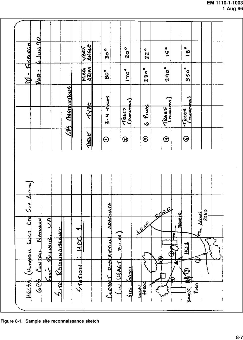
6 completion of a GPS survey. The site reconnaissance should ideally be completed before the survey is started. The surveyor should also prepare a site sketch and brief description on how to reach the point since the individual performing the site reconnaissance may not be the surveyor that returns to occupy the known or unknown station. (1) Project sketch. A project sketch should be developed before any site reconnaissance is performed. The sketch should be on a 7-1/2-min USGS quadrangle map or other suitable drawing. Drawing the sketch on the map will assist the planner in determination of site selections and travel distances between stations. (2) Station descriptions and recovery notes. Station descriptions for all new monuments will be developed as the monumentation is performed. The format of these descriptions will follow that stated in EM Recovery notes should be written for existing NGRS network stations and project control points, as detailed in EM Estimated travel times to all stations should be included in the description. Include road travel time, walking time, and GPS receiver breakdown and setup time. These times can be estimated while performing the initial reconnaissance. A site sketch shall also be made on the description/recovery form. Examples of site reconnaissance reports are shown in Figures 8-1 and 8-2. A blank reconnaissance report form is included as Worksheet 8-1 (Figure 8-3), which may be used in lieu of a standard field survey book. (3) Way point navigation. Way point navigation is an option on some receivers, allowing the user to enter geodetic position (usually latitude and longitude) of points of interest along a particular route the user may wish to follow. The GPS antenna, fastened to a vehicle or range pole, and receiver can then provide the user with navigational information. The navigational information may include the distance and bearing to the point of destination (stored in the receiver), the estimated time to destination, and the speed and course of the user. The resultant message produced can then be used to guide the user to the point of interest. Way point navigation is an option that, besides providing navigation information, may be helpful in the recovery of control stations which do not have descriptions. If the user has the capability of realtime code phase positioning, the way point navigational accuracy can be in the range of m. (4) Site obstruction/visibility sketches. The individual performing the site reconnaissance should record the azimuth and vertical angle of all obstructions. The azimuths and vertical angles should be determined with a compass and inclinometer. Because obstructions such as trees and buildings cause the GPS signal transmitted from the GPS satellite to be blocked, the type of obstruction is also an important item to be recorded, see Figure 8-2. The type of obstruction is also important to determine if multipath might cause a problem. Multipath is caused by the reflection of the GPS signal by a nearby object producing a false signal at the GPS antenna. Buildings with reflective surfaces, chain-link fences, and antenna arrays are objects that may cause multipath. The site obstruction data are needed to determine if the survey site is suitable for GPS surveying. Obstruction data should be plotted on a Station Visibility Diagram, as shown in Figure 8-4. (A blank copy of this form is provided as Worksheet 8-2 (Figure 8-5).) GPS surveying does require that all stations have an unobstructed view 15 deg above the horizon, and satellites below 10 deg should not be observed. (5) Suitability for kinematic observations. Clear, obstruction-free projects may be suitable for kinematic GPS surveys as opposed to static. The use of kinematic observations will increase productivity by a factor of 5 to 10 over static methods, while still providing adequate accuracy levels. On many projects, a mixture between both static and kinematic GPS observations may prove to be most cost-effective. (6) Monumentation. All monumentation should follow the guidelines of EM (7) On-site physical restrictions. The degree of difficulty in occupying points due to such factors as travel times, site access, multipath effects, and satellite visibility should be anticipated. The need for redundant observations, should reobservations be required, must also be considered. (8) Checks for disturbed existing control. Additional GPS baselines may need to be observed between existing NGRS/project control to verify their accuracy and/or stability. (9) Satellite visibility limitations. For most of the Continental United States, there are at least four to five satellites in view at all times. However, some areas may have less during times of satellite maintenance or unhealthy satellites. Satellite visibility charts of the GPS satellite constellation play a major part in optimizing network configurations and observation schedules. 8-6

7 Figure 8-1. Sample site reconnaissance sketch 8-7
8 Figure 8-2. Reconnaissance report on condition of survey 8-8

9 Figure 8-3. Worksheet 8-1, Site Reconnaissance Report form 8-9

10 Figure 8-4. Sample station visibility diagram 8-10

11 Figure 8-5. Worksheet 8-2, Station Visibility Diagram 8-11

12 (10) Station intervisibility requirements. Project specifications may dictate station intervisibility for azimuth reference. This may constrain minimum station spacing. f. Multiple/repeat baseline connections. Table 8-1 lists recommended criteria for baseline connections between stations, repeat baseline observations, and multiple station occupations. Many of these standards were developed by FGCS for performing high-precision geodetic control surveys such that extensive redundancy will result from the collected data. Since the purpose of these geodetic densification surveys is markedly different from USACE control densification, the need for such high observational redundancy is also different. Adding redundant baseline/station occupations may prove prudent on some remote projects where accessibility is difficult. g. Loop requirements. Loops (i.e., traverses) provide the mechanism for performing field data validation as well as final adjustment accuracy analysis. Since loops of GPS baselines are comparable to traditional EDM/taped traverse routes, misclosures and adjustments can be handled similarly. Most GPS survey nets (static or kinematic) end up with one or more interconnecting loops that are either internal from a single fixed point or external through two or more fixed network points. Loops should be closed off at the spacing indicated in Table 8-1. Loop closures should meet the criteria specified in Table 8-1, based on the total loop length. See also Chapter 10 for additional GPS loop closure checks. (1) GPS control surveys may be conducted by forming loops between two or more existing points, with adequate cross-connections where feasible. Such alignment procedures are usually most practical on civil works navigation projects which typically require control to be established along a linear path, e.g., river or canal embankments, levees, beach renourishment projects, and jetties. (2) Loops should be formed every 10 to 20 baselines, preferably closing on existing control. (3) Connections to existing control should be made as opportunities exist and/or as often as practical. (4) When establishing control over relatively large military installations, civil recreation projects, flood control projects, and the like, a series of redundant baselines forming interconnecting loops is usually recommended. When densifying Second- and Third-Order control for site plan design and construction, extensive cross-connecting loop and network configurations recommended by the FGCS for geodetic surveying are not necessary. (5) On all projects, maximum use of combined static and kinematic GPS observations should be considered, both of which may be configured to form pseudo-traverse loops for subsequent field data validation and final adjustment GPS Network Design and Layout A wide variety of survey configuration methods may be used to densify project control using GPS survey techniques. Unlike conventional triangulation, trilateration, and EDM traverse surveying, the shape, or geometry, of the GPS network design is not as significant. The following guidelines for planning and designing proposed GPS surveys are intended to support lower order (Second- Order, Class I, or 1:50,000 or less accuracy) control surveys applicable to USACE civil works and military construction activities. An exception to this would be GPS surveys supporting structural deformation monitoring projects where relative accuracies at the centimeter level or better are required over a small project area. a. Newly established GPS control may or may not be incorporated into the NGRS, depending on the adequacy of the connection to the existing NGRS network, or whether it was tied only internally to existing project control. b. Of paramount importance in developing a network design is to obtain the most economical coverage within the prescribed project accuracy requirements. The optimum network design, therefore, provides a minimum amount of baseline/loop redundancy without an unnecessary amount of over-observation. Obtaining this optimum design (cost versus accuracy) is difficult and constantly changing due to evolving GPS technology and satellite coverage. c. GPS survey layout schemes. The planning of a GPS survey scheme is similar to that for conventional triangulation or traversing. The type of survey design adopted is dependent on the GPS technique employed and the requirements of the user. (1) GPS networking. A GPS network is proposed when established survey control is to be used in precise network densification (1:50,000-1:100,000). For lower order work (i.e., less than 1:50,000), elaborate network schemes are unnecessary and less work-intensive GPS 8-12

13 survey extension methods may be used. When the networking method is selected, the surveyor should devise a survey network that is geometrically sound. Triangles that are weak geometrically should be avoided. The networking method is practical only with static, pseudokinematic, and kinematic survey techniques. Figure 8-6 shows an example of a step-by-step method to build a GPS survey network. azimuth targets are not visible, and a check angle cannot be observed, a closed traverse involving one or more control points is recommended. Again, a check angle or check azimuth should be observed from the starting control station. If a check angle is not performed, the survey can still be completed. However, if the survey does not meet specified closure requirements, the surveyor will be unable to assess what control point may be in error. If a check angle or check azimuth cannot be observed, a third control point should be tied into the traverse (Figure 8-7). This will aid in determining the cause of misclosure. Figure 8-6. GPS network design (2) GPS traversing. Traversing is the method of choice when the user has only two or three receivers and required accuracies are 1:5,000-1:50,000. Traversing with GPS is done similar to conventional methods. Open-end traverses are not recommended when 1:5,000 accuracies or greater are required. Since GPS does not provide sufficient point positioning accuracies, the surveyor must have a minimum of one fixed (or known) control point, although three are preferred. A fixed control point is a station with known latitude-longitude-height or eastingnorthing-height. This point may or may not be part of the NGRS. If only one control point is used and the station does not have a known height, the user will be unable to position the unknown stations. When performing a loop traverse, the surveyor should observe a check angle or check azimuth using conventional survey techniques to determine if the known station has been disturbed. If Figure 8-7. GPS traversing schemes (3) GPS spur shots. Spurs are an acceptable method when the user has only two receivers or only a few control points are to be established. Spur lines should be observed twice during two independent observing sessions. Once the first session is completed, the receivers at each station should be turned off and the tripod elevations changed. This procedure is similar to performing a forward and backward level line. It is important that the tripods be moved in elevation and replumbed over the control station between sessions. If this step is not implemented, the two baselines cannot be considered independent. Figure 8-8 shows an example of a spur line. Spurs are most applicable to static survey and relative positioning (code phase) techniques. 8-13

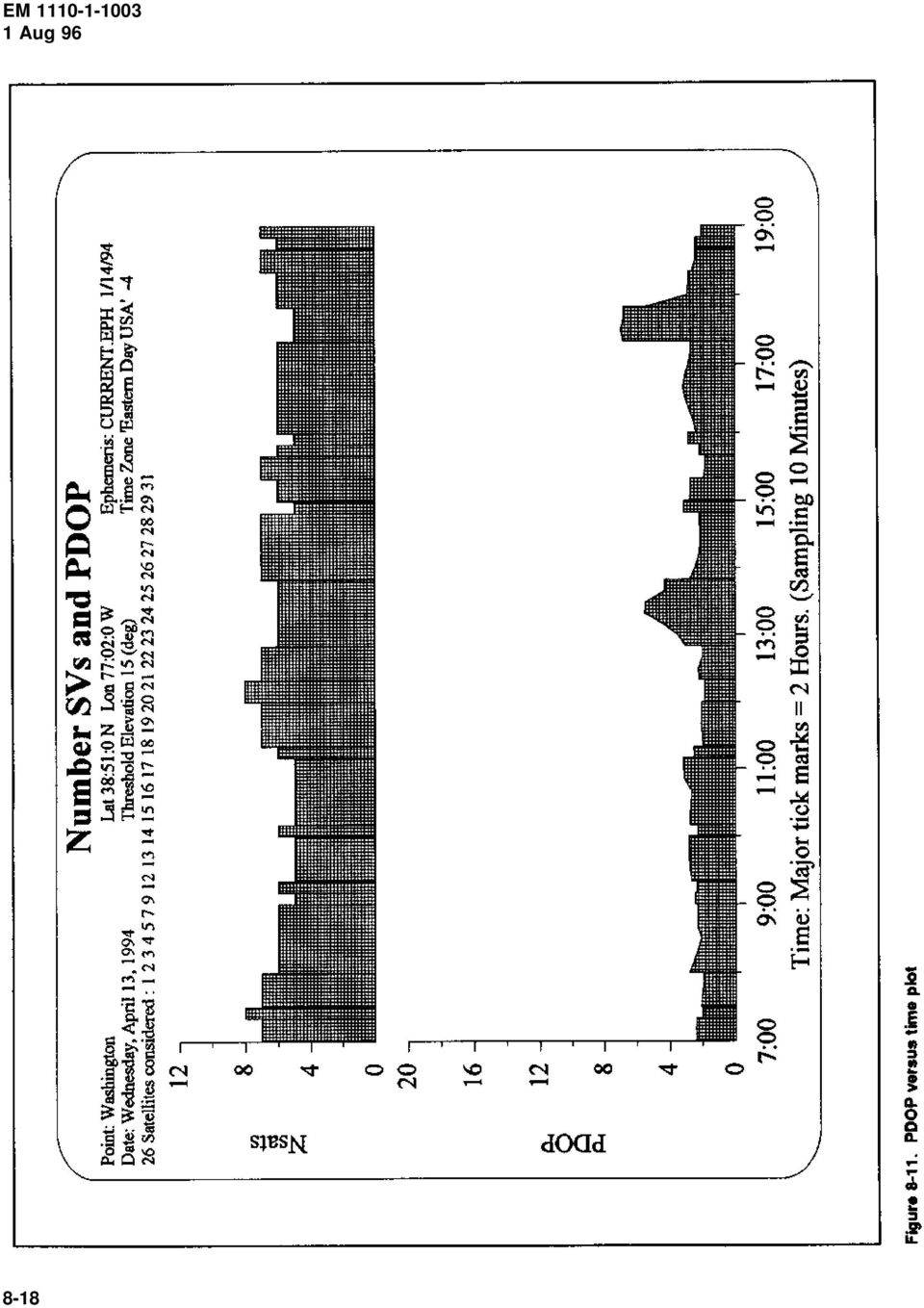
14 reference (set at known points) receivers and at least one rover are recommended. (2) Personnel. Personnel requirements are also project dependent. Most GPS equipment is compact and light weight and only requires one person per station setup. However, some cases where a station is not easily accessible or requires additional power for a data link, two individuals may be required. Figure 8-8. GPS spur line 8-5. GPS Techniques Needed for Survey After a GPS network has been designed and laid out, a GPS survey method or technique needs to be considered. The concepts for each method were discussed in Chapter 6 and the procedures are discussed in Chapter 9. The most efficient method should be chosen in order to minimize time and cost while meeting the accuracy requirements of a given survey project. Once a technique is chosen, the following can be set up: equipment requirements, observation schedules, and sessions designations and planning functions. a. General equipment requirements. The type of GPS instrumentation used on a project depends on the accuracy requirements of the project, GPS survey technique, project size, and economics. Most USACE projects can be completed using a single-frequency receiver. Dual-frequency receivers are recommended as baseline lengths approach or exceed 50 km. This length may also vary depending on the amount of solar activity during the observation period. Using a dual-frequency receiver permits the user to solve for possible ionospheric and tropospheric delays which can occur as the signal travels from the satellite to the receiver antenna. (1) Number of GPS receivers. The minimum number of receivers required to perform a differential GPS survey is two. The actual number used on a project will depend on the project size and number of available instruments/ operators. Using more than two receivers will often increase productivity and allow for more efficient field observations. For some kinematic applications, two (3) Transportation. One vehicle is normally required for each GPS receiver used on a project. This vehicle should be equipped to handle the physical conditions that may be encountered while performing the field observations. In most cases, a two-wheel-drive vehicle should be adequate for performing all field observations. If adverse site conditions exist, a four-wheel-drive vehicle may be required. Adequate and reliable transportation is important when the observation schedule requires moving from one station to another between observation sessions. (4) Auxiliary equipment. Adequate power should be available for all equipment (receivers, computers, lights, etc.) that will be used during the observations. Computers (386-based recommended), software, and data storage devices (floppy disks and/or cassette tapes) should be available for onsite field data reduction use. Other equipment required for conduct of a GPS survey should include tripods, tribrachs, measuring tapes, flagging, flashlights, tools, equipment cables, compass, and inclinometer. If real-time positioning is required, then a data link is also needed. b. Observation schedules. Planning a GPS survey requires that the surveyor determine when satellites will be visible for the given survey area; therefore, the first step in determining observation schedules is to plot a satellite visibility plot for the project area. Even when the GPS becomes fully operational, full 24-hr coverage of at least four satellites may not be available in all areas. (1) Most GPS manufacturers have software packages which at least predict satellite rise and set times. An excellent satellite plot will have the following essential information: satellite azimuths, elevations, set and rise times, and satellite PDOPs for the desired survey area. Satellite ephemeris data are generally required as input for the prediction software. (2) To obtain broadcast ephemeris information, a GPS receiver collects data during a satellite window. The receiver antenna does not have to be located over a 8-14

15 known point when collecting a broadcast ephemeris. The data are then downloaded to a personal computer where they are used as input into the software prediction program. Besides ephemeris data for the software, the user is generally required to enter approximate latitude and longitude (usually scaled from a topographic map) and time offset from UTC for the survey area. (3) From the satellite plot, the user can determine the best time to perform a successful GPS survey by taking advantage of the best combination of satellite azimuths, elevations, and PDOPs as determined by the satellite visibility plot for the desired survey area (for further information on favorable PDOP values, refer to Chapter 5). The number of sessions and/or stations per day depends on satellite visibility, travel times between stations, and the final accuracy of the survey. Often, a receiver is required to occupy a station for more than one session per day. (4) A satellite polar plot (Figure 8-9), a satellite azimuth and elevation table (Figure 8-10), and a PDOP versus time plot (Figure 8-11) may be run prior to site reconnaissance. The output files created by the satellite prediction software are used in determining if a site is suitable for GPS surveying. (5) Determination of session times is based mainly on the satellite visibility plan with the following factors taken into consideration: time required to permit safe travel between survey sites; time to set up and take down the equipment before and after the survey; time of survey; and possible time loss due to unforeseeable problems or complications. Station occupation during each session should be designed to minimize travel time in order to maximize the overall efficiency of the survey. c. Session designations and planning functions. A survey session in GPS terminology refers to a single period of observation. Sessions and station designations are usually denoted by alphanumeric characters (0, 1, 2, A, B, C, etc.), determined prior to survey commencement. (1) When only eight numeric characters are permitted for station/session designations, the following convention may be followed: where = type of monument with the following convention being recommended: 1 = known horizontal control monument 2 = known benchmark 3 = known 3D monument 4 = new horizontal control monument 5 = new benchmark 6 = new 3D monument 7 = unplanned occupation 8 = temporary 2D point 9 = temporary 3D point 2, 3, 4 = actual station number given to each station 5, 6, 7 = Julian day of year 8 = session number (a) Example: Station Identifier: Position: (b) The numeral 4 in the number 1 position indicates the monument being established is a new monument where only horizontal position is being established. (c) The 001 in the number 2, 3, and 4 position is the station number that has been given to the monument for this project. (d) The 182 in the number 5, 6, and 7 position is the Julian day of the year. This is the same day as 1 July. (e) The numeral 1 in the number 8 position identifies the session number during which observations are being made. If the receiver performed observations during the second session on the same day on the same monument, the session number should be changed to 2 for the period of the second session (then the total station identifier would be ). (2) When alpha characters are permitted for station/ session designation, then a more meaningful designation can be assigned to the designation. The date of each survey session should be recorded during the survey as calendar dates and Julian days and used in the station/session designation. Some GPS software programs will require Julian dates for correct software operation. In addition to determination of station/session designations before the survey begins, the user (usually the crew chief) must: (a) Determine the occupant of each station. (b) Determine satellite visibility for each station. 8-15
.")
16 8-16

17 Figure Satellite azimuth and elevation table 8-17

18 8-18
19 (c) Require site reconnaissance data for stations to be occupied. Remember the same person who performed the initial site reconnaissance may not be the individual performing the survey; therefore, prior determined site reconnaissance data may require clarification before survey commencement. (f) Require a station data logging sheet completed for each station. Figures 8-12 and 8-13 are examples of various station logs used in USACE, along with blank forms which may be used as worksheets. Standard bound field survey books may be used in lieu of separate log/work sheets. (d) Develop a project sketch. (e) Issue explicit instructions on when each session is to begin and end. 8-19

20 Figure Sample GPS data logging sheet (Continued) 8-20

21 Figure (Concluded) 8-21
22 Figure Worksheet 8-3, GPS data logging sheet (Continued) 8-22
23 Figure (Concluded) 8-23
SURVEYING WITH GPS. GPS has become a standard surveying technique in most surveying practices
 SURVEYING WITH GPS Key Words: Static, Fast-static, Kinematic, Pseudo- Kinematic, Real-time kinematic, Receiver Initialization, On The Fly (OTF), Baselines, Redundant baselines, Base Receiver, Rover GPS
4.03 Vertical Control Surveys: 4-1
 4. HORIZONTAL AND VERTICAL CONTROL 4.01 General: Sufficient horizontal and, if applicable, vertical control surveys shall be established by the Contractor for all photogrammetric mapping purposes. Prior
Chapter 11 Adjustment of GPS Surveys
 Chapter 11 Adjustment of GPS Surveys 11-1. General Differential carrier phase GPS survey observations are adjusted no differently from conventional surveys. Each three-dimensional GPS baseline vector is
Earth Coordinates & Grid Coordinate Systems
 Earth Coordinates & Grid Coordinate Systems How do we model the earth? Datums Datums mathematically describe the surface of the Earth. Accounts for mean sea level, topography, and gravity models. Projections
GNSS and Heighting, Practical Considerations. A Parker National Geo-spatial Information Department of Rural Development and Land Reform
 GNSS and Heighting, Practical Considerations A Parker National Geo-spatial Information Department of Rural Development and Land Reform GNSS Global Navigation Satellite Systems (GNSS) Global Positioning
Survey Ties Guidelines
 North Carolina Board of Examiners for Engineers and Surveyors Survey Ties Guidelines The North Carolina Board of Examiners for Engineers and Surveyors is providing this document to serve as an interpretative
CHAPTER 9 SURVEYING TERMS AND ABBREVIATIONS
 CHAPTER 9 SURVEYING TERMS AND ABBREVIATIONS Surveying Terms 9-2 Standard Abbreviations 9-6 9-1 A) SURVEYING TERMS Accuracy - The degree of conformity with a standard, or the degree of perfection attained
NJDEP GPS Data Collection Standards For GIS Data Development
 NJDEP GPS Data Collection Standards For GIS Data Development Bureau of Geographic Information Systems Office of Information Resource Management June 8, 2011 1.0 Introduction... 3 2.0 GPS Receiver Hardware
The Map Grid of Australia 1994 A Simplified Computational Manual
 The Map Grid of Australia 1994 A Simplified Computational Manual The Map Grid of Australia 1994 A Simplified Computational Manual 'What's the good of Mercator's North Poles and Equators, Tropics, Zones
Trimble R8 Base and Rover Quick Setup Guide. Inland GPS Inc.
 Trimble R8 Base and Rover Quick Setup Guide Inland GPS Inc. Setting up the GPS Base Equipment Hardware First Find the best, most advantageous secure place to setup the GPS base equipment. Look for a high
TI GPS PPS Timing Application Note
 Application Note Version 0.6 January 2012 1 Contents Table of Contents 1 INTRODUCTION... 3 2 1PPS CHARACTERISTICS... 3 3 TEST SETUP... 4 4 PPS TEST RESULTS... 6 Figures Figure 1 - Simplified GPS Receiver
CHAPTER 3 PROJECT CONTROL
 CHAPTER 3 PROJECT CONTROL Marking Survey Control Points 3-2 Horizontal Control 3-2 Vertical Control 3-3 Preconstruction Bench Marks 3-3 Bench Mark Levels 3-3 Bench Mark Check Levels 3-5 Total Station Leveling
Guidelines for RTK/RTN GNSS Surveying in Canada
 Guidelines for RTK/RTN GNSS Surveying in Canada July 2013 Version 1.1 Ministry of Transportation Ministère des Transports EARTH SCIENCES SECTOR GENERAL INFORMATION PRODUCT 100-E Main Authors: Brian Donahue,
Global Positioning System
 B. Hofmann-Wellenhof, H. Lichtenegger, and J. Collins Global Positioning System Theory and Practice Third, revised edition Springer-Verlag Wien New York Contents Abbreviations Numerical constants xix xxiii
Geospatial Positioning Accuracy Standards Part 2: Standards for Geodetic Networks
 Geospatial Positioning Accuracy Standards Federal Geodetic Control Subcommittee Federal Geographic Data Committee Federal Geographic Data Committee Department of Agriculture Department of Commerce Department
GPS Data Collection Procedures for Georeferencing Vegetation Resources Inventory and National Forest Inventory Field Sample Plots
 Province of British Columbia GPS Data Collection Procedures for Georeferencing Vegetation Resources Inventory and National Forest Inventory Field Sample Plots Resources Information Branch Ministry of Sustainable
Model Virginia Map Accuracy Standards Guideline
 Commonwealth of Virginia Model Virginia Map Accuracy Standards Guideline Virginia Information Technologies Agency (VITA) Publication Version Control Publication Version Control: It is the user's responsibility
www.passpe.com Surveying for California Civil PE License Dr. Shahin A. Mansour, PE Surveying for California Civil Engineering License
 Well Organized, Based on the Current California Board Test Plan and References, Detailed, Computer Generated Index (8 pages), Simplified Concepts, 66 Sample Problems with Detailed Solutions, and 181 Supplemental
Leica SmartNet UK & Ireland Network RTK User Guide
 Leica SmartNet UK & Ireland Network RTK User Guide Contents Background.. Page 3 Single Base RTK.... Page 3 Advantages & Disadvantages of Single Base RTK Page 4 Network RTK... Page 4 Advantages & Disadvantages
PLOTTING SURVEYING DATA IN GOOGLE EARTH
 PLOTTING SURVEYING DATA IN GOOGLE EARTH D M STILLMAN Abstract Detail surveys measured with a total station use local coordinate systems. To make the data obtained from such surveys compatible with Google
Total Program's Units
 Associate Degree Program Department of Civil and Architectural Technology Major : Survey Technology First Semester NO 5 6 Code SRV 0 SRV 0 SRV 0 ENG 0 MTH 7 CMT 0 Course Title Land survey Survey drawing
SURVEY PRO. GPS Quick Start Guide
 SURVEY PRO GPS Quick Start Guide ii Table of Contents Before You Leave the Office...1 Survey Method: RTK or Post Processing...2 Receiver Setup...2 Receiver Settings...3 RTK Data Collection and Stake Out...4
Learning about GPS and GIS
 Learning about GPS and GIS Standards 4.4 Understand geographic information systems (G.I.S.). B12.1 Understand common surveying techniques used in agriculture (e.g., leveling, land measurement, building
Post Processing Service
 Post Processing Service The delay of propagation of the signal due to the ionosphere is the main source of generation of positioning errors. This problem can be bypassed using a dual-frequency receivers
Maps A Primer for Content & Production of Topographic Base Maps For Design Presented by SurvBase, LLC
 Maps A Primer for Content & Production of Topographic Base Maps For Design Presented by Definition and Purpose of, Map: a representation of the whole or a part of an area. Maps serve a wide range of purposes.
WHAT YOU NEED TO USE THE STATE PLANE COORDINATE SYSTEMS
 WHAT YOU NEED TO USE THE STATE PLANE COORDINATE SYSTEMS N & E State Plane Coordinates for Control Points AZIMUTHS - True, Geodetic, or Grid - Conversion from Astronomic to Geodetic (LaPlace Correction)
Luce Bayou, Armand Bayou, Cedar Bayou, Clear Creek, Jackson Bayou, San Jacinto River, Galveston and Spring Gully/Goose Creek
 Luce Bayou, Armand Bayou, Cedar Bayou, Clear Creek, Jackson Bayou, San Jacinto River, Galveston and Spring Gully/Goose Creek Prepared by: Professional Surveyors 1702 Seamist Drive, Suite 320 Houston, TX
GEOGRAPHIC INFORMATION SYSTEMS Lecture 21: The Global Positioning System
 GEOGRAPHIC INFORMATION SYSTEMS Lecture 21: The Global Positioning System The Global Positioning System - recognize that GPS is only one of several Global Navigation Satellite Systems (GNSS) - the Russian
{ XE "CIR_30-6_intelligent_compaction_D02-26-14" } Page 1 of 10
 { XE "CIR_30-6_intelligent_compaction_D02-26-14" } Page 1 of 10 Section 30-6. Use to incorporate intelligent compaction requirements in CIR or FDR projects. Use bid item: 306100A Intelligent Compaction
UNITED NATIONS E/CONF.97/5/CRP. 13
 UNITED NATIONS E/CONF.97/5/CRP. 13 ECONOMIC AND SOCIAL COUNCIL Seventeenth United Nations Regional Cartographic Conference for Asia and the Pacific Bangkok, 18-22 September 2006 Item 6 (b) of the provisional
STATE OF ALASKA DEPARTMENT OF NATURAL RESOURCES DIVISION OF MINING, LAND AND WATER. GENERAL SURVEY INSTRUCTIONS EASEMENTS Authority 11 AAC 53
 STATE OF ALASKA DEPARTMENT OF NATURAL RESOURCES DIVISION OF MINING, LAND AND WATER GENERAL SURVEY INSTRUCTIONS EASEMENTS Authority 11 AAC 53 These instructions define the survey and platting criteria unique
Request for Proposals for Topographic Mapping. Issued by: Teton County GIS and Teton County Engineering Teton County, Wyoming
 Request for Proposals for Topographic Mapping Issued by: Teton County GIS and Teton County Engineering Teton County, Wyoming Proposals due: 2:00PM MDT July 1, 2015 Proposals may be delivered to: Teton
Survey Field Note Standards
 OREGON DEPARTMENT OF TRANSPORTATION 200 Hawthorne Avenue S.E. Suite B250 Salem, OR 97310 (503) 986-3103 Ron Singh, PLS Chief of Surveys (503) 986-3033 Survey Technical Advisory Committee David Artman,
GPS: A Primer. presented by Jim Pugh, GISP GIS Project Manager. 2007, EMH&T, Inc.
 GPS: A Primer presented by Jim Pugh, GISP GIS Project Manager GPS: A Primer GPS = Global Positioning System 24 Satellites in Orbit around Earth Each Broadcasts precise time and known location Receivers
Analysis of RTN Measurement Results Referring to ASG-EUPOS Network
 GEOMATICS AND ENVIRONMENTAL ENGINEERING Volume 4 Number 1/1 2010 Andrzej Uznañski* Analysis of RTN Measurement Results Referring to ASG-EUPOS Network 1. Introduction In June 2008 ASG-EUPOS network system,
GPS LOCATIONS FOR GIS: GETTING THEM RIGHT THE FIRST TIME
 GPS LOCATIONS FOR GIS: GETTING THEM RIGHT THE FIRST TIME Caroline Erickson and Pierre Héroux Geodetic Survey Division, Geomatics Canada Natural Resources Canada 615 Booth Street Ottawa, Ontario K1A 0E9
ELEMENTS OF SURVEYING FOR CADASTRAL MAPPING
 ELEMENTS OF SURVEYING FOR CADASTRAL MAPPING Chapter 4 2015 Cadastral Mapping Manual 4-0 Elements of Surveying and Mapping Utah's system of land surveying is the rectangular survey system as set forth on
A comparison of radio direction-finding technologies. Paul Denisowski, Applications Engineer Rohde & Schwarz
 A comparison of radio direction-finding technologies Paul Denisowski, Applications Engineer Rohde & Schwarz Topics General introduction to radiolocation Manual DF techniques Doppler DF Time difference
MINIMUM STANDARDS OF ACCURACY, CONTENT AND CERTIFICATION FOR SURVEYS AND MAPS ARTICLE I. TYPES OF SURVEYS
 MINIMUM STANDARDS OF ACCURACY, CONTENT AND CERTIFICATION FOR SURVEYS AND MAPS ARTICLE I. TYPES OF SURVEYS Current with material published in Conn.L.J. through 5/13/08 Sec. 20-300b-1. General There are
Post Processing GPS raw observations using data obtained from Continuously Operating Reference Stations (CORS)
") Post Processing GPS raw observations using data obtained from Continuously Operating Reference Stations (CORS) This guide is written using Leica Geo Office version 4, with base and rover data from a Leica
Post Processing GPS raw observations using data obtained from Continuously Operating Reference Stations (CORS) This guide is written using Leica Geo Office version 4, with base and rover data from a Leica
CHAPTER 7 TRAVERSE Section I. SELECTION OF TRAVERSE DEFINITION
 CHAPTER 7 TRAVERSE Section I. SELECTION OF TRAVERSE DEFINITION A traverse is a series of straight lines called traverse legs. The surveyor uses them to connect a series of selected points called traverse
TECHNICAL REPORT NO. 49 BIDIRECTIONAL TRANSFORMATION OF LEGACY AND CURRENT SURVEY CONTROL DATA WITHIN SOUTHEASTERN WISCONSIN
 TECHNICAL REPORT NO. 49 BIDIRECTIONAL TRANSFORMATION OF LEGACY AND CURRENT SURVEY CONTROL DATA WITHIN SOUTHEASTERN WISCONSIN SOUTHEASTERN WISCONSIN REGIONAL PLANNING COMMISSION SOUTHEASTERN WISCONSIN REGIONAL
Lecture 2. Map Projections and GIS Coordinate Systems. Tomislav Sapic GIS Technologist Faculty of Natural Resources Management Lakehead University
 Lecture 2 Map Projections and GIS Coordinate Systems Tomislav Sapic GIS Technologist Faculty of Natural Resources Management Lakehead University Map Projections Map projections are mathematical formulas
NSPS SURVEY TECHNICIAN CERTIFICATION PROGRAM LEVEL III SAMPLE EXAMINATION QUESTIONS
 NSPS SURVEY TECHNICIAN CERTIFICATION PROGRAM LEVEL III SAMPLE EXAMINATION QUESTIONS NATIONAL SOCIETY OF PROFESSIONAL SURVEYORS October 2007 This booklet has been prepared to provide an example of what
Submitted to: Submitted by: Department of Geology and Mineral Industries 800 NE Oregon Street, Suite 965 Portland, OR 97232
 LIDAR REMOTE SENSING DATA COLLECTION DEPARTMENT OF F GEOLOGY AND MINERAL INDUSTRIES CRATER LAKE, OREGON NOVEMBER 30, 2010 Submitted to: Department of Geology and Mineral Industries 800 NE Oregon Street,
Geographic Referencing
 CHAPTER 10 Geographic Referencing 10.1 GEOGRAPHIC LOCATION SYSTEMS To create a reliable map, it is necessary to relate the digital data to its true terrestrial situation. 10.1.1 Land Subdivision The system
Prof. Ludovico Biagi. Satellite Navigation and Monitoring
 Prof. Ludovico Biagi Satellite Navigation and Monitoring Navigation: trajectories control positions estimations in real time, at high frequency popular applications: low accuracy (10 m) required specific
Trimble CenterPoint RTX Post-Processing Services FAQs
 Trimble CenterPoint RTX Post-Processing Services FAQs What is Trimble RTX technology? 30 September 2013 Trimble RTX TM (Real Time extended) is a high-accuracy, global GNSS correction technology that combines
GPS Positioning Modes
 5 GPS Positioning Modes Positioning with GPS can be performed in either of two ways: point (absolute) positioning or relative positioning. Classical GPS point positioning employs one GPS receiver that
STATE CONTROL SURVEY SPECIFICATIONS FOR PRIMARY CONTROL SURVEYS. Now Obsolete
 STATE CONTROL SURVEY SPECIFICATIONS FOR PRIMARY CONTROL SURVEYS Now Obsolete Caution: This document has been prepared by scanning the original Specifications for Primary Control Surveys - 1984 and using
4 The Rhumb Line and the Great Circle in Navigation
 4 The Rhumb Line and the Great Circle in Navigation 4.1 Details on Great Circles In fig. GN 4.1 two Great Circle/Rhumb Line cases are shown, one in each hemisphere. In each case the shorter distance between
GPS accuracy: Hand-held versus RTK
 GPS accuracy GPS accuracy: Hand-held versus RTK Kevin W. Hall, Joanna K. Cooper, and Don C. Lawton ABSTRACT Source and receiver points for seismic lines recorded during the geophysics field school near
1. We assume the mentioned inaccuracies refer to the at least one foot in ten thousand standard described in point three.
 RFQ GIS Parcel Boundary Correction Services BD 2015-035 Questions and Answers December 31st December 10 th 1. We assume the mentioned inaccuracies refer to the at least one foot in ten thousand standard
GPS Data Collection Guidelines
 GPS Data Collection Guidelines Prepared by the Standards & Data Coordination Work Group of the NYS GIS Coordination Program Last Updated: April 2007 1 Executive Summary Purpose The goal of this document
CHAPTER 8 - LAND DESCRIPTIONS
 CHAPTER 8 - LAND DESCRIPTIONS Notes: While the location of land is commonly referred to by street number and city, it is necessary to use the legal description in the preparation of those instruments relating
Railway Track Deformation Surveying Using GNSS Real and Virtual Reference
 85 Railway Track Deformation Surveying Using GNSS Real and Virtual Reference Švábenský, O. 1, Plášek, O. 2 and Bureš, J. 1 1 Brno University of Technology, Faculty of Civil Engineering, Institute of Geodesy,
Field/Lab Exercise 2 Surveying Offsets and Handheld Survey Tools
 Field/Lab Exercise 2 Surveying Offsets and Handheld Survey Tools Field Data Goal of this Exercise: to explore surveying methods as offsets from GPS points. Background: Cartesian and Polar Coordinates,
Real-Time Kinematic Surveying
 Real-Time Kinematic Surveying Training Guide F Part Number 33142-40 Revision D September 2003 Corporate Office Trimble Navigation Limited 645 North Mary Avenue Post Office Box 3642 Sunnyvale, CA 94088-3642
Total Station Setup and Operation. Sokkia SET Total Station
 Total Station Setup and Operation Sokkia SET Total Station Parts of the SET Total Station Parts of the SET Total Station Sokkia SET 550 Total Station Keys/Screen SET 550 Menu Pages SET 550 Menu Pages Leveling
Enabling RTK-like positioning offshore using the global VERIPOS GNSS network. Pieter Toor GNSS Technology Manager
 Enabling RTK-like positioning offshore using the global VERIPOS GNSS network Pieter Toor GNSS Technology Manager Introduction PPP/RTK Positioning Techniques PPP-AR Technology Presentation Overview PPP-AR
Subdivision Mapping: Making the Pieces Fit David P. Thaler, GIS Analyst A geographit White Paper, June 2009
 Subdivision Mapping: Making the Pieces Fit P David P. Thaler, GIS Analyst A geographit White Paper, June 2009 1525 Oregon Pike, Suite 202 Lancaster, PA USA 17601-7300 Phone: 717-399-7007 Fax: 717-399-7015
ROAD SURVEYING Section I. RECONNAISSANCE SURVEY PREPARATION AND SCOPE
 CHAPTER 2 ROAD SURVEYING Section I. RECONNAISSANCE SURVEY PREPARATION AND SCOPE The reconnaissance survey is an extensive study of an entire area that might be used for a road or airfield. Its purpose
Brevard County Public Works Finance and Contracts Administration
 Brevard County Public Works Finance and Contracts Administration Public Works Survey & Mapping Division Review Check Sheet for Land Acquisition, Drainage, Roadway and Pedway Expansion, Asbuilts, Maintenance
UTM Zones for the US UTM UTM. Uniform strips Scalable coordinates
 UTM UTM Uniform strips Scalable coordinates Globally consistent, most popular projection/coordinate system for regional to global scale geospatial data (i.e. satellite images global scale datasets USGS/EDC)
Greg Keel P.Eng. Parallel Geo Services gkeel@nanaimo.ark.com
 Greg Keel P.Eng. Parallel Geo Services gkeel@nanaimo.ark.com Presentation Outline GNSS: Global Navigation Satellite System GPS: overview, current signals, modernization GLONASS: history (rise fall rise),
The Applanix SmartBase TM Software for Improved Robustness, Accuracy, and Productivity of Mobile Mapping and Positioning
 The Applanix SmartBase TM Software for Improved Robustness, Accuracy, and Productivity of Mobile Mapping and Positioning Joe Hutton and Edith Roy, Applanix Corporation Introduction Applanix, along with
Little Lake Shoreline Protection & Marsh Creation Project BA-37
 Little Lake Shoreline Protection & Marsh Creation Project BA-37 SCI PROJECT NO. 116478 POST CONSTRUCTION SURVEY REPORT AUGUST 2007 Prepared for: Louisiana Department of Natural Resources Prepared By: Shaw
Selecting Receiving Antennas for Radio Tracking
 Selecting Receiving Antennas for Radio Tracking Larry B Kuechle, Advanced Telemetry Systems, Inc. Isanti, Minnesota 55040 lkuechle@atstrack.com The receiving antenna is an integral part of any radio location
CHAPTER 4 LEGAL DESCRIPTION OF LAND DESCRIBING LAND METHODS OF DESCRIBING REAL ESTATE
 r CHAPTER 4 LEGAL DESCRIPTION OF LAND DESCRIBING LAND A legal description is a detailed way of describing a parcel of land for documents such as deeds and mortgages that will be accepted in a court of
A GPS Digital Phased Array Antenna and Receiver
 A GPS Digital Phased Array Antenna and Receiver Dr. Alison Brown, Randy Silva; NAVSYS Corporation ABSTRACT NAVSYS High Gain Advanced GPS Receiver (HAGR) uses a digital beam-steering antenna array to enable
Leica GNSS Reference Antennas White Paper
 Leica GNSS Reference Antennas White Paper State of The Art, Leading Edge Geodetic Antennas from Leica Geosystems Justin Walford, Leica Geosystems BIOGRAPHY Justin Walford holds an M.Sc.E in Survey Engineering
GENERAL INFORMATION ON GNSS AUGMENTATION SYSTEMS
 GENERAL INFORMATION ON GNSS AUGMENTATION SYSTEMS 1. INTRODUCTION Navigation technologies with precision approach and landing systems, for civilian and military purposes, enable aircrafts to perform their
Günter Seeber. Satellite Geodesy 2nd completely revised and extended edition
 Günter Seeber Satellite Geodesy 2nd completely revised and extended edition Walter de Gruyter Berlin New York 2003 Contents Preface Abbreviations vii xvii 1 Introduction 1 1.1 Subject of Satellite Geodesy...
Accuracy of Geometric Geoid Model of Singapore using RTK Heighting
 Yam Khoon TOR, Singapore Key words: Geometric Geoid, RTK Heighting SUMMARY A complete re-levelling of the precise levelling network of Singapore was carried out to derive the reduced levels of some 2000
Case Study Australia. Dr John Dawson A/g Branch Head Geodesy and Seismic Monitoring Geoscience Australia. Chair UN-GGIM-AP WG1 Chair APREF.
 Case Study Australia Dr John Dawson A/g Branch Head Geodesy and Seismic Monitoring Geoscience Australia Chair UN-GGIM-AP WG1 Chair APREF Page 1 Overview 1. Australian height system Australian Height Datum
EPSG. Coordinate Reference System Definition - Recommended Practice. Guidance Note Number 5
 European Petroleum Survey Group EPSG Guidance Note Number 5 Coordinate Reference System Definition - Recommended Practice Revision history: Version Date Amendments 1.0 April 1997 First release. 1.1 June
National Register of Historic Places: GIS Webinar Cultural Resource GIS Facility National Park Service June 2012
 National Register of Historic Places: GIS Webinar Cultural Resource GIS Facility National Park Service June 2012 In February and March 2012 the National Register of Historic Places held webinars in conjunction
North American Horizontal Datums. Jan Van Sickle
 North American Horizontal Datums Jan Van Sickle http://www.holoscenes.com/cgi-bin/moin.cgi/easternobliquearc The New England Datum 1879 was the first geodetic datum of this type in the United States. The
MINIMUM STANDARDS FOR ACCEPTANCE OF AQUATIC RESOURCES DELINEATION REPORTS
 MINIMUM STANDARDS FOR ACCEPTANCE OF AQUATIC RESOURCES DELINEATION REPORTS U.S. ARMY CORPS OF ENGINEERS BUILDING STRONG January 2016 The U.S Army Corps of Engineers, through its Regulatory Program, regulates
Geospatial Positioning Accuracy Standards Part 3: National Standard for Spatial Data Accuracy
 Subcommittee for Base Cartographic Data Federal Geographic Data Committee Federal Geographic Data Committee Department of Agriculture Department of Commerce Department of Defense Department of Energy Department
Cost and Accuracy Analysis of Detail Measurements by Real-Time Kinematic GPS (RTK-GPS)
") Cost and Accuracy Analysis of Detail Measurements by Real-Time Kinematic GPS (RTK-GPS) Dr.Ayhan CEYLAN, Dr. Omer MUTLUOGLU and C. Ozer YIGIT, Turkey Key words: Detail measurement, RTK-GPS, Electronic Tacheometry.
Cost and Accuracy Analysis of Detail Measurements by Real-Time Kinematic GPS (RTK-GPS) Dr.Ayhan CEYLAN, Dr. Omer MUTLUOGLU and C. Ozer YIGIT, Turkey Key words: Detail measurement, RTK-GPS, Electronic Tacheometry.
EXPERIMENTS IN THE DEVELOPMENT OF THE HUNGARIAN GPS NETWORKS
 III. Évfolyam 1. szám - 2008. március Koós Tamás Zrínyi Miklós Nemzetvédelmi Egyetem koos.tamas@zmne.hu EXPERIMENTS IN THE DEVELOPMENT OF THE HUNGARIAN GPS NETWORKS Abstract The establishment of the GPS
1 Basic concepts of surveying
 1 Basic concepts of surveying The aim of this chapter is to introduce the reader to the basic concepts of surveying. It is therefore the most important chapter and worthy of careful study and consideration.
A Novel GPS Survey Antenna
 A Novel GPS Survey Antenna Waldemar Kunysz, NovAtel Inc. BIOGRAPHY Waldemar Kunysz obtained a BSEE from the Technical University of Nova Scotia in 1989. From 1991 to 1995 he worked on phased array antennas
Development of new hybrid geoid model for Japan, GSIGEO2011. Basara MIYAHARA, Tokuro KODAMA, Yuki KUROISHI
 Development of new hybrid geoid model for Japan, GSIGEO2011 11 Development of new hybrid geoid model for Japan, GSIGEO2011 Basara MIYAHARA, Tokuro KODAMA, Yuki KUROISHI (Published online: 26 December 2014)
GLOBAL POSITIONING SYSTEM IN TRANSPORTATION PLANNING
 GLOBAL POSITIONING SYSTEM IN TRANSPORTATION PLANNING N.Thilagavathi and G.N.Mallikarjuna Rao Sona College of Technology Salem KEY WORDS:. 1. INTRODUCTION Global Positioning System, a worldwide satellite
GNSS FIELD DATA COLLECTION GUIDELINES
 AD-SDI DATA STANDARD GNSS FIELD DATA COLLECTION GUIDELINES Version 1.0 September 2011 Prepared by Abu Dhabi Spatial Data Infrastructure (AD-SDI) Abu Dhabi Systems and Information Centre (ADSIC) Abu Dhabi,
Stream Channel Cross Sections for a Reach of the Boise River in Ada County, Idaho
 U.S. Department of the Interior U.S. Geological Survey In cooperation with Federal Emergency Management Agency, City of Boise, City of Garden City, City of Eagle, and Ada County Stream Channel Cross Sections
PARAMETRIC MODELING. David Rosen. December 1997. By carefully laying-out datums and geometry, then constraining them with dimensions and constraints,
 1 of 5 11/18/2004 6:24 PM PARAMETRIC MODELING David Rosen December 1997 The term parametric modeling denotes the use of parameters to control the dimensions and shape of CAD models. Think of a rubber CAD
INTEGRITY AND CONTINUITY ANALYSIS OCTOBER TO DECEMBER 2013 QUARTERLY REPORT FROM GPS. Integrity and Continuity Analysis 08/01/14 08/01/14 08/01/14
 INTEGRITY AND CONTINUITY ANALYSIS FROM GPS OCTOBER TO DECEMBER 2013 QUARTERLY REPORT Prepared by: M Pattinson (NSL) 08/01/14 Checked by: L Banfield (NSL) 08/01/14 Approved by: M Dumville (NSL) 08/01/14
GPS Receiver Test. Conducted by the Department of Mathematical Geodesy and Positioning Delft University of Technology
 GPS Receiver Test Conducted by the Department of Mathematical Geodesy and Positioning Delft University of Technology A. Amiri-Simkooei R. Kremers C. Tiberius May 24 Preface For the purpose of a receiver
ESTABLISHMENT OF A PERMANENT GPS STATION AT THE DEPARTMENT OF GEODESY AND SURVEYING OF THE BUDAPEST UNIVERSITY OF TECHNOLOGY AND ECONOMICS
 PERIODICA POLYTECHNICA SER. CIV. ENG. VOL. 46, NO. 2, PP. 179 184 (2002) ESTABLISHMENT OF A PERMANENT GPS STATION AT THE DEPARTMENT OF GEODESY AND SURVEYING OF THE BUDAPEST UNIVERSITY OF TECHNOLOGY AND
Weed Survey and Mapping
 Weed Survey and Mapping The primary objective of weed surveying and mapping is to accurately identify and delineate land with populations of invasive plants or noxious weeds. These surveys allow land managers
WMATA S Automated Track Analysis Technology & Data Leveraging for Maintenance Decisions
 WMATA S Automated Track Analysis Technology & Data Leveraging for Maintenance Decisions 1 WMATA System 6 Lines: 5 radial and 1 spur 234 mainline track miles and 91 stations Crew of 54 Track Inspectors
IT Service Management
 IT Service Management Service Continuity Methods (Disaster Recovery Planning) White Paper Prepared by: Rick Leopoldi May 25, 2002 Copyright 2001. All rights reserved. Duplication of this document or extraction
Introduction to GIS (Basics, Data, Analysis) & Case Studies. 13 th May 2004. Content. What is GIS?
 & Case Studies. 13 th May 2004. Content. What is GIS?") Introduction to GIS (Basics, Data, Analysis) & Case Studies 13 th May 2004 Content Introduction to GIS Data concepts Data input Analysis Applications selected examples What is GIS? Geographic Information
Introduction to GIS (Basics, Data, Analysis) & Case Studies 13 th May 2004 Content Introduction to GIS Data concepts Data input Analysis Applications selected examples What is GIS? Geographic Information
Online Precise Point Positioning Using the. Natural Resources Canada Canadian Spatial Reference System (CSRS-PPP)
") Online Precise Point Positioning Using the Natural Resources Canada Canadian Spatial Reference System (CSRS-PPP) Thomas Nylen and Seth White UNAVCO October 2007 I. Precise Point Positioning Precise Point
Online Precise Point Positioning Using the Natural Resources Canada Canadian Spatial Reference System (CSRS-PPP) Thomas Nylen and Seth White UNAVCO October 2007 I. Precise Point Positioning Precise Point
Coordinate Systems. Orbits and Rotation
 Coordinate Systems Orbits and Rotation Earth orbit. The earth s orbit around the sun is nearly circular but not quite. It s actually an ellipse whose average distance from the sun is one AU (150 million
How To Use Gss Software In Trimble Business Center
 Trimble Business Center software technical notes Trimble Business Center Software Makes Processing GNSS Survey Data Effortless Trimble Business Center is powerful surveying office software designed to
Maximizing Throughput and Coverage for Wi Fi and Cellular
 Maximizing Throughput and Coverage for Wi Fi and Cellular A White Paper Prepared by Sebastian Rowson, Ph.D. Chief Scientist, Ethertronics, Inc. www.ethertronics.com March 2012 Introduction Ask consumers