Table of Contents. XXII. Motorized Scuttles & fire Vents
|
|
|
- Junior Lindsey
- 7 years ago
- Views:
Transcription
1 Table of Contents XXII. Motorized Scuttles & fire Vents 1. General Notes 2. SV - Single Leaf 3. SV - Double Leaf (Profile) 4. SV - Double Leaf 5. Motorized Acoustical Unit 6. Motorized Acoustical Unit (Plan View) 7. RS Single Leaf Motor 8. RS Double Leaf - Motor 9. SW Single Leaf 10. SW Double Leaf 11. Operating Instructions - Smoke Vents 12. Operating Instructions Roof Scuttles & Sidewalk Doors 13. Limit Switch Operating Instructions 6/27/03

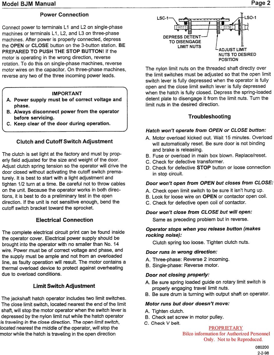
2 Technical Data Sheet Motorized Roof Scuttles & Fire Vents General Notes Smoke Vents 1. Covers oversprung. 2. Cable and drum operation. 3. BJM type motor operation. 4. Single Leaf One motor operator per unit. 5. Double Leaf, Quad, Multi Component and Acoustical One motor operator per pair of covers. Roof Scuttles 1. Covers balanced, not oversprung. 2. One motor operator per leaf. 3. Single Leaf model Motion Systems. Double Leaf model Motion Systems. (Qty 2) 4. Motors are located inside the frame opening. 5. Ball screw actuated. 6. Motorized units are available on sloped roofs. Motorized Roof Scuttles & Fire Vents 6/27/03
 4. Motors are located inside the frame opening.")
3 Technical Data Sheet Motorized Roof Scuttles & Fire Vents Sidewalk Doors 1. Covers balanced, not oversprung. 2. One motor operator per leaf. 3. Single Leaf model Motion Systems. Double Leaf model Motion Systems (Qty 2). 4. Ball screw actuated. General 1. Standard power requirements: 115 VAC, 9.71 Amps, Single Phase, 60 Cycle, ½ hp (BJM motors only) other power requirements available at extra cost upon request. 2. Control box for Motion Systems motor: A. Single leaf Zener. B. Double leaf Zener. 3. (3) Pushbutton control station (open, close, stop) standard options: A. Outdoor Nema type 3R (3) pushbutton control station. B. (3) Pushbutton control station keyed on stop. Note: (3) pushbutton control station built into control box for motion systems motor. 4. Wiring at site by others. 5. Motor operator has separate one-year warranty. Motorized Roof Scuttles & Fire Vents 6/27/03
 Pushbutton control station (open, close, stop) standard options: A. Outdoor Nema type 3R (3) pushbutton control station. B. (3) Pushbutton control station keyed on stop.")
4 TECHNICAL DATA SHEET MOTORIZED SINGLE LEAF FIRE VENT MODEL FIRE VENT- MOTORIZED SINGLE LEAF TYPE BJM MOTOR OPERATOR NOTE: SPRINGS, SHOCK & GUIDE ARM (NO HOLD OPEN ARM) NOT SHOWN FIRE VENT-MOTORIZED SINGLE LEAF 7/2/03
 NOT SHOWN FIRE VENT-MOTORIZED SINGLE LEAF")
5 TECHNICAL DATA SHEET MOTORIZED DOUBLE LEAF FIRE VENT MODEL MOTORIZED DOUBLE LEAF FIRE VENT NOTE: SPRINGS, SHOCK & GUIDE ARM (NO HOLD OPEN ARM) NOT SHOWN FV-MOTORIZED DL 9/4/2001
 NOT SHOWN FV-MOTORIZED DL")
6 TECHNICAL DATA SHEET MOTORIZED DOUBLE LEAF FIRE VENT MODEL FIRE VENT- MOTORIZED DOUBLE LEAF TYPE BJM MOTOR OPERATOR NOTE: SPRINGS, SHOCK & GUIDE ARM (NO HOLD OPEN ARM) NOT SHOWN FIRE VENT-MOTORIZED DOUBLE LEAF 7/2/03
 NOT SHOWN FIRE VENT-MOTORIZED DOUBLE LEAF")
7 TECHNICAL DATA SHEET MOTORIZED ACOUSTICAL LEAF FIRE VENT MODEL FIRE VENT- MOTORIZED- ACOUSTICAL FIRE VENT-MOTORIZED-ACOUSTICAL.doc 1/4/02

8 TECHNICAL DATA SHEET MOTORIZED ACOUSTICAL FIRE VENTS PLAN VIEW MODEL FIRE VENTS- MOTORIZED- PLAN VIEW FIRE VENTS-MOTORIZED-PLAN VIEW 8/13/2001

9 TECHNICAL DATA SHEET MOTORIZED SINGLE LEAF ROOF SCUTTLE MODEL ROOF SCUTTLE- MOTORIZED SINGLE LEAF NOTE: - Motor extends into frame opening 5. - Wiring diagram stored in control box - All wiring done by customer in field RS-SINGLE LEAF-MOTOR 6/16/03

10 TECHNICAL DATA SHEET MOTORIZED DOUBLE LEAF ROOF SCUTTLE MODEL ROOF SCUTTLE- MOTORIZED DOUBLE LEAF NOTE: - Motor extends into frame opening 5. - Wiring diagram stored in control box - All wiring done by customer in field RS-DOUBLE LEAF-MOTOR 6/16/03

11 TECHNICAL DATA SHEET MOTORIZED J OR J-AL SIDEWALK DOOR MODEL SIDEWALK DOOR- MOTORIZED J NOTE: - Motor extends into frame opening 5 - Support behind motor required (by customer) - All wiring done by customer in field SW-J-MOTOR 6/16/03
 - All wiring done by customer in field")
12 TECHNICAL DATA SHEET MOTORIZED JD OR JD-AL SIDEWALK DOOR MODEL SIDEWALK DOOR- MOTORIZED JD NOTE: - Motor extends into frame opening 5. - Support behind motor required(by customer). - All wiring done by customer in field. SW-JD-MOTOR 6/16/03
.")
13 Technical Data Sheet Motorized Fire Vents Operating Instructions Motorized units This is a motorized fire vent that has been test operated at the factory. Prior to electrical hookup, the cover may be opened manually by removing the shipping wire. Use care since the cover is spring-loaded and will open by itself when released. During construction, the cover may be closed manually and tied closed temporarily with wire or rope until the electrician arrives. Do not detach the cable of disturb in any way the relationship between the cable and the cable drum as this affects the limit switch adjustment. The limit switches have been factory set and normally should not need field adjustments. After the electrician provides power to the motor operator, push the CLOSE button. The cable drum must rotate clockwise to close. If the cable drum rotates counterclockwise when the CLOSE button is activated, then push the STOP button immediately and reverse the power. See enclosed wiring diagram. (Osco Rev. Q). With the cable drum rotating in the proper direction, check to be sure the covers close down firmly onto the frame and that the motor operator automatically shuts itself off. If the cover does not close all the way, or if the motor continues to run with the cover closed, push the STOP button and adjust the CLOSE limit switch. In the same manner, check the OPEN limit switch adjustment. In the event of a fire, the fusible link will release the cable from the cover and the cover will open. To reattach the cable to the cover, first be sure the motor operation is in the open position and the cable unwound from the drum. Then attach the cable to the cover using a new fusible link. Push the CLOSE button and recheck the limit switch adjustment described above. An inside manual release pull cable has been provided for emergency use only. After use, check to be sure clutch pins re-engage and recheck limit switch setting. The motor operator is also equipped with a 24 VDC relay for use with a fire control system. When an electrical signal is received by the relay, the motor rotates the drum allowing the cable to unwind to the open position. To close the covers, push the CLOSE button on the 3 Push Button remote included with the vent. MOTOR-INST 4/30/10

14 Technical Data Sheet Instructions for Motorized Roof Scuttles & Sidewalk Door To attach motor to unit: 1. Attach lower end of motor to bracket on the frame using clevis pin, cotter pin, and spacers provided (as shown in Fig. 1 & 1a). NOTE: Wired end of motor must be oriented so that wires are directed toward the junction box (as shown in Fig. 2). Figure 1 Figure 1a Figure 2 MOTOR inst 4 10/8/14
.")
15 Technical Data Sheet Instructions for Motorized Roof Scuttles & Sidewalk Door 2. Attach upper end of motor shaft to bracket on the cover in the same manner as above. Cover may have to be maneuvered in open position in order to properly locate shaft. Shaft may be rotated manually, but not raised or lowered. NOTE: This step may require 2 assemblers. 3. Repeat above steps for second motor (double leaf doors only). 4. Ensure that cotter pins are secure and motor is solidly in place before wiring. To wire unit to control panel: 1. Wire unit according to the diagrams shown for single leaf (Fig. 3) or double leaf (fig. 4). Additional wiring information is included inside the control box. (10-wire cable minimum required for single leaf, 14-wire cable minimum required for double leaf). Figure 3 MOTOR inst 4 10/8/14
 or double leaf (fig. 4). Additional wiring information is included inside the control box.")
16 Technical Data Sheet Instructions for Motorized Roof Scuttles & Sidewalk Door Figure 4 2. Check operation of all components. Adjust limit switches if necessary. a. Push OPEN button to see that cover(s) moves toward the open position. If the cover(s) moves toward the closed position, push the STOP button immediately. To correct, reverse the leads in terminals 5&6 (for single leaf) or in terminals 7&8 and 9&10 (for double leaf). These terminals are on the junction box. b. Limit switches are factory set and should not need to be adjusted. However, if adjustment is necessary, switches are easily adjustable by loosening the setscrew (front/center of switch) and sliding the arm up or down, then tightening the screw when switch is properly adjusted. If unit is opened and the motor does not cease operation at the full open position, press the STOP button and adjust the open limit switch (located at the hinge side) by sliding the arm slightly downward. The switch should pivot when the cover is fully open. If unit is closed and the motor does not cease operation, press the STOP button and adjust the close limit switch upward. Lastly, if the unit is closed but the motor ceases operation before the unit is fully closed, the close switch must be adjusted downward. It is imperative (to prevent damage) that the cover(s) moves in the direction of the button pushed. MOTOR inst 4 10/8/14
 and sliding the arm up or down, then tightening the screw when switch is")
17

18
19

20

21
22
HP Laser Jet 4200/4240/4250/4300/4350 Swing Plate
 HP Laser Jet 4200/4240/4250/4300/4350 Swing Plate 1 Swing Plate Assembly-RM1-0043 1 Swing Plate Kit-5851-2766 (RM1-0043 plus RM1-1091 gear) CAUTION: Fuser may be hot. Turn off printer, unplug it and allow
WE-350 Series ¼ Turn Electric Actuator
 WE-350 Series ¼ Turn Electric Actuator Operation and Installation Manual Pg 1 (Rev. 020113) Table of Contents 1.0 General 1.1 Pre-Installation Inspection 1.2 Storage 1.3 Features & General Information
Owner's Copy. 104873 December 14, 2011 ELECTRICAL INSTRUCTIONS FOR ADVANTEX EA OR EX MODELS
 104873 December 14, 2011 Detex Corporation, 302 Detex Drive, New Braunfels, Texas 78130-3045 (830)629-2900 / 1-800-729-3839 / Fax (830)620-6711 E-MAIL: detex@detex.com INTERNET: www.detex.com ELECTRICAL
SECTION G2: CABLE PROCESSOR MODULE MAINTENANCE
 SECTION G2: CABLE PROCESSOR MODULE MAINTENANCE Cable Processor Module overview WARNING! When tipping the Cable Processor Module back, (after removing the toggle arm pin), use extreme caution not to drop
GEH6290. Mechanism Circuit Breaker. Handle Operating Mechanism Cat. No. Type NEMA 1, 3R, 12, 13 NEMA 4/4X Cat. No. Cat. No. Series Instruction
 GEH6290 g Cable Operator Mechanisms for E150, SE150, SF250, and SG600 Spectra RMS Circuit Breakers Type SCH1/1X, SCH2/2X Flange-Mounted Handle Assemblies, Cable Series SC3L SC10L and Type SC0M1A, SCOM1EF,
SHIFT INTERLOCK SYSTEM SHIFT INTERLOCK SYSTEM
 SHIFT INTERLOCK SYSTEM The shift lock system is designed to ensure the proper operation of the automatic transmission. The driver must depress the brake pedal in order to move the gear selector from Park
1. SAFETY RULES WARNING TO REDUCE THE RISK OF FIRE, ELECTRIC SHOCK OR PERSONAL INJURY, MOUNT FAN TO OUTLET BOX MARKED "ACCEPTABLE FOR FAN SUPPORT".
 1 1. SAFETY RULES 1. To reduce the risk of electric shock, insure electricity has been turned off at the circuit breaker or fuse box before beginning. 2. All wiring must be in accordance with the National
Short Range Wireless Switch System Handheld 8 Installation and Operations Guide
 Phone: (866) 701-1146 Fax: (425) 216-7558 www.remotecontroltech.com Short Range Wireless Switch System Handheld 8 Installation and Operations Guide Introduction... 2 Before Installation... 2 Receiver Installation...
LUCCI AIRFUSION QUEST II CEILING FAN
 LUCCI AIRFUSION QUEST II CEILING FAN WITH IR REMOTE INSTALLATION OPERATION MAINTENANCE WARRANTY INFORMATION CAUTION READ INSTRUCTIONS CAREFULLY FOR SAFE INSTALLATION AND FAN OPERATION. V1.0 QUEST II IR
ETZGAR CONVEYOR COMPANY Controls Section v12.05
 Section 7 Controls Page Description 7-1 Controls Index 7-2 Motor Data, Enclosure Rating and Abbreviations 7-3 Controls Safety Guidelines 7-4 Fixed Speed Controls Packages 7-5 Three Phase AC Variable Speed
60" TulleTM. Instruction Manual. A Kichler Select ceiling fan
 60" TulleTM A Kichler Select ceiling fan Kichler Lighting 7711 East Pleasant Valley Road P.O. Box 318010 Cleveland, Ohio 44131-8010 Customer Service 866.558.5706 8:30 AM to 5:00 PM EST, Monday - Friday
INSTALLATION INSTRUCTIONS
 INSTALLATION INSTRUCTIONS VOLT LED Edge-Lit Flat Panel VFP-22 and VFP-24 Series Help Hotline: 1-813-978-3700 Mon-Fri 8am-8pm Sat-Sun 10am - 6pm (EST) Specifications and product details subject to change
Installation Instructions
 Installation Instructions S50-310 (Semi-Circular) S50-311 (Circular) Accu-Zone Infrared Control Conversion Kit for Terrazzo & Stainless Steel Classic Washfountains (Non-sectional) Table of Contents Pre-Installation
Original Assembly Guide
 TCT Multipurpose Single Bevel Sliding Compound Mitre Saw Original Assembly Guide Read instructions before assembling this tool. Table of Contents GB Assembly Guide Read instructions before assembling this
Roll-Up Door Maintenance Guide
 R Roll-Up Door Maintenance Guide Cable Replacement on Two Spring Type Balancer Page 1 Panel Replacement - Removable Roller Cover Type Bottom Panel Page 1 Panel Replacement - Removable Roller Cover Type
1. SAFETY RULES. 8. Avoid placing objects in the path of the blades.
 1 1. SAFETY RULES 1. To reduce the risk of electric shock, insure electricity has been turned off at the circuit breaker or fuse box before beginning. 2. All wiring must be in accordance with the National
INSTALLATION MANUAL MODEL RP-100
 INSTALLATION MANUAL FOR 24 VALVE 5.9L CUMMINS POWERED DODGE TRUCKS 2003 THROUGH 2004.5 MODEL RP-100 READ THESE INSTRUCTIONS THOROUGHLY BEFORE BEGINNING INSTALLATION 5400 BUSINESS 50 WEST SUITE 8 573 635-0555
Series 30000 Hose Reels
 Operating Instructions and Parts List for Series 30000 Hose Reels - MANUAL DRIVEN - - POWER DRIVEN - SAFETY PRECAUTIONS Personal injury and/or equipment damage may result if proper safety precautions are
Model 2300DR Installation Guide
 Model 2300DR Installation Guide POWER ACCESS CORPORATION P.O. BOX 1050 170 MAIN STREET NEW HARTFORD, CT 06057 800-344-0088 WEBSITE: www.power-access.com EMAIL: salesinfo@power-access.com 1 STANDARD PARTS
Operating Instructions
 587W Clinical Care Recliner Operating Instructions 587W-INS-LAB Graham-Field Health Products 2005 IMPORTANT: READ THIS MANUAL BEFORE OPERATING YOUR ORTHO-BIOTIC CLINICAL CARE RECLINER WARNINGS Warning:
TS93 EMR T/PT/TDE. Surface applied door closer
 TS EMR T/PT/TDE Surface applied door closer Installation instructions: Pull side track mount door closer with smoke detector (EMR T) Push side track mount door closer with smoke detector (EMR PT) Double
Ceiling Fan Installation Instructions
 Ceiling Fan Installation Instructions 1525..series OWNER S MANUAL READ AND SAVE THESE INSTRUCTIONS Total fan wieght with light kit 1-1525-CUL-English INSTALLATION CH-545 Safety Tips WARNING: TO REDUCE
JANUS INTERNATIONAL CORPORATION INSTALLATION INSTRUCTIONS Pantheon Mini Operator
 JANUS INTERNATIONAL CORPORATION INSTALLATION INSTRUCTIONS Pantheon Mini Operator The Janus Pantheon mini operator does not typically require the provision of any additional site requirements other than
DETACHABLE WINDSHIELD AND DOCKING HARDWARE KIT
 -J00 REV. 00-- DETACHABLE WINDSHIELD AND DOCKING HARDWARE KIT GENERAL Kit Number -A, 0-, -, 0-, -, - 0, -0 Models These kits fit and later FXST, FXSTB, FXSTC, and and later FXDWG Harley-Davidson model
Small Flat Panel Lift Arm FSA-1004 and KSA-1004
 I N S T A L L A T I O N I N S T R U C T I O N S Small Flat Panel Lift Arm FSA-1004 and KSA-1004 The Lift Arm is an accessory that can be used with a broad range of Small Flat Panel Displays. The allows
149mm. Walk-Thru Assembly Gate. MODEL NO: 1161, 1167 Owner s Manual. www.regalo-baby.com
 149mm 210mm Walk-Thru Assembly Gate MODEL NO: 1161, 1167 Owner s Manual READ ALL INSTRUCTIONS BEFORE ASSEMBLY AND USE OF GATE. KEEP INSTRUCTIONS FOR FUTURE USE. www.regalo-baby.com... Regalo International,
Telefon (+45) 43 43 82 00 Telefax (+45) 43 43 74 75 mail@uni-valve.com www.uni-valve.com. Installation and operating manual
 43 43 82 00 Telefax (+45) 43 43 74 75 mail@uni-valve.com www.uni-valve.com. Installation and operating manual") Uni-Valve A /S VENTILER & INSTRUMENTER Telefon (+45) 43 43 82 00 Telefax (+45) 43 43 74 75 mail@uni-valve.com www.uni-valve.com UNI-EL Electric actuator Installation and operating manual Remote position
Uni-Valve A /S VENTILER & INSTRUMENTER Telefon (+45) 43 43 82 00 Telefax (+45) 43 43 74 75 mail@uni-valve.com www.uni-valve.com UNI-EL Electric actuator Installation and operating manual Remote position
CETAC Z-Drive Assembly
 CETAC Z-Drive Assembly Replacement Guide Manual Part Number 610144 Rev 1, 2012 CETAC Technologies, Printed in USA Overview This guide describes the necessary steps to replace the Z-drive assembly on your
E, EA & EL Series Balancer Service Manual
 AERO-MOTIVE COMPANY A Woodhead Industries, Inc. Subsidiary E, EA & EL Series Balancer Service Manual IMPORTANT SAFETY INSTRUCTIONS Please read this manual carefully and follow its instructions. Improper
Owners & Installation Manual for the Sheridan, Mountainair, Pine Valley and Old Forge Ceiling Fan Family
 Owners & Installation Manual for the Sheridan, Mountainair, Pine Valley and Old Forge Ceiling Fan Family Part of the Kiva Lighting Family Custom Lighting and Fans Since 1992 1312 12th St NW Albuquerque,
Atlanta CAUTION READ INSTRUCTIONS CAREFULLY FOR SAFE INSTALLATION AND FAN OPERATION. IF UNSURE CONSULT A QUALIFIED ELECTRICIAN
 OWNERS INSTRUCTION MANUAL 30 /76cm Atlanta INSTALLATION OPERATION MAINTENANCE CAUTION READ INSTRUCTIONS CAREFULLY FOR SAFE INSTALLATION AND FAN OPERATION. IF UNSURE CONSULT A QUALIFIED ELECTRICIAN PAGE
AVENTOS HF Wood / wide aluminum door application
 AVENTOS HF Wood / wide aluminum door application Lift mechanism set Lift mechanism (qty 2) #7 x 35 mm (-3/8 ) wood screw (qty 0) Power factor 85 230 ( lift mechanism req.) 20F2200.N5 23 470 20F2200.N5
INSTALLATION MANUAL MODEL RP-150
 INSTALLATION MANUAL FOR 24 VALVE 5.9L CUMMINS POWERED DODGE TRUCKS 2003 THROUGH 2004.5 MODEL RP-150 READ THESE INSTRUCTIONS THOROUGHLY BEFORE BEGINNING INSTALLATION 5400 BUSINESS 50 WEST SUITE 8 573 635-0555
INSTALLATION INSTRUCTIONS
 LIGHTING CONTROL PANELS 4 AND 8 RELAYS INSTALLATION INSTRUCTIONS INSTALLATION OVERVIEW The installation instructions contained in this document are provided as a guide for proper and reliable installation.
GPS AutoSteer System Installation Manual
 GPS AutoSteer System Installation Manual Supported Vehicles John Deere Sprayers 4720 4630 4730 4830 AutoTrac Ready PN: 602-0227-01-A LEGAL DISCLAIMER Note: Read and follow ALL instructions in this manual
PRODUCT: WASHER / WASHER-DRYER COMBO MODEL: AW 120 / AW 122 / AW 125 AWD 120 / AWD 121 / AWD 129
 PRODUCT: WASHER / WASHER-DRYER COMBO MODEL: The information included in this Splendide Repair Manual may change without notice. Please see our web site www.splendide.com/service/docs.html for updates,
KEYPAD LOCK RETROFIT KIT
 KEYPAD LOCK RETROFIT KIT INSTRUCTIONS FOR ASSEMBLY IMPORTANT READ & SAVE THESE INSTRUCTIONS Tools Required for Assembly 5/32 hex (Allen) wrench #2 Phillips screwdriver Isopropyl alcohol or alcohol wipes
2&3 SECTION LOFT LADDER
 TWIST CATCH ASSEMBLY A4 A2 A1 A3 A7 A6 A5 2&3 SECTION LOFT LADDER Images feature the 3 section loft ladder, but the same instructions apply to both 2 & 3 section ladders Installation and Operating Instructions
3 IN 1 BATHROOM HEATER
 3 IN 1 BATHROOM HEATER MODEL NO.: A515 - SH MINI FUNCTION: HEATER, EXHAUST FAN AND LIGHT Dear customers, Thank you for selecting the AUPU 3 in 1 Bathroom Heater. Please read all instructions before commencing
ADDING AN ELECTRIC AUXILIARY FAN TO RADIATOR STACK ON 03 ALPINE COACH
 ADDING AN ELECTRIC AUXILIARY FAN TO RADIATOR STACK ON 03 ALPINE COACH The original design of the 03 Alpine Coaches (and perhaps other years as well) did not include any kind of engine fan engage mechanism
How To Use A 4200 Electric Compact Convection Oven
 OWNER S MANUAL ELECTRIC COMPACT CONVECTION OVEN MODELS: 4200 4292 FORM NO.: S-2374 REV: A 02/07 An Employee Owned Company PRINTED IN U. S. A. 35 Garvey Street Everett MA 02149 Tel: (617) 387-47100 Fax:
450 SERIES SLIDING GLASS DOOR ASSEMBLY AND INSTALLATION INSTRUCTIONS
 450 SERIES SLIDING GLASS DOOR ASSEMBLY AND INSTALLATION INSTRUCTIONS Effective 2/12/11 Revised 7/7/15 TACOMA, WA (253) 922-6030 PORTLAND, OR (503) 682-3270 MARYSVILLE, WA (360) 659-0836 SACRAMENTO, CA
6 inch A-Arm Lift Kit WARNING: 16-018/16-019. installation instructions. will fit CLUB CAR DS. included:
 Revised May 205 6-08/6-09 6 inch A-Arm Lift Kit will fit CLUB CAR DS installation instructions included: Rear Lift Blocks Main Suspension Assembly Spindles A-Arms Rear Shock Mounting Plates U-Bolts WARNING:
Multi-Pitch Pitching Machine USER MANUAL
 Multi-Pitch Pitching Machine USER MANUAL TABLE OF CONTENTS Thank you for purchasing the Cimarron Multi-Pitch Pitching Machine. The Cimarron Multi-Pitch Pitching Machine is a high performance pitching machine
IMPACT SPRINKLER TROUBLESHOOTING GUIDE
 RAIN USE AND OPERATION BIRD IMPACT SPRINKLER TROUBLESHOOTING GUIDE The diagrams below depict typical Rain Bird sprinklers with all available controls. Your particular model may have only some of these
Speed-Mat Rectangle Cutter
 Speed-Mat Rectangle Cutter 1 Honeycomb baseboard. 2 Left hold down. 14 3 Bottom hold down. 4 4 Left / right rule. 8 5 8 5 Left / right rule pointer. 1 6 Top / bottom rule. 7 Top / bottom rule pointer.
Bulletin 840 Float Switch and Operator Assembly Instructions
 Bulletin 840 Switch and nstructions ATTETO: Disconnect all power before wiring float switch and motor. Secure cover before reconnecting power. Test float switch operator assembly manually before leaving
GE Wireless Devices Battery Replacement
 60-506-319.5 Crystal Smoke Detector Two 9V Duracell 9V 1. Twist counter-clockwise until detector become loose from base. 2. Replace batteries observing correct polarity. 3. Replace detector by twisting
BODY-12, Door Handle - Removal, Installation, and Adjustment
 Introduction BODY-12, Door Handle - Removal, Installation, and Adjustment There are many different procedures floating around describing how to replace the door handles on a 944 and every one of them will
WINDOW REPAIR MANUAL & REFERENCE GUIDE
 WINDOW REPAIR MANUAL & REFERENCE GUIDE TABLE OF CONTENTS DOUBLE HUNG & SINGLE HUNG PARTS 4-5 CASEMENT PARTS 6 SCREEN PARTS 7-8 HOW TO REMOVE TILT-IN SASH 9 HOW TO REMOVE A BALANCE 10 HOW TO INSTALL BALANCE
Installation Instructions
 Installation Instructions For Use with PXPV230, PXPV265, PXPD230, and PXPD265 models Attention! - Please read these instructions completely before attempting installation. Always unplug the power supply
V1504 Vertical Platform Lift OWNER S MANUAL
 V1504 Vertical Platform Lift OWNER S MANUAL (To Be Retained by Owner After Installation by Authorized Savaria Dealer) Part No. 000692 01-m03-2016 2 IMPORTANT Ensure that only an authorized Savaria Dealer
I nstallation. M100Q Series Proportional Actuator with R81Q Controller Board for Thermistor Sensor Applications. Tools Needed.
 FANs 268.1, 1628.3 Installation Bulletin M100Q Issue Date 1099 M100Q Series Proportional Actuator with R81Q Controller Board for Thermistor Sensor Applications I nstallation Parts Included M110QGA-1 and
1/29/2008 DR50. Baja Motorsports Inc. P.O. Box 61150 Phoenix, AZ 85082 Toll Free: 888-863-2252 PART NUMBERS PRICES ARE SUBJECT TO CHANGE 1 of 45
 DR50 Toll Free: 888-863-2252 PART NUMBERS PRICES ARE SUBJECT TO CHANGE 1 of 45 CYLINDER & CYLINDER HEAD Part UPC Number Description Baja Description 1 DR50-001 842645074424 CYLINDER 1 1 2 DR50-002 842645074431
N20xxA, N34xxA NON-SPRING RETURN DIRECT-COUPLED DAMPER ACTUATORS FOR FLOATING AND 2-POSITION CONTROL
 N2xxA, N34xxA NON-SPRING RETURN DIRECT-COUPLED DAMPER ACTUATORS FOR FLOATING AND 2-POSITION CONTROL SPECIFICATIONS Supply voltage N224A / N3424A N223A / N3423A PRODUCT DATA 24 Vac 15%, 5/6 Hz 23 Vac 15%,
AUTO TRANS DIAGNOSIS Article Text 1998 Volkswagen Passat This file passed thru Volkswagen Technical Site - http://volkswagen.msk.
 AUTO TRANS DIAGNOSIS Article Text 1998 Volkswagen Passat This file passed thru Volkswagen Technical Site - http://volkswagen.msk.ru ARTICLE BEGINNING 1997-98 AUTOMATIC TRANSMISSIONS Volkswagen Shift Interlock
Range Road RR Series Semi-Automatic Firewood Processor. Crated Unit Assembly Manual
 Range Road RR Series Semi-Automatic Firewood Processor Crated Unit Assembly Manual 1 1) Undo 8-18mm x 19mm Nuts and bolts, 2 on each leg of top frame 2) Lift top of Metal crate off and move out of work
HOME GYM. Model. Retain This Manual for Reference OWNER'S MANUAL. www.hyper-extension.com
 NOTE: Please read all instructions carefully before using this product Table of Contents Safety Notice www.hyper-extension.com HOME GYM 50036 Hardware Identifier Assembly Instruction Parts List Warranty
Welding Reel ERA 4000 Service Manual
 AERO-MOTIVE COMPANY A Woodhead Industries, Inc. Subsidiary Welding Reel ERA 4000 Service Manual IMPORTANT SAFETY INSTRUCTIONS Please read this manual carefully and follow its instructions. Improper use
Table of Contents. www.hunterfan.com. What to Expect with. Preparation. Tools Needed. Wiring. Hanging the Fan. Blades. Motor Housing.
 www.hunterfan.com Table of Contents What to Expect with Your Installation 30 inches Hanging the Fan Wiring 8 Maintenance, Operation & Cleaning Light Kit 13??? 14 1 9 Troubleshooting 11 5 Blades Motor Housing
POWER LOCK KIT GENERAL INSTALLATION -J04427 REV. 2007-12-04. Kit Number. Models. Additional Parts Required. Kit Contents
 -J0 REV. 00--0 POWER LOCK KIT GENERAL Kit Number -0, 0-0 Models For model fitment information, please see the P&A Retail Catalog or the Parts and Accessories section of www.harleydavidson.com (English
MBSAW. Meat Cutting Band Saw With Meat Grinder Assembly & Operating Instructions
 06/2011 MBSAW Meat Cutting Band Saw With Meat Grinder Assembly & Operating Instructions READ ALL INSTRUCTIONS AND WARNINGS BEFORE USING THIS PRODUCT. This manual provides important information on proper
BOBBIN WINDER - TYPES & FUNCTION
 BOBBIN WINDER - TYPES & FUNCTION 13.1.006 The bobbin winder is a separate unit screwed on to the machine, adjacent to the balance wheel. Its function is to wind a reserve of cotton evenly onto an empty
Rating when used as a weight carrying hitch without spring bars:
 BOLT-TOGETHER WEIGHT DISTRIBUTING HITCH SYSTEM Rating when used as a weight distributing hitch with spring bars: Part Number 48051 4805 48053 48054 Max Tongue Weight 550 Ibs. 750 Ibs. 1000 Ibs. 1400 lbs.
Andersen Electric Window Opener for Andersen Awning and Roof Windows
 W A Electric Window Opener Electric Window Opener for Awning and Roof Windows Congratulations! You have just purchased one of the many fine products. For ease of installation and continued enjoyment of
CortezTM A Kichler Décor Ceiling Fan
 CortezTM A Kichler Décor Ceiling Fan Kichler Lighting 7711 East Pleasant Valley Road P.O. Box 318010 Cleveland, Ohio 44131-8010 Customer Service 866.558.5706 8:30 AM to 5:00 PM EST, Monday - Friday Instruction
Left Hand Limit Switch. Housing. Left Hand. Connections. Motor Connector BROWN PURPLE GRAY BLACK DARK BLUE BLACK BROWN BROWN LIGHT BLUE.
 LIGHT BLUE GRAY PURPLE Circuit Breaker Intput Circuit Breaker Output #1 Relay Left Hand Limit Switch Housing Left Hand Motor Connector Right Hand Limit Switch on Radiator Support Right Hand Limit Switch
WILDING WALLBEDS BUNK BED INSTALLATION INSTRUCTIONS
 WILDING WALLBEDS BUNK BED INSTALLATION INSTRUCTIONS Instruction Booklet 18 WARNING! ALL MURPHY/WALLBED SYSTEMS CONTAIN POWERFUL LIFTING COMPONENTS. FAILURE TO USE AND FOLLOW THESE INSTRUCTIONS DURING THE
Heat Surge Model X5C Fire Place Insert Service Manual Applies to all units w/30000208 circuit board
 Heat Surge Model X5C Fire Place Insert Service Manual Applies to all units w/30000208 circuit board 2012 HS M4417A BR16597R-1 HEAT SURGE 8000 FREEDOM AVE, N. CANTON, OH 44720 330-244-8161 WWW.HEATSURGE.COM
Rollator Cane and Brake Replacement SAFETY SUMMARY (CONTINUED)
") Rollator Cane and Replacement Assembly, Installation and Operating Instructions SAVE THESE INSTRUCTIONS NOTE: Check ALL parts for shipping damage. If shipping damage is noted, DO NOT use. Contact Carrier/Dealer
Rollator Cane and Replacement Assembly, Installation and Operating Instructions SAVE THESE INSTRUCTIONS NOTE: Check ALL parts for shipping damage. If shipping damage is noted, DO NOT use. Contact Carrier/Dealer
Control Box Wiring For PRSstandard Tool
 888-680-4466 ShopBotTools.com Control Box Wiring For PRSstandard Tool Copyright 2016 ShopBot Tools, Inc. page 1 Copyright 2016 ShopBot Tools, Inc. page 2 Table of Contents Introduction:...5 Installation:...5
Electric Panel Pump Control System. Operation, Maintenance and Installation Manual
 Manual No. 5EP-OM1-1 Electric Panel Pump Control System Operation, Maintenance and Installation Manual INTRODUCTION... 1 RECEIVING AND STORAGE... 1 DESCRIPTION OF OPERATION... 1 INSTALLATION... 2 SEQUENCE
Front brakes (FN- 3), servicing
, servicing") j a t Front brakes (FN- 3), servicing 46-1 Front brakes, servicing Note: Install complete repair kit. After replacing brake pads and before moving vehicle, depress brake pedal several times firmly to properly
j a t Front brakes (FN- 3), servicing 46-1 Front brakes, servicing Note: Install complete repair kit. After replacing brake pads and before moving vehicle, depress brake pedal several times firmly to properly
P150SC15. Designed for 2015 Ford F150 Super-Cab and Super-Crew vehicles without Sony System. 2015 Stillwater Designs P150SC15-A2-20150813
 P150SC15 Designed for 2015 Ford F150 Super-Cab and Super-Crew vehicles without Sony System Subwoofer Assembly Amplifier Assembly Amplifier Harness 2015 Stillwater Designs P150SC15-A2-20150813 M6 Bolt M6
Assembly and Usage Instructions
 Assembly and Usage Instructions A Product 5885 West Van Horn Tavern Road Columbia, MO 65203 www.caldwellshooting.com Instruction #1001667 Limited Warranty Every Caldwell product is warrantied to be free
GUTTER MACHINE CONTROLS STANDARD
 GUTTER MACHINE CONTROLS STANDARD Note: determine what type of control package is installed on the machine. --more-- All operators should familiarize themselves with the appropriate controls prior to any
Mounting Tripod Kit Installation Manual
 Mounting Tripod Kit Installation Manual For use with Davis s wireless and cabled Vantage Pro2 weather stations, the Mounting Tripod simplifies installation. The tripod supports the Integrated Sensor Suite
TERMINATION EQUIPMENT INSTRUCTION MANUAL TELE-PIERCE P/N 356-246
 TERMINATION EQUIPMENT INSTRUCTION MANUAL TELE-PIERCE P/N 356-246 OPERATION AND SERVICE INSTRUCTIONS AMPHENOL 157 SERIES TELE-PIERCE MULTI-WIRE TERMINATION TOOL 356-246 AMPHENOL TERMINATION SYSTEMS 1830
Gripper Kit for the Boe-Bot Robot (#28202)
") 599 Menlo Drive, Suite 100 Rocklin, California 95765, USA Office: (916) 624-8333 Fax: (916) 624-8003 General: info@parallax.com Technical: support@parallax.com Web Site: www.parallax.com Educational: www.stampsinclass.com
599 Menlo Drive, Suite 100 Rocklin, California 95765, USA Office: (916) 624-8333 Fax: (916) 624-8003 General: info@parallax.com Technical: support@parallax.com Web Site: www.parallax.com Educational: www.stampsinclass.com
Model 854/856. Operating and Assembly Manual. Palmor Products Inc. 5225 Serum Plant Road Thorntown, IN 46071
 Model 854/856 Operating and Assembly Manual Palmor Products Inc. 55 Serum Plant Road Thorntown, IN 46071 3/31/2015 SAFETY RULES Remember, any power equipment can cause injury if operated improperly or
INSTALLATION INSTRUCTIONS
 INSTALLATION INSTRUCTIONS Electric Vacuum Pump Kit 28146 Thank you for choosing STAINLESS STEEL BRAKES CORPORATION for your braking needs. Pleases take the time to read and carefully follow these instructions
MARK-3 DIS Digital Ignition Solution
 Overview: MARK-3 DIS Digital Ignition Solution WATERAX offers a conversion kit Digital Ignition Solution (DIS) for users that want to convert a MARK-3 from breaker points and mechanical cut-out switch
Ceiling Mounted Folding Attic Ladders Installation Instructions
 Ceiling Mounted Folding Attic Ladders Installation Instructions WARNING Before you start installing your new Louisville Ceiling Mounted Folding Attic Ladder, you must read and understand the following:
HOLLISTER-WHITNEY ROPE GRIPPER
 HOLLISTER-WHITNEY ROPE GRIPPER Instructions for Model #620GA1, 620GA2 (Patented worldwide, other patents pending) WARNING: KEEP HANDS CLEAR OF ROPE GRIPPER. FORCES CREATED CAN CRUSH FINGERS. Figure 1 ROPE
1000-LB. TRAILER JACK OWNER S MANUAL
 1000-LB. TRAILER JACK OWNER S MANUAL WARNING: Read carefully and understand all INSTRUCTIONS before operating. Failure to follow the safety rules and other basic safety precautions may result in serious
BUILT-IN DISHWASHER INSTALLATION INSTRUCTIONS
 BUILT-IN DISHWASHER INSTALLATION INSTRUCTIONS PLEASE READ COMPLETE INSTRUCTIONS BEFORE YOU BEGIN LEAVE INSTALLATION INSTRUCTIONS AND USER'S GUIDE WITH OWNER ALL ELECTRIC WIRING AND PLUMBING MUST BE DONE
BICO CHIPMUNK JAW CRUSHER - TYPE WD
 BICO CHIPMUNK JAW CRUSHER - TYPE WD The Bico Chipmunk Jaw Crusher is designed to give long and efficient service. In order to secure the long life and excellent performance that your crusher is capable
Utility Distribution Systems
 Utility Distribution Systems 6/2012 A0011037 1 WARRANTY This equipment is warranted to be free from defects in materials and workmanship, under normal use and service, for a period of 12 months from date
Operation and Maintenance manual. fusible shunt trip switch
 Operation and Maintenance manual fusible shunt trip switch Table of Contents Fusible Shunt Trip Switch Device Overview... 2 Installation Instructions... 3 Catalog Number Selection Table... 4 Motor Fuse
GLOLAB Two Wire Stepper Motor Positioner
 Introduction A simple and inexpensive way to remotely rotate a display or object is with a positioner that uses a stepper motor to rotate it. The motor is driven by a circuit mounted near the motor and
Manual for GlobePharma Mini-Press II Rotary Tablet Press
 1 of 13 Preparing the Rotary Press 1. Make sure the rotary press is unplugged. 2. Open the bottom cabinet of the rotary press and take out the grey tool kit, and the beige box of punches and dies. 3. Take
specializing in AIR CONDITIONING, PARTS AND SYSTEMS for your classic vehicle PERFECT FIT IN-DASH HEAT/ COOL/ DEFROST 1967-72 CHEVROLET PICKUP
 specializing in AIR CONDITIONING, PARTS AND SYSTEMS for your classic vehicle PERFECT FIT IN-DASH HEAT/ COOL/ DEFROST 1967-72 CHEVROLET PICKUP CONTROL & OPERATING INSTRUCTIONS The controls on your new Perfect
DR50 Hensim Dirt Runner 49cc Dirt Bike (VIN PREFIX LLCH or LUAH)
") Page 1 of 21 Product Information Baja Web > Product Information > Parts Lists > DIRTBIKE > DR50 Hensim Dirt Runner 49cc Dirt Bike (VIN PREFIX LLCH or LUAH) DR50 Hensim Dirt Runner 49cc Dirt Bike (VIN PREFIX
Page 1 of 21 Product Information Baja Web > Product Information > Parts Lists > DIRTBIKE > DR50 Hensim Dirt Runner 49cc Dirt Bike (VIN PREFIX LLCH or LUAH) DR50 Hensim Dirt Runner 49cc Dirt Bike (VIN PREFIX
MODEL E-AF. Drain Cleaning Machine. Operator s Manual
 MODEL E-AF Drain Cleaning Machine Operator s Manual!!!! FOR YOUR SAFETY Before you operate or maintenance this equipment, READ this manual carefully and completely! Purchase Date: Serial Number: ELECTRIC
Auto-belay Cable Replacement Process
 Auto-belay Cable Replacement Process Version 2.00 WARNING: The air pressure in the auto-belay system is what causes the cable to be retracted when releasing the cable or climbing the wall with the cable
INSTALL/REMOVAL INSTRUCTIONS: WINDOW LIFT MOTOR
 REMOVAL/INSTALL OF WINDOW LIFT MOTOR (742-273) Ford Expedition 1997 2002, Lincoln Navigator 1998 2002, Ford F-150 Super Crew Cab 2001 General Tech Tips: Use painter s tape rather than duct tape to secure
INSTRUCTIONS FOR THE INSTALLATION AND OPERATION OF ACTIVATOR II
 INSTRUCTIONS FOR THE INSTALLATION AND OPERATION OF ACTIVATOR II ELECTRONIC TRAILER BRAKE CONTROL 5500 FOR 2, 4, 6 & 8 BRAKE SYSTEMS IMPORTANT: READ AND FOLLOW THESE INSTRUCTIONS CAREFULLY. KEEP THESE INSTRUCTIONS
Fleck 4650. Service Manual INSTALLATION AND START-UP PROCEDURE TABLE OF CONTENTS JOB SPECIFICATION SHEET
 Fleck 4650 Service Manual TABLE OF CONTENTS JOB SPECIFICATION SHEET...1 INSTALLATION AND START-UP PROCEDURE...1 CONTROL VALVE DRIVE ASSEMBLY...2 CONTROL DRIVE ASSEMBLY FOR CLOCK...3 BYPASS VALVE ASSEMBLY...4
SECTION VII PARTS BREAKDOWN
 SECTION VII PARTS BREAKDOWN 21 REAR TINE TILLER MAIN ASSEMBLY ITEM # PART # QTY DESCRIPTION 1 SEE PAGE 25 1 ENGINE-RIGHT ANGLE DRIVE-PULLEY ASSEMBLY 2 SEE PAGE 27 1 FRAME-TRANSMISSION-HOUSING ASSEMBLY
COMMERCIAL GAS DRYER
 COMMERCIAL GAS DRYER MODELS CGD8990XW0 4 12 Litho In U.S.A. (CMS) (psw) c 2012 WHIRLPOOL CORPORATION Part No. Rev. B TOP AND CONSOLE PARTS 2 TOP AND CONSOLE PARTS 1 Literature Parts W10184516 Installation