air seeder monitor 1020 Air Seeder Monitor Installation & Operation Instructions
|
|
|
- Ilene Day
- 7 years ago
- Views:
Transcription
1 air seeder monitor 1020 Air Seeder Monitor Installation & Operation Instructions

2 1020 Contents 1 Contents 1.0 Introduction General Outline Installation Monitor Installation Power Connection Secondary Head Sensor Installation Sensor Cable Connection Sensor Cable Connection 1020T/1020TF Twin Shoot Models Initial System Checks Operation Power Sensitivity Control Alarm Parts List Troubleshooting Optional Bin Sensor Installation 19

3 1020 Introduction Introduction 1.1 General Outline FarmscanAG manufactures a 1020 Series Airseeder Monitor for both Single Shoot and Twin Shoot installations. The Twin Shoot models (1020T) provided the ability to monitor two independent delivery systems simultaneously. For example, seed and fertiliser may be delivered to separate distributor heads and independently monitored for blockages. The FarmscanAG 1020/1020T Airseeder Monitors detect secondary head blockages by means of sensors (listening devices) bolted onto each secondary distributor head. Material flowing through each distributor head strikes the sensor mounting bolt which conducts the sound into the sensor. The operator is able to adjust the control unit sensitivity so that a bright red light on each sensor is held in the OFF condition for a given rate of seed and fertiliser. When a blockage occurs a red light will illuminate on the relevant sensor and simultaneously activate the cab alarm and warning light. The operator will flick the HOLD switch, thereby freezing the red light on at the blockage point before stopping the machinery. A simple inspection of all the sensors will indicate which head is blocked. Up to 21 Secondary Head sensors may be installed on the same party line wiring system together with optional low bin sensors that connect into the same common wiring loom.
 bolted onto each secondary distributor head.")
4 1020 Introduction 3 Typical Installation Plan Single Shoot Model

5 1020 Introduction 4 Typical Installation Plan Twin Shoot Model

6 1020 Installation Installation 2.1 Monitor Installation Install control unit in tractor cab using bracket and securing knobs supplied. Alternatively, use bracket extensions to secure control unit above or below other Farmscan Monitors. Refer to component illustrations pages Power Connection Control unit must be connected DIRECTLY to the 12 Volt DC battery terminals, using the 8m supplied power cable. The unit has an internal poly fuse for protection, which if tripped will reset after a short period with the unit turned off. Twin shoot model (1020T) is supplied with a power Y connector to supply power to each airseeder monitor. IMPORTANT: Make sure battery connections are clean and tight. Secure the power cable away from hot or moving parts with the supplied cable ties. Disconnect battery terminals when arc welding on machinery.

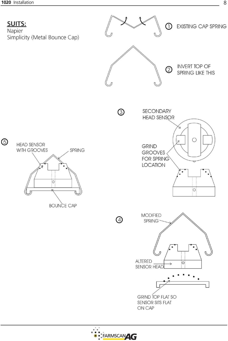
7 1020 Installation Secondary Head Sensor Installation Sensors can be fitted in any way that provides a mechanical link between the sound of flowing material and the inner copper tube of each sensor. The sensor must be isolated from the machinery framework to avoid false activation of the sensor through vibration. Ideally, the bolt will be isolated via the rubber wear pad inside the secondary head inspection cap. HELPFUL TIPS 1. Face all sensor lights towards a single point to make checking easier. 2. Grease inside sensor tube will stop fertiliser buildup and make removal of the bolt easier. 3. When not in use, drop a bag or old container over sensor head to stop parrots chewing the cable close to the sensor. Find the installation option in the following pages that best suits your airseeder model. Mount sensors upside down with copper spacer fitted as shown below to avoid distortion of rubber bounce cap for airseeder models shown below. Example: John Deere John Shearer Big Rig Horwood Bagshaw Simplicity Existing nut must remain in place. Insert washers as shown below. SUITS: Flexicoil

8 1020 Installation 7 The sensor can be attached to the rubber feed hose as shown below - close to the distributor head. Example: Early Ryan models Alfarm (CSN) New Holland Morris Example: International Gason Ford Symonds If mounting sensors with legs downwards, then copper spacer must be installed as shown below to prevent damage to sensor caused by over tightening wingnut. Example: Connershea Fusion Mount the sensor centrally between drop tubes as shown below. NOTE: With Connershea, airseeder springs may need to be modified to secure cap.

9 1020 Installation 8
10 1020 Installation Sensor Cable Connection Use the 5m tractor cable to connect from the monitor to the rear of the tractor. Ensure breakaway socket is secured away from risk of contamination by hydraulic oil. Use the separate 40 metre roll of 3 core sensor cable and 3 pin breakaway connectors to make up suitable extension cables to reach 4 way junction box mounted at centre of cultivator bar. Interconnect all sensors using weather proof junction boxes. Secure junction boxes and cables away from risk of damage using cable ties supplied. Simply cut and join as required making sure to always match the same cable colours together in the Junction Box. Tighten weatherproof glands and seal junction boxes with silastic or grease around the lid before replacing screws.

11 1020 Installation Sensor Cable Connection 1020T Twin Shoot Model Using the 5m Twin Shoot tractor cable to connect from the airseeder monitors to the rear of the tractor. Ensure brylite socket is secured away from risk of contamination by hydraulic oil. Use the separate 50 metre roll of 3 core sensor cable and 7 pin Brylite connector to make up suitable extension cables to reach 4 way junction boxes mounted at centre of cultivator bar. Refer to installation plan page 3. Interconnect all sensors using weatherproof junction boxes. Secure junction boxes and cables away from risk of damage using cable ties supplied. Simply cut and join as required making sure to always match the same cable colours together in the junction box. Tighten weatherproof glands and seal junction boxes with silastic or grease around the lid before replacing screws.

12 1020 Installation Initial System Checks 1. Switch to RESET 2. Start airseeder and fan and run at normal rpm without material. 3. With no material flowing into the secondary distributor heads adjust SENSITIVITY to see if HOLD light goes off on monitor. All Red Eye sensors should be ON. Red Eye sensors flickering with sensitivity set above 4 is acceptable. 4. If HOLD light stays ON then system sensitivity is OK. 5. If HOLD LIGHT goes OFF then check that sensor mountings are not vibrating especially the rubber bounce caps.

13 1020 Operation Operation 3.1 Power Switch power "ON" and the Mode Switch at RESET, the Power indicator light, Sensor HOLD light and all Secondary head sensor lights should be "ON". The alarm will sound for approx 5 seconds, then the unit is ready for operation. 3.2 Sensitivity Control. With the Mode Switch at "RESET", start seeding at normal speed then turn SENSITIVITY control up until the sensor hold light is JUST OFF. At this point all the secondary head sensor lights will be off. If the maximum sensitivity setting is not sufficient to de-activate the sensor HOLD light, then refer to troubleshooting section Alarm Whenever a blockage occurs, the sensor HOLD light will come "ON" and the alarm will sound for 5 seconds. The operator must immediately flick to "HOLD" position before stopping the tractor to lock the relevant secondary head sensor light "ON" thereby pin pointing the blocked head. After clearing the blockage, just switch back to "RESET". NOTE: When seeding resumes, if the operator forgets to start the fan, engage the clutch, or pressurise the bins then the sensor hold light will not go out as it should.

14 1020 Parts List Parts List 1020/1020T Airseeder Monitor Kit PART No. DESCRIPTION QTY (1020) QTY (1020T) A-1020/3 AIR SEEDER MONITOR SERIES AH-406 MONITOR MOUNTING BRACKET 1 1 AH-411 MEDIUM EXTENSION BRACKET 2 AH-861 MONITOR SECURING KNOBS 2 4 AC-101 8M POWER CABLE 1 1 AC-070 POWER Y CONNECTOR 1 C CORE CABLE 30m 50m AC-1020T 1020 TRACTOR CABLE 1 AC-1020T/2 5m 1020/3 DUAL TRACTOR CABLE 1 AP PIN BRYLITE PLUG 1 AP PIN BRYLITE SOCKET 1 AP PIN BRYLITE PLUG 1 AH WAY JUNCTION BOX 1 2 AH WAY JUNCTION BOX 3 6 AH WAY JUNCTION BOX 2 4 A-1021 SECONDARY HEAD SENSOR 6 12 HS-3/876SS 3/8 x 3 UNC SET SCREW SS 6 12 HN-3/8SS NUT 3/8 UNC SS 6 12 HS-10 x 3/4 SELF TAPPER 10 x 3/4 ZINC 2 2 HG-706 CABLE TIES 290 x 4.8mm AM INSTRUCTION MANUAL 1 1 AM YEAR WARRANTY CARD 1 1 HG-005 ADHESIVE WASHER 2 4 HW-3/8 FLAT WASHER 3/ Optional Parts List PART NO. DESCRIPTION 1021 SECONDARY HEAD SENSOR KIT 1022 BIN LEVEL SENSOR KIT

15 1020 Parts List Single Shoot Airseeder Monitor Kit Parts Pictorial

16 1020 Parts List T Twin Shoot Airseeder Monitor Kit Parts Pictorial

17 1020 Troubleshooting Troubleshooting PROBLEM POSSIBLE CAUSE / REMEDY 1. NO POWER LIGHT a) Check battery connections are secure. 2. NO SENSOR LIGHTS "ON" a) Switch to RESET 3. NO SENSOR LIGHTS ON ONE WING OR PART THEREOF b) Use a multimeter to check voltage at Power Cable cab end, should be volts DC. c) Check polarity of connections at both battery and rear of control unit. Red to +ve Black to -ve d) If poly fuse blows immediately with wiring loom to sensors disconnected then monitor at fault. Otherwise check loom for short circuit or cable damage. e) Unable to locate fault, Return unit to your nearest Farmscan dealer or authorised service agent b) Check power indicator light is "ON" at control unit. c) Check for broken, dirty or disconnected wires and connections. d) Check voltage is 12 volts at control unit between red and black wires going into sensor. If voltage OK, check voltage at intervals along the main sensor cable until the fault is located. e) Check colour coding is matching throughout all plugs and wiring. a) If remaining sensors function correctly check disconnected red and black wires at junction of the first failed sensor. 4. SENSOR LIGHTS FAIL TO EXTINGUISH WHEN SEEDING NORMALLY a) b) Switch to RESET Set sensitivity to max (no. 6). c) Tap each sensor head lightly with handle of screwdriver and sensor light should extinguish for approx. 3 sec. If this happens sensor Okay, there is insufficient material to deactivate sensor when operating. Proceed to 4(i). d) Check wires for breaks, giving special attention to white wire.

18 1020 Troubleshooting 17 PROBLEM 4. SENSOR LIGHTS FAIL TO EXTINGUISH WHEN SEEDING NORMALLY CONT. 5. ONE SENSOR LIGHT WONT EXTINGUISH 6. CONTROL BOX SENSOR HOLD LIGHT REMAINS "ON". 7. CONTROL BOX SENSOR HOLD LIGHT INOPERATIVE e) f) POSSIBLE CAUSE / REMEDY Double check voltage at control unit on red and black wires from battery is volts. Check voltage on main sensor cable between white and black wires. On RESET should be 5-10V depending on sensitivity setting. Should be 0V on HOLD. g) If previous working OK. Check for build up on sensor bolt head. h) Check tube is not severely restricted but still passing material. i) WITH NEW MONITOR INSTALLATION 1) If the sound level is marginal when sensitivity is already at six then sensor lights will activate at random as the sound level varies with the result that different sensor lights may be "ON" each time the system is placed on "HOLD". 2) Increase sound collection surface area with a washer under the sensor bolt. 3) If not already the case locate sensor bolt in center of bounce pad for better sound level. 4) Increase protrusion of bolt for tube mountings. a) b) Switch to RESET and turn sensitivity to max (no. 6). Tap suspect sensor loudly and if light should fail to extinguish, check wiring in immediate vicinity is 5-10Volts between white and black wires. c) If still inoperative replace sensor. a) b) c) Switch to RESET. Set max sensitivity. Seed normally and switch to "HOLD". d) Stop machine and check if one or more sensor lights are on. e) If so, follow check procedures 4 and 5 above. f) If all sensor lights "OFF", disconnect main sensor lead at rear of control box. If sensor hold light goes "OFF" with step (f) begin checking for faulty sensor by disconnecting one sensor at a time. g) If sensor HOLD light remains ON with step (f) control unit faulty. h) If faulty sensor located, renew junction wiring and test again. a) b) Switch to RESET and check power indicator and sensor lights are "ON". If not, see section (2) above. If secondary head sensor lights go "OFF" when set to "HOLD" red and white wires crossed.
 Check tube is not severely restricted but still passing material.")
19 1020 Troubleshooting 18 PROBLEM 8. SENSORS WON'T HOLD "ON" OR "OFF" WHEN SET TO "HOLD". 9. SENSOR CHECK PROCEDURE 10 CONTROL BOX CHECK PROCEDURE. a) b) POSSIBLE CAUSE / REMEDY Sensors should remain in their previous state when set to "HOLD". If not, check wiring for breaks or incorrect colour coding. c) If sensors go "OFF" or "ON" when set to "HOLD". Then red and white wires crossed. d) Check voltage between white and black wires is at least 5 volts or more on "RESET" and zero volts on "HOLD". WARNING: Do not start engine during this test procedure. a) Connect black wire of sensor to negative of battery terminal. Connect white and red wires together to battery positive terminal 12 Volts. b) Sensor light should now be "ON" and tapping loudly on sensor should extinguish the sensor light for 2-3 seconds. c) If any sensor proves faulty then replace. a) Check control box by connecting a sensor direct to the control box rear terminals (match colours). b) Connect power to the control box observing correct polarity. c) Switch control box on and check power indicator light is on. d) e) Both sensor light and sensor hold light should now be on and tapping the sensor loudly should cause both sensor lights and sensor hold light to extinguish simultaneously for approx. 3 sec. Lowering the sensitivity control will require a higher rate of tapping for the sensor light to remain off.
 Connect black wire of sensor to negative of battery terminal. Connect white and red wires together to battery positive terminal 12 Volts.")
20 1020 Optional Bin Sensor Installation Optional Bin Sensor Installation General Information The 1022 low bin sensor kit can only be used in conjunction with the 1020 series of Airseeder Monitors. Any number of 1022 Bin Sensors may be connected on the same 1020 Air Seeder Monitoring system. Operation Whenever the seed of fertiliser Bin Level Sensor becomes uncovered, the Air Seeder Monitor alarm will beep for a period of 3 5 seconds flashing the monitor warning light simultaneously to alert the operator. This is quite different to the continuous alarm tone given whenever a Secondary Head blockage is detected. The bin sensor is reset automatically whenever the bin is refilled. A blockage alarm has priority over the bin alarm and therefore the bin alarm will not activate if any of the secondary head sensor lights are activated. Installation 1. Identify an appropriate point to install the bin sensor and cut a 35mm clearance hole in the bin (allow at least 100mm (4inches) clearance to all sides of the bin). 2. Mount the sensor through the hole, using the washer on the outside of the bin. 3. Run cable from bin sensor to meet main sensor cable to secondary head sensors and join black, red and white wires from the bin sensor with the matching black, red and white wires on the main sensor cable, inside the junction box as shown.

INSTALLATION INSTRUCTIONS
 INSTALLATION INSTRUCTIONS Accessory Application Publications No. AII 26327 2004 S2000 Issue Date OCT 2004 PARTS LIST Security System: P/N 08E51-S84-100 Attachment Kit: P/N 08E55-S2A-101 2 Remote controls
Before installation it is important to know what parts you have and what the capabilities of these parts are.
 INSTALLATION GUIDE Before installation it is important to know what parts you have and what the capabilities of these parts are. The Recon XZT is the smallest and most powerful gauge of its kind. With
INSTALLATION INSTRUCTIONS: Viewline 85 mm
 1-10 1 Safety information The product was developed, manufactured and inspected according to the basic safety requirements of EC Guidelines and state-of-the-art technology. The unit is designed for use
Xenon HID Lighting System
 Automotive Safety Systems User Installation Manual Preface Specifications Thank you for purchasing NOVABLUE Xenon H.I.D. (High Intensity Discharge) vehicle lighting systems. Before installing this product,
CHARGING SYSTEMS INTERNATIONAL
 CHARGING SYSTEMS INTERNATIONAL INSTALLATION AND OPERATING INSTRUCTIONS FOR THE FOLLOWING BATTERY CHARGING SYSTEMS: MODELS MAX AMPS/BANK NO. OF BANKS BATTERY SYSTEM PRO XL 6 1 12 DUAL PRO XL 6 2 12/24 PRO
Amps Per Bank. Total Output. Battery System. Model Name. 6 amps 12 amps 10 amps 20 amps 30 amps 40 amps 15 amps 30 amps 45 amps
 Model Name Total Output Amps Per Bank Battery System Pro XL Dual Pro XL Pro SE Dual Pro SE Three Bank Pro SE Four Bank Pro SE Pro Charger Dual Pro Charger Three Bank Pro Charger 6 amps 12 amps 10 amps
Installation Instructions
 520 Installation Instructions Thank you very much for purchasing PIAA product. Please read this entire manual before installation and use of this product. For Installers Please give this Installation Manual
INSTALLATION INSTRUCTIONS
 INSTALLATION INSTRUCTIONS Accessory Application Publications No. AII23628 2003 PILOT Issue Date MAY 2002 PARTS LIST Security System Kit (sold separately): P/N 08E51-S84-100 2 Remote controls Attachment
HC-3000 SERIES RAKE Parts Breakdown DURABILT INDUSTRIES, LLC - 1810 AIRPORT ROAD POCAHONTAS ARKANSAS 72455
 HC-3000 SERIES RAKE Parts Breakdown 1 SPRING TOWER PARTS PAGE 4 RAKE WHEEL AND ARM PARTS PAGE 8 PIVOT PARTS PAGE 6 6 2,3,4 23 21 7 22 24 HUB & SPINDLE PARTS 8 THRU 20 HYDRAULIC PARTS PAGES 10 AND 12 1
73 Chevy C10 Ammeter to Volt Gauge Conversion Mark and Michael Olson 2013 Rev 1.0
 73 Chevy C10 Ammeter to Volt Conversion Mark and Michael Olson 2013 Rev 1.0 The ammeter in my son s 73 Chevy C10 did not work, so we decided to convert it to a more modern volt gauge. We made a number
English. Symbols used to mark instructions...3. Congratulations...5 Getting the best results...5. Warnings...6 Operating Procedure...
 2 Contents Components Attachments Guidance Installation Operation Maintenance Service Technical Troubleshooting Symbols used to mark instructions...3 Included Attachments...4 Congratulations...5 Getting
INSTALLATION MANUAL. Installation Instructions
 INSTALLATION MANUAL Power-Pole Signature Series Shallow Water Anchor Installation Instructions CAUTION: Read this instruction manual carefully. Become familiar with the controls and know how to operate
GPS AutoSteer System Installation Manual
 GPS AutoSteer System Installation Manual Supported Vehicles John Deere Sprayers 4720 4630 4730 4830 AutoTrac Ready PN: 602-0227-01-A LEGAL DISCLAIMER Note: Read and follow ALL instructions in this manual
HID H4 BI-XENON FITTING GUIDE. Carefully read the following notes before starting work.
 HID H4 BI-XENON FITTING GUIDE Carefully read the following notes before starting work. WARNING! This HID kit should only be installed by someone competent in vehicle wiring and electrics. Incorrect fitment
VOYAGER 570G. 744A Sprayer Control
 VOYAGER 570G 744A Sprayer Control U S E R M A N U A L U S E R M A N U A L Table of Contents CHAPTER 1 - INTRODUCTION...1 SYSTEM CONFIGURATIONS...1 KIT CONTENTS...3 CONTROL HOUSING ASSEMBLY...5 CHAPTER
Manual for Fire Suppression & Methane Detection System
 Manual for Fire Suppression & Methane Detection System Fogmaker North America Post address: 150 Gordon Dr Exton, PA 19341 Delivery address: 150 Gordon Dr Exton, PA 19341 Tel: 610-265-3610 Fax: 610-265-8327
Operation Manual for Users
 Operation Manual for Users Model No.: FLTAMFMRCD!!!!!!!!!! ATTENTION!!!!!!!!!! THE RESET BUTTON MUST BE PRESSED TO ENSURE PROPER OPERATION. SEE INSTRUCTION MANUAL Table of Contents Table of Contents ---------------------------------------------------------------------------------------------
User Manual. Instructions for installing the Sure Stitch on the Next Generation Quilting Frame. Parts Included:
 User Manual Instructions for installing the Sure Stitch on the Next Generation Quilting Frame. Parts Included: 1: Display Console 1: Control Box 2: Encoder (Wires attached) (Not Shown) 1: 5v Power Supply
CPL SYSTEMS / GROENEVELD AUTOMATIC GREASING SYSTEM COMPLETE SYSTEM CHECK PNEUMATIC PUMP
 CPL SYSTEMS / GROENEVELD AUTOMATIC GREASING SYSTEM COMPLETE SYSTEM CHECK PNEUMATIC PUMP Feb 5, 2003 1 CPL SYSTEMS / GROENEVELD AUTOMATIC GREASING COMPLETE SYSTEM CHECK - PNEUMATIC PUMP THE SYSTEM DOES
SECTION G2: CABLE PROCESSOR MODULE MAINTENANCE
 SECTION G2: CABLE PROCESSOR MODULE MAINTENANCE Cable Processor Module overview WARNING! When tipping the Cable Processor Module back, (after removing the toggle arm pin), use extreme caution not to drop
i ChatterBox! Motorcycle Security
 i Before you Start the Installation * Please read this manual to become familiar with the requirements necessary to complete the installation. * Use a high quality multi-meter to test all wires before
ANTI-THEFT SYSTEM. 1995 Volvo 850 DESCRIPTION & OPERATION BASIC ALARM. 1995-96 ACCESSORIES & EQUIPMENT Volvo Anti-Theft Systems
 ANTI-THEFT SYSTEM 1995 Volvo 850 1995-96 ACCESSORIES & EQUIPMENT Volvo Anti-Theft Systems 850 DESCRIPTION & OPERATION WARNING: Deactivate air bag system before performing any service operation. For 1995
INSTALLATION AND OPERATING INSTRUCTIONS For Model GL1 Gate Locks
 Securitron Magnalock Corp. www.securitron.com ASSA ABLOY, the global leader Tel 800.624.5625 techsupport@securitron.com in door opening solutions INSTALLATION AND OPERATING INSTRUCTIONS For Model GL1 Gate
INSTRUCTION MANUAL FOR RECREATIONAL REFRIGERATOR/FREEZER MODEL
 INSTRUCTION MANUAL FOR RECREATIONAL REFRIGERATOR/FREEZER MODEL 15-LITER, 20-LITER, 35-LITER, 45-LITER, 60-LITER & 100-LITER SECTION 1 Basic Operation SECTION 2 Cleaning and Storing SECTION 3 Basic Trouble
ADDING AN ELECTRIC AUXILIARY FAN TO RADIATOR STACK ON 03 ALPINE COACH
 ADDING AN ELECTRIC AUXILIARY FAN TO RADIATOR STACK ON 03 ALPINE COACH The original design of the 03 Alpine Coaches (and perhaps other years as well) did not include any kind of engine fan engage mechanism
EZ-Steer Assisted Steering System
 EZ-Steer Assisted Steering System Installation Instructions Platform Kit P/N 53059-54 Case IH CVX 1135 CVX 1145 CVX 1155 CVX 1170 CVX 1190 CVX 1195 CVX 135 CVX 145 CVX 155 CVX 175 CVX 195 New Holland TVT
13 Watt PORTABLE SOLAR POWER KIT
 3 Watt PORTABLE SOLAR POWER KIT User s Manual Thank you for purchasing a Sunforce Portable Solar Power Kit. Please read these instructions carefully and thoroughly before using the product. Your new Portable
12-Volt Negative Ground Installation Instructions
 12-Volt Negative Ground Installation Instructions For Part Number: 1141, 1164, 1165, 1181 CAUTION!!! Before installing, please read the following important information... 1. The Ignitor is designed for
Quickie Rhapsody Service Manual
 Quickie Rhapsody Service Manual 2006 Sunrise Medical Inc. 101976 Rev A Quickie Rhapsody Service Manual Contents Introduction... 0.1 VR2 Controller... 0.2 Plugs/Connectors... 0.3 Basic Tool List & Main
SHOT BLAST CABINET MODEL NO: CSB20B
 SHOT BLAST CABINET MODEL NO: CSB20B PART NO: 7640110 USER INSTRUCTIONS GC0216 INTRODUCTION Thank you for purchasing this CLARKE Shot Blast Cabinet which is designed for professional workshop use. Before
CDS TROUBLESHOOTING SECTION I. VACUUM. 1.0. Weak vacuum at wand. Gauge reads normal (10hg to 14hg)
") CDS TROUBLESHOOTING SECTION I. VACUUM 1.0. Weak vacuum at wand. Gauge reads normal (10hg to 14hg) 1.1. Clogged hoses or wand tube. Disconnect hoses and carefully check for an obstruction. 1.2. Excessive
CDS TROUBLESHOOTING SECTION I. VACUUM 1.0. Weak vacuum at wand. Gauge reads normal (10hg to 14hg) 1.1. Clogged hoses or wand tube. Disconnect hoses and carefully check for an obstruction. 1.2. Excessive
DANGER DANGER. General Information. Safety Is Your Responsibility. Ordering Parts. Contact Information
 Safety Safety Is Your Responsibility DANGER To avoid personal injury or death, carefully read and understand all instructions pertaining to the Anthony Liftgates product. Do not attempt to install, operate,
DTM04 TANK MONITOR DTM08 TANK MONITOR Dtm12 TANK MONITOR. Installation and Operation Manual
 DTM04 TANK MONITOR DTM08 TANK MONITOR Dtm12 TANK MONITOR Installation and Operation Manual 1 ENGLISH Safety Instructions 2 Features 2-3 Specifications 3 Installation 4-5 Wiring Diagrams 6-7 Warranty 8
JANUS INTERNATIONAL CORPORATION INSTALLATION INSTRUCTIONS Pantheon Mini Operator
 JANUS INTERNATIONAL CORPORATION INSTALLATION INSTRUCTIONS Pantheon Mini Operator The Janus Pantheon mini operator does not typically require the provision of any additional site requirements other than
MIC-WKT and MIC-WKT-IR
 MIC-WKT and MIC-WKT-IR Installation Manual Bosch Security Systems EN Installation and Operation Manual MIC-WKTI and MIC-WKT-IR Installation Manual EN 2 MIC-WKT and MIC-WKT-IR Washer Pump Drive Card Kits
CUSTOM AUXILIARY FORWARD LIGHTING KIT
 -J0 REV. 0--0 CUSTOM AUXILIARY FORWARD LIGHTING KIT GENERAL Kit Number -0, 0000 Models This Custom Auxiliary Lighting Kit adds lamps and turn signals to 00 and later FLHX model motorcycles. Additional
BL-DBK150A DUAL BATTERY 12v 150 AMP SMART SYSTEM
 BL-DBK150A DUAL BATTERY 12v 150 AMP SMART SYSTEM Waterproof and Shockproof Easy DIY Dual Battery System BL-DBK150A Supplied Parts List Parts List 1 x 12v 150Amp Electronic Dual Battery Smart Controller
INFRARED QUARTZ WALL HEATER
 INFRARED QUARTZ WALL HEATER MODEL NO: IQ2000 PART NO: 6939004 MOUNTING & OPERATION INSTRUCTIONS GC0715 INTRODUCTION Thank you for purchasing this CLARKE Infrared Wall Heater. Before attempting to use this
Installation and Operating Instructions (for chargers shown below)
") Installation and Operating Instructions (for chargers shown below) For additional information please call our Technical Support Group 800.742.2740 PRO CHARGING SYSTEMS, LLC 1551 Heil Quaker Boulevard,
Installation and Operating Instructions (for chargers shown below) For additional information please call our Technical Support Group 800.742.2740 PRO CHARGING SYSTEMS, LLC 1551 Heil Quaker Boulevard,
OWNER'S MANUAL Installation, Operation, and Maintenance Information
 OWNER'S MANUAL Installation, Operation, and Maintenance Information Back Pressure Monitor (BPM) for Diesel Particulate Filter Mufflers Manual No. P480922 Rev 1 This manual is property of the owner. Leave
INSTALLATION GUIDE. Card Reader & Controller with KIM Swipe Reader for Solitaire 850 / 950 / 850L Learnlok PK2930
 INSTALLATION GUIDE Card Reader & Controller with KIM Swipe Reader for Solitaire 850 / 950 / 850L Learnlok PK2930 Card Reader and Controller Model 3.5 with KIM Swipe Reader Table of Contents 1. Features..................................
www.ringautomotive.co.uk Instructions: Retain these instructions for future reference SmartChargePro35 RSCPR35-12v, 2 / 8 / 16 / 35A
 SmartChargePro7 RSCPR7-12v, 7A SmartChargePro10 RSCPR10-12v, 10A SmartChargePro15 RSCPR15-12v, 15A SmartChargePro25 RSCPR25-12v, 2 / 6 / 12 / 25A SmartChargePro35 RSCPR35-12v, 2 / 8 / 16 / 35A SmartChargePro50
ASSEMBLY MANUAL SE-4S35
 Automatic drive ASSEBLY ANUAL SE-4S35 AI-4S35 SG-4R35 Battery box otor unit Inter-4 hub CONTENTS WARNING 1 INSTALLATION CONITIONS Battery box Speed sensor Cable lengths and diameters otor unit Recommended
Rutland 913 Windcharger Fault Finding Guide
 Rutland 913 Windcharger Fault Finding Guide Document No. SM-133 Issue A LOW VOLTAGE CHARGE CURRENT? TE 4 REGULATOR TE 5 REG RETURN REG TO MANUFACTURER CHARGE CURRENT INTERMITTENT CHARGE CURRENT SUFFICIENT
with installation dynafact boost GAUGE this manual is for use with systems 64050-64054
 owners manual with installation instructions dynafact boost GAUGE this manual is for use with systems 64050-64054 GENERAL INSTALLATION PRACTICES This manual is an installation guide for all 1. Banks DynaFact
TABLE OF CONTENTS. Section 1 - Assembling your new pit bike.
 Orion Pit Bike Sales Owners Manual (All information and content is the property of Orion Pit Bike Sales. Any attempt to copy or resell is a direct violation of our copyright. All violators will be prosecuted)
FG MOISTURE MONITOR Installation & Operation Manual
 FG MOISTURE MONITOR Installation & Operation Manual Issue 3.0 7/20/10 1 Contents SERVICE AND TECHNICAL SUPPORT... 2 INSTALLATION:... 3 MOISTURE SENSOR INSTALLATION:... 3 SENSOR CONNECTOR:... 5 MONITOR
Volkswagen Jetta, Golf, GTI 1999, 2000 Brake System 47 Brakes - Hydraulic Components (Page GR-47)
") 47 Brakes - Hydraulic Components (Page GR-47) FS III front brake calipers, servicing Front brake caliper piston, removing and installing FN 3 front brake calipers, servicing Front caliper piston, removing
47 Brakes - Hydraulic Components (Page GR-47) FS III front brake calipers, servicing Front brake caliper piston, removing and installing FN 3 front brake calipers, servicing Front caliper piston, removing
INSTALLATION INSTRUCTIONS FOR 2006-2009 VW MK5
 CI100018 INSTALLATION INSTRUCTIONS FOR 2006-2009 VW MK5 Rabbit, Jetta 2.5L These instructions are applicable to vehicles equipped with either manual or automatic transmissions Thank you for choosing to
PRODUCT MANUAL - M090
 PRODUCT MANUAL - M090 MODEL 203/266 ELECTRIC CAN OPENER 1 SAFETY CAUTION: SEVERED CAN LIDS HAVE CUTTING EDGES. USE OF A PROTECTIVE GLOVE OR TONGS IS ADVISED WHEN HANDLING LIDS. WARNING To avoid risk of
AM/FM ANTENNA RELOCATION KIT
 -J0 REV. 008-09-0 AM/FM ANTENNA RELOCATION KIT GENERAL Kit Number 766-09 Models This kit is used to relocate a fender-mounted AM/FM antenna to a Detachable Tour-Pak on specific model motorcycles. For model
Thermo Top - Troubleshooting Tree
 Thermo Top - Troubleshooting Tree 07-15-2002 CAUTION Troubleshooting requires comprehensive knowledge about the structure and theory of operation of the Thermo Top heater. Troubleshooting and repairs may
Battery Power Inverters
 Battery Power Inverters Renogy 500W 1000W 2000W Pure Sine Wave Inverter Manual 2775 E. Philadelphia St., Ontario, CA 91761 1-800-330-8678 1 Version 1.1 Important Safety Instructions Please save these instructions.
Multi Function, User Configurable Remote Vehicle Security System with 4 Button Replaceable Membrane Remote Transmitter
 MODEL PRO-9744 INSTALLATION MANUAL Multi Function, User Configurable Remote Vehicle Security System with 4 Button Replaceable Membrane Remote Transmitter This System Allows The Transmitter Buttons To Be
Wireless Home Security Alarm System AM 500
 Wireless Home Security Alarm System AM 500 12 MONTH GUARANTEE Installation & Operating Instructions INTRODUCTION The AM500 is a simple self-contained alarm system. It protects the home by sounding a siren
Part Name/Description Part Number Quantity. Power Cable 4000950-5 1
 Note: Indented items indicate parts included in an assembly listed above Part Name/Description Part Number Quantity Power Cable 4000950-5 1 Raven Harness Adapter Kit 4100525 1 Installation Instructions
STEERING HANDLEBAR/FRONT WHEEL/ FRONT SHOCK ABSORBER
 14 14 STEERING HANDLEBAR/FRONT WHEEL/ SCHEMATIC DRAWING ------------------------------------------------- 14-1 SERVICE INFORMATION------------------------------------------------ 14-2 TROUBLESHOOTING-----------------------------------------------------
POWER LOCK KIT GENERAL INSTALLATION -J04427 REV. 2007-12-04. Kit Number. Models. Additional Parts Required. Kit Contents
 -J0 REV. 00--0 POWER LOCK KIT GENERAL Kit Number -0, 0-0 Models For model fitment information, please see the P&A Retail Catalog or the Parts and Accessories section of www.harleydavidson.com (English
Arctic Leash Instruction Manual Alaskan Products Company LLC.
 Retractable Cord Reel for Engine Block Heaters Arctic Leash Instruction Manual Alaskan Products Company LLC. INSTALLATION INSTRUCTIONS This instruction manual is a reference guide for installing and operating
INSTALLATION INSTRUCTIONS
 INSTALLATION INSTRUCTIONS Application Outboards Faria 5 Gauge Set* Publication No. Description Part Number Honda Code PII53606A White faced, flat lens 06300-ZW5-010ZB 6315410 Issue Date Black faced, flat
PowerFlex 700S and 700H Frame 12 DC Bus Connector Kit
 PowerFlex 700S and 700H Frame 12 DC Bus Connector Kit Installation Instructions This document provides instructions for the installation of a DC bus connector kit for PowerFlex 700S and 700H frame 12 drives
Digital Fingerprint safe
 Digital Fingerprint safe Model 96846 Operation Instructions Diagrams within this manual may not be drawn proportionally. Due to continuing improvements, actual product may differ slightly from the product
ART100 Advanced Blockage Monitor
 ART100 Advanced Blockage Monitor We hope that you find this manual easy to use and helpful. Contact Agtron Enterprises Inc. at 1-800-667-0640, on the web at agtronservice.com or email customerservice@agtron.com
Installation and Operating Instructions (for chargers shown below)
") Installation and Operating Instructions (for chargers shown below) For additional information please call our Technical Support Group 800.742.2740 PRO CHARGING SYSTEMS, LLC 1551 Heil Quaker Boulevard,
Installation and Operating Instructions (for chargers shown below) For additional information please call our Technical Support Group 800.742.2740 PRO CHARGING SYSTEMS, LLC 1551 Heil Quaker Boulevard,
Fleck 4650. Service Manual INSTALLATION AND START-UP PROCEDURE TABLE OF CONTENTS JOB SPECIFICATION SHEET
 Fleck 4650 Service Manual TABLE OF CONTENTS JOB SPECIFICATION SHEET...1 INSTALLATION AND START-UP PROCEDURE...1 CONTROL VALVE DRIVE ASSEMBLY...2 CONTROL DRIVE ASSEMBLY FOR CLOCK...3 BYPASS VALVE ASSEMBLY...4
Cooling system components, removing and installing
 Engine BHW Cooling system components, removing and installing Page 1 / 24 19-1 Cooling system components, removing and installing Warning! When doing any repair work, especially in the engine compartment,
EZ-Steer Assisted Steering System
 EZ-Steer Assisted Steering System Installation Instructions Platform Kit P/N 53059-21 Case IH Puma 165 Puma 180 Puma 195 Puma 210 New Holland T7030 T7040 T7050 T7060 Revision A June 2007 Part Number 53345-21-EU2
SERVICE BULLETIN No.1103
 SERVICE BULLETIN No.1103 Circulate to listed addressees COACH MODEL BULLETIN TYPE MANUAL & SECTION PARTS BOOK REVISION : T 2100 and C2000 Series : Service Information : Maintenance Manual: Chapter 3 Drive
758 Heavy-duty Ratchet Guy Wire Cutter
 INSTRUCTION MANUAL 758 Heavy-duty Ratchet Guy Wire Cutter Read and understand all of the instructions and safety information in this manual before operating or servicing this tool. Register this product
BARDIC. 4 & 8 Zone Fire Panels Zircon range. Data, installation, operation and maintenance. by Honeywell
 Data, installation, operation and maintenance 4 & 8 Zone Fire Panels Zircon range BARDIC by Honeywell LED flashing LED Continuous FAULT DISABLE/TEST Power General Fault Sounder Fault/ Disable System Fault
MBSAW. Meat Cutting Band Saw With Meat Grinder Assembly & Operating Instructions
 06/2011 MBSAW Meat Cutting Band Saw With Meat Grinder Assembly & Operating Instructions READ ALL INSTRUCTIONS AND WARNINGS BEFORE USING THIS PRODUCT. This manual provides important information on proper
System Tel 0845 121 4008 (Telephones) Ltd Fax 0845 121 4009 Email technical@bellsystem.co.uk Web www.bellsystem.co.uk
 Ltd Fax 0845 121 4009 Email technical@bellsystem.co.uk Web www.bellsystem.co.uk") Troubleshooting Guide Audio Door Entry Systems (single entrance) (9nn, VRKn or BLn series) Most systems use the 801 phone, 801P on systems above 20 flats. Twisted-pair cable must be used (CW1308 telephone
Troubleshooting Guide Audio Door Entry Systems (single entrance) (9nn, VRKn or BLn series) Most systems use the 801 phone, 801P on systems above 20 flats. Twisted-pair cable must be used (CW1308 telephone
Awning Instructions. Full Cassette 1.5m to 6m
 Awning Instructions Full Cassette 1.5m to 6m English Full Cassette Manual & Electric Instructions Contents Warning 1.5m - 3.5m Awnings 8 x Expansion bolts ** 2 x brackets 1 x Awning 1 x Winder 4.0m -
20000068 WIRELESS REMOTE ASSEMBLY, 24VDC, 1 TRANS,1 REC
 20000068 WIRELESS REMOTE ASSEMBLY, 24VDC, 1 TRANS,1 REC Fitment to MP-25 620 CR 4841, Haslet, TX 76052 Ph 817.439.1108 Fax 817.636.5675 www.machine-technologies.com Kit contents 1 Transmitter 2 button,
Volkswagen Jetta, Golf, GTI 1999, 2000 Brake System 46 Brakes - Mechanical Components (Page GR-46)
") 46 Brakes - Mechanical Components (Page GR-46) Front brakes Brake pads, removing and installing Brake pads, removing and installing FN 3 brake caliper, servicing FS III brake caliper, servicing Rear wheel
46 Brakes - Mechanical Components (Page GR-46) Front brakes Brake pads, removing and installing Brake pads, removing and installing FN 3 brake caliper, servicing FS III brake caliper, servicing Rear wheel
12 WATT LED AMBER LIGHT BAR
 12 WATT LED AMBER LIGHT BAR OWNER S MANUAL WARNING: Read carefully and understand all ASSEMBLY AND OPERATION INSTRUCTIONS before operating. Failure to follow the safety rules and other basic safety precautions
SELECTION, APPLICATION AND MAINTENANCE
 DIESEL PROTECTION SYSTEMS Automatic Diesel Engine Shut Down System for Safe Area Applications SELECTION, APPLICATION AND MAINTENANCE Series 300 Series 310 SYSTEM DESCRIPTION Suitable for attended engine
This is the civilian transfer case with the cooling loop only found in the driven gear half of the front case.
 INTRODUCTION The Transfer case used in the AMG Hummer is a New Venture Gear, model 242. This case has been in use for the H-1/Hummer since the early 1990 s. There have been modifications to the internal
BBWX1 Satellite Weather Receiver. Installation and Maintenance Guide
 BBWX1 Satellite Weather Receiver Installation and Maintenance Guide Rev FUSA 15JUL2007 Table of Contents Safety Precautions 3 Disclaimer. 3 Contents of Package. 4 Tools Required..4 Installation General
V94 BULK TAPE DEGAUSSER
 TECHNICAL MANUAL Operating and Maintenance Instructions for V94 BULK TAPE DEGAUSSER V94 BULK TAPE DEGAUSSER TECHNICAL MANUAL Document No. M000208 Production Standard ZZ 009 415 WARNING To help minimise
Volkswagen New Beetle 2.0 Liter 4-cyl General, Engine (Engine Code AEG) 17 Engine-Lubrication system (Page GR-17)
 17 Engine-Lubrication system (Page GR-17)") 17 Engine-Lubrication system (Page GR-17) Lubrication system components, removing and installing Oil pan, removing and installing Oil pressure and oil pressure switch, checking Dynamic oil pressure warning
17 Engine-Lubrication system (Page GR-17) Lubrication system components, removing and installing Oil pan, removing and installing Oil pressure and oil pressure switch, checking Dynamic oil pressure warning
LG Air Conditioning Multi F(DX) Fault Codes Sheet. Multi Split Units
 Fault Codes Sheet. Multi Split Units") Multi Split Units If there is a fault on any LG Multi unit, an Error mark is indicated on the display window of the indoor unit, wired-remote controller, and LED s of outdoor unit control board. A two
Multi Split Units If there is a fault on any LG Multi unit, an Error mark is indicated on the display window of the indoor unit, wired-remote controller, and LED s of outdoor unit control board. A two
UNIVERSAL LUMBAR INSTALLATION INSTRUCTIONS
 UNIVERSAL LUMBAR INSTALLATION INSTRUCTIONS CONTENTS Parts List... 2 Parts Diagram... 2 Helpful Hints... 3 Installation... 4 Operation and Troubleshooting Guide... 6 Warranty Information... 8 Form #3132,
Auto-belay Cable Replacement Process
 Auto-belay Cable Replacement Process Version 2.00 WARNING: The air pressure in the auto-belay system is what causes the cable to be retracted when releasing the cable or climbing the wall with the cable
Owners & Installation Manual for the Sheridan, Mountainair, Pine Valley and Old Forge Ceiling Fan Family
 Owners & Installation Manual for the Sheridan, Mountainair, Pine Valley and Old Forge Ceiling Fan Family Part of the Kiva Lighting Family Custom Lighting and Fans Since 1992 1312 12th St NW Albuquerque,
cbperformance.com Please read this entire brochure prior to installing your CB Performance Products MAGNASPARK II distributor.
 - Easy -wire installation with no external spark box necessary, but can be used with one. - Precision CNC machining and hand assembled construction. This is a premium product. - Accurate super hot spark
4.3-inch Back-Up Camera
 TM 4.-inch Back-Up Camera Model No.: PKC0BU4 Owner s Manual and Warranty Information Read these instructions completely before using this product. Retain this Owner s Manual for future reference. INTRODUCTION
INSTRUCTIONS AND PARTS LIST FOR MODEL 70H & 75H HAND-OPERATED HYDRAULIC PRESS
 INSTRUCTIONS AND PARTS LIST FOR MODEL 70H & 75H HAND-OPERATED HYDRAULIC PRESS SETTING UP THE PRESS FOR OPERATION For shipping convenience, the gauge, pump handle, hoist crank, screw nose and base angles
Operating instructions IV / 2007
 General Operating instructions IV / 2007 Contents General Installation Application and function Application and function... 2 Safety information... 2 Design and dimensions... 3 Wiring diagram... 3 Installation
MODEL T200-F18 MODEL T125-F18 Finish Nailers
 P MODEL T200-F18 MODEL T125-F18 Finish Nailers IMPORTANT! DO NOT DESTROY It is the customer s responsibility to have all operators and service personnel read and understand this manual. OPERATING MANUAL
SYSTEM 4C. C R H Electronics Design
 SYSTEM 4C C R H Electronics Design SYSTEM 4C All in one modular 4 axis CNC drive board By C R Harding Specifications Main PCB & Input PCB Available with up to 4 Axis X, Y, Z, A outputs. Independent 25
GreenWay Solar LED Path and Trail Lighting System. Installation and Owner s Manual
 GreenWay Solar LED Path and Trail Lighting System Installation and Owner s Manual Important Notes and Warnings This installation and instruction manual provides installation, operation, and maintenance
ZAPPY 3 OWNER S MANUAL. Read this manual completely before riding your Electric ZAPPY 3.
 ZAPPY 3 OWNER S MANUAL Read this manual completely before riding your Electric ZAPPY 3. TECHNICAL INFORMATION Model No. : ZAPPY 3 Product size Type of motor Motor power Battery type Battery Charger Charging
LUCCI AIRFUSION QUEST II CEILING FAN
 LUCCI AIRFUSION QUEST II CEILING FAN WITH IR REMOTE INSTALLATION OPERATION MAINTENANCE WARRANTY INFORMATION CAUTION READ INSTRUCTIONS CAREFULLY FOR SAFE INSTALLATION AND FAN OPERATION. V1.0 QUEST II IR
FUEL-16, Troubleshooting Fuel Supply Problems
 FUEL-16, Troubleshooting Fuel Supply Problems Introduction This procedure is used to troubleshooting fuel supply problems including failure of the fuel pump to start during engine cranking. Fuel Pump Not
Ceiling Fan Installation Instructions
 Ceiling Fan Installation Instructions 1525..series OWNER S MANUAL READ AND SAVE THESE INSTRUCTIONS Total fan wieght with light kit 1-1525-CUL-English INSTALLATION CH-545 Safety Tips WARNING: TO REDUCE
INSTALLATION & OPERATION MANUAL LED
 INSTALLATION & OPERATION MANUAL LED Duo Beam TM Introduction... 2 Lightbar Unpacking & Pre-Installation... 2 Installation & Mounting... 3 Wiring Instructions... 4 Maintenance... 4 Flash Pattern Selection...
Dive Rite 200 & 300 Bar Isolator Manifold Service Manual
 Dive Rite 200 & 300 Bar Isolator Manifold Service Manual Principal Photography and Text by Pete Nawrocky Copyright 2003 Lamartek Inc. D/B/A Dive Rite 0 Warning This manual is only to be used as a guide
SHOWER WATER HEATER MODEL BS 35 / 45 / 60 BS 35 E / 45 E / 60 E OPERATION AND INSTALLATION INSTRUCTIONS
 SHOWER WATER HEATER MODEL BS 35 / 45 / 60 BS 35 E / 45 E / 60 E OPERATION AND INSTALLATION INSTRUCTIONS 2 This water heater must be installed (water and electrical installation), commissioned and serviced