TABLE OF CONTENTS. Air Conditioner CS-E9HKEA CU-E9HKEA CS-E12HKEA CU-E12HKEA
|
|
|
- August Wilkinson
- 7 years ago
- Views:
Transcription
1 Order No. MAC C2 Air Conditioner CS-E9HKEA CU-E9HKEA CS-E12HKEA CU-E12HKEA TABLE OF CONTENTS PAGE 1 Safety Precaution Specifications CS-E9HKEA CU-E9HKEA CS-E12HKEA CU-E12HKEA Features Location of Controls and Components Product Overview Dimensions Indoor Unit Outdoor Unit Refrigeration Cycle Diagram Block Diagram Wiring Connection Diagram Indoor Unit Outdoor Unit Electronic Circuit Diagram PAGE 9.1. Indoor Unit Outdoor Unit Printed Circuit Board Indoor Unit Outdoor Unit Installation Instruction Select The Best Location Indoor/Outdoor Unit Installation Diagram Indoor Unit Outdoor Unit Operation and Control Basic Function Protection Control Servicing Mode Auto Switch Operation Indicator Panel Panasonic HA Air-Conditioning (M) Sdn. Bhd. (11969-T). All rights reserved. Unauthorized copying and distribution is a violation of law.

2 14 Troubleshooting Guide Refrigeration Cycle System Relationship Between The Condition Of The Air Conditioner And Pressure And Electric Current Breakdown Self Diagnosis Function Error Codes Table Disassembly and Assembly Instructions Indoor Electronic Controller and Control Board Indoor Cross Flow Fan and Fan Motor Outdoor Electronic Controller Removal Procedure Technical Data Operation Characteristics Sensible Capacity Chart Exploded View and Replacement Parts List Indoor Unit Outdoor Unit Safety Precaution Read the following SAFETY PRECAUTIONS carefully before perform any servicing. Electrical work must be installed or serviced by a licensed electrician. Be sure to use the correct rating of the power plug and main circuit for the model installed. The caution items stated here must be followed because these important contents are related to safety. The meaning of each indication used is as below. Incorrect installation or servicing due to ignoring of the instruction will cause harm or damage, and the seriousness is classified by the following indications. This indication shows the possibility of causing death or serious injury. This indication shows the possibility of causing injury or damage to properties. The items to be followed are classified by the symbols: This symbol denotes item that is PROHIBITTED from doing. Carry out test running to confirm that no abnormality occurs after the servicing. Then, explain to user the operation, care and maintenance as stated in instructions. Please remind the customer to keep the operating instructions for future reference. 1. Engage dealer or specialist for installation and servicing. If installation or servicing done by the user is defective, it will cause water leakage, electrical shock or fire. 2. Install according to this installation instruction strictly. If installation is defective, it will cause water leakage, electrical shock or fire. 3. Use the attached accessories parts and specified parts for installation and servicing. Otherwise, it will cause the set to fall, water leakage, fire or electrical shock. 4. Install at a strong and firm location which is able to withstand the set's weight. If the strength is not enough or installation is not properly done, the set will drop and cause injury. 5. For electrical work, follow the local national wiring standard, regulation and the installation instruction. An independent circuit and single outlet must be used. If electrical circuit capacity is not enough or defect found in electrical work, it will cause electrical shock or fire. 6. Use the specified cable and connect tightly for indoor/outdoor connection. Connect tightly and clamp the cable so that no external force will be acted on the terminal. If connection or fixing is not perfect, it will cause heat-up or fire at the connection. 7. Wire routing must be properly arranged so that control board cover is fixed properly. If control board cover is not fixed perfectly, it will cause heat-up at connection point of terminal, fire or electrical shock. 8. When connecting the piping, do not allow air or any substances other than the specified refrigerant to enter the refrigeration cycle. Otherwise, this may lower the capacity, cause abnormally high pressure in the refrigeration cycle, and possibly result in explosion and injury. 9. Thickness of copper pipes used must be more than 0.6 mm. Never use copper pipes thinner than 0.6 mm. 10. It is desirable that the amount of residual oil is less than 40 mg/10 m. 11. Do not modify the length of the power supply cord or use of the extension cord, and do not share the single outlet with other electrical appliances. Otherwise, it will cause fire or electrical shock. 2

3 1. The equipment must be earthed. It may cause electrical shock if grounding is not perfect. 2. Do not install the unit at place where leakage of flammable gas may occur. In case gas leaks and accumulates at surrounding of the unit, it may cause fire. 3. Carry out drainage piping as mentioned in installation instructions. If drainage is not perfect, water may enter the room and damage the furniture. 4. Pb free solder has a higher melting point than standard solder; typically the melting point is F (30-40 C) higher. Please use a high temperature soldering iron. In case of the soldering iron with temperature control, please set it to 700 ± 20 F (370 ± 10 C).Pb free solder will tend to splash when heated too high (about 1100 F/600 C). 5. Tighten the flare nut with torque wrench according to specified method. If the flare nut is over-tightened, after a long period, the flare may break and cause refrigerant gas leakage. 6. Do not touch outdoor unit air inlet and aluminium fin. It may cause injury. 1. Selection of the installation location. Select an installation location which is rigid and strong enough to support or hold the unit, and select a location for easy maintenance. 2. Power supply connection to the conditioner. Connect the power supply cord of the air conditioner to the mains using one of the following methods. Power supply point shall be the place where there is ease for access for the power disconnection in case of emergency. In some countries, permanent connection of this room air conditioner to the power supply is prohibited. 1. Power supply connection to the receptacle using a power plug. Use an approved power plug with earth pin for the connection to the socket. 2. Power supply connection to a circuit breaker for the permanent connection. Use an approved circuit breaker for the permanent connection. It must be a double pole switch with a minimum 3.5 mm contact gap. 3. Do not release refrigerant during piping work for installation, servicing, reinstallation and during repairing a refrigeration parts. Take care of the liquid refrigerant, it may cause frostbite. 4. Installation work. It may need two people to carry out the installation work. 5. Do not install this appliance in a laundry room or other location where water may drip from the ceiling, etc. 3
 higher. Please use a high temperature soldering iron.")
4 2 Specifications 2.1. CS-E9HKEA CU-E9HKEA ITEM UNIT INDOOR UNIT OUTDOOR UNIT Performance Test Condition EUROVENT C kw 2.60 (0.60 ~ 3.00) Capacity O kcal/h 2240 (520 ~ 2580) O W/W 4.41 (5.00 ~ 4.00) L EER I kcal/hw 3.80 (4.33 ~ 3.44) N db (A) High 39, Low 26, Q-Lo 23 High 46 G Noise Level Power level db H kw 3.60 (0.60 ~ 5.40) Capacity E kcal/h 3100 (520 ~ 4640) A W/W 4.26 (5.22 ~ 3.97) T COP I kcal/hw 3.67 (4.52 ~ 3.41) N db (A) High 40, Low 27, Q-Lo 24 High 47 Noise Level G Power level db Moisture Removal Air Volume Lo Me Hi l/h 1.6 pt/h 3.4 m 3 /min (ft 3 /min) m 3 /min (ft 3 /min) m 3 /min (ft 3 /min) Cooling; 4.9 (174) Heating; 5.4 (192) Cooling; 7.1 (252) Heating; 8.0 (283) Cooling; 9.6 (339) Heating; 10.5 (370) Cooling; 29.8 (1050) SHi m 3 /min (ft 3 /min) Cooling; 9.9 (350) Heating; 10.9 (384) Refrigeration Control Device Exp. Valve Refrigeration Oil cm 3 RB68A or Freol Alpha68M (400) Refrigerant (R410A) g (oz) 930 (32.8) Height mm (inch) 280 (11-1/32) 540 (21-9/32) Dimension Width mm (inch) 799 (31-15/32) 780 (30-23/32) Depth mm (inch) 183 (7-7/32) 289 (11-13/32) Net Weight kg (lbs) 9 (20) 35 (77) Pipe Diameter Gas mm (inch) 9.52 (3/8) Liquid mm (inch) 6.35 (1/4) Standard Length m (ft) 7.5 (24.6) Pipe Length Range m (ft) 3 (9.8) ~ 15 (49.2) Height Difference m (ft) 5 (16.4) Additional Gas Amount g/m (oz/ft) 20 (0.2) Refrigeration Charge Less m (ft) 7.5 (24.6) Drain Hose Compressor Fan Inner Diameter mm 16 Length mm 650 Type Hermetic Motor Motor Type Brushless (4-pole) Rated Output W 750 Type Cross-Flow Fan Propeller Fan Material ASG20K1 PP Motor Type Transistor (8-pole) Induction (8-pole) Output Power W Fan Speed Lo (Cool/Heat) rpm 820 / 880 Me (Cool/Heat) rpm 1050 / 1140 Hi (Cool/Heat) rpm 1280 / / 790 SHi (Cool/Heat) rpm 1320 /
 m 3 /min (ft 3 /min) m 3 /min (ft 3 /min) Cooling; 4.9 (174) Heating; 5.4 (192) Cooling; 7.1 (252) Heating; 8.0 (283) Cooling; 9.6 (339) Heating; 10.5 (370) Cooling; 29.")
5 Heat Exchanger Air Filter ITEM UNIT INDOOR UNIT OUTDOOR UNIT Fin Material Aluminium (Pre Coat) Aluminium Fin Type Slit Fin Corrugated Fin Row x Stage x FPI 2 x 15 x 21 2 x 24 x 17 Size (W x H x L) mm 610 x 315 x x 504 x Material P.P. Honey Comb Type One-Touch 1. Cooling capacities are based on indoor temperature of 27 C D.B. (80.6 F D.B.), 19.0 C W.B. (66.2 F W.B.) and outdoor air temperature of 35 C D.B. (95 F D.B.), 24 C W.B. (75.2 F W.B.) 2. Heating capacities are based on indoor temperature of 20 C D.B. (68 F D.B.) and outdoor air temperature of 7 C D.B. (44.6 F D.B.), 6 C W.B. (42.8 F W.B.) Item Unit ø Single Power Source (Phase, Voltage, Cycle) V 230 Hz 50 Input Power W Cooling; 590 (120 ~ 750) Heating; 845 (115 ~ 1360) Starting Current A 4.0 Running Current A Cooling; 2.9 Heating; 4.0 Power Factor % Cooling; 88 Heating; 92 Power factor means total figure of compressor, indoor fan motor and outdoor fan motor. *Maximum over current protection A 6.3 Power Cord Number of core 3 (1.5 mm 2 ) Length m 1.8 Thermostat Electronic Control Protection Device Electronic Control Note Specifications are subject to change without notice for further improvement. 5

6 2.2. CS-E12HKEA CU-E12HKEA ITEM UNIT INDOOR UNIT OUTDOOR UNIT Performance Test Condition EUROVENT C kw 3.50 (0.60 ~ 4.00) Capacity O kcal/h 3010 (520 ~ 3440) O W/W 3.80 (5.00 ~ 3.39) L EER I kcal/hw 3.27 (4.33 ~ 2.92) N db (A) High 42, Low 29, Q-Lo 26 High 48 Noise Level G Power level db H kw 4.80 (0.60 ~ 6.60) Capacity E kcal/h 4130 (520 ~ 5680) A W/W 3.81 (5.22 ~ 3.57) T COP I kcal/hw 3.28 (4.52 ~ 3.07) N db (A) High 42, Low 33, Q-Lo 30 High 50 Noise Level G Power level db Moisture Removal Air Volume Lo Me Hi l/h 2.0 pt/h 4.2 m 3 /min (ft 3 /min) m 3 /min (ft 3 /min) m 3 /min (ft 3 /min) Cooling; 5.8 (204) Heating; 7.4 (261) Cooling; 8.1 (286) Heating; 9.3 (328) Cooling; 10.7 (377) Heating; 11.2 (395) Cooling; 31.0 (1090) SHi m 3 /min (ft 3 /min) Cooling; 10.8 (381) Heating; (409) Refrigeration Control Device Exp. Valve Refrigeration Oil cm 3 RB68A or Freol Alpha68M (400) Refrigerant (R410A) g (oz) 970 (34.2) Height mm (inch) 280 (11-1/32) 540 (21-9/32) Dimension Width mm (inch) 799 (31-15/32) 780 (30-23/32) Depth mm (inch) 183 (7-7/32) 289 (11-13/32) Net Weight kg (lbs) 9 (20) 35 (77) Pipe Diameter Gas mm (inch) 12.7 (1/2) Liquid mm (inch) 6.35 (1/4) Standard Length m (ft) 7.5 (24.6) Pipe Length Range m (ft) 3 (9.8) ~ 15 (49.2) Height Difference m (ft) 5 (16.4) Additional Gas Amount g/m (oz/ft) 20 (0.2) Refrigeration Charge Less m (ft) 7.5 (24.6) Drain Hose Compressor Fan Inner Diameter mm 16 Length mm 650 Type Hermetic Motor Motor Type Brushless (4-pole) Rated Output W 750 Type Cross-Flow Fan Propeller Fan Material ASG20K1 PP Motor Type Transistor (8-pole) Induction (8-pole) Output Power W Fan Speed Lo (Cool/Heat) rpm 910 / 1080 Me (Cool/Heat) rpm 1165 / 1290 Hi (Cool/Heat) rpm 1420 / / 820 SHi (Cool/Heat) rpm 1460 /
 m 3 /min (ft 3 /min) m 3 /min (ft 3 /min) Cooling; 5.8 (204) Heating; 7.4 (261) Cooling; 8.1 (286) Heating; 9.3 (328) Cooling; 10.7 (377) Heating; 11.2 (395) Cooling; 31.")
7 Heat Exchanger Air Filter ITEM UNIT INDOOR UNIT OUTDOOR UNIT Fin Material Aluminium (Pre Coat) Aluminium Fin Type Slit Fin Corrugated Fin Row x Stage x FPI 2 x 15 x 21 2 x 24 x 17 Size (W x H x L) mm 610 x 315 x x 504 x Material P.P. Honey Comb Type One-Touch 1. Cooling capacities are based on indoor temperature of 27 C D.B. (80.6 F D.B.), 19.0 C W.B. (66.2 F W.B.) and outdoor air temperature of 35 C D.B. (95 F D.B.), 24 C W.B. (75.2 F W.B.) 2. Heating capacities are based on indoor temperature of 20 C D.B. (68 F D.B.) and outdoor air temperature of 7 C D.B. (44.6 F D.B.), 6 C W.B. (42.8 F W.B.) Item Unit ø Single Power Source (Phase, Voltage, Cycle) V 230 Hz 50 Input Power W Cooling; 920 (120 ~ 1180) Heating; 1260 (115 ~ 1850) Starting Current A 5.8 Running Current A Cooling; 4.3 Heating; 5.8 Power Factor % Cooling; 93 Heating; 94 Power factor means total figure of compressor, indoor fan motor and outdoor fan motor. *Maximum over current protection A 8.4 Power Cord Number of core 3 (1.5 mm 2 ) Length m 1.8 Thermostat Electronic Control Protection Device Electronic Control Note Specifications are subject to change without notice for further improvement. 7

8 3 Features Product - Four modes of operation selection - Powerful mode to reach the desired room temperature quickly with full power and a strong airflow - Quiet mode to provide a quiet environment by reducing the indoor unit operating airflow sound - 24-hour ON Timer and OFF Timer setting - Air swing manual and automatic adjusted by Remote Control for vertical airflow and the horizontal airflow direction louvers can be adjusted manually by hand - Super Alleru-Buster Filter prevent the growth of bacteria, viruses trapped, trap dust, tobacco smoke and tiny particles. - Long installation piping up to 15 meter. Serviceability Improvement - Removable and washable Front Panel - Breakdown Self Diagnosis function Environmental Protection - Non-ozone depletion substances refrigerant (R410A) Operation Improvement - Random auto restart control after power failure for safety restart operation - Advanced inverter technology provides outstanding energy efficiency and powerful, flexible, comfortable operation Operation Condition - Use this air conditioner under the following temperature range. Temperature ( C) COOLING HEATING *DBT: Dry bulb temperature *WBT: Wet bulb temperature Indoor Outdoor *DBT *WBT *DBT *WBT Maximum Minimum Maximum Minimum This unit is still able to operate as a cooler with outdoor temperature as low as -15 C in a non-living room, such as a computer room, with a room temperature of 16 C or above, and room humidity up to 80%. - During cooling operation, when the outdoor temperature drops below -15 C, compressor will be cut off and resume operation again once the temperature rises more than -15 C. 8

9 4 Location of Controls and Components 4.1. Product Overview Indoor Unit Outdoor Unit Remote Control 9

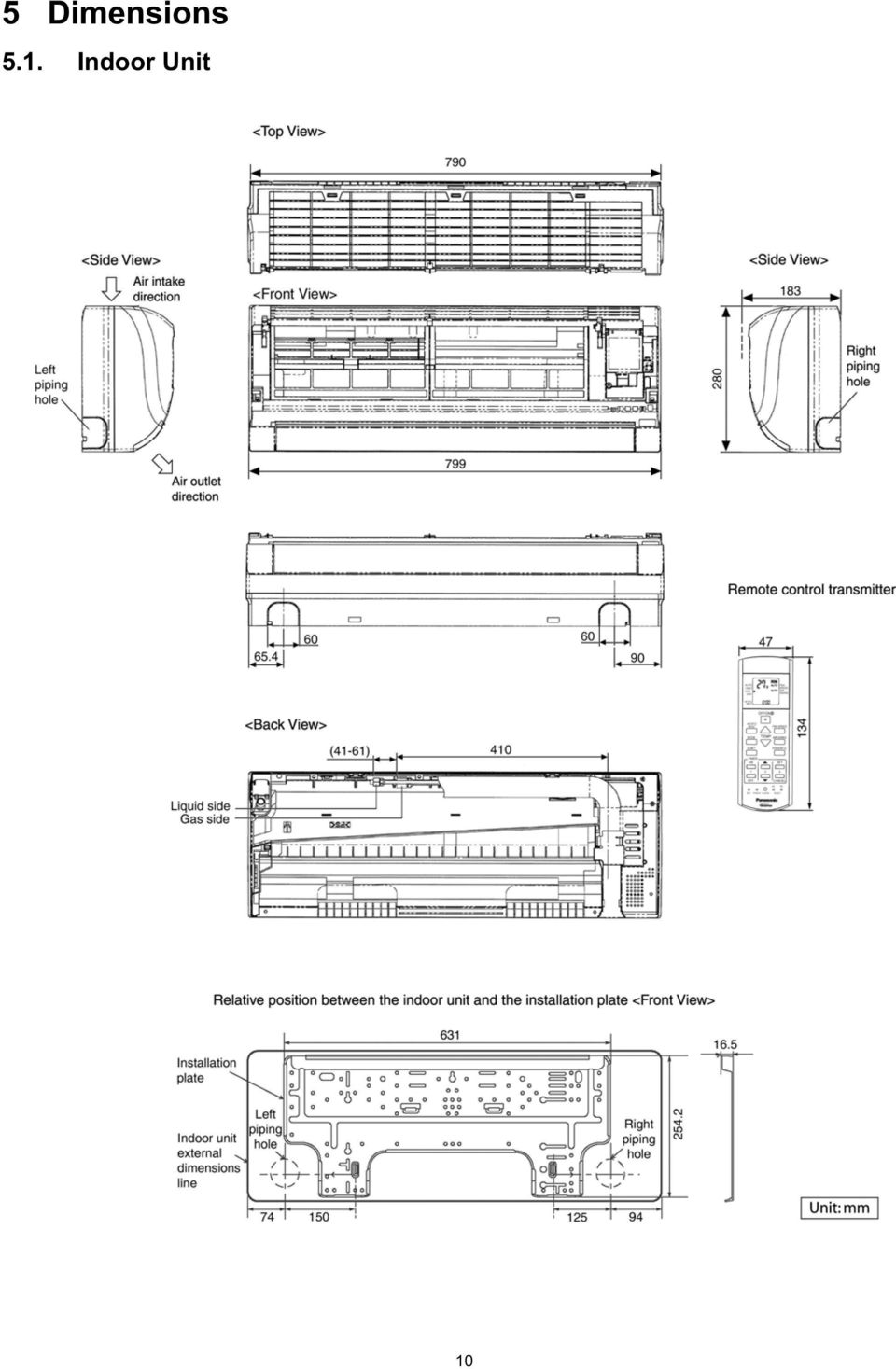
10 5 Dimensions 5.1. Indoor Unit 10
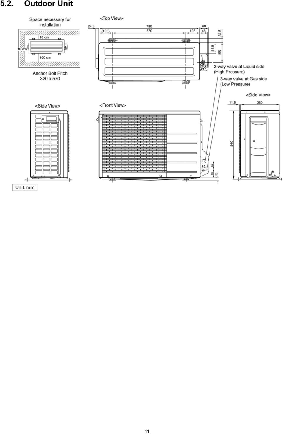
11 5.2. Outdoor Unit 11
12 6 Refrigeration Cycle Diagram Model Gas Piping size Liquid Rated Length (m) Common Length (m) Max. Elevation (m) Max. Piping Length (m) Additional Refrigerant (g/m) E9HKEA 3/8 1/ E12HKEA 1/2 1/ If piping length is over common length, additional refrigerant should be added as shown in the table. 12

13 7 Block Diagram 13

14 8 Wiring Connection Diagram 8.1. Indoor Unit 14

15 8.2. Outdoor Unit 15

16 9 Electronic Circuit Diagram 9.1. Indoor Unit 16

17 9.2. Outdoor Unit 17

18 10 Printed Circuit Board Indoor Unit Main Printed Circuit Board 18

19 Power Printed Circuit Board Indicator Panel 19

20 10.2. Outdoor Unit Main Printed Circuit Board 20

21 11 Installation Instruction Select The Best Location INDOOR UNIT Do not install the unit in excessive oil fume area such as kitchen, workshop and etc. There should not be any heat source or steam near the unit. There should not be any obstacles blocking the air circulation. A place where air circulation in the room is good. A place where drainage can be easily done. A place where noise prevention is taken into consideration. Do not install the unit near the door way. Ensure the spaces indicated by arrows from the wall, ceiling, fence or other obstacles. Recommended installation height for indoor unit shall be at least 2.5 m Indoor/Outdoor Unit Installation Diagram OUTDOOR UNIT If an awning is built over the unit to prevent direct sunlight or rain, be careful that heat radiation from the condenser is not obstructed. There should not be any animal or plant which could be affected by hot air discharged. Keep the spaces indicated by arrows from wall, ceiling, fence or other obstacles. Do not place any obstacles which may cause a short circuit of the discharged air. If piping length is over the rated length, additional refrigerant should be added as shown in the table. Piping size Rated Length (m) Max. Elevation (m) Min. Piping Length (m) Max. Piping Length (m) Additional Refrigerant (g/m) Model Gas Liquid E9HKEA 3/8 1/ E12HKEA 1/2 1/ Example: For E9HKEA If the unit is installed at 10 m distance, the quantity of additional refrigerant should be 50g... (10-7.5) m x 20 g/m = 50 g 21
22 11.3. Indoor Unit HOW TO FIX INSTALLATION PLATE The mounting wall is strong and solid enough to prevent it from the vibration TO DRILL A HOLE IN THE WALL AND INSTALL A SLEEVE OF PIPING 1. Insert the piping sleeve to the hole. 2. Fix the bushing to the sleeve. 3. Cut the sleeve until it extrudes about 15 mm from the wall. The centre of installation plate should be at more than 450 mm at right and left of the wall. The distance from installation plate edge to ceiling should more than 67 mm. From installation plate left edge to unit s left side is 74 mm. From installation plate right edge to unit s right is 94 mm. Caution When the wall is hollow, please be sure to use the sleeve for tube ass y to prevent dangers caused by mice biting the connecting cable. 4. Finish by sealing the sleeve with putty or caulking compound at the final stage. : For left side piping, piping connection for liquid should be about 15 mm from this line. : For left side piping, piping connection for gas should be about 45 mm from this line. : For left side piping, piping connection cable should be about 800 mm from this line. 1. Mount the installation plate on the wall with 5 screws or more. (If mounting the unit on the concrete wall, consider using anchor bolts.) Always mount the installation plate horizontally by aligning the marking-off line with the thread and using a level gauge. 2. Drill the piping plate hole with ø70 mm hole-core drill. Line according to the left and right side of the installation plate. The meeting point of the extended line is the centre of the hole. Another method is by putting measuring tape at position as shown in the diagram above. The hole centre is obtained by measuring the distance namely 150 mm and 125 mm for left and right hole respectively. Drill the piping hole at either the right or the left and the hole should be slightly slanted to the outdoor side INDOOR UNIT INSTALLATION 1. For the right rear piping 2. For the right and right bottom piping 22
23 3. For the embedded piping (This can be used for left rear piping and left bottom piping also.) 23
24 CONNECT THE CABLE TO THE INDOOR UNIT 1. The inside and outside connecting cable can be connected without removing the front grille. 2. Connecting cable between indoor unit and outdoor unit shall be approved polychloroprene sheathed mm 2 flexible cord, type designation 245 IEC 57 or heavier cord. Ensure the colour of wires of outdoor unit and the terminal Nos. are the same to the indoor s respectively. Earth lead wire shall be longer than the other lead wires as shown in the figure for the electrical safety in case of the slipping out of the cord from the anchorage. Secure the cable onto the control board with the holder (clamper). WIRE STRIPPING AND CONNECTING REQUIREMENT 24
25 11.4. Outdoor Unit INSTALL THE OUTDOOR UNIT After selecting the best location, start installation according to Indoor/Outdoor Unit Installation Diagram. 1. Fix the unit on concrete or rigid frame firmly and horizontally by bolt nut (ø10 mm). 2. When installing at roof, please consider strong wind and earthquake. Please fasten the installation stand firmly with bolt or nails. Model A B C D E9HKEA, E12HKEA 570 mm 105 mm 18.5 mm 320 mm CONNECTING THE PIPING Connecting The Piping To Indoor Unit Please make flare after inserting flare nut (locate at joint portion of tube assembly) onto the copper pipe (in case of using long piping). Connect the piping Align the center of piping and sufficiently tighten the flare nut with fingers. Further tighten the flare nut with torque wrench in specified torque as stated in the table. Model Piping size (Torque) Gas Liquid E9HKEA 3/8 [42 N m] 1/4 [18 N m) E12HKEA 1/2 [55 N m] 1/4 [18 N m) Connecting The Piping To Outdoor Unit Decide piping length and then cut by using pipe cutter. Remove burrs from cut edge. Make flare after inserting the flare nut (locate at valve) onto the copper pipe. Align center of piping to valves and then tighten with torque wrench to the specified torque as stated in the table. CUTTING AND FLARING THE PIPING 1. Please cut using pipe cutter and then remove the burrs. 2. Remove the burrs by using reamer. If burrs is not removed, gas leakage may be caused. Turn the piping end down to avoid the metal powder entering the pipe. 3. Please make flare after inserting the flare nut onto the copper pipes. Do not over tighten, over tightening cause gas leakage. 25
26 EVACUATION OF THE EQUIPMENT WHEN INSTALLING AN AIR CONDITIONER, BE SURE TO EVACUATE THE AIR INSIDE THE INDOOR UNIT AND PIPES in the following procedure. 1. Connect a charging hose with a push pin to the Low side of a charging set and the service port of the 3-way valve. Be sure to connect the end of the charging hose with the push pin to the service port. 2. Connect the center hose of the charging set to a vacuum pump with check valve, or vacuum pump and vacuum pump adaptor. 3. Turn on the power switch of the vacuum pump and make sure that the needle in the gauge moves from 0 cmhg (0 MPa) to -76 cmhg (-0.1 MPa). Then evacuate the air approximately ten minutes. 4. Close the Low side valve of the charging set and turn off the vacuum pump. Make sure that the needle in the gauge does not move after approximately five minutes. Note: BE SURE TO FOLLOW THIS PROCEDURE IN ORDER TO AVOID REFRIGERANT GAS LEAKAGE. 5. Disconnect the charging hose from the vacuum pump and from the service port of the 3-way valve. 6. Tighten the service port caps of the 3-way valve at a torque of 18 N m with a torque wrench. 7. Remove the valve caps of both of the 2-way valve and 3-way valve. Position both of the valves to OPEN using a hexagonal wrench (4 mm). 8. Mount valve caps onto the 2-way valve and the 3-way valve. Be sure to check for gas leakage. CAUTION If gauge needle does not move from 0 cmhg (0 MPa) to -76 cmhg (-0.1 MPa), in step above take the following measure: If the leak stops when the piping connections are tightened further, continue working from step. If the leak does not stop when the connections are retightened, repair the location of leak. Do not release refrigerant during piping work for installation and reinstallation. Take care of the liquid refrigerant, it may cause frostbite CONNECT THE CABLE TO THE OUTDOOR UNIT (FOR DETAIL REFER TO WIRING DIAGRAM AT UNIT) 1. Remove the control board cover from the unit by loosening the screw. 2. Connecting cable between indoor unit and outdoor unit shall be approved polychloroprene sheathed 5 x 1.5 mm 2 flexible cord, type designation 245 IEC 57 or heavier cord. 3. Secure the cable onto the control board with the holder (clamper). 4. Attach the control board cover back to the original position with the screw. 5. For wire stripping and connection requirement, refer to page
27 PIPE INSULATION 1. Please carry out insulation at pipe connection portion as mentioned in Indoor/Outdoor Unit Installation Diagram. Please wrap the insulated piping end to prevent water from going inside the piping. 2. If drain hose or connecting piping is in the room (where dew may form), please increase the insulation by using POLY-E FOAM with thickness 6 mm or above. 27
28 12 Operation and Control Basic Function Inverter control, which equipped with a microcomputer in determining the most suitable operating mode as time passes, automatically adjusts output power for maximum comfort always. In order to achieve the suitable operating mode, the microcomputer maintains the set temperature by measuring the temperature of the environment and performing temperature shifting. The compressor at outdoor unit is operating following the frequency instructed by the microcomputer at indoor unit that judging the condition according to internal setting temperature and intake air temperature Internal Setting Temperature Once the operation starts, remote control setting temperature will be taken as base value for temperature shifting processes. These shifting processes are depending on the air conditioner settings and the operation environment. The final shifted value will be used as internal setting temperature and it is updated continuously whenever the electrical power is supplied to the unit Airflow Direction 1. There are two types of airflow, vertical airflow (directed by horizontal vane) and horizontal airflow (directed by vertical vanes). 2. Control of airflow direction can be automatic (angles of direction is determined by operation mode, heat exchanger temperature and intake air temperature) and manual (angles of direction can be adjusted using remote control) Vertical Airflow Operation Mode Airflow Direction Vane Angle ( ) Heating Cooling, Soft Dry and Ion Mode Judgment in Auto A Upward fix 3 Auto with Heat Exchanger B Downward fix 64 Temperature C Upward fix 3 D Downward fix 3 Manual Auto 8 ~ 36 Manual Auto 8 Manual Automatic vertical airflow direction can be set using remote control; the vane swings up and down within the angles as stated above. For heating mode operation, the angle of the vane depends on the indoor heat exchanger temperature as Figure 1 below. When the air conditioner is stopped using remote control, the vane will shift to close position. 2. Manual vertical airflow direction can be set using remote control; the angles of the vane are as stated above and the positions of the vane are as Figure 2 below. When the air conditioner is stopped using remote control, the vane will shift to close position. 28
29 Horizontal Airflow 1. Automatic horizontal airflow direction can be set using remote control; the vane swings left and right within the angles as stated below. For heating mode operation, the angle of the vane depends on the indoor heat exchanger temperature as Figure 1 below. Operation Mode Vane Angle ( ) A 65 ~ 115 Heating, with heat exchanger temperature B 90 Cooling, Soft Dry and Ion 65 ~ Manual horizontal airflow direction can be set using remote control; the angles of the vane are as stated below and the positions of the vane are as Figure 2 above. Pattern Airflow Direction Patterns at Remote Control Vane Angle ( ) Quiet operation (Cooling Mode/Cooling area of Dry Mode) A. Purpose To provide quiet cooling operation compare to normal operation. B. Control condition a. Quiet operation start condition When quiet button at remote control is pressed. Quiet LED illuminates. b. Quiet operation stop condition 1. When one of the following conditions is satisfied, quiet operation stops: a. Powerful button is pressed. b. Stop by OFF/ON switch. c. Timer off activates. d. Quiet button is pressed again. 2. When quiet operation is stopped, operation is shifted to normal operation with previous setting. 3. When fan speed is changed, quiet operation is shifted to quiet operation of the new fan speed. 4. When operation mode is changed, quiet operation is shifted to quiet operation of the new mode. 29
30 5. During quiet operation, if timer on activates, quiet operation maintains. 6. After off, when on back, quiet operation is not memorised. C. Control contents 1. Fan speed is changed from normal setting to quiet setting of respective fan speed. This is to reduce sound of Hi, Me, Lo for 3dB. 2. Fan speed for quiet operation is -1 step from setting fan speed Quiet operation (Heating) A. Purpose To provide quiet heating operation compare to normal operation. B. Control condition a. Quiet operation start condition When quiet button at remote control is pressed. Quiet LED illuminates. b. Quiet operation stop condition 1. When one of the following conditions is satisfied, quiet operation stops: a. Powerful button is pressed. b. Stop by OFF/ON switch. c. Timer off activates. d. Quiet button is pressed again. 2. When quiet operation is stopped, operation is shifted to normal operation with previous setting. 3. When fan speed is changed, quiet operation is shifted to quiet operation of the new fan speed. 4. When operation mode is changed, quiet operation is shifted to quiet operation of the new mode, except fan only mode. 5. During quiet operation, if timer on activates, quiet operation maintains. 6. After off, when on back, quiet operation is not memorised. C. Control contents a. Fan Speed manual 1. Fan speed is changed from normal setting to quiet setting of respective fan speed. This is to reduce sound of Hi, Me, Lo for 3dB. 2. Fan speed for quiet operation is -1 step from setting fan speed. 3. Fan Speed Auto Indoor FM RPM depends on pipe temp sensor of indoor heat exchanger Powerful Mode Operation When the powerful mode is selected, the internal setting temperature will shift to achieve the setting temperature quickly. (a) Cooling Operation (b) Soft Dry Operation 30
31 (c) Heating Operation ON Timer Control ON timer can be set using remote control, the unit with timer set will start operate earlier than the setting time. This is to provide a comfortable environment when reaching the set ON time. 60 minutes before the set time, indoor (at fan speed of Lo-) and outdoor fan motor start operate for 30 seconds to determine the indoor intake air temperature and outdoor air temperature in order to judge the operation starting time. From the above judgment, the decided operation will start operate earlier than the set time as shown below OFF Timer Control OFF timer can be set using remote control, the unit with timer set will stop operate at set time Auto Restart Control 1. When the power supply is cut off during the operation of air conditioner, the compressor will re-operate within three to four minutes (there are 10 patterns between 2 minutes 58 seconds and 3 minutes 52 seconds to be selected randomly) after power supply resumes. 2. This type of control is not applicable during ON/OFF Timer setting Ionizer Operation Purpose To provide fresh air effect to users by discharging minus ion to air. Control Condition 31
32 a. Ionizer Only Operation. 1. When air-conditioner unit is at OFF condition (standby) and ION operation button at remote control is pressed. Fan & ionizer on, ION LED illuminates, but power LED maintain off. (1 2) However, fan speed can be adjusted later by customer during this operation. Airflow direction (Horizontal Vane) control: Follow vane direction control at cooling mode. Horizontal vane can be changed by customer during ion only operation. b. Operation Mode + Ionizer Operation. 1. Ionising Operation Start Condition When air conditioner unit is in ON condition (Heat, Cool, Dry, Auto mode) and ION operation button at remote control is pressed. Ionizer on & ION LED illuminates. (3 4) Power LED also illuminates. 2. Ionising Operation Stop Condition When one of the following condition is satisfied, ION operation stops. a. Stopped by ON/OFF switch. b. Timer OFF activates. c. ION feedback signal shows error. 3. Ionizer operation status is not memorised by micon. After OFF, when operation is ON again, air conditioner operates without ionizer operation Protection Control Time Delay Safety Control Compressor will not start for three minutes after stop of the operation Seconds Forced Operation Once compressor starts the operation, it will not stop its operation for 30 seconds. However, it can be stopped with the remote controller or the Auto button on the indoor unit Total Running Current Control 1. When the total running current exceeds l1, compressor operation frequency is reduced. If it reaches below l1, the operation frequency is increased. (But, up to programmed frequency.) 2. If total running current exceeds l2, compressor is stopped immediately. 3. If it happens three (3) times within 20 minutes, operation will be stopped and Timer LED blinks. ( F98 is activating.) Cooling Heating Running current CS-E9HKEA CS-E12HKEA l1 3.7A 5.8A I2 25.0A 25.0A I1 5.9A 8.2A I2 25.0A 25.0A IPM (Power transistor) Protection Control (DC Peak detection) Abnormal Current Control If inverter load current (DC peak) exceeds a rated value, compressor will be stopped immediately. When the excess occurs within 30 seconds after operation, it restarts in 1 minute and when after 30 seconds, restarts in 2 minutes. If the excess continuously occurs 7 times within 30 minutes after compressor starts, the unit will be stopped and timer LED on the indoor unit will be blinking. ( F99 is to be confirmed.) 32
33 IPM Overheating Prevention Control If temperature of IPM exceeds 103 C, compressor will be stopped. It will restart in 2 minutes. Temperature for restarting: 90 C. If the excess occurs 4 times within 30 minutes after compressor starts, the compressor will be stopped and timer LED on the indoor unit will be blinking. ( F96 is to be confirmed.) Compressor Overheating Prevention Control 1. If discharge pipe temperature exceeds 100 C, compressor power will be limited. 2. If discharge pipe temperature exceeds 112 C, compressor will be stopped. 3. If the above excess occurs 4 times per 10 minutes, timer LED will be blinking. ( F97 is to be confirmed.) Outdoor High Pressure Prevention Control (Cooling and Dry operations) 1. If outdoor heat exchanger temperature exceeds 63 C in cooling or dry operation, compressor will be stopped. 2. Timer LED is not blinking. ( F95 is memorized, then.) Compressor Protection Control (Refrigeration Cycle Abnormality) In cooling and Dry operations 1. When compressor is operated continuously for 5 minutes in the maximum cooling power: a running current of A and [Indoor intake air temperature] - [Indoor heat exchanger temperature] < 4 C, compressor will be stopped. 2. If the above excess occurs twice for 20 minutes, timer LED is to be blinking. ( F91 is to be confirmed.) In Heating operation 1. When compressor is operated continuously for 5 minutes in the rated heating power: a running current of A and [Indoor heat exchanger temperature] - [Indoor intake air temperature] < 5 C, compressor will be stopped. 2. If the above excess occurs twice for 20 minutes, timer LED is to be blinking. ( F91 is to be confirmed.) Four-way Valve Operation Detection Control (Switching Abnormality between Cooling and Heating) In Cooling operation 1. When indoor heat exchanger temperature exceeds 45 C in 4 minutes after compressor starts, compressor will be stopped. 2. If the above excess occurs 4 times per 30 minutes, timer LED is to be blinking. ( F11 is to be confirmed.) In Heating operation 1. When indoor heat exchanger temperature is below 0 C in 4 minutes after compressor starts, compressor will be stopped. 2. If the above excess occurs 4 times per 30 minutes, timer LED is to be blinking. ( F11 is to be confirmed.) Anti-Freezing Control (Cooling and Dry operations) Limit of Cooling power 1. When temperature of indoor heat exchanger is below 5 C, operating frequency will be decreased. 2. When temperature of indoor heat exchanger exceeds 7 C, operating frequency will be increased. (But, up to programmed frequency.) 3. When temperature of indoor heat exchanger is below 0 C continuously for 6 minutes, compressor will be stopped. 4. Timer LED is not blinking. ( F99 is memorized, then.) Limit of Indoor fan speed When temperature of indoor heat exchanger is below 6 C (2 C at Dry) continuously for 6 minutes, indoor fan speed will be increased by 50 rpm Outdoor Air Temperature Control In Cooling and Dry operations 1. When outdoor air temperature is below 25 C, the maximum power will be limited up to about % of the rated power. 2. When outdoor air temperature is below 18 C, the maximum power will be limited up to about % of the rated power. 3. When outdoor air temperature is below 11 C, the maximum power will be limited up to about 26-81% of the rated power Indoor Intake Air Temperature Control (Heating operation) 1. When indoor air temperature is 35 C or more, the maximum power will be limited up to the rated power. 2. When fan speed is set at Lo and intake air temperature is below 21 C, the maximum power will be limited up to the rated power. 33
34 13 Servicing Mode Auto Switch Operation The below operations will be performed by pressing the AUTO switch. 1. AUTO OPERATION MODE The Auto operation will be activated immediately once the Auto Switch is pressed and release before 5 sec.. 2. TEST RUN OPERATION (FOR PUMP DOWN/SERVICING PURPOSE) The Test Run operation will be activated if the Auto Switch is pressed continuously for more than 5 sec. to below 8 sec.. A beep sound will occur at the fifth sec., in order to identify the starting of Test Run operation. 3. HEATING TRIAL OPERATION Press the AUTO switch continuously for more than 8 sec. to below 11 sec. and release when a beep, beep sound is heard at eight sec. (However, a beep sound is occurred at fifth sec.) then press remote controller A/C Reset button once. Remote controller signal will activate operation to force heating mode. 4. REMOTE CONTROLLER RECEIVING SOUND ON/OFF The ON/OFF of remote controller receiving sound can be change over by following steps: a. Press the AUTO switch continuously for more than 16 sec. to below 21 sec. a beep, beep, beep, beep sound will occur at the sixteenth sec.. b. Press the A/C Reset button once. Remote controller signal will activate the remote controller sound setting mode. c. Press the Check button once at remote controller. A beep sound will occur. d. Press the AUTO switch once to select remote controller receiving sound ON/OFF. A beep sound indicates receiving sound ON, and a long beep sound indicates receiving sound OFF Indicator Panel LED POWER TIMER QUIET POWERFUL ION ALLERGEN BUSTER Color Green Orange Orange Orange Green Blue Light ON Operation ON Timer Setting ON Quiet Mode ON Powerful Mode ON Ion Mode ON Operation ON Light OFF Operation OFF Timer Setting OFF Quiet Mode OFF Powerful Mode OFF Ion Mode OFF Operation OFF Note: If POWER LED is blinking, the possible operations of the unit are Hot Start, during Deice operation, operation mode judgment, or ON timer sampling. If Timer LED is blinking, there is an abnormality operation occurs. If Ionizer, LED is blinking, there is an abnormality of Ionizer occurs. 34
35 14 Troubleshooting Guide Refrigeration Cycle System In order to diagnose malfunctions, make sure that there are no electrical problems before inspecting the refrigeration cycle. Such problems include insufficient insulation, problem with the power source, malfunction of a compressor and a fan. The normal outlet air temperature and pressure of the refrigeration cycle depends on various conditions, the standard values for them are shown in the table to the right. 35
36 14.2. Relationship Between The Condition Of The Air Conditioner And Pressure And Electric Current Cooling Mode Heating Mode Condition of the air conditoner Low Pressure High Pressure Electric current during operation Low Pressure High Pressure Electric current during operation Insufficient refrigerant (gas leakage) Clogged capillary tube or Strainer Short circuit in the indoor unit Heat radiation deficiency of the outdoor unit Inefficient compression Carry on the measurements of pressure, electric current, and temperature fifteen minutes after an operation is started Breakdown Self Diagnosis Function Once abnormality detected during operation, the unit will immediately stop its operation (Timer LED is blinking) and maximum of three error codes (abnormality) will be saved in memory. The abnormality of the operation can be identified through the below breakdown diagnosis method: Press CHECK button at remote controller continuously for more than five seconds to turn on the diagnosis mode, H11 will be displayed at remote controller. By pressing the TMER button once, next error code will be displayed; press V button once, previous error code will be displayed. If error code displayed matches the error code saved in unit memory (abnormality detected), beep, beep, beep... sounds will be heard for 4 seconds and Power LED will light on. Otherwise, one beep sound is heard. If CHECK button is press again or without any operation for 30 seconds, the diagnosis mode will turn off. 36
37 14.4. Error Codes Table Diagnosis display Abnormality / Protection control Abnormality Judgement Emergency operation Primary location to verify H00 No abnormality detected Normal operation H11 Indoor / outdoor abnormal communication > 1 min after starting operation Indoor fan operation only Internal / external cable connections Indoor / Outdoor PCB H12 Connection capability rank abnormal H14 H15 Indoor intake air temperature sensor abnormality Outdoor compressor temperature sensor abnormality Continue for 5 sec. Continue for 5 sec. H16 Outdoor Current Transformer open circuit H19 Indoor fan motor merchanism locked H23 Indoor heat exchanger temperature sensor abnormality Continue for 5 sec. O (Cooling only) Intake air temperature sensor (detective or disconnected) Compressor temperature sensor (detective or disconnected) Outdoor PCB IPM (Power transistor) module Indoor PCB Fan motor H26 Ionizer breakdown Ionizer H27 H28 H30 Outdoor intake air temperature sensor abnormality Outdoor heat exchanger temperature sensor abnormality Outdoor discharge air temperature sensor abnormality Continue for 5 sec. Continue for 5 sec. O O Continue for 5 sec. Heat exchanger temperature sensor (defective or disconnected) Outdoor temperature sensor (defective or disconnected) Outdoor heat exchanger temperature sensor (defective or disconnected) Outdoor temperature sensor (defective or disconnected) H33 Indoor/Outdoor wrong connection Indoor/Outdoor supply voltage H38 Indoor / outdoor mismatch (brand code) H97 Outdoor fan motor mechanism locked 2 times occurance within 30 minutes H98 Indoor high pressure protection H99 F11 F90 F91 Indoor heat exchanger anti-freezing protection Cooling / Heating cycle changeover abnormality PFC control Refrigeration cycle abnormality 4 times occurance within 30 minutes 4 times occurance within 10 minutes 2 times occurance within 20 minutes Indoor PCB Fan motor Air filter dirty Air circulation short circuit Insufficient refrigerant Air filter dirty 4-way valve V-coil Voltage at PFC No refrigerant (3-way valve is closed) F93 Compressor rotation failure Compressor F95 F96 F97 F98 F99 Cool high pressure protection IPM (power transistor) overheating protection Outdoor compressor overheating protection Total running current protection Outdoor Direct Current (DC) peak detection 4 times occurance within 20 minutes 4 times occurance within 10 minutes 3 times occurance within 20 minutes 7 times occurance continuously Outdoor refrigerant circuit Excess refrigerant Improper heat radiation IPM (Power transistor) Insufficient refrigerant Compressor Excess refrigerant Improper heat radiation Outdoor PCB IPM (Power transistor) Compressor Note: O - Frequency measured and fan speed fixed. The memory data of error code is erased when the power supply is cut off, or press the Auto Switch until beep sound heard following by pressing the RESET button at remote controller. Although operation forced to stop when abnormality detected, emergency operation is possible for certain errors (refer to Error Codes Table) by using remote controller or Auto Switch at indoor unit. However, the remote controller signal receiving sound is changed from one beep to four beep sounds. 37
38 15 Disassembly and Assembly Instructions Caution! When handling electronic controller, be careful of electrostatic discharge. Be sure to return the wiring to its original position. There are many high voltage components within the heat sink cover so never touch the interior during operation. Wait at least two minutes after power has been turned off Indoor Electronic Controller and Control Board 38
39 39
40 15.2. Indoor Cross Flow Fan and Fan Motor 40
41 41
42 15.3. Outdoor Electronic Controller Removal Procedure Caution! When handling electronic controller, be careful of electrostatic discharge. 1. Remove the 3 screws of the Top Panel. 5. Remove the Control Board as follows: Fig Remove the 6 screws of the Front Panel. Fig. 4 Fig Remove the screw of the Terminal Board Cover. 4. Remove the Top Cover of the Control Board by 4 hooks. Fig. 5 Fig. 6 Fig. 3 42
43 16 Technical Data Operation Characteristics CS-E9HKEA CU-E9HKEA 43
44 44
45 45
46 46
47 CS-E12HKEA CU-E12HKEA 47
48 48
49 49
50 50
51 16.2. Sensible Capacity Chart CS-E9HKEA CU-E9HKEA 230V Outdoor Temp. ( C) Indoor wet bulb temp. TC SHC IP TC SHC IP TC SHC IP TC SHC IP 17.0 C C C C CS-E12HKEA CU-E12HKEA 230V Outdoor Temp. ( C) Indoor wet bulb temp. TC SHC IP TC SHC IP TC SHC IP TC SHC IP 17.0 C C C C TC SHC IP Total Cooling Capacity (kw) Sensible Heat Capacity (kw) Input Power (kw) Indoor 27 C/19 C Outdoor 35 C/24 C 51
52 17 Exploded View and Replacement Parts List Indoor Unit Note The above exploded view is for the purpose of parts disassembly and replacement. The non-numbered parts are not kept as standard service parts. 52
53 REF. NO. PART NAME & DESCRIPTION QTY. CS-E9HKEA CS-E12HKEA REMARKS 1 CHASSY COMPLETE 1 CWD50C FAN MOTOR 1 ARW61F8P30AC O 3 CROSS FLOW FAN COMPLETE 1 CWH02C BEARING ASSY 1 CWH64K007 5 SCREW - CROSS FLOW FAN 1 CWH EVAPORATOR CO. 1 CWB30C2405 CWB30C FLARE NUT (1/4) 1 CWT FLARE NUT (3/8) (1/2) 1 CWT CWT CLIP FOR SENSOR 1 CWH DISCHARGE GRILLE COMPLETE 1 CWE20C VERTICAL VANE 9 CWE CONNECTING BAR 1 CWE A.S.MOTOR, DC SINGLE 12V CWA98260+MJ O 14 LEADWIRE CO - AIR SWING MOTOR 1 CWA67C CAP - DRAIN TRAY 1 CWH HORIZONTAL VANE 1 CWE BACK COVER CHASSIS 1 CWD CONTROL BOARD CASING 1 CWH TERMINAL BOARD COMPLETE 1 CWA28C2306 O 20 P.S CORD COMPLETE 1 CWA20C ELECTRONIC CONTROLLER - MAIN 1 CWA73C3230 CWA73C3231 O 22 LEAD WIRE - AIR SWING MOTOR 1 CWA67C3849 O 23 ELECTRONIC CONTROLLER - POWER 1 CWA SENSOR COMPLETE 1 CWA50C2404 O 25 CONTROL BOARD FRONT COVER 1 CWH INDICATOR COMPLETE 1 CWE39C1126 O 27 INDICATOR HOLDER 1 CWD INDICATOR HOLDER 1 CWD CONTROL BOARD FRONT COVER CO. 1 CWH13C REMOTE CONTROL COMPLETE 1 CWA75C3192 O 31 FRONT GRILLE CO. 1 CWE11C3973 O 32 INTAKE GRILLE COMPLETE 1 CWE22C GRILLE DOOR 1 CWE14C AIR FILTER 2 CWD SCREW - FRONT GRILLE 2 XTT4+16CFJ 36 CAP - FRONT GRILLE 2 CWH DRAIN HOSE 1 CWH INSTALLATION PLATE 1 CWH BAG COMP. - INSTALLATION SCREW 1 CWH82C FULCRUM 1 CWH ELECTRONIC CONTROLLER - IONIZER 1 CWA CWH91C1013 O 42 CASING - IONIZER 1 CWD CWA CASING - IONIZER 1 CWD CWD00C ION GENERATOR 1 CWH94C SUPERSONIC AIR PURIFYING DEVICE 1 CWH91C ELEC. CONTROLLER - SUPERSONIC 1 CWA O 47 SUPER ALLERU BUSTER FILTER 1 CWD00C FRAME FR AIR FILTER SUPERSONIC 1 CWD FRAME FR AIR FILTER SUPERSONIC 1 CWD OPERATION INSTRUCTION 1 CWF OPERATION INSTRUCTION 1 CWF INSTALLATION INSTRUCTION 1 CWF INSTALLATION INSTRUCTION 1 CWF INSTALLATION INSTRUCTION 1 CWF
CS-XE9EKE CU-XE9EKE CS-XE12EKE CU-XE12EKE
 Order No. MAC0512111C8 Air Conditioner CS-XE9EKE CU-XE9EKE CS-XE12EKE CU-XE12EKE TABLE OF CONTENTS PAGE 1 Safety Precautions----------------------------------------------- 3 2 Specifications -----------------------------------------------------
TABLE OF CONTENTS. Air Conditioner. Indoor Unit Outdoor Unit CS-NE9MKE CU-NE9MKE CS-NE12MKE CU-NE12MKE CS-XE9MKE-5 CU-NE9MKE CS-XE12MKE-5 CU-NE12MKE
 Order No. PHAAM1107134C2 Air Conditioner Indoor Unit Outdoor Unit CS-NE9MKE CU-NE9MKE CS-NE12MKE CU-NE12MKE CS-XE9MKE-5 CU-NE9MKE CS-XE12MKE-5 CU-NE12MKE TABLE OF CONTENTS PAGE 1 Safety Precautions-----------------------------------------------
CS-CE9NKE CS-CE12NKE CU-CE9NKE CU-CE12NKE TABLE OF CONTENTS WARNING
 Order No: PAPAMY1207094CE Indoor Unit CS-CE9NKE CS-CE12NKE Outdoor Unit CU-CE9NKE CU-CE12NKE WARNING This service information is designed for experienced repair technicians only and is not designed for
CU-2E15LBE CU-2E18LBE CU-3E18LBE CU-4E23LBE
 Order No. PHAAM1003090C3 Outdoor Unit CU-2E15LBE CU-2E18LBE CU-3E18LBE CU-4E23LBE Air Conditioner Please file and use this manual together with the service manual for Model No. CS-E7LKEW CU-E7LKE CS-E7LKEW
CU-S9KKQ CU-S12KKQ CU-S18KKQ CU-S24KKQ CS-S9KKQ CS-S12KKQ CS-S18KKQ CS-S24KKQ WARNING
 Order No: PHAAM1001037C3 Indoor Unit CS-S9KKQ CS-S12KKQ CS-S18KKQ CS-S24KKQ Outdoor Unit CU-S9KKQ CU-S12KKQ CU-S18KKQ CU-S24KKQ WARNING This service information is designed for experienced repair technicians
CS-HE9NKE CS-HE12NKE CS-AE9NKE CU-HE9NKE CU-HE12NKE CU-AE9NKE TABLE OF CONTENTS WARNING
 Order No: PAPAMY1207093CE Indoor Unit CS-HE9NKE CS-HE12NKE CS-AE9NKE Outdoor Unit CU-HE9NKE CU-HE12NKE CU-AE9NKE WARNING This service information is designed for experienced repair technicians only and
14. Troubleshooting Guide
 14. Guide 14.1 Refrigeration Cycle System In order to diagnose malfunctions, ensure the air conditioner is free from electrical problems before inspecting the refrigeration cycle. Such problems include
Air Conditioner CU-XE9PKUA CU-XE12PKUA CS-XE9PKUA CS-XE12PKUA. Destination U.S.A. Canada WARNING
 Order No: PAPAMY1305056CE Air Conditioner Indoor Unit CS-XE9PKUA CS-XE12PKUA Outdoor Unit CU-XE9PKUA CU-XE12PKUA Destination U.S.A. Canada WARNING This service information is designed for experienced repair
Split-type Air-Conditioner INSTALLATION MANUAL CONTENTS FOR INSTALLER MXZ-3A30NA MXZ-4A36NA ATTENTION. English. Français. Español
 Split-type Air-Conditioner MXZ-3A30NA MXZ-4A36NA INSTALLATION MANUAL Refer to the installation manual of each indoor unit for indoor unit installation. English Français Español ATTENTION This manual mentions
Operating Instructions Air Conditioner
 F566272 Operating Instructions Air Conditioner CS-C18FFH CS-C28FFH CU-C18FFH CU-C28FFH ENGLISH Before operating the unit, read these operating instructions thoroughly and keep them for future reference.
Air Conditioner CONTENTS CS-TE9DKE CU-TE9DKE CS-TE12DKE CU-TE12DKE. Order No. RAC0502005C2
 Order No. RAC0502005C2 Air Conditioner CS-TE9DKE CU-TE9DKE CS-TE12DKE CU-TE12DKE CONTENTS Page Page 1 Features 2 2 Functions 3 2.1. Remote Control 3 2.2. Indoor Unit 4 2.3. Outdoor unit 5 3 Product Specifications
Air Conditioner CONTENTS CS-V7DKE CU-V7DKE CS-V9DKE CU-V9DKE CS-V12DKE CU-V12DKE. Order No. MAC0412062C2
 Order No. MAC0412062C2 CS-V7DKE CU-V7DKE CS-V9DKE CU-V9DKE CS-V12DKE CU-V12DKE Air Conditioner CONTENTS Page Page 1 Features 3 2 Functions 4 2.1. Remote Control 4 2.2. Indoor Unit 5 2.3. Outdoor Unit 6
WH-UD09CE8 WH-UD12CE8 WH-UD14CE8 WH-UD16CE8 WH-SDF09C3E8 WH-SDF12C9E8 WH-SDF14C9E8 WH-SDF16C9E8 WARNING
 Order No. PHAAM1009094C2 Indoor Unit WH-SDF09C3E8 WH-SDF12C9E8 WH-SDF14C9E8 WH-SDF16C9E8 Outdoor Unit WH-UD09CE8 WH-UD12CE8 WH-UD14CE8 WH-UD16CE8 WARNING This service information is designed for experienced
Operating Instructions Split System Air Conditioner
 Operating Instructions Split System Air Conditioner Model No. Indoor Unit Type Indoor Unit Type Nominal Capacity 26 36 F2 Low Silhouette Ducted S-26PF2U6 S-36PF2U6 Connectable outdoor unit lineup This
AIR-CONDITIONER SPLIT TYPE
 FILE NO. A08-016 SERVICE MANUAL AIR-CONDITIONER SPLIT TYPE RAS-M10PKVP-E, RAS-M13PKVP-E, RAS-M16PKVP-E, RAS-M18PKVP-E / RAS-M10PKVP-ND, RAS-M13PKVP-ND, RAS-M16PKVP-ND, RAS-M18PKVP-ND / RAS-3M26GAV-E1,
SERVICE MANUAL SPLIT SYSTEM ROOM AIR CONDITIONER SHARP CORPORATION SHARP CORPORATION CONTENTS
 SERVICE MANUAL SPLIT SYSTEM ROOM AIR CONDITIONER INDOOR UNIT AH-129 AH-MP14 OUTDOOR UNIT AU-129 AU-MP14 CONTENTS SPECIFICATIONS...2 EXTERNAL DIMENSIONS...4 WIRING DIAGRAMS...5 ELECTRICAL PARTS...6 MICROCOMPUTER
CS-PE9CKE CU-PE9CKE CS-PE12CKE CU-PE12CKE
 Order No. GMAC0401003C2 CS-PE9CKE CU-PE9CKE CS-PE12CKE CU-PE12CKE Room Air Conditioners CONTENTS Page 1 Functions 2 2 Product Specifications 5 3 Dimensions 9 4 Refrigeration Cycle Diagram 11 5 Block Diagram
TECHNICAL DATA & SERVICE MANUAL SPLIT SYSTEM AIR CONDITIONER INDOOR UNIT: AW52AL AW64AL AW52AL 387030095 AW64AL 0.8180.463.0 07/05
 TECHNICAL DATA & SERVICE MANUAL INDOOR UNIT: AW52AL AW64AL SPLIT SYSTEM AIR CONDITIONER Model No. Product Code No. AW52AL 387030095 AW64AL 387030096 0.8180.463.0 07/05 IMPORTANT! Please read before installation
ROOM AIR CONDITIONER INSTALLATION MANUAL
 ROOM AIR CONDITIONER INSTALLATION MANUAL ( Split Type) Please read this installation manual completely before installing the product When the power cord is damaged, replacement work shall be performed
SERVICE MANUAL. Room Air Conditioner Multi Split Wall-Mounted Type Indoor. FSAI-Pro-91AE2 FSAI-Pro-121AE2 FSAIF-Pro-181AE2
 SERVICE MANUAL Room Air Conditioner Multi Split Wall-Mounted Type Indoor FSAI-Pro-91AE2 FSAI-Pro-121AE2 FSAIF-Pro-181AE2 NOTE: Before servicing the unit, please read this at first. Always contact with
SERVICE INSTRUCTION R410A. WALL MOUNTEDtype INVERTER SPLIT TYPE ROOM AIR CONDITIONER. Models Indoor unit Outdoor unit
 SERVICE INSTRUCTION SPLIT TYPE ROOM AIR CONDITIONER WALL MOUNTEDtype INVERTER Models Indoor unit Outdoor unit ASYG07LECA ASYG09LECA ASYG12LECA ASYG14LECA AOYG07LEC AOYG09LEC AOYG12LEC AOYG14LEC R410A CONTENTS
Floor Type Air-Conditioner INSTALLATION MANUAL CONTENTS FOR INSTALLER MFZ-KA25VA MFZ-KA35VA MFZ-KA50VA. English
 Floor Type Air-Conditioner MFZ-KA25VA MFZ-KA35VA MFZ-KA50VA INSTALLATION MANUAL This manual only describes the installation of indoor unit. When installing the outdoor unit, refer to the installation manual
TECHNICAL & SERVICE MANUAL SPLIT SYSTEM AIR CONDITIONER + SAP C181MA + SAP C181GA + SAP C181BA + SAP C241MA + SAP C241BA FILE NO.
 TECHNICAL & SERVICE MANUAL SAP K161GJA SAP K181GJA SAP K181MBA SAP K241GJA SAP K241MBA + SAP C161GA + SAP C161JA + SAP C181GA + SAP C181JA + SAP C181MA + SAP C181BA + SAP C241GA + SAP C241JA + SAP C241MA
Monobloc Air-to-Water Heatpump System
 Order No. PHAAM1010087C2 Monobloc Air-to-Water Heatpump System Monobloc Unit WH-MDF09C3E8 WH-MDF12C9E8 WH-MDF14C9E8 WH-MDF16C9E8 WARNING This service information is designed for experienced repair technicians
NewAir AC-10000E, AC-10000H Portable Air Conditioner Owner s Manual PLEASE READ AND SAVE THESE INSTRUCTIONS
 NewAir AC-10000E, AC-10000H Portable Air Conditioner Owner s Manual PLEASE READ AND SAVE THESE INSTRUCTIONS BEFORE USE GENERAL SAFETY INSTRUCTIONS: ALWAYS OPERATE THE UNIT IN AN UPRIGHT POSITION AND PLACE
Reverse Cycle Inverter Split System Air Conditioner
 Reverse Cycle Inverter Split System Air Conditioner Model Number TAC-09CHSA/JAI5 INSTALLATION MANUAL Contents 03 Warranty Details 04 Welcome 05 General Safety Instructions 06 Product Overview 07 Selecting
FAN SPEED AIR SWING SET CANCEL FAN AIR SWING SET CANCEL WARNING
 AUT O HE AT COOL DRY AUT O HE AT COOL DRY FAN SP E ED FAN SPEED AC AC AIR SWING SE T CHE CK CLOCK RE SE T AIR SWING SE T CHE CK CLOCK RE SE T FAN SPEED AIR SWING RC RC Order No: PAPAMY32039CE (YE9/2QKE)
CONTENTS 1. IMPORTANT NOTICE 2 2. TECHNICAL SPECIFICATION 3 3. OPERATION DETAILS 4 4. WIRING DIAGRAM 11 5. EXPLOSION VIEW 12 6.
 TCL WALL MOUNTED SPLIT-TYPE AIR CONDITIONERS SERVICE MANUAL No.TE051220 Models TAC-09CHSA/GI TAC-12CHSA/GI CONTENTS 1. IMPORTANT NOTICE 2 2. TECHNICAL SPECIFICATION 3 3. OPERATION DETAILS 4 4. WIRING DIAGRAM
ENGLISH INSTRUCTION & INSTALLATION MANUAL DUCTLESS MINI SPLIT AIR CONDITIONING SYSTEMS
 ENGLISH INSTRUCTION & INSTALLATION MANUAL DUCTLESS MINI SPLIT AIR CONDITIONING SYSTEMS Céliera Corporation. All rights reserved. Unauthorized duplication, reproduction prohibited. CONTENTS SAFETY PRECAUTIONS...
Operating Instructions Air Conditioner
 P07-T10130 Operating Instructions Air Conditioner Indoor Unit CS-F24DD1E5 CS-F28DD1E5 CS-F34DD1E5 CS-F43DD1E5 CS-F50DD1E5 Outdoor Unit Inverter Model (HBE5 Series) CU-YL24HBE5 CU-YL28HBE5 CU-YL34HBE5 CU-YL43HBE5
LG Floor Standing Type Air Conditioner INSTALLATION MANUAL
 website http://www.lgservice.com e-mail http://www.lgeservice.com/techsup.html LG Floor Standing Type Air Conditioner INSTALLATION MANUAL LG IMPORTANT Please read this installation manual completely before
USER INSTRUCTIONS FOR GET PORTABLE 12k BTU AIR CONDITIONER MODEL No. GPACU12HR
 USER INSTRUCTIONS FOR GET PORTABLE 12k BTU AIR CONDITIONER MODEL No. GPACU12HR CONTENTS Introduction Safety Notes Identification of parts Installation instructions Operation instructions Maintenance Troubleshooting
USER S MANUAL HSC-24A
 AIRREX AIR CONDITIONER USER S MANUAL HSC-24A Thank you for purchasing an AIRREX AIR CONDITIONER. BEFORE operation please read this user s manual carefully. Keep this manual readily available. It is ESSENTIAL
Wall Mounted Mini Split Heat Pump Air Conditioner
 Wall Mounted Mini Split Heat Pump Air Conditioner OPERATING AND INSTALLATION MANUAL Model: KFIHP-09-ID / KFHIP-09-OD KFHHP-12-ID / KFHHP-12-OD Indoor Unit. Outdoor Unit. Thank you for selecting Soleus
SPLIT -TYPE ROOM AIR CONDITIONER
 Before using your air conditioner, please read this manual carefully and keep it for future reference SPLIT -TYPE ROOM AIR CONDITIONER Please read this installation manual completely before installing
WINDOW ROOM AIR CONDITIONER
 WINDOW ROOM AIR CONDITIONER Installation and Operation Manual Electromechanical Remote Control CAPACITIES 220V - 60 HZ. 12,000; 18,000; 24000 BTU/HR 220V-240V - 50 HZ. 12,000; 18,000; 24000 BTU/HR Please
USER INSTRUCTIONS FOR 10 LITRE PORTABLE DEHUMIDIFIER MODEL NO. DHMD102
 USER INSTRUCTIONS FOR 10 LITRE PORTABLE DEHUMIDIFIER MODEL NO. DHMD102 THANK YOU FOR CHOOSING YOUR NEW DEHUMIDIFIER. BEFORE USING THE UNIT READ THESE INSTRUCTIONS FULLY AND RETAIN THEM FOR FUTURE REFERENCE
SERVICE MANUAL OUTDOOR UNIT. No. OBH590 REVISED EDITION-B. Models HFC
 SPLIT-TYPE AIR CONDITIONERS Revision B: MUZ-EF25/35/42/50VE - E2 and MUZ-EF25/35VEH - E2 have been added. Please void OBH590 REVISED EDITION-A. OUTDOOR UNIT SERVICE MANUAL HFC utilized R410A. OBH590 REVISED
CONTENTS 1. IMPORTANT NOTICE 2 2. TECHNICAL SPECIFICATION 3 3. OPERATION DETAILS 4 4. ELECTRICAL SCHEMATIC DIAGRAM 13 5. EXPLOSION VIEW 16 6
 TCL WALL MOUNTED SPLIT-TYPE AIR CONDITIONERS SERVICE MANUAL No.TE080528 Models KFTHP-12 KFTHP-18 KFTHP-24 CONTENTS 1. IMPORTANT NOTICE 2 2. TECHNICAL SPECIFICATION 3 3. OPERATION DETAILS 4 4. ELECTRICAL
TECHNICAL & SERVICE MANUAL WINDOW TYPE AIR CONDITIONER SA 79G SA 99G FILE NO. SA 79G SA 99G REFERENCE NO. SM700402
 TECHNICAL & SERVICE MANUAL SA 79G SA 99G FILE NO. WINDOW TYPE AIR CONDITIONER Model No. Product Code No. Destination SA-79G-A 1 851 005 18 General (50Hz) & Europe SA-99G-A 1 851 005 19 SA 79G SA 99G REFERENCE
Portable Air Conditioner
 Portable Air Conditioner Owner's Manual Model:3 in 1 12,000 Btu/h Series 3 Please read this owner s manual carefully before operation and retain it for future reference. CONTENTS 1. SUMMARY...1 2. PORTABLE
OPTIONAL SLENDER REMOTE CONTROL
 DAIKIN ROOM AIR CONDITIONER Operation Manual OPTIONAL SLENDER REMOTE CONTROL BRC944A2B READ BEFORE OPERATION Safety Precautions...2 Names of Functions of Parts...4 Preparation before Operation...5 OPERATION
Service manual. Website: www.andico.com.au CAUTION - BEFORE SERVICING THE UNIT, READ THE SAFETY - PRECAUTIONS IN THIS MANUAL.
 Website: www.andico.com.au Service manual CAUTION - BEFORE SERVICING THE UNIT, READ THE SAFETY - PRECAUTIONS IN THIS MANUAL. - ONLY FOR AUTHORISED SERVICE PERSONNEL. MODELS: MPK1-09CR-QB8 MPK1-12ER-QB6
AIR CONDITIONER INSTALLATION MANUAL
 FRANCAIS ESPAÑOL INSTALLATION MANUAL AIR CONDITIONER Please read this installation manual completely before installing the product. Installation work must be performed in accordance with the national wiring
SWIMMING POOL HEAT PUMP
 SWIMMING POOL HEAT PUMP Installation & User Manual Model HP40B HP50B HP65B Hayward Pool Products Canada, Inc. T: 1-888-238-7665 www.haywardpool.ca CONTENT I. Application 4 II. Features 4 III. Technical
AIR CONDITIONER INSTALLATION MANUAL
 INSTALLATION MANUAL AIR CONDITIONER Please read this installation manual completely before installing the product. Installation work must be performed in accordance with the national wiring standards by
york air-conditioning products Residential & VRF News 2015
 york air-conditioning products Residential & VRF News 2015 york air-conditioning products Catalogue Content Split Systems Pag. High wall High Efficiency Inverter YWHJZH 09 to 24 K 6 High wall Inverter
SERVICE INSTRUCTION R410A. WALL MOUNTEDtype SPLIT TYPE ROOM AIR CONDITIONER INVERTER. Models Indoor unit Outdoor unit AOU 9RLFW AOU12RLFW AOU15RLS
 SERVICE INSTRUCTION SPLIT TYPE ROOM AIR CONDITIONER WALL MOUNTEDtype INVERTER Models Indoor unit Outdoor unit ASU 9RLF ASURLF ASU5RLS AOU 9RLFW AOURLFW AOU5RLS R40A CONTENTS. DESCRIPTION OF EACH CONTROL
9ASNA-A1-1202 SERVICE MANUAL SENVILLE AIRCONDITIONER DC INVERTER SPLIT WALL-MOUNTED TYPE
 9ASNA-A1-1202 SERVICE MANUAL SENVILLE AIRCONDITIONER DC INVERTER SPLIT WALL-MOUNTED TYPE CONTENTS 1. Precaution... 1 1.1 Safety Precaution... 1 1.2 Warning... 1 2. Function... 6 3. Dimension... 9 3.1 Indoor
SERVICE MANUAL MUZ-GE25VA - E1 MUZ-GE25VAH - E1 MUZ-GE35VA - E1 MUZ-GE35VAH - E1 MUZ-GE42VA - E1 MUZ-GE42VAH - E1 MUZ-GE50VA - E1 MUZ-GE50VAH - E1
 SPLIT-TYPE AIR CONDITIONERS Revision A: MUZ-GE42/50VA(H) - E1 has been added. Please void OBH516. OUTDOOR UNIT SERVICE MANUAL HFC utilized R410A. OBH516 REVISED EDITION-A Models MUZ-GE25VA - E1 MUZ-GE25VAH
Dehumidifier Users manual. For Models: DH45S DH65S
 Dehumidifier Users manual For Models: DH45S DH65S 950-0062-revD Jan. 9 2007 FORWARD The appearance of the units that you purchase might be slightly different from the ones described in the Manual, but
Use and Care Manual. Model CPA12KH AIR CONDITIONER
 Use and Care Manual Model CPA12KH AIR CONDITIONER Introduction Thank you for choosing this air conditioner to provide you and your family with all of the "Home Comfort" requirements for your home, cottage
technical data air conditioning systems RXS20-25-35E (single phase) FBQ-B8V1-B8V3B Split Heat Pump Condensing Units Split Sky Air
 FBQ-B8V1-B8V3B Split Heat Pump Condensing Units Split Sky Air") technical data RXS20-25-35E FBQ-B8V-B8V3B (single phase) Split Heat Pump Condensing Units air conditioning systems Split Sky Air Outdoor Units R-40A RXS-E2VB Split Sky Air Outdoor Units Features O u t
technical data RXS20-25-35E FBQ-B8V-B8V3B (single phase) Split Heat Pump Condensing Units air conditioning systems Split Sky Air Outdoor Units R-40A RXS-E2VB Split Sky Air Outdoor Units Features O u t
Air Conditioners Technical Data
 Air Conditioners Technical Data O u t d o o r U n i t E E D E N 2-0 0 RX-JV Outdoor Unit RX-JV TABLE OF CONTENTS RX-JV Features............................................................. 2 2 Specifications.......................................................
Si10-417_C. Pocket Manual. Service Diagnosis SPLIT & MULTI
 Pocket Manual Service Diagnosis SPLIT & MULTI Service Diagnosis SPLIT & MULTI 1. Troubleshooting with LED...5 1.1 Indoor Unit... 5 1.2 Outdoor Unit... 10 2. Troubleshooting by Symptoms...11 2.1 Air conditioner
NewAir AC-10100E / AC-10100H Portable Air Conditioner Owner s Manual PLEASE READ AND SAVE THESE INSTRUCTIONS
 NewAir AC-10100E / AC-10100H Portable Air Conditioner Owner s Manual PLEASE READ AND SAVE THESE INSTRUCTIONS ELECTRICAL SAFETY This appliance is for indoor use only. Always turn off the unit and unplug
Hi Wall Split Air Conditioners
 R22 220-240V ~, 50Hz Hi Wall Split Air Conditioners 53KHET 12-18-24 Cool Only 53QHET 12-18-24 Heat Pump INSTALLATION MANUAL Carrier is committed to continuously improving its products according to national
CEILING CASSETTE TYPE AIR CONDITIONERS INSTALLATION INSTRUCTIONS
 CEILING CASSETTE TYPE AIR CONDITIONERS INSTALLATION INSTRUCTIONS Please read this instruction sheet completely before installing the product. When the power cord is damaged, replacement work should be
HP switch LP switch Discharge thermo Comp. Surface thermo
 1 Specifications Zubadan Model Name PUHZ-SHW80VHA PUHZ-SHW11VHA PUHZ-SHW11YHA Power supply (phase, cycle, voltage) 1φ, V, Hz 1φ, V, Hz 3φ, 0V, Hz Max. current A 9.5 35.0 13.0 Breaker size A 3 16 Outer
Model: AC-S13CG x 2. Model No: AC-S13CGx2.doc Version 1.0
 Air Conditioner Service Manual 2 3 Model: AC-S13CG x 2 3 Content Technical specification.. 4 Performance curve.5 Outline & dimension of indoor unit..10 Outline & dimension of outdoor unit 11 Exploded view
AIR CONDITIONER (SPLIT TYPE)
") OWNER S MANUAL AIR CONDITIONER (SPLIT TYPE) For general public use ENGLISH EN Indoor Unit RAS-07PKVP-E RAS-10PKVP-E RAS-13PKVP-E RAS-16PKVP-E RAS-18PKVP-E RAS-07PKVP-ND RAS-10PKVP-ND RAS-13PKVP-ND RAS-16PKVP-ND
OWNER S MANUAL AIR CONDITIONER (SPLIT TYPE) For general public use ENGLISH EN Indoor Unit RAS-07PKVP-E RAS-10PKVP-E RAS-13PKVP-E RAS-16PKVP-E RAS-18PKVP-E RAS-07PKVP-ND RAS-10PKVP-ND RAS-13PKVP-ND RAS-16PKVP-ND
PORTABLE AIR CONDITIONER
 PORTABLE AIR CONDITIONER MAC 7500 Owner s Manual Air Conditioner Dehumidifier Oscillating Fan Please read this owner s manual carefully before operating the unit. POWERED BY 66126113.p65 17 INTRODUCTION
AIR CONDITIONER OUTDOOR UNIT
 AIR CONDITIONER OUTDOOR UNIT INSTALLATION MANUAL For authorized personnel only. MANUEL D'INSTALLATION Pour le personnel agréé uniquement. English Français MANUAL DE INSTALACIÓN Solo para personal autorizado.
RMI-1103-A SERVICE MANUAL MIDEA AIRCONDITIONER EUROPE MARKET DC INVERTER MULTI TYPE R DC INVERTER MULTI SERIES
 RMI-1103-A SERVICE MANUAL MIDEA AIRCONDITIONER EUROPE MARKET DC INVERTER MULTI TYPE R DC INVERTER MULTI SERIES CONTENTS 1. Precaution... 1 1.1 Safety Precaution... 1 1.2 Warning... 1 2. Function... 6 3.
Portable Air Conditioner. OWNER S MANUAL Read these instructions before use. Model: MF08CESWW. Voltage rating: 115V~60Hz Power rating : 800W
 MODE ALARM Portable Air Conditioner OWNER S MANUAL Read these instructions before use 8 Model: MF08CESWW Voltage rating: 115V~60Hz Power rating : 800W Customer Support : 1-800-474-2147 For product inquiries
1. BEFORE INSTALLATION
 ENGLISH SPLIT-TYPE AIR CONDITIONERS INSTALLATION MANUAL JG79A191H03 MSZ-GE06/09/12/15/18NA MSY-GE09/12/15/18NA When installing multi units, refer to the installation manual of the multi unit for outdoor
Split Type Room Air Conditioner. KSWM units
 OWNER S MANUAL Split Type Room Air Conditioner KSWM units Please read the operating instructions and safety precautions carefully and thoroughly before installing and operating your room air conditioner.
Instruction manual for Firstline FCS12000CH
 Instruction manual for Firstline FCS12000CH Contents Introduction... 2 Safety Awareness... 3 Safety Awareness... 4 Name of Parts... 5 Name of Parts... 6 Remote Controller Preparation... 7 Operation of
Air Conditioner Water Heater - A Product of HotSpot Energy LLC
 Air Conditioner Water Heater - A Product of HotSpot Energy LLC PLEASE READ THIS BEFORE YOU INSTALL THE UNIT 1. This air conditioner must be installed and/or repaired by a qualified technician. If you perform
SPLIT TYPE ROOM AIR CONDITIONER INSTALLATION INSTRUCTION SHEET
 SPLIT TYPE ROOM AIR CONDITIONER INSTALLATION INSTRUCTION SHEET (PART NO. 97474700) For authorized service personnel only. This installation instruction sheet describes how to install the outdoor unit only.
Taurus Series YORK Window Air Conditioners
 Taurus Series YORK Window Air Conditioners IOM IOWRCAG50220711A1 Warning 1. Before using the Air conditioner please read the instructions carefully. They contain important advise about the installation,
Portable Air Conditioner. OWNER S MANUAL Read these instructions before use. Model: MM14CCS. Voltage rating: 115V~60Hz Power rating : 1400W
 Portable Air Conditioner OWNER S MANUAL Read these instructions before use Model: MM14CCS Customer Support : 1-800-474-2147 Voltage rating: 115V~60Hz Power rating : 1400W For product inquiries or support
UB1 AIR CONDITIONING UNIT INSTALLATION INSTRUCTIONS
 UB1 AIR CONDITIONING UNIT INSTALLATION INSTRUCTIONS INSTALLATION INSTRUCTIONS: Carefully read these instructions before installing your new air-conditioner. AUSTRALIAN AUTOMOTIVE AIR AL00500054E 1 Table
CARING FOR YOUR WATER HEATER
 http://waterheatertimer.org/troubleshoot-rheem-tankless-water-heater.html Water Heater Inspections CARING FOR YOUR WATER HEATER Venting System (Direct Vent Only) The venting system should be inspected
AIR CONDITIONER OUTDOOR UNIT
 AIR CONDITIONER OUTDOOR UNIT INSTALLATION MANUAL For authorized personnel only. MANUEL D'INSTALLATION Pour le personnel agréé uniquement. English Français MANUAL DE INSTALACIÓN Solo para personal autorizado.
REFRIGERATED TYPE COMPRESSED AIR DRYERS INSTRUCTION MANUAL. For Sales & Service please contact:
 7610.478.16 8/99 INSTRUCTION MANUAL Models 8005, 8010, 8015 For Sales & Service please contact: CENTRAIR Air Systems & Supplies Phone: 705-722-5747 Fax: 705-722-5458 Email: sales@centrair.ca Website: www.centrair.ca
INFRARED QUARTZ WALL HEATER
 INFRARED QUARTZ WALL HEATER MODEL NO: IQ2000 PART NO: 6939004 MOUNTING & OPERATION INSTRUCTIONS GC0715 INTRODUCTION Thank you for purchasing this CLARKE Infrared Wall Heater. Before attempting to use this
Portable Air Conditioner. OWNER S MANUAL Read these instructions before use. Model: MN12CES / MN10CESWW
 Portable Air Conditioner OWNER S MANUAL Read these instructions before use 8 Model: MN12CES / MN10CESWW Voltage rating: 120V~60Hz Power rating : 1100W (MN12CES) Power rating : 900W (MN10CESWW) Customer
DC INVERTER SPLIT SYSTEM AIR CONDITIONER
 TECHNICAL & SERVICE MANUAL CSKS12NB41 & CZ18BT1U + CUKS12NK1A CSKS18NB4UW & CZ18BT1U + CUKS18NKU CSKS18NB4UW & CZ18BT1U + CUKS18NKUA DC INVERTER SPLIT SYSTEM AIR CONDITIONER Indoor Model No. Body (Panel)
SPLIT WALL MOUNTED TYPE AIR CONDITIONERS OWNER'S MANUAL
 SPLIT WALL MOUNTED TYPE AIR CONDITIONERS OWNER'S MANUAL Thank you for choosing our Air Conditioner. Please read this OWNER'S MANUAL carefully prior to use and keep it for further reference. CONTENTS Contents
Roof Top Air Conditioner INSTALLATION AND OPERATING INSTRUCTIONS
 Roof Top Air Conditioner INSTALLATION AND OPERATING INSTRUCTIONS Ducted System RECORD THIS UNIT INFORMATION FOR FUTURE REFERENCE: Model Number: Serial Number: Date Purchased: This manual must be read and
SERVICE INSTRUCTION R410A. SPLIT TYPE ROOM AIR CONDITIONER Universal Floor / Ceiling Duct / Cassette Wall Mounted / Floor type INVERTER MULTI
 SERVICE INSTRUCTION SPLIT TYPE ROOM AIR CONDITIONER Universal Floor / Ceiling Duct / Cassette Wall Mounted / Floor type INVERTER MULTI R410A Models Indoor unit Outdoor unit AB*14LBAJ AB*18LBAJ AB*F14LAT
PANASONIC TROUBLE SHOOTING GUIDE
 A General Guide To Room Style Products Pipework Pipe sizes and lengths should be as the relevant Technical Guide Both lines should be insulated No line accessories or oil traps should be fitted In cooling
SERVICE MANUAL MUZ-GE09NA MUZ-GE12NA MUZ-GE15NA MUZ-GE18NA MUZ-GE24NA MUY-GE09NA MUY-GE12NA MUY-GE15NA MUY-GE18NA MUY-GE24NA OUTDOOR UNIT
 SPLIT-TYPE AIR CONDITIONERS Revision B: Descriptions regarding the outdoor fan motor have been corrected. Please void OBH549 REVISED EDITION-A. OUTDOOR UNIT SERVICE MANUAL HFC utilized R410A. OBH549 REVISED
Important Safeguards
 Table of Contents Important Safeguards...2 Product Layout...3 Preparing for Use...4 Air-conditioning without installation...4 Air-conditioning with installation...5 Control Panel...6 Operating from the
WALL MOUNTED SPLIT TYPE AIR CONDITIONER
 WALL MOUNTED SPLIT TYPE AIR CONDITIONER MANUAL 8 OM-G12-ACSON CONTENTS - Operating Guide page 1 - G12 Remote Controller Indication page 2 - Indicator Lights page 4 - Installation of Aroma page 5 - Auto
Portable Air Conditioner. OWNER S MANUAL Read these instructions before use. Model: MM14CHCSCS
 Portable Air Conditioner OWNER S MANUAL Read these instructions before use Model: MM14CHCSCS Voltage rating: 120V~60Hz Power rating : 1400W(Cooling) Power rating : 1350W(Heating) Customer Support : 1-800-474-21477
Portable Evaporative Air Cooler. OWNER S MANUAL Read and save these instructions before use. Model: CL30XC
 Portable Evaporative Air Cooler OWNER S MANUAL Read and save these instructions before use Model: CL30XC Power rating: 250 Watts Voltage rating: 230 Volt, 50Hz Made in P.R.C. QUICK START GUIDE Fill with
CoolTop. A unique water cooled air-conditioning unit for server room cooling from the top AC-TOPx-CW-240/60
 CoolTop A unique water cooled air-conditioning unit for server room cooling from the top AC-TOPx-CW-240/60 Application CoolTop is a new, unique air conditioning unit especially designed for datacenters.
Split Air Conditioner
 Split Air Conditioner Thank you for choosing our product. For proper operation, please read and keep this manual carefully. If you have lost the Owner s Manual, please contact the local agent or visit
BUILT-IN DISHWASHER INSTALLATION INSTRUCTIONS
 BUILT-IN DISHWASHER INSTALLATION INSTRUCTIONS PLEASE READ COMPLETE INSTRUCTIONS BEFORE YOU BEGIN LEAVE INSTALLATION INSTRUCTIONS AND USER'S GUIDE WITH OWNER ALL ELECTRIC WIRING AND PLUMBING MUST BE DONE
CENTRAL AIR CONDITIONER SPLIT SYSTEM
 CENTRAL AIR CONDITIONER SPLIT SYSTEM WITH ELECTRONIC CONTROL SERIES BS BS 30E BS 36 BS 43 INSTALLATION INSTRUCTIONS SUMMARY GENERAL...3 SELECTING THE LOCATION OF UNITS...5 RELATIVE LOCATION OF THE UNITS...5
SunMaxx Solar Filling Station Operating Instructions
 SunMaxx Solar Filling Operating Instructions Content 1. Declaration of conformity... 2 2. Introduction... 2 3. Transportation and unpacking... 4 4. Mounting and commissioning... 5 5. End of operation...
New Deluxe Wall Mounted Heat Pump Series EXTERIOS
 New Deluxe Wall Mounted Heat Pump Series EXTERIOS May 2013 New Deluxe Wall Mounted Heat Pump Series Panasonic Adding New Air Conditioner Lineup Setting Another Mile Stone in the US Ductless Split History
Split Type Inverter Room Air Conditioner OPERATION MANUAL
 Split Type Inverter Room Air Conditioner OPERATION MANUAL MODELS: AY-X09NCJ AE-X09NCJ AY-X12NCJ AE-X12NCJ AY-X18NCJ AE-X18NCJ AY-X24NCJ AE-X24NCJ AY-X28NCJ AE-X28NCJ Thank you for selecting SHARP Air-Conditioner.
SERVICE MANUAL OUTDOOR UNIT MUZ-A09NA,- 1,- U1,- U2 MUZ-A12NA,- U1 MUZ-A15NA,- U1 MUZ-A17NA,- U1 MUY-A15NA MUY-A17NA MUY-A24NA,- 1,- U1,- U2
 SPLIT-TYPE AIR CONDITIONERS Revision E: MUZ-GA24NA and MUY-GA24NA have been added. Please void OB451 REVISED EDITION-D. OUTDOOR UNIT SERVICE MANUAL HFC utilized R410A. OB451 REVISED EDITION-E Models MUZ-A09NA,-
LG Wireless Remote Controller
 Visit us at : http://www.lgservice.com LG Wireless Remote Controller Owner's & Installation Manual Models: PQWRHSF0 PQWRCSF0 LG ENGLISH ITALIANO ESPAÑOL FRANÇAIS DEUTSCH IMPORTANT Please read this installation
USER S MANUAL FH052EAV1 FH070EAV1. System Air Conditioner (Cooling and Heating) ENGLISH ESPAÑOL FRANÇAIS ITALIANO PORTUGUÊS DEUTSCH E HNIKA
 ENGLISH ESPAÑOL FRANÇAIS ITALIANO PORTUGUÊS DEUTSCH E HNIKA") USER S MANUAL FH052EAV1 FH070EAV1 E HNIKA PORTUGUÊS ENGLISH ESPAÑOL ITALIANO DEUTSCH FRANÇAIS System Air Conditioner (Cooling and Heating) E S F I P D G DB98-29263A(1) Safety Precautions Register your
USER S MANUAL FH052EAV1 FH070EAV1 E HNIKA PORTUGUÊS ENGLISH ESPAÑOL ITALIANO DEUTSCH FRANÇAIS System Air Conditioner (Cooling and Heating) E S F I P D G DB98-29263A(1) Safety Precautions Register your
ENGLISH INSTRUCTION & INSTALLATION MANUAL DUCTLESS MINI SPLIT AIR CONDITIONING SYSTEMS
 ENGLISH INSTRUCTION & INSTALLATION MANUAL DUCTLESS MINI SPLIT AIR CONDITIONING SYSTEMS Ramsond Corporation. All rights reserved. Unauthorized duplication, reproduction prohibited. CONTENTS SAFETY PRECAUTIONS...
floater imports DF169 ECO AIR COOLER EVAPORATIVE AIR COOLER WITH IONIZER USER S MANUAL
 floater imports DF169 ECO AIR COOLER EVAPORATIVE AIR COOLER WITH IONIZER USER S MANUAL WHAT IS AN ECO AIR COOLER? The ECO AIR COOLER uses evaporative cooling to provide an airflow that is cooler than the