Vrieswijk, T & Srinivasan,A Amerongen,NL, 25 januari 2012
|
|
|
- Ashlyn Dalton
- 7 years ago
- Views:
Transcription
1 Theory Current Transformers Vrieswijk, T & Srinivasan,A Amerongen,NL, 25 januari 2012 Theory Current Transformers 25 januari 2012

2 Topics - Theory of current transformers (CTs) - Equivalent Circuit for CTs - Magnetic saturation - Time constant - CT features - Specifications for a CT - Types of CT cores - Calculation example Theory Current Transformers 25 januari

3 Transformer Loading (1) I0 Φ0 U1 E1 n1 E2 n2 AC voltage source sets up a flux in the coil core.. The exchange flux (F0) induces voltages (E1 ande2) in both coils. E1 and E2 are related as the number of windings n1 and n2. The load current (I0) is very small as long as E1 and U1 almost cancel each other. Theory Current Transformers 25 januari
 is very small as long as E1 and U1 almost cancel each other.")
4 Transformer Loading (2) Φ0 +Φ1 U1 I0+ I1 E1 n1 I2 R U2 E2 n2 Φ Φ2 Resistance R causes coil current I2 through coil 2 and current I1flow through coil 1. Since I1 x n1 = I2 x n2, induced flux 1 & 2 cancel each other. I1 and I2 are inversely proportional to number of turns n1 and n2.. Theory Current Transformers 25 januari

5 Equivalent circuit of a CT Theory Current Transformers 25 januari

6 Theory Current Transformers 25 januari

7 Magnetic Field strength and Induction Magnetic field strength H (A/m) in the ecoil is sgiven by: I = Current through the coil in Amperes (A) n = Number of turns in the coil L = Total circumference of the peripheral coil H = I x n L Induced Magnetic flux density B ( in Wb/m 2 Tesla) is given by: µ = Magnetic permeability in (Wb/A.m) in the medium (air or iron core) in the coil H = Magnetic field strength or B=µ xh Theory Current Transformers 25 januari
 in the medium (air or iron core) in the coil H = Magnetic field strength or B=µ xh Theory Current Transformers")
8 Saturation The plot shows the relationship between changing magnetic field strength (H) and associated changing flux density / magnetic induction (B) Theory Current Transformers 25 januari
 Theory Current Transformers 25")
9 Induced Voltages The effective induced voltage in the coils is given by: E=4,44 x f x Φ xn Magnetic flux Φ (in Wb) in the core of the coil is the flux density (B) multiplied by the cross sectional area A (in m2) of the core. Φ =BxA Bmax 0,6 0,8 T for Mu metal. Bmax 2 T Cold rolled Steel Example: Suppose Bmax = 1.8 T and core area of 10 x 10 cm = 0.01 m2 Maximum effective stress induced in one convolution (n = 1) of coil: 4.44 x 50 x 1.8 x 0.01 = 4 V Theory Current Transformers 25 januari
 of coil: 4.44 x 50 x 1.8 x 0.")
10 High Voltages on CTs Theory Current Transformers 25 januari

11 When a CT saturation occurs true power factor is dependent on several factors: 1. The overflow factor of the CT 2. The capability of CT (Rated burden) 3. The internal resistance of the CT 4. The connected load, in terms of wiring and power protection relays. 5. The time constant of the network. This gives a DC component which speeds the saturation. Theory Current Transformers 25 januari

12 Time constant If a magnetic coil with a resistance is energized and this coil is shorted, the energy stored in the coil discharges in the form of a current through the coil (and subsequent resistance). The speed and thus the time in which this occurs depends on the ratio of the coil inductance and resistance. This is a time constant. The time constants in a network may be determined from the short-circuit power factor. Theory Current Transformers 25 januari

13 Theory Current Transformers 25 januari
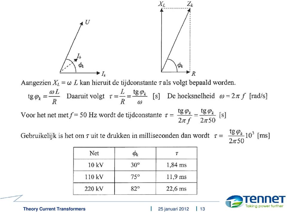
14 For a 220 kv line the Iksym is reached after: 22.6 * 5 = 113 msec. Theory Current Transformers 25 januari

15 Features of current transformers A primary winding (usually a cable or other conductors by toroidal). Set high primary currents to default value, usually 1 A or 5 A. Number of secondary windings in a CT with 1 A sec. current is equal to InP. For CT s with 5A secondary the number of turns is 1 / 5 x InP Maximum voltage for each winding is dependent on core material and diameter. Secondary is almost shorted and operated far from max tension / saturation. ti For Ru < Ru the Accuracy limiting factor (N ) is higher than the nominal(n). Internal winding resistance (Ri) is then important: t N = N x (Ri +R Ru) )/(Ri +R Ru ) Calculates the continuous 120% Ins. In short circuit conditions InP max lasts for upto 1or3s s. An open winding leads to a very hot and dangerous voltage (2500 / 1A, 5P650, 5 VA supplies ï»10 kv) and causes magnetic saturation. Winding insulation is only rated for a 2 kv peak voltage! Theory Current Transformers 25 januari
 is higher than the nominal(n).")
16 Specifying the nominal CT burden Typically used classes: 1 1,5 2 2, VA. The reted CT Burden should account for all the power consumption in the circuit(including the losses in the leads and the connected loads). For 1Acircuits 2VA CT Burden is usually sufficient. Resistance of the lines calculated with formula : (0, x l ) / A 0,0175 is the resistivity of copper (Ω. mm 2 / m) at 20 C. l = total length of all lines between CT terminals and consumers. (length of cables for return circuit it take 2x) A = surface cross section of conductor in mm2. For 1 A circuits the line losses (I 2 x R ) in VA are equal to the resistance. For 5 A circuits the line losses (I 2 x R ) in VA is equal to 25 times resistance. Theory Current Transformers 25 januari
 A = surface cross section of conductor in mm2.")
17 Accuracy Limit Factor N Typically used classes: P5 - P10 P15 P20 - P30 Factor (after the P) gives the current overload as a factor of nominal loading under rated current and 5% (5P) of 10% (10P) gives the accuracy limiting factor applicable at that overload of the CT. Limit Factor (N) calculated by multiplying the following factors: The Symmetric factor Kscc = Ikmax / Ipn. Thus a higher primairy nominal current (Ipn) limits the Kscc. Asymmetry factor Ktd depends on the net timeconstant. However, rapid protection, core type and smart digital relays limit KTD. Theory Current Transformers 25 januari
 limits the Kscc. Asymmetry factor Ktd depends on the net timeconstant.")
18 Theory Current Transformers 25 januari

19 CT Classes used in protection applications Type P,PX,TPX,TPS Type TPY,PR Type TPZ Closed core types, also known as high remenence Anti rememenance core, also known as low remenence Linear cores, also known as non remenence types Theory Current Transformers 25 januari

20 CT Behaviour during reclosing Theory Current Transformers 25 januari

21 CT dimensioning for Example differential protection (1) Theory Current Transformers 25 januari
22 CT dimensioning for Example differential protection (2) Theory Current Transformers 25 januari
23 CT dimensioning for Example differential protection (3) Theory Current Transformers 25 januari
24 CT dimensioning for Example differential protection (4) Theory Current Transformers 25 januari
25 Questions??? Theory Current Transformers 25 januari
Edmund Li. Where is defined as the mutual inductance between and and has the SI units of Henries (H).
.") INDUCTANCE MUTUAL INDUCTANCE If we consider two neighbouring closed loops and with bounding surfaces respectively then a current through will create a magnetic field which will link with as the flux passes
INDUCTANCE MUTUAL INDUCTANCE If we consider two neighbouring closed loops and with bounding surfaces respectively then a current through will create a magnetic field which will link with as the flux passes
Digital Energy ITI. Instrument Transformer Basic Technical Information and Application
 g Digital Energy ITI Instrument Transformer Basic Technical Information and Application Table of Contents DEFINITIONS AND FUNCTIONS CONSTRUCTION FEATURES MAGNETIC CIRCUITS RATING AND RATIO CURRENT TRANSFORMER
Chapter 16. Current Transformer Design. Copyright 2004 by Marcel Dekker, Inc. All Rights Reserved.
 Chapter 16 Current Transformer Design Table of Contents 1. Introduction 2. Analysis of the Input Current Component 3. Unique to a Current Transformer 4. Current Transformer Circuit Applications 5. Current
Application Note. So You Need to Measure Some Inductors?
 So You Need to Measure Some nductors? Take a look at the 1910 nductance Analyzer. Although specifically designed for production testing of inductors and coils, in addition to measuring inductance (L),
Chapter 14: Inductor design
 Chapter 14 Inductor Design 14.1 Filter inductor design constraints 14.2 A step-by-step design procedure 14.3 Multiple-winding magnetics design using the K g method 14.4 Examples 14.5 Summary of key points
DIMENSIONING OF CURRENT TRANSFORMERS FOR PROTECTON APPLICATION
 ÿþ üûúùø öõöôùóùõò CT Dimensioning DIMENSIONING OF CURRENT TRANSFORMERS FOR PROTECTON APPLICATION Application note GER3973 1 CT Dimensioning ÿþ üûúùø öõöôùóùõò GER-3973 Application note ÿþ üûúùø öõöôùóùõò
d di Flux (B) Current (H)
 Current (H)") Comparison of Inductance Calculation Techniques Tony Morcos Magnequench Technology Center Research Triangle Park, North Carolina 1 VCM Baseline: Geometry Axially-magnetized MQ3-F 42 NdFeB disk Br = 131kG
Comparison of Inductance Calculation Techniques Tony Morcos Magnequench Technology Center Research Triangle Park, North Carolina 1 VCM Baseline: Geometry Axially-magnetized MQ3-F 42 NdFeB disk Br = 131kG
Iron Powder Cores for Switchmode Power Supply Inductors. by: Jim Cox
 HOME APPLICATION NOTES Iron Powder Cores for Switchmode Power Supply Inductors by: Jim Cox Purpose: The purpose of this application note is to cover the properties of iron powder as a magnetic core material
Calculation of the Current Transformer Accuracy Limit Factor Application Note
 Calculation of the Current Transformer Application Note kansikuva_bw 1MRS 755481 Issued: 09.11.2004 Version: A/09.11.2004 Calculation of the Current Transformer Application Note Contents: 1. Scope...4
Chapter 11. Inductors ISU EE. C.Y. Lee
 Chapter 11 Inductors Objectives Describe the basic structure and characteristics of an inductor Discuss various types of inductors Analyze series inductors Analyze parallel inductors Analyze inductive
Theory of Heating by Induction
 CHAPTER 2 Theory of Heating by Induction INDUCTION HEATING was first noted when it was found that heat was produced in transformer and motor windings, as mentioned in the Chapter Heat Treating of Metal
Instrument Transformers Application Guide
 Instrument Transformers Application Guide Edited by ABB AB High Voltage Products Department: Marketing & Sales Text: Knut Sjövall, ABB Layout, 3D and images: Mats Findell, ABB SE-771 80 LUDVIKA, Sweden
Enhanced Quality with a Touch of Style
 Rudolf Current Transformer Enhanced Quality with a Touch of Style Current Transformer Enhanced Quality with a Touch of Style New Products Rudolf launched our new encapsulated current transformer. Portraying
CT Application Guide for the 489 Generator Management Relay
 g GE Power Management Technical Notes CT Application Guide for the 489 Generator Management Relay GE Publication No. GET-8402 Copyright 2002 GE Power Management Introduction A protection scheme operates
CURRENT TRANSFORMERS FOR ELECTRONIC WATTHOUR METERS ADVANCED MATERIALS THE KEY TO PROGRESS
 CURRENT TRANSFORMERS FOR ELECTRONIC WATTHOUR METERS ADVANCED MATERIALS THE KEY TO PROGRESS CURRENT TRANSFORMERS FOR ELECTRONIC WATTHOUR METERS VACUUMSCHMELZE GmbH & Co. KG (VAC) is one of the worldwide
Linear DC Motors. 15.1 Magnetic Flux. 15.1.1 Permanent Bar Magnets
 Linear DC Motors The purpose of this supplement is to present the basic material needed to understand the operation of simple DC motors. This is intended to be used as the reference material for the linear
Tape Wound, Split Core and Ebony Current Transformers
 Tape Wound, Split Core and Ebony Current Transformers Current Transformers Contents Page Tape Wound Measuring and Protection Current Transformers 2 6 Split Core Current Transformers 7 9 3-in-1 Current
OVERCURRENT & EARTH FAULT RELAYS. To study the protection of equipment and system by relays in conjunction with switchgear.
 OVERCURRENT & EARTH FAULT RELAYS Objective: To study the protection of equipment and system by relays in conjunction with switchgear. Theory: The function of a relay is to detect abnormal conditions in
CHAPTER 4 DESIGN OF INTEGRAL SLOT AND FRACTIONAL SLOT BRUSHLESS DC MOTOR
 47 CHAPTER 4 DESIGN OF INTEGRAL SLOT AND FRACTIONAL SLOT BRUSHLESS DC MOTOR 4.1 INTRODUCTION This chapter deals with the design of 24 slots 8 poles, 48 slots 16 poles and 60 slots 16 poles brushless dc
Equipment: Power Supply, DAI, Transformer (8341), Variable resistance (8311), Variable inductance (8321), Variable capacitance (8331)
, Variable resistance (8311), Variable inductance (8321), Variable capacitance (8331)") Lab 5: Single-phase transformer operations. Objective: to examine the design of single-phase transformers; to study the voltage and current ratios of transformers; to study the voltage regulation of the
Lab 5: Single-phase transformer operations. Objective: to examine the design of single-phase transformers; to study the voltage and current ratios of transformers; to study the voltage regulation of the
5. Measurement of a magnetic field
 H 5. Measurement of a magnetic field 5.1 Introduction Magnetic fields play an important role in physics and engineering. In this experiment, three different methods are examined for the measurement of
Chapter 7. Magnetism and Electromagnetism ISU EE. C.Y. Lee
 Chapter 7 Magnetism and Electromagnetism Objectives Explain the principles of the magnetic field Explain the principles of electromagnetism Describe the principle of operation for several types of electromagnetic
DIRECT CURRENT GENERATORS
 DIRECT CURRENT GENERATORS Revision 12:50 14 Nov 05 INTRODUCTION A generator is a machine that converts mechanical energy into electrical energy by using the principle of magnetic induction. This principle
Magnetic Circuits. Outline. Ampere s Law Revisited Review of Last Time: Magnetic Materials Magnetic Circuits Examples
 Magnetic Circuits Outline Ampere s Law Revisited Review of Last Time: Magnetic Materials Magnetic Circuits Examples 1 Electric Fields Magnetic Fields S ɛ o E da = ρdv B V = Q enclosed S da =0 GAUSS GAUSS
A METHOD OF CALIBRATING HELMHOLTZ COILS FOR THE MEASUREMENT OF PERMANENT MAGNETS
 A METHOD OF CALIBRATING HELMHOLTZ COILS FOR THE MEASUREMENT OF PERMANENT MAGNETS Joseph J. Stupak Jr, Oersted Technology Tualatin, Oregon (reprinted from IMCSD 24th Annual Proceedings 1995) ABSTRACT The
Direction of Induced Current
 Direction of Induced Current Bar magnet moves through coil Current induced in coil A S N v Reverse pole Induced current changes sign B N S v v Coil moves past fixed bar magnet Current induced in coil as
Current & Instrument Transformers
 Reliable & Accurate Inputs for Measuring & Protection Equipment Current & Instrument Transformers Type MKE11 Inside the Catalogue Range Specifications Ordering Code Delivering Value to You M-Kris Electric
WHITEPAPER CABLE CONDUCTOR SIZING
 WHITEPAPER CABLE CONDUCTOR SIZING FOR MINIMUM LIFE CYCLE COST Bruno De Wachter, Walter Hulshorst, Rodolfo di Stefano July 2011 ECI Available from www.leonardo-energy.org/node/156451 Document Issue Control
RM17TE 183...528 V AC. Main. Product or component type. Product specific application. Relay monitored parameters 250 V DC 5 A DC
 Characteristics multifunction control relay RM17-TE - range 183..528 V AC Complementary Reset time Maximum switching voltage Minimum switching current Maximum switching current [Us] rated supply voltage
Generator Stator Protection, under/over voltage, under /over frequency and unbalanced loading. Ramandeep Kaur Aujla S.NO 250447392
 1 Generator Stator Protection, under/over voltage, under /over frequency and unbalanced loading By Ramandeep Kaur Aujla S.NO 250447392 ES 586b: Theory and applications of protective relays Department of
EE301 Lesson 14 Reading: 10.1-10.4, 10.11-10.12, 11.1-11.4 and 11.11-11.13
 CAPACITORS AND INDUCTORS Learning Objectives EE301 Lesson 14 a. Define capacitance and state its symbol and unit of measurement. b. Predict the capacitance of a parallel plate capacitor. c. Analyze how
Last time : energy storage elements capacitor.
 Last time : energy storage elements capacitor. Charge on plates Energy stored in the form of electric field Passive sign convention Vlt Voltage drop across real capacitor can not change abruptly because
6 ELECTRICAL PARAMETERS
 6 ELECTRICAL PARAMETERS For power, low voltage and medium voltage cables, cross section nominal areas are calculated in taking into account several parameters as: permissible current carrying capacities
DESCRIPTION DWG DESCRIPTION DWG
 DESCRIPTION DWG DESCRIPTION DWG Ferroresonance 3451/1 3451/2 3451/3 Electro-magnetic Fields (EMF) 3462/1 HV & LV Insulators (Links) 3463/1 A ORIGINAL ISSUE B 14.07.09 APPROVED DATE J. Brooks 25.02.03 INDEX
Specifications for EM223 24 VDC 4 In/4 Out and EM223 24 VDC 4 In/4 Relay Out
 SIMATIC S7-200 EM223 Digital Combination Modules EM223 2 VDC In/ Out and EM223 2 VDC In/ Relay Out Table 1 Specifications for EM223 2 VDC In/ Out and EM223 2 VDC In/ Relay Out EM223 2VDC In/Out 6ES7 2231BF200XA0
Selecting IHLP Composite Inductors for Non-Isolated Converters Utilizing Vishay s Application Sheet
 VISHAY DALE www.vishay.com Magnetics Selecting IHLP Composite Inductors for Non-Isolated Converters INTRODUCTION This application note will provide information to assist in the specification of IHLP composite
Chapter 15: Transformer design
 Chapter 15 Transformer Design Some more advanced design issues, not considered in previous chapter: : n Inclusion of core loss + + Selection of operating flux i 1 density to optimize total loss v 1 v Multiple
1. The diagram below represents magnetic lines of force within a region of space.
 1. The diagram below represents magnetic lines of force within a region of space. 4. In which diagram below is the magnetic flux density at point P greatest? (1) (3) (2) (4) The magnetic field is strongest
Short Circuit Current Calculations
 Introduction Several sections of the National Electrical Code relate to proper overcurrent protection. Safe and reliable application of overcurrent protective devices based on these sections mandate that
Direction of current flow through conductor. Fig. 1 Magnetic field generated by current flow
 ingle Conductor Cable Copper heathed Cable heath Currents ingle conductor cables present certain application considerations that do not arise in multiconductor cable installations. These considerations
Bulletin 150 SMC Flex Smart Motor Controller Specifications
 Specifications Specifications Standard Features Optional Features Installation Setup Communications Power Wiring Control Wiring Keypad Software Starting and Stopping Modes Protection and Diagnostics Metering
Tape Wound, Split Core and Ebony Current Transformers
 Tape Wound, Split Core and Ebony Current Transformers Table of contents Tape Wound Measuring and Protection Current Transformers 2 MR Series Measuring Range 3 PR Series Protection Range 4 Class PX Current
0.84" x 2.00" Z-TRAUQ INC. Tel.: (450)226-6997 Fax: (450)226-5837 z-trauq@qc.aira.com SPLIT CORE CURRENT TRANSFORMER MODEL 1SP.
226-6997 Fax: (450)226-5837 z-trauq@qc.aira.com SPLIT CORE CURRENT TRANSFORMER MODEL 1SP.") SPLIT CORE CURRENT MODEL 1SP 0.84" x 2.00" PAGE No 3-2 REV 18DEC00 UL 1015 LEAD WIRE, STANDARD LENGTH IS 36 E DIMENSIONS A = 0.84 MIN B = 2.00 MIN C = 3.31 MAX D = 3.09 MAX E = 0.61 MAX F = 0 MAX F C B
SPLIT CORE CURRENT MODEL 1SP 0.84" x 2.00" PAGE No 3-2 REV 18DEC00 UL 1015 LEAD WIRE, STANDARD LENGTH IS 36 E DIMENSIONS A = 0.84 MIN B = 2.00 MIN C = 3.31 MAX D = 3.09 MAX E = 0.61 MAX F = 0 MAX F C B
2. A conductor of length 2m moves at 4m/s at 30 to a uniform magnetic field of 0.1T. Which one of the following gives the e.m.f. generated?
 Extra Questions - 2 1. A straight length of wire moves through a uniform magnetic field. The e.m.f. produced across the ends of the wire will be maximum if it moves: a) along the lines of magnetic flux
Chapter 10. AC Inductor Design. Copyright 2004 by Marcel Dekker, Inc. All Rights Reserved.
 Chapter 10 AC Inductor Design Table of Contents 1. Introduction 2. Requirements 3. Relationship of, A p, to the Inductor Volt-Amp Capability 4. Relationship of, K g, to the Inductor Volt-Amp Capability
SUBJECT: How to wire a motor starter Number: AN-MC-004 Date Issued: 2/08/2005 Revision: Original
 SUBJECT: How to wire a motor starter Number: AN-MC-004 Date Issued: 2/08/2005 Revision: Original A motor starter is a combination of devices to allow an induction motor to start, run and stop according
12. Transformers, Impedance Matching and Maximum Power Transfer
 1 1. Transformers, Impedance Matching and Maximum Power Transfer Introduction The transformer is a device that takes AC at one voltage and transforms it into another voltage either higher or lower than
DS 600. A contact free flux gate based current measurement sensor 600A rms
 DS 600 A contact free flux gate based current measurement sensor 600A rms DS 600 is member of the small housing sensor family. The family includes a 200A and a 600A version. 600A rms - 900A peak Maximum
48 SERIES Relay interface modules 10 A
 48 Relay interface modules 10 A 1 CO relay interface modules, mm wide Ideal interface for PLC and electronic systems Type 48.P3 1 CO 10 A s Type 48.31 1 CO 10 A s AC coils or DC sensitive coils Supply
PROPER SELECTION OF CONTROL CIRCUIT TRANSFORMERS WHITE PAPER BULLETIN 1497, 1497A, AND 1497B
 WHITE PAPER PROPER SELECTION OF CONTROL CIRCUIT TRANSFORMERS BULLETIN 1497, 1497A, AND 1497B CONTROL CIRCUIT TRANSFORMERS The proper selection of the control circuit transformers is important for suitable
Equipment: Power Supply, DAI, Wound rotor induction motor (8231), Electrodynamometer (8960), timing belt.
, Electrodynamometer (8960), timing belt.") Lab 13: Wound rotor induction motor. Objective: to examine the construction of a 3-phase wound rotor induction motor; to understand exciting current, synchronous speed and slip in this motor; to determine
Lab 13: Wound rotor induction motor. Objective: to examine the construction of a 3-phase wound rotor induction motor; to understand exciting current, synchronous speed and slip in this motor; to determine
Magnetic Field of a Circular Coil Lab 12
 HB 11-26-07 Magnetic Field of a Circular Coil Lab 12 1 Magnetic Field of a Circular Coil Lab 12 Equipment- coil apparatus, BK Precision 2120B oscilloscope, Fluke multimeter, Wavetek FG3C function generator,
Current Transformers Ratio / Polarity / Types
 CT1 Current Ratio / Polarity / Types Application Current (CT s) are instrument transformers that are used to supply a reduced value of current to meters, protective relays, and other instruments. CT s
Safety technique. Emergency stop module BO 5988 safemaster
 Safety technique Emergency stop module BO 5988 safemaster 0221562 Function diagram Pushbutton on Mains or emergencystop () K1 According to EC Directive for machines 98/37/EG According to IEC/E 60204-1
Transformer Calculations
 Transformer Calculations Transformers Transformers are one of the most basic yet practical devices used today. No matter where you are there is always a transformer nearby. They are used throughout alternating-current
Resistors. Some substances are insulators. A battery will not make detectible current flow through them.
 Resistors Some substances are insulators. A battery will not make detectible current flow through them. Many substances (lead, iron, graphite, etc.) will let current flow. For most substances that are
Mutual Inductance and Transformers F3 3. r L = ω o
 utual Inductance and Transformers F3 1 utual Inductance & Transformers If a current, i 1, flows in a coil or circuit then it produces a magnetic field. Some of the magnetic flux may link a second coil
7. Reactive energy compensation
 593 7. Reactive energy compensation 594 7. REACTIVE ENERGY COMPENSATION Reactive energy compensation is an important element for reducing the electricity bill and improving the quality of the electrical
Flux Conference 2012. High Efficiency Motor Design for Electric Vehicles
 Flux Conference 2012 High Efficiency Motor Design for Electric Vehicles L. Chen, J. Wang, P. Lombard, P. Lazari and V. Leconte University of Sheffield, Date CEDRAT : 18 October 2012 Presented by: P. Lazari
April 1. Physics 272. Spring 2014 http://www.phys.hawaii.edu/~philipvd/pvd_14_spring_272_uhm.html. Prof. Philip von Doetinchem philipvd@hawaii.
 Physics 272 April 1 Spring 2014 http://www.phys.hawaii.edu/~philipvd/pvd_14_spring_272_uhm.html Prof. Philip von Doetinchem philipvd@hawaii.edu Phys272 - Spring 14 - von Doetinchem - 164 Summary Gauss's
Coupled Inductors. Introducing Coupled Inductors
 Coupled Inductors From power distribution across large distances to radio transmissions, coupled inductors are used extensively in electrical applications. Their properties allow for increasing or decreasing
Introduction to Electricity & Magnetism. Dr Lisa Jardine-Wright Cavendish Laboratory
 Introduction to Electricity & Magnetism Dr Lisa Jardine-Wright Cavendish Laboratory Examples of uses of electricity Christmas lights Cars Electronic devices Human body Electricity? Electricity is the presence
The half cell of the storage ring SESAME looks like: Magnetic length =
 6. Magnets 6.1 Introduction SESAME will be perhaps erected in steps. The number of steps depends upon the available money. The cheapest way is to use the quadrupole and sextupoles from BESSY I. In this
Residual Current Circuit Breaker
 Introduction Residual Current Circuit Breaker / ELCB The Fault current overloads and short circuits can be detected by circuit breakers like MCB s MCCB s & HRC Fuses etc. But, Circuit breakers don t detect
Measurement of Capacitance
 Measurement of Capacitance Pre-Lab Questions Page Name: Class: Roster Number: Instructor:. A capacitor is used to store. 2. What is the SI unit for capacitance? 3. A capacitor basically consists of two
Presentation of the France Transfo factories
 Presentation of the France Transfo factories France Transfo's internationally recognised and highly esteemed expertise is today exported to more than 80 countries throughout the world. Over the past 15
Digital Pressure Measuring Instrument MDR480
 Description The digital panel instrument MDR480 is designed to measure, display, and monitor pressures in industrial applications. The instrument is panel mounted with a front frame dimension of 96 mm
CURRENT TRANSFORMER MODEL 546 UL1015 #16 AWG LEAD WIRE, STANDARD LENGTH IS 24" 1 X
 CURRENT TRANSFORMER MODEL 546 1.10" I.D. PAGE No 1-38 REV 15DEC00 TERMINAL OPTION LEAD WIRE OPTION 1.10 0 1.20 2.55 3.00 3.47 0.18 x 0.31 SLOT ( 2 PLACES) 8-32 BRASS STUD (2 PLACES) UL1015 #16 AWG LEAD
Meter Relays. 077 Series Analogue Meter Relays. Features. Applications
 077 Series Analogue Features Monitors and controls any variable which can be converted to an A.C. or D.C. signal. Rugged, shock and vibration resistant design Indicator, relays and power unit in one housing
Selecting the Optimal Inductor for Power Converter Applications
 Selecting the Optimal Inductor for Power Converter Applications BACKGROUND Today s electronic devices have become increasingly power hungry and are operating at higher switching frequencies, starving for
ElectroMagnetic Induction. AP Physics B
 ElectroMagnetic Induction AP Physics B What is E/M Induction? Electromagnetic Induction is the process of using magnetic fields to produce voltage, and in a complete circuit, a current. Michael Faraday
PTC-Resistor Temperature-Sensors MINIKA to DIN 44 081 and DIN 44 082
 PTC-Resistor Temperature-Sensors MINIKA to DIN 44 081 and DIN 44 082 General PTC-resistor temperature sensors (also called PTC-resistors or thermistors) are temperatur dependent semiconductor resistors
Brush DC Motor Basics. by Simon Pata Business Unit Manager, Brushless DC
 thinkmotion Brush DC Motor Basics by Simon Pata Business Unit Manager, Brushless DC Ironless DC Motor Basics Technical Note Brushed DC ironless motors are found in a large variety of products and applications
Transformer circuit calculations
 Transformer circuit calculations This worksheet and all related files are licensed under the Creative Commons Attribution License, version 1.0. To view a copy of this license, visit http://creativecommons.org/licenses/by/1.0/,
ABSTRACT 1. INTRODUCTION
 Inductor Cores Material and Shape Choices by Mark A. Swihart, Manager of Applications Engineering Magnetics, Division of Spang & Co. Pittsburgh, Pennsylvania USA ABSTRACT A carefully considered power inductor
FLEXIBLE INDUSTRIAL CABLES H07RN-F TENAFLEX SR
 FLEXIBLE INDUSTRIAL CABLES H07RN-F TENAFLEX SR Standards : CENELEC HD 22.4 NF C 32-102-4 DIN VDE 0282-1 and VDE 0282-4 BS 6007 and BS 6500 IEC 60245-4 Rated voltage Rated voltage: 450/750 V (Use up to
Homework #11 203-1-1721 Physics 2 for Students of Mechanical Engineering
 Homework #11 203-1-1721 Physics 2 for Students of Mechanical Engineering 2. A circular coil has a 10.3 cm radius and consists of 34 closely wound turns of wire. An externally produced magnetic field of
Thermistor motor protection
 Thermistor motor protection CM-E Range Thermistor motor protection Thermistor motor protection relays Benefits and advantages Selection table Operating principle and fields of application for thermistor
KOLMA and IHDA Indoor type Cable Current Transformers Catalogue ABB Power Distribution ABB Transmit 1 KKOLMA 1 GB
 KOLMA and IHDA Indoor type Cable Current Transformers Catalogue ABB Power Distribution ABB Transmit 1 KKOLMA 1 GB KOLMA and IHDA Indoor Type Cable Current Transformers Index Description... 3 Technical
40 Series - Miniature PCB/Plug-in relays 8-10 - 16 A. Features 40.31 40.51 40.52
 Features 40.31 40.51 40.52 1 & 2 Pole relay range 40.31-1 Pole 10 A (3.5 mm pin pitch) 40.51-1 Pole 10 A (5 mm pin pitch) 40.52-2 Pole 8 A (5 mm pin pitch) PCB mount - direct or via PCB socket 35 mm rail
The Importance of the X/R Ratio in Low-Voltage Short Circuit Studies
 The Importance of the X/R Ratio in Low-Voltage Short Circuit Studies DATE: November 17, 1999 REVISION: AUTHOR: John Merrell Introduction In some short circuit studies, the X/R ratio is ignored when comparing
LOW-VOLTAGE CURRENT TRANSFORMERS
 LOWVOLTAGE CURRENT TRANSFORMERS 5 A Power network meters ND0 and ND type. N4Z and N5Z Tel: (+48 68) 45 75 39; 45 75 305; 45 75 3; 45 75 368; email: export@lumel.com.pl ul. Słubicka 657 Zielona Góra CONTENTS
Guide to the electrical parameter classifications of IEC 60950 and IEC 62368 safety standards
 Guide to the electrical parameter classifications of IEC 60950 and IEC 62368 safety standards Abstract This Guide is an informative listing of selected terms and definitions found in IEC Glossary entry
Current valve. for AC 24 V pulse/pause control of electrical loads up to 30 kw
 4 937 DESIO Current valve for AC 24 V pulse/pause control of electrical loads up to 30 kw SEA45.1 Use The current valve is used for the control of electric heating elements in heating, ventilation and
Ammeter / Voltmeter Series 8402, 8403, 8405, 8404
 /, 8403, 8405, 8404 > Fast comparison of measured with set values > s available, 8403 and 8402 www.stahl.de, 8403, 8405, 8404 10073E00 The ammeters and voltmeters from R. STAHL are explosion protected,
USER MANUAL THE RESOLVER
 USR MANUAL TH RSOLVR ICP Department 4 has developed and produced a wide range of transmitter type resolvers for military and industrial applications. From a mechanical viewpoint, these products have been
HPS Universal. Single and Three Phase Potted. Buck-Boost Transformers. Buck-Boost Applications & Standard Specification... 80
 Buck-Boost Transformers Single and Three Phase Potted Buck-Boost Transformers Buck-Boost Applications & Standard Specification... 80 Selecting Buck-Boost Transformers... 81 Single Phase Selection Tables...
Current Probes. User Manual
 Current Probes User Manual ETS-Lindgren L.P. reserves the right to make changes to any product described herein in order to improve function, design, or for any other reason. Nothing contained herein shall
For the electronic measurement of current: DC, AC, pulsed..., with galvanic separation between the primary and the secondary circuit.
 Current Transducer HO-P series I PN = 6, 10, 25 A Ref: HO 6-P, HO 10-P, HO 25-P For the electronic measurement of current: DC, AC, pulsed..., with galvanic separation between the primary and the secondary
How to Optimize Performance and Minimize Size in High Speed Applications High Performance Brushless DC Motors
 thinkmotion How to Optimize Performance and Minimize Size in High Speed Applications High Performance Brushless DC Motors I. Introduction II. III. IV. Optimization of a Brushless DC motor for high speed
Tamura Closed Loop Hall Effect Current Sensors
 Tamura Closed Loop Hall Effect Current Sensors AC, DC, & Complex Currents Galvanic Isolation Fast Response Wide Frequency Bandwidth Quality & Reliability RoHs Compliance Closed Loop Hall Effect Sensors
45. The peak value of an alternating current in a 1500-W device is 5.4 A. What is the rms voltage across?
 PHYS Practice Problems hapters 8- hapter 8. 45. The peak value of an alternating current in a 5-W device is 5.4 A. What is the rms voltage across? The power and current can be used to find the peak voltage,
Earth Fault Detection Basics in Theory
 Earth Fault Detection Basics in Theory Author: Dipl.-Ing. Ingo Kühnen Woodward Power Solutions Krefelder Weg 47 47906 Kempen, Germany Kempen, 16.04.2010 Earth_Fault_Detection_20100416.doc page 1 1. Star
Prepared By: Sheilani Binti Shaari Department of Electrical Engineering/PKB
 Prepared By: Sheilani Binti Shaari Department of Electrical Engineering/ Course Learning Outcome (CLO) Upon completion of this course, students should be able to: Apply the principles of three phase systems,
Lab 14: 3-phase alternator.
 Lab 14: 3-phase alternator. Objective: to obtain the no-load saturation curve of the alternator; to determine the voltage regulation characteristic of the alternator with resistive, capacitive, and inductive
Magnetic Field Evaluation in Transformers and Inductors
 Magnetic Field Evaluation in Transformers and Inductors By Lloyd H. Dixon This topic reveals, by means of magnetic field plots, many of the problems that occur in magnetic device structures, utilizing
Using Current Transformers with the 78M661x
 A Maxim Integrated Products Brand Using Current Transformers with the 78M661x APPLICATION NOTE AN_661x_021 April 2010 Introduction This application note describes using current transformers (CT) with the
Improved PFC Boost Choke using a Quasi-Planar Winding Configuration Dave Shonts Schott Corporation 1000 Parkers Lake Road Wayzata, MN 55391
 Improved PFC Boost Choke using a Quasi-Planar Winding Configuration Dave Shonts Schott Corporation 1000 Parkers Lake Road Wayzata, MN 55391 Abstract- A novel approach to boost inductor design using a quasi-planar
VOLTAGE REGULATOR AND PARALLEL OPERATION
 VOLTAGE REGULATOR AND PARALLEL OPERATION Generator sets are operated in parallel to improve fuel economy and reliability of the power supply. Economy is improved with multiple paralleled generators by
EARTHING SYSTEM CALCULATION
 BAZIAN STEAL FACTORY S/S 132/11kV, 1x30/40MVA EARTHING SYSTEM CALCULATION Kurdistan Region Sulaimani May 2011 Bazian Steal Factory S/S 132/11kV, 1x30/40 MVA Contents: 1. Introduction... 3 2. List of references