We ve Bent The Rules. AR s Bent-Element Approach Provides A Size Reduction Of Up To 75%, Along With Great Performance.
|
|
|
- Randolf Lyons
- 7 years ago
- Views:
Transcription
1 Antennas 76
2 We ve Bent The Rules. AR s Bent-Element Approach Provides A Size Reduction Of Up To 75%, Along With Great Performance. AR is doing incredible things with antennas. For starters, we ve advanced the science of log-periodic antennas with our patented Radiant Arrow design. Our Radiant Arrow bent element antennas for fields from 26 MHz to 6,000 MHz are about % smaller, lighter and more compact than standard log-periodic antennas. Yet they cover broad frequency ranges, offer up to 6dBi gain, and produce high fields even in the toughest applications. The smaller size not only makes them more portable, it minimizes field loss from room loading. Our newest Radiant Arrow antenna pushes the boundaries even farther. The ATR26MG (26 0 MHz /,000 watts input power) goes beyond existing susceptibility requirements, so it s ready for future developments. And the robust design accommodates the high power levels needed to generate significant E-fields. AR is also THE source for microwave and RF horn antennas, broadband log-periodics, and antennas for HIRF testing. Antennas are available up to GHz and,000 watts of input power. All AR antennas develop high fields, suitable for RF and EMC testing, and many models can be calibrated for emissions testing. All our antennas are frequency and power-matched to AR amplifiers, so it s easy to select the right unit. 77

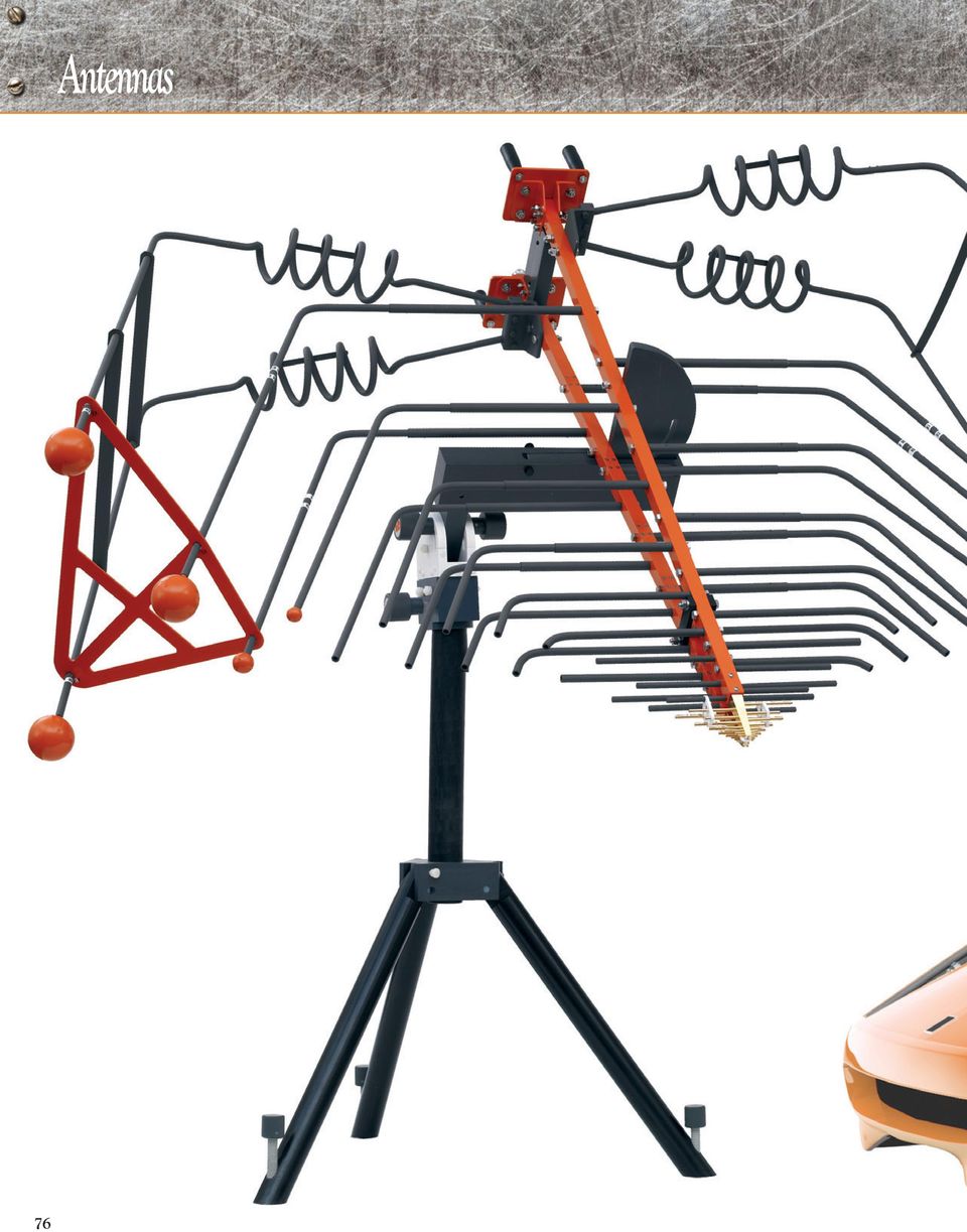
3 Antennas Radiant Arrow Antennas That Take Technology To New Heights Quick Change Connectors Most antennas come with quick change connectors so you can easily change to accommodate various cabling and amplifier outputs. 78 Model ATR26M6G- shown on model TP0B tripod.

4 AR has advanced the science of log-periodic antennas with the unique, patented design of our Radiant Arrow bent element antennas - for fields from 26 MHz to 6 GHz. This exceptional family of antennas includes the ATRM6G ( MHz - 6 GHz, 5,000 watts input power), the ATR26M6G and ATR26M6G- (26 MHz - 6 GHz, 5,000 watts input power) and the ATR26M2 (26 MHz - 2 MHz, 5K watts input power). The Radiant Arrows utilize a bent-element approach that provides a size reduction up to 75% without sacrificing key electrical performance such as gain or bandwidth. The size reduction minimizes field loss resulting from room loading - which is especially troublesome when conventional logperiodic antennas are used in small enclosures. All four models feature a vertical to horizontal pivot to allow bore sight rotation without removing an element from the antenna or removing the antenna from the AR positioner. Remove a pin and easily rotate the antenna to the desired position. 79

5 Antennas Radiant Arrow Antenna ATR26MG 26 MHz to 0 MHz The Model ATR26MG is a wideband, high gain, log periodic antenna that is uniquely suited for use in both traditional applications as well as in new compact chambers. The proprietary design, utilizing a bent element approach combined with additional innovations, provides a size reduction of approximately 75% without sacrificing key electrical performance such as gain and beamwidth. The reduced profile and extremely low VSWR make it an excellent choice for high field-strength immunity testing, and the robust design can accommodate the high power levels necessary to generate significant E-fields. The ATR26MG can also be calibrated for RF emissions testing. This antenna is built tough enough for outdoor use and can be mounted using the base plate or in two perpendicular planes with the APB antenna positioner. Can be custom calibrated to the user s requirement for use in RF emission testing. The calibrated model is designated by adding a CC suffix to the desired model version. Calibration details must be provided using Form 70. Contact factory for details. ATR26MG MEASURED AT METER Specifications Frequency range ATR26MG 26 0 MHz kw * 0 V/m kw * Power input, CW Power gain (over isotropic) Gain flatness Impedance 26 MHz, derate to 5 0 MHz - 8 to 0 db (26 MHz) 0 6 db ( 0 MHz) ±3 db ( 0 MHz) ohms nominal 0 Watts Watts Watts Watts 25 Watts Watts 5kW 2.5kW kw V/m VSWR (max.) Beamwidth (average) Connector Size (W X H X D) Weight (max.) 6: (26 MHz) 3: ( 0 MHz) Typical curves available on request 5/8 EIA m/f 23 x 66 x 83 cm (9 x 26 x 72 in) 29.5 kg (65 lb) V/m 0 * Input power above 5kW limited by frequency MEASURED AT 3 METERS 0 V/m Mounting May be mounted in two perpendicular planes using an optional antenna positioner (APB). One non-metallic mast (4 foot) is included for vertical mounting. 0 Watts Watts Watts Watts 25 Watts kw * kw * 5kW 2.5kW V/m kw Watt V/m 0 * Input power above 5kW limited by frequency

6 ATR26M6G- 26 MHz to 6 GHz The new Model ATR26M6G- is uniquely suited for use in both traditional applications and in compact test chambers. Its exceptionally broad frequency range addresses existing RF susceptibility requirements as well as anticipated developments. The ATR26M6G- features a 75% size reduction over standard log periodic antennas covering this frequency range. It is matched to work directly with AR s W, S and A series RF power amplifiers. The robust design can accommodate the high power levels necessary to generate significant E-fields. The ATR26M6G- can also be calibrated for RF emissions testing. The antenna can be supported with the APB antenna positioner, or the TP0BM3 with ballast tray. Can be custom calibrated to the user s requirement for use in RF emission testing. The calibrated model is designated by adding a CC suffix to the desired model version. Calibration details must be provided using Form 70. Contact factory for details. ATR26M6G- MEASURED AT METER Specifications Frequency range Power input (max.) Power gain (over isotropic) Gain flatness Impedance ATR26M6G- 26 MHz - 6 GHz 00 watts - 4 to 6 db (26 MHz) 6 db ( MHz 6 GHz) ±.5 db ( MHz 6 GHz) ohms nominal Watts Watts Watts Watts Watts 0 0 Watts 0 0 Watts 2 2 Watts Watts VSWR (max.) 6: (26 MHz) 3: ( MHz 6 GHz) 5 Watts Watts Beamwidth (average) Front to back ratio (min.) Connector Size (W X H X D) Weight (max.) Typical curves available on request 5 db Type N (F) quick change connector; Type C (F) supplied for higher power applications 28.4 x 73.7 x 6.3 cm (86 x 29 x 63.5 in) 3.6 kg ( lb) Watt Watt MEASURED AT 3 METERS 0 0 Mounting May also be mounted using the optional APB antenna positioner or the TP0BM3 tripod with ballast tray. Also includes 2 non-metallic masts (4 and 6 feet) vertical mounting. 0 0 Watts 2 2 Watts Watts Watts Watts Watts Watts Watts Watts 0 0 Watts Watts Field strengths have been measured in free-space conditions. Individual shielded rooms, amplifiers, and test-system conditions will influence performance. Field strength also varies with frequency and position of antenna and EUT in non-anechoic testing environments. Watt Watt

7 Antennas The Most Advanced Antennas For Radiated EMC Testing a: ATR26M2-26 to 2 MHz b: ATR26M6G - 26 MHz to 6 GHz c: ATRM6G - MHz to 6 GHz d: ATRM6G - MHz to 6 GHz Our Radiant Arrows offer up to 6dBi gain and produce high fields even in the toughest applications. They can also be calibrated for emissions testing. These efficient, compact, portable antennas represent the innovative thinking and exceptional products that have earned AR the Number One position in the industry. a: Shown on model APB b: Antenna Mounting Adapters Available for older versions of the AT0, AT and AT antennas. Allows for vertical & horizontal polarization changes without removing the antenna from the tripod. Can be custom calibrated to the user s requirement for use in RF emission testing. The calibrated model is designated by adding a CC suffix to the desired model version. Calibration details must be provided using Form 70. Contact factory for details. Specifications ATR26M2 ATR26M6G ATRM6G ATRM6G Frequency range 26-2 MHz 26 MHz - 6 GHz MHz - 6 GHz MHz - 6 GHz Power input (max.)* 5,000 watts 5,000 watts 5,000 watts 5,000 watts Power gain (over isotropic) - 3 to +6 dbi (26 - MHz) - 3 to +6 dbi (26 - MHz) 6 dbi 6 dbi 6 dbi ( - 2 MHz) 6 dbi ( MHz - 6 GHz) Gain flatness ±.5 dbi ( - 2 MHz) ±.5 dbi ( - 6 GHz) ±.5 dbi ±.5 dbi Impedance ohms nominal ohms nominal ohms nominal VSWR (max.) 3: ( - 2 MHz) 3: ( - 6 GHz) 3: 3: : (26 - MHz) : (26 - MHz) 2: (typical) 2: (typical) Beamwidth (avg.) Typical curves available Typical curves available Typical curves available Typical curves available on request on request on request on request Connector 5/8 EIA Type N (F) Type N (F) quick change connector quick change connector quick change connector Size (W X H X D) x 53.6 x 2.4 cm x 53.6 x 2.4 cm 32. x.32 x 97.8 cm 82.6 x 7.8 x 57.2 cm ( x 2. x 79.7 in) ( x 2. x 79.7 in) (52 x 8 x 38.5 in) (32.5 x 7 x 22.5 in) Weight (max.) 3.8 kg (70 lb) 22.7 kg ( lb) 7.94 kg (7.5 lb) 5 kg (2 lb) Mounting May be mounted in two May be mounted in two May be tripod mounted in May be tripod mounted in perpendicular planes using perpendicular planes using two perpendicular planes two perpendicular planes an optional antenna positioner an optional antenna positioner using optional tripod. Also using optional tripod. Also (APB). One non-metallic (APB). Two non-metallic includes one non-metallic includes one non-metallic mast (4 foot) is included for masts (4 and 6 foot) are mast for vertical mounting. mast for vertical mounting. vertical mounting included for vertical mounting Shown on model APB c: Shown on model TP0B d: *Connector and frequency dependent. Contact factory for details. Typical gain charts and antenna patterns are available for most antennas. Contact factory for more information. Shown on model TP0B 82

8 ATR26M2 FIELD STRENGTH (V/m) (V/m) ATR26M2 MEASURED AT METER ATR26M2 MEASURED AT METER kW kw 0 0W 5kW kw 2W 2.5kW 5kW 0W W 2W 2.5kW kw W W W kw W 25W W W 25W W ATR26M6G ATR26M6G MEASURED AT METER 00 WATTS 0 WATTS 0 WATTS WATTS WATTS ATR26M2 MEASURED AT 3 METERS ATR26M6G MEASURED AT 3 METERS ATR26M2 MEASURED AT 3 METERS FIELD STRENGTH (V/m) (V/m) 0W 0W 2W W 2W W W W W 25W W 25W W W 5kW kw 5kW kw 5kW 2.5kW 5kW 2.5kW kw kw WATTS 00 WATTS 0 WATTS 0 WATTS WATTS ATRM6G ATRM6G MEASURED AT METER 0 00 WATTS 0 WATTS 0 WATTS WATTS WATTS ATRM6G MEASURED AT 3 METERS 0 ATRM6G (V/m) 0 00 ATRM6G MEASURED AT METER 0 WATTS WATTS WATTS ATRM6G MEASURED AT METER 0 00 WATTS 0 WATTS 0 0 WATTS WATTS WATTS ATRM6G MEASURED AT 3 METERS 0 (V/m) 00 WATTS 0 WATTS 0 WATTS WATTS WATTS Field strengths have been measured in free-space conditions. Individual shielded rooms, amplifiers and test systems conditions will influence performance. Field strength also varies with frequency and position of the antenna and EUT in non-anechoic testing environments (V/m) ATRM6G MEASURED AT 3 METERS 0 00 WATTS 0 WATTS 0 WATTS 00 WATTS WATTS 0 WATTS 0 WATTS WATTS WATTS WATTS (V/m) 83
 0 00 ATRM6G")
9 Antennas Broadband Log-periodic. High Gain. Wide Band. Excellent Performance. a: ATLMG b: ATLMG c: ATS700MG MHz to.5 GHz To 0 V/m You can count on AR s high gain log-periodics to deliver the constant high intensity fields you need for RFI and EMI testing, in and out of a shielded room. You ll also get frequency response and field intensity that goes beyond the norm. Their lightweight, compact design makes relocation easy and they can easily be mounted on a flat surface or tripod. And these antennas are built tough to stand up to the outdoors. These antennas have been designed to allow polarization change without removing the antenna from a tripod, and can be calibrated for emissions testing. The newest addition to our family of high gain, log-periodic antennas, model ATS700MG is a stacked, log-periodic which provides a minimum gain of 6.5dB over isotropic and covers the 700 MHz.5 GHz frequency range. Its excellent field uniformity and greater than 9dBi gain over -6 GHz make it ideal for the IEC--4-3 standard. It is supplied with full calibration data, and can also perform emissions measurements. Can be custom calibrated to the user s requirement for use in RF emission testing. The calibrated model is designated by adding a CC suffix to the desired model version. Calibration details must be provided using Form 70. Contact factory for details. Specifications ATLMG ATLMG ATS700MG Frequency range -,000 MHz -,000 MHz 700 MHz -.5 GHz Power input (max.) 2,000 watts 2,000 watts 0 watts Power gain (over isotropic) 6.5 dbi min., 6.5 dbi min., 7 dbi min., 7.5 dbi avg. 7.5 dbi avg. 9.8 dbi avg. Gain flatness ±.0 dbi ±.0 dbi ±.0 dbi Impedance ohms nominal ohms nominal ohms nominal VSWR.8: (max.).8: (max.) <.5: (to 7 GHz).5: (average).5: (average) 2.8: (7 GHz to.5 GHz) Beamwidth (average) E plane E plane E plane 46 H plane 5 H plane 5 H plane 48 Front to back ratio (min.) 5 db 5 db 5 db Connector Type N (F) Type N (F) Type N precision quick change connector; quick change connector; Type C (F) supplied for Type C (F) supplied for higher power applications higher power applications Size (W X H X D) 93 x 3 x cm 2 x 3 x 9 cm 46 x 27 x 27 cm (76 x 5. x 63 in) ( x 5. x 36 in) (8 x.6 x.6 in) Weight (max.) 7 kg (5 lb) 7 kg (5 lb) 3.7 kg (8.4 lbs) Mounting May be mounted May be mounted May be tripod mounted using the optional using the optional with included tripod mount. TP0B tripod. TP0B tripod. a: Shown on model TP0B ATLMG MEASURED AT METER WATTS 00 WATTS 0 WATTS 0 WATTS WATTS Note: Curves above 0 and 0 watts do not apply past power-frequency limits of the antenna. MEASURED AT 3 METERS WATTS 00 WATTS 0 WATTS 0 WATTS WATTS

10 b: c: Shown on model TP0B ATLMG WATTS MEASURED AT METER 00 WATTS 0 WATTS 0 WATTS WATTS Note: Curves above 0 and 0 watts do not apply past power-frequency limits of the antenna. MEASURED AT 3 METERS WATTS 00 WATTS 0 WATTS 0 WATTS WATTS FIELD STRENGTH (V/m) (V/m) FIELD STRENGTH (V/m) (V/m) 0 MEASURED AT METER 0 Watts Watts Watts Watts Watts Watts Watts Watts 5 Watts 5 2 Watts Watts 2 Watts Watt Watt MEASURED AT 3 METER MEASURED AT 3 METER Watts Watts Watts Watts Watts Watts Watts Watts 5 Watts 5 Watts 2 Watts 2 Watts Watt Watt ATS700MG MEASURED AT METER Field strengths have been measured in free-space conditions. Individual shielded rooms, amplifiers, and test-system conditions will influence performance. Field strength also varies with frequency and position of antenna and EUT in non-anechoic testing environments

11 Antennas RF Horns. High Gain Over A Broad Spectrum. a: ATHMG b: ATHMG- c: ATH0MG To,000 MHz To 0 V/m Our RF horn antennas exhibit increasing gain with frequency up to 8 dbi at,000 MHz, helping to compensate for losses that occur elsewhere in an RF test system. The ATHMG handles up to 5,000 watts input power and can be used with AR s high power amplifiers. You can use these antennas in shielded rooms for free space testing. Can be custom calibrated to the user s requirement for use in RF emission testing. The calibrated model is designated by adding a CC suffix to the desired model version. Calibration details must be provided using Form 70. Contact factory for details. ATHMG a: Shown on model TP00 MEASURED AT METER WATTS MEASURED AT 3 METERS 00 WATTS 0 WATTS 0 WATTS WATTS WATTS 0 WATTS 0 0 WATTS WATTS 8 WATTS Specifications ATHMG ATHMG- ATH0MG Frequency range -,000 MHz -,000 MHz 0 -,000 MHz Power input (max.) 5,000 watts,000 watts See graph Power gain (over isotropic) dbi min., dbi min., dbi min., typically increasing to typically increasing to typically increasing to 8 dbi at,000 MHz 8 dbi at,000 MHz 5 dbi at,000 MHz Impedance ohms nominal ohms nominal ohms nominal VSWR 2.5: max.,.5: avg. 2.5: max.,.5: avg. 2.5: max.,.5: avg. Beamwidth (front to back) Typical curves Typical curves See curve available on request available on request Connector Type - 5/8 EIA Flange, Type - 5/8 EIA Flange Quick Change block. Quick Change See Model Configurations. Connector Mounting Heavy-duty tripod included. Pads with 3/8-6 thread Rear flange for wall mount. Pads with 3/8-6 thread for stand mounting Pads with /4- thread for stand mounting vertically or horizontally. for tripod mount. vertically or horizontally. Weight 46 kg ( lb) 46 kg ( lb) 9. kg ( lb) Size (W X H X D) 9.2 x 45.8 x 75.3 cm 9.2 x 45.8 x 75.3 cm 56.4 x 79.3 x 73.7 cm (43 x 57 x 69 in) (43 x 57 x 69 in) (22.2 x 3.2 x 29 in) Field strengths have been measured in free-space conditions. Individual shielded rooms, amplifiers, and test-system conditions will influence performance. Field strength also varies with frequency and position of antenna and EUT in non-anechoic testing environments. 86

12 b: c: Shown on model TP0B ATHMG- MEASURED AT METER ATH0MG MEASURED AT METER WATTS WATTS,000 WATTS 00 WATTS 0 WATTS 0 WATTS WATTS WATTS WATTS 00 WATTS 0 WATTS 0 WATTS WATTS MEASURED AT 3 METER MEASURED AT 3 METERS WATTS WATTS,000 WATTS 00 WATTS 0 WATTS 0 WATTS WATTS WATTS WATTS 0 WATTS 0 WATTS WATTS

13 Antennas Suite of Antennas for DO HIRF Testing a: 88 b: c: Shown on model TP0B

14 a: ATH2G4-2 to 4 GHz b: ATH4G6-4 to 6 GHz c: ATH6G8-6 to 8 GHz A Special Family of Antennas for High Intensity Radiated Field (HIRF) Testing High fields - whether from radar or other electronic devices, or generated by enemy/terrorist forces - can cause electronic equipment to malfunction, stop working, or worse. Our amplifiers and antennas are critical components in generating high intensity fields for testing electronic equipment. To keep up with the demands of HIRF testing, AR has developed a new family of antennas with the power and bandwidth needed for high field testing. These are all high-gain, high-power microwave horn antennas that provide typical dbi over isotropic. They supply high intensity fields for DO HIRF testing. They are extremely compact and lightweight for easy mobility. Yet they re built tough to withstand the demands of outdoor use. All three antennas are designed to mount easily on a tripod or to a mounting plate; and can be used with AR s power-pulsed traveling wave tube amplifiers. Can be custom calibrated to the user s requirement for use in RF emission testing. The calibrated model is designated by adding a CC suffix to the desired model version. Calibration details must be provided using Form 70. Contact factory for details. Specifications ATH2G4 ATH4G6 ATH6G8 Frequency range 2-4 GHz 4-6 GHz 6-8 GHz Power input (max.),000 watts CW 0 watts CW 700 watts CW6 7.5 GHz 0 watts CW7.5 8 GHz Peak Pulse less than % 7 kw Peak Pulse 5 kw Peak Pulse kw Peak Pulse (% duty cycle 6μs (% duty cycle 6μs (% duty cycle 6μs pulse width) pulse width) pulse width) Power gain (over isotropic) 7 dbi min. 8 dbi typ. 8 dbi typ. VSWR Max..5:.5:.5: Average.3:.3:.3: Beamwidth (avg.) E Plane H Plane Connector 7 6 DIN connector 7 6 DIN connector 7 6 DIN connector Weight.36 kg (25 lb).59 kg (3.5 lb) 9 kg (2 lb) Size (WxDxH) x 29.4 x 98. cm 23. x 7.0 x cm 6.25 x 2.06 x cm (9 x 2 x.2 in) (9. x 6.7 x 8.5 in) (6.4 x 4.75 x 5.5 in) Mounting Mounting pad on the Mounting pad on the Mounting pad on the E-plane and H-plane E-plane and H-plane E-plane and H-plane for tripod for tripod for tripod 0 Watts Watts Watts Watts 25 Watts Watts ATH2G4 MEASURED AT METER Watts Watts Watts Watts Watts 5 Watts Watts Watts Watts Watts Watts 5 Watts ATH4G6 MEASURED AT METER ATH6G8 MEASURED AT METER 5kW Pulse kw Pulse 5kW Pulse 2.5kW Pulse 0W kw kw Pulse 5kW Pulse 2kW Pulse kw Pulse kw Pulse 5kW Pulse 2kW Pulse kw Pulse 0W Field strengths have been measured in free-space conditions. Individual shielded rooms, amplifiers, and test-system conditions will influence performance. Field strength also varies with frequency and position of antenna and EUT in non-anechoic testing environments. 89

15 Antennas Compact, Lightweight Microwave Horns To GHz Field strengths have been measured in free-space conditions. Individual shielded rooms, amplifiers, and test-system conditions will influence performance. Field strength also varies with frequency and position of antenna and EUT in nonanechoic testing environments. a: e: d: b: c: Even our microwave horns provide exceptional performance. Along with our broadband RF antennas, our microwave horns are specially designed to compensate for the losses that typically occur in test systems as frequency increases. These innovative microwave horn antennas are compact and lightweight for easy mobility, yet they re tough enough for the extra demands of outdoor use, and they easily mount on a tripod. Several of our microwave horns have removable gain enhancers that improve the field strength to perform 3-meter testing. a: ATH4G8 b: ATH7G8 c: ATH8G27 d: ATH8G27- e: ATH26G Specifications ATH0M5GA ATH0M6G ATH2G8 ATH2G ATH2G8A ATH4G8 Frequency range 0 MHz - 5 GHz 0 MHz - 6 GHz 2 GHz - 8 GHz 2 - GHz GHz 4-8 GHz Power input (max.),0 watts 2,0 watts watts 700 watts 2kW 0 watts Peak power input (max.) 5 kw peak pulse 5 kw peak pulse (% duty cycle 6μs (% duty cycle 6μs pulse width) pulse width) Power gain (over isotropic) dbi min, dbi min, 6 dbi min, 2.5 dbi min., 9.5 dbi min,.5 dbi min., increasing to 2 dbi increasing to 24 dbi increasing to 2 dbi increasing to increasing to 8 dbi increasing to at 5 GHz at 6 GHz at 8 GHz 23 dbi at GHz at 7.5 GHz. 5.9 dbi at 8 GHz 7.8 dbi min., increasing to 2.2 dbi at 8 GHz with gain enhancer Impedance ohms nominal ohms nominal ohms nominal ohms nominal ohms nominal ohms nominal VSWR Max. 2.5: 2.5: 3.0: 2:.8:.6: Average.6:.6: 2.0:.5:.3:.3: Beamwidth (avg.) at 3dBi down from peak E Plane with gain enhancer H Plane with gain enhancer Connector 7-6 DIN (F), Type N(F) 7-6 DIN (F) SMA (F) N (F) WRD-2-D N (F) Quick change connector Quick change connector Weight 7.26 kg (6 lb) 7.26 kg (6 lb) 283.5g ( oz.).59 kg (3.5 lb).8 kg (2.5 lb) 2.27 kg (5 lb) Size (WxDxH) 46.3 x 46.3 x 69.2 cm 46.3 x 46.3 x 69.2 cm 2.64 x 8.23 x 9.85 cm 22.9 x 7.8 x 3.75 cm 2.2 x 9.9 x.3 cm without gain enhancer (8.25 x 8.25 x in) (8.25 x 8.25 x in) (4.98 x 3.24 x 3.88 in) (9 x 7 x 2.5 in) (4.8 x 3.9 x 8 in) 7.62 x.3 x 5.4 cm 3.00 x 4.06 x 5.96 in with gain enhancer: 2.6 x 2.6 x.5 cm (8.5 x 8.5 x 2 in) 90

16 Specifications ATHM2G ATHG8 Frequency range MHz - 2 GHz -8 GHz Power input (max.),000 watts 0 watts up to 7 GHz; above 7 GHz, derate linearly to 75 watts at 8 GHz Power gain (over isotropic) 6 dbi typ. 6 dbi min. Impedance ohms nominal ohms nominal VSWR (typ.) 2: 2: Beamwidth (avg.) E Plane (beamwidth graph (beamwidth graph H Plane available on request) available on request) Front To Back Ratio (Min.) dbi dbi Connector N (F) Precision N (F) Precision Weight.2 kg (22.5 lb).57 kg (3.45 lb) Size (WxDxH) 72.9 x 97.8 x 93.2 cm 24. x 6 x.4 cm (28.7 x 38.5 x 36.7 in) (9.48 x 6.29 x 8.03 in) Model ATHG8 AR offers two wideband, double ridged microwave horn antennas for RFI/EMI testing. Due to the wide beam width, these two antennas are compliant to many military and commercial emissions standards. Both horns are compact and lightweight for easy mobility, yet are tough to withstand the extra demands of outdoor use. ATH7G8 ATH8G27 ATH8G27- ATH8G ATH26G ATH26G- ATH33G GHz GHz GHz 8 - GHz GHz GHz 33 - GHz 2,0 watts 3 watts 3 watts 4 watts 2 watts 2 watts 2 watts 2,000 watts peak pulse 2,000 watts peak.3 dbi min., 8.7 dbi min, 8.8 dbi min, 5.5 dbi min, 8.9 dbi min, 8.6 dbi min, ± 2dBi increasing to increasing to 2.6 dbi increasing to 2 dbi increasing to 2.2 dbi increasing to 2.8 dbi increasing to 2. dbi 4 dbi at 8 GHz at 26.5 GHz. at 26.5 GHz. at GHz. at GHz. at GHz. 7.4 dbi min., increasing to.2 dbi at 8 GHz with gain enhancer ohms nominal ohms nominal ohms nominal ohms nominal ohms nominal ohms nominal ohms nominal.2:.5:.5:.5:.5:.5:.:.3:.3:.3:.3:.35:.2: 7 with gain enhancer with gain enhancer WRD-7 WR-42 waveguide WR-42 waveguide WRD- C24 waveguide WR-28 waveguide WR-28 waveguide WR-22 waveguide waveguide 0.6 kg (.25 lb) 56.7 g (2 oz) 57 g (2 oz) 56.7 g (2 oz) 56.7 g (2 oz) 57 g (2 oz) 0.5 kg (0.33 lb) without gain enhancer 5.74 x 4.09 x.4 cm.63 x.32 x 2.92 cm 3.73 x 2.69 x 6.27 cm 4.06 x 3.07 x 7.67 cm. x.09 x 2.6 cm 4 x 3 x 9 cm 4.6 x 6. x 6.4 cm (2.26 x.6 x 4.49 in) (0.64 x 0.52 x.5 in) (.47 x.06 x 2.47 in) (.6 x.2. x 3.02 in) (0.5 x 0.43 x 0.85 in) (.57 x.8 x 3.54 in) (.8 x 2.4 x 2.5 in) with gain enhancer: 8.9 x.4 x 3.3 cm (3.5 x 4.5 x 5.25 in) 9
 dbi dbi Connector N (F) Precision N (F) Precision Weight.2 kg (22.5 lb).57 kg (3.45 lb) Size (WxDxH) 72.9 x 97.8 x 93.2 cm 24. x 6 x.4 cm (28.7 x 38.5 x 36.7 in) (9.48 x 6.29 x 8.")
17 Watts Antennas Microwave Horns. Now To GHz. 0 ATHM2G MEASURED AT METER 00 ATH0M6G MEASURED AT METER 0 Watts Watts Watts Watts Watts 5 Watts 0 Watts 0 Watts 0 WATTS WATTS 0 WATTS 0 WATTS MEASURED AT 3 METERS Watts 0 0 MEASURED AT 3 METERS Watts Watts Watts Watts 5 Watts 0 Watts 0 Watts WATTS 0 WATTS 0 0 WATTS WATTS MEASURED AT METER ATHG8 0 Watts Watts Watts MEASURED AT METER 0 Watts Watts Watts 0 Watts Watts Watts Watts Watts Watts 0 ATH2G WATTS MEASURED AT METER WATTS MEASURED AT 3 METERS 0 MEASURED AT 3 METERS 92 MEASURED AT 3 METERS 0 0 Watts Watts Watts Watts Watts Watts 7000 Watts Watts Watts Watts WATTS WATTS

18 CALCULATED AT METER 0 Watts ATH2G8 5 Watts Watts CALCULATED AT METER 0 5 Watts 3 Watts Watts 2 Watts 5 Watts Watts 0 Watts Watt 0.5 Watts 0 5 Watts Watts 3 Watts 2 Watts Watts Watts 0 0 ATH2G8A WATTS CALCULATED AT METER 00 WATTS 0 WATTS 0 WATTS WATTS Watt 0.5 Watts Watts Watts CALCULATED AT 3 METERS 5 Watts Watts 0 3 Watts 2 Watts Watts Watt Watts Watts Watts 5 Watts Watts 3 Watts 2 Watts Watts Watt 0.5 Watts MEASURED AT METER WITH GAIN ENHANCER WATTS WATTS ATH4G8 CALCULATED AT 3 METERS 0 Watts WATTS 0.5 WATT CALCULATED AT 3 METERS 0 WATTS 0 WATTS WATTS ATH7G8 WATT WATT WATT 5 WATT 2 WATT MEASURED AT METER WATT 0 WATT 0 WATT WATT WATT MEASURED AT 3 METERS WITH GAIN ENHANCER MEASURED AT 3 METERS 0 0 WATTS WATTS WATT WATT WATT 5 WATT 2 WATT 0 WATT 0 WATT 0 WATT WATT WATT

19 Antennas Microwave Horns. Now To GHz. 0 ATH8G27 CALCULATED AT METER 0 ATH8G27- CALCULATED AT METER WATTS 0 WATTS WATTS CALCULATED AT 3 METERS CALCULATED AT 3 METERS WATTS 0 WATTS WATTS WATTS S 0 WATTS WATTS ATH8G CALCULATED AT METER 0 ATH26G CALCULATED AT METER WATTS WATTS WATTS WATTS CALCULATED AT 3 METERS 0 CALCULATED AT 3 METER WATTS WATTS WATTS WATTS

20 0 ATH26G- WATTS CALCULATED AT METER WATTS FIELD (V/m) STRENGTH (V/m) 0 0 WATTS ATH33G WATTS WATTS CALCULATED AT METER CALCULATED AT METER 0 WATTS PEAK 0 WATTS PEAK PEAK 0 WATTS PEAK WATTS WATTS PEAK PEAK CALCULATED AT 3 METERS 0 CALCULATED AT 3 METER 00 WATTS WATTS FIELD (V/m) STRENGTH (V/m) 0 WATTS WATTS WATTS WATTS CALCULATED AT 3 METER 0 WATTS PEAK 0 WATTS PEAK PEAK 0 WATTS PEAK 0 WATTS PEAK 00 PEAK WATTS

21 Antennas E-Field Generators. For Uniformity Between The Elements. ATEKMA Our Original Wideband khz to MHz Up to,000 V/m Between the Elements The ATEKMA E-field generator uses low-inductance, high-power internal load resistors to terminate RF power. An internal broadband balun transformer steps up the output voltage and also decouples the feed line. With optional forced-air cooling, the ATEKMA can handle power levels up to 3,000 watts. It is small enough to be handled easily in shielded rooms, but capable of susceptibility testing at intense field levels. Field Strength (V/m) Between The Elements 0 ATEKMA Field Strength Between Elements Frequency (MHz) 00W 0W 0W 0W W W W W W 5W 2W W Field strengths shown are typical for free space. Proximity to conductive surfaces and the presence of the device under test will influence actual levels. ATEK25M- For The BIG Jobs khz to 25 MHz To V/m Between the Elements Practically no job is too large for the ATEK25M- broadband high-power E-field generator. It wraps around cars, small trucks, and other large EUTs. Unbolt the bottom elements from the field generator base to use the ATEK25M- above a ground plane or turn table. Its high input power and low VSWR capability means the ATEK25M- generates high E-field strengths for the large span between the elements. VOLTS/METER AT WATT INPUT 0 MEASURED BETWEEN ELEMENTS Specifications Frequency range khz - MHz Power Input (max) without cooling option* 0 W continuous with forced-air cooling option* 00 W, % duty cycle VSWR khz 5 MHz 2.0: Max 5 MHz 22 MHz 3.0: Max 22 MHz MHz 5.0: Max Electric Field Intensity See graph Mounting Provisions UNC ¼- tripod thread on 2 sides (optional tripod available) Size 88 x 72 x 7.0 cm (74 x 28.3 x 2.5 in) (field-generating elements are removable for storage and transportation) Weight without cooling option 7 kg (38 lbs) with forced-air cooling 2 kg (46 lbs) Connector Type C(F) Quick Change Specifications Power Input (max) Frequency Range Impedance VSWR Electric Field Intensity Connector* Size (W x H x D) Weight (max.) Mounting Provisions 96 *See data sheet for higher power operation and alternate duty cycles. *Adapter C (M)/ N(F) included.
22 Field strength is shown using AR broadband power amplifiers. Field strengths are typical and do not include cable losses. Individual shielded rooms, reflections, amplifiers, and test-system characteristics will influence performance. 3,000 watts CW khz - 25 MHz ohms 2.0: max, khz- MHz 3.5: max, MHz-25 MHz volts/meter Type C (F) 3.53 x x.8 cm (9.5 x 87.5 x in) 3 kg (2 lbs) Optional tripod available ATEKM Evolved Design. khz to MHz To 0 V/m Between the Elements Our engineers improved upon the parallel element design with this patented extended bandwidth E-field generator. It offers excellent spatial and spectral field uniformity within the defined test zone. Two sets of elements accommodate a range of EUT sizes. They can be changed quickly and easily, thanks to the specially designed quick-disconnect clamps. Type A elements provide the highest field intensities and can test objects up to 36 x 46 x 36 cm. The larger elements, Type B, are suitable for testing objects up to 48 x 46 x 36 cm. Specifications Frequency range khz - MHz Input Impedance ohms nominal VSWR 2.5: max.,.4: typical Power input 0 watts max. Electric field intensity see graphs Field Intensity between Type A elements nominally 3 V/m with 0 W input between Type B elements nominally V/m with 0 W input Max. Test Object Volume between Type A elements 36 x 46 x 36 cm (4 x 8 x 4 in) between Type B elements 48 x 46 x 36 cm (9 x 8 x 4 in) Connector* Type N (F) Size with Type A elements 74 x 4 x 2 cm (29 x 6 x in) with Type B elements 4 x 4 x 2 cm (4 x 6 x in) Weight (max.) 3 kg (28 lb) Mounting Accepts tripod threaded *Adapter C (M)/ N(F) included. /4 x stud on three faces (optional tripod available) NOMINAL (V/M) BETWEEN TYPE A ELEMENTS NOMINAL (V/M) BETWEEN TYPE B ELEMENTS MEASURED BETWEEN TYPE A ELEMENTS WATTS WATTS FIELD STREGTH MEASURED BETWEEN TYPE B ELEMENTS WATTS WATTS Field strength is shown using AR broadband power amplifiers. Field strengths are typical and do not include cable losses. Individual shielded rooms, reflections, amplifiers, and test-system characteristics will influence performance. 97
23 Antennas Free Space Fields From A Broadband Transmission Line ATPKMM4 khz to MHz To 0 V/m 3 Rotation Accommodates Any Test Object. The ATPKMM4 adds new possibilities to shielded room and anechoic chamber testing with its ability to match free space impedance resulting in efficient production of E&H fields. The parallel transmission line of the ATPKMM4 offers a 377-ohm wave impedance of free space. Matching transformer and load resistors are built in and provide excellent VSWR characteristics over a frequency range of khz to MHz. The open area between conductors accommodates entire assemblies within the max. field volume. Test items too large for insertion between the elements can be brought near the parallel conductors and radiated. The ATPKMM4 easily rotates to any horizontal, vertical or diagonal position, and is equipped with height adjustment. Rotation accommodates large EUTs that can t fit between conductors vs. FREQUENCY MEASURED BETWEEN CONDUCTORS 2 0 WATTS WATTS WATTS vs. FREQUENCY MEASURED AT METER ATPKMM4 2 0 WATTS WATTS Field strength is shown using AR broadband power amplifiers. Field strengths are typical and do not include cable losses. Individual shielded rooms, reflections, amplifiers, and test-system characteristics will influence performance. ATPKM includes a stand with casters for easy mobility. Specifications Power input (max).... 3,000 watts CW Frequency range.... khz - MHz Input impedance.... ohms VSWR : max. khz - MHz... 6: max. - khz above kw input power Electric field intensity.... See charts above Connector.... Type 7-6 DIN Female Cooling... Natural convection to C ambient temperature Weight kg (3 lb) Size (W x H x D) x 25.4 x 4.7 cm (2.8 x 84.8 x 55.8 in) 98
24 Specialty Field Generators Custom Stripline Field Generators khz to MHz Typical Up to,000 watts Let AR design a custom stripline system to meet your test needs. Optimum performance is best achieved when all pieces of the system are matched from amplifier through field generation. The results will be guaranteed performance, simplified execution, and best value. Our engineers will develop the electrical and mechanical design to meet your specific requirements. AR will configure the structural interface to your facility in partnership with your team. And our engineers are highly experienced with 3D electromagnetic simulations, and with high-power RF impedance transformers and low-inductance loads. This is just one example. A wide variety of configurations are possible. The CAVITENNA : ATC25MG 25 MHz to,000 MHz To 700 V/m This is the first RF antenna to make the shielded room an integral part of the radiator. A top-loaded monopole, the Cavitenna, model ATC25MG, uses the shielded enclosure as a reverberating antenna and the wall as the antenna s ground plane. As a result, the Cavitenna accommodates extremely high power and corresponding field intensities are comparable to those of log-periodic antennas four times its size. In a mode-tuned or mode-stirred reverberation chamber, the Cavitenna s compact design and high efficiency is very effective for lower frequency uses. Its small footprint does not protrude into the test volume as other antenna technologies, such as log-periodic and Biconical antennas. The Cavitenna extends the lower end of its operational frequency range in some applications. In addition to antenna performance the Cavitenna s ease of use makes it a perfect match for fully automated test configurations. A magnetic mounting clamp is provided to simplify installation in the shielded room. AVERAGE AT METER WATTS 0 WATTS WATTS WATTS Specifications Frequency range ,000 MHz Input power (max.) 25-2 MHz.... 3,0 watts 2-0 MHz.... 2,000 watts 0-0 MHz...,2 watts Impedance.... ohms nominal Connector... Type C (F) Electric field intensity... See curves left Size (W x H x D)... 7 x 6 x 5 cm (46 x 24 x in) Weight (max.)... 4 kg ( lb) Mounting provisions....magnetic clamps included Average field strengths using AR broadband power amplifiers are shown. Field strengths will vary with individual shielded room geometry and placement of the Cavitenna and test item within the room. Consult AR applications engineering or request our Cavitenna Test Report for more information
25 Antennas Antenna Positioner & Tripods The APB Antenna Positioner. Heavy-duty non-conductive support and positioner for models ATR26M6G, ATR26M6G-, ATR26MG or ATR26M2. Built-in casters for easy movement in a shielded room or open site testing. The design also allows the test engineer to position the antenna for either vertical or horizontal polarization, as well as permitting the antenna to be tilted degrees. Height adjustment is from.9m (72.25 in) to 3.6m (24. in). The APB is equipped with base leg adjustment from.53m (.9 in) overall to 2.04m (.9 in). APB
26 TP00 Standard Tripod. The Model TP00 is a high-quality wooden-legged tripod for use in RF generation and measuring applications. The majority of the tripod is non-metallic which minimizes the effect the tripod has on an RF field, which allows more accurate measurements. This tripod is ideal for use with the SMG and SM0K Safety Meters, or in other applications where a non-conductive tripod is preferable. Adjustable legs allow for leveling of the tripod. Specifications Load Capacity:... Kg (22 Lbs) Maximum Height (Approx.):...82 Cm (72 In) Minimum Height (Approx.): Cm (2 In) Column Travel:...45 Cm (8 In) Leg Sections:...3 Pan Rotation:...3 Instrument Mounting Screw:.../4 X Material:...Wood Weight: Kg (5.8 Lbs) Export Classification:...Ear99 The TP0B tripod. Our lightweight, nonconductive tripod supports many antennas. Angle, level and height are easily adjustable. The adjustable mount makes it simple to change antenna polarization. The TP0BMI comes with locking casters and an additional swivel adapter head. AR offers other tripods including models TP0, TP and TP00. For more information on these models, visit our website. The TM 0 Series Antenna Adapters. AR also provides antenna adapters that allow bore sight rotation of microwave horn antennas. The TM series is compatible with AR Model TP0B tripod. TM0: For WRD-7 D24 waveguide and ATH7G8. TM: For WR-42 waveguide and ATH8G27 and ATH8G27- TM2: For WR-28 waveguide and ATH26G and ATH6G- TM3: For WRD- waveguide and ATH8G TM4: For WRD-2 D waveguide and ATH2G8A AP00 The AP00 Antenna positioner is a heavy-duty positioner for AR s ATHMG, to,000 MHz high-gain horn antenna. The height is easily adjustable and it rotates to change polarization. The AP00 is built on wheels for easy movement in a shielded room or at free space testing. Also available is a 3-meter height positioner for the ATHMG antenna.
Applications in EMC testing. Outline. Antennas for EMC Testing. Terminology
 Antennas for EMC Testing Zhong Chen ETS-Lindgren 1301 Arrow Point Drive Cedar Park, TX 78613 Zhong.Chen@ets-lindgren.com Outline EMC Terms and Definitions Typical EMC Antennas Calibration of EMC Antennas
Model 3140. BiConiLog Antenna MANUAL EMC TEST SYSTEMS, L.P. MARCH 2002 REV C PN 399258
 Model 3140 BiConiLog Antenna MANUAL EMC TEST SYSTEMS, L.P. MARCH 2002 MODEL 3140 BICONILOG ANTENNA EMC Test Systems, L.P. reserves the right to make changes to any product described herein in order to
Avaya WLAN 9100 External Antennas for use with the WAO-9122 Access Point
 Avaya WLAN 9100 External Antennas for use with the WAO-9122 Access Point Overview To optimize the overall performance of a WLAN in an outdoor deployment it is important to understand how to maximize coverage
Antenna Deployment Technical Brief
 ProCurve Networking Antenna Deployment Technical Brief Introduction... 2 Antenna types... 2 Omni directional antennas... 2 Directional antennas... 2 Diversity antennas... 3 High gain directional antennas...
Antenna Trainer EAN. www.edibon.com. Technical Teaching Equipment INTRODUCTION
 Antenna Trainer EAN Technical Teaching Equipment Products Products range Units 3.-Communications INTRODUCTION Antennas are the main element of aerial communications. They are the transition between a transmission
LOW GAIN BASE STATION ANTENNA AV1312-1A
 SPECIALS : AV1312-1A LOW GAIN BASE STATION ANTENNA AV1312-1A AV1312-1A 118 144 MHz 26 MHz 50 Ω DC grounded 1,5 max/depending on mounting 2 dbi E-plane 3 db beamwidth 70 H-plane 3 db beamwidth 200 /depending
Fractus Compact Reach Xtend
 Fractus Compact Reach Xtend Bluetooth, Zigbee, 82.11 b/g/n WLAN Chip Antenna Antenna Part Number: FR5-S1-N--12 This product is protected by at least the following patents PAT. US 7,148,85, US 7,22,822
Antennas 101 The Basics. Ward Silver NØAX
 Antennas 101 The Basics Ward Silver NØAX The Basics - 1 Antennas radiate (or receive) because electrons are accelerated (or are caused to accelerate) in the antenna s elements Radio or electromagnetic
ProCurve External Access Point Antennas
 Certified for use with ProCurve Wireless Access Point 420, the ProCurve family of access point antennas is specifically designed to meet the needs of today's most demanding wireless LAN deployments. ProCurve
Selecting Receiving Antennas for Radio Tracking
 Selecting Receiving Antennas for Radio Tracking Larry B Kuechle, Advanced Telemetry Systems, Inc. Isanti, Minnesota 55040 lkuechle@atstrack.com The receiving antenna is an integral part of any radio location
R&S R-Line Compact Test Chamber Precise measurements of radiated emissions of wireless terminals 800 MHz to 18 GHz
 Test & Measurement Data Sheet 02.00 R&S R-Line Compact Test Chamber Precise measurements of radiated emissions of wireless terminals 800 MHz to 18 GHz R&S R-Line Compact Test Chamber At a glance The R-Line
General Information. Lower Frequency Models Custom Designs Special Flanges Narrow Band Specials VSWR. Frequency ( GHz) COMMON SPECIFICATIONS
 COMMON SPECIFICATIONS") Waveguide Adapters General Information DC - 26.5 GHz High Performance 1.15 Typical VSWR Male or Female Connectors available Choke Flange Types available -65 o C to +125 o C Operating Temperature Midwest
Waveguide Adapters General Information DC - 26.5 GHz High Performance 1.15 Typical VSWR Male or Female Connectors available Choke Flange Types available -65 o C to +125 o C Operating Temperature Midwest
Application Guide to RF Coaxial Connectors and Cables
 Application Guide to RF Coaxial Connectors and Cables By: Michael J. Hannon Product Applications Engineer and Pat Malloy, Sr. Applications Engineer There is a wide variety of coaxial connectors and cables
JITAI Technology Co., LTD. Your 1 st Partner. Product Catalog. Microwave Passive Device Design and Manufacture
 Technology Co., LTD. Your 1 st Partner Product Catalog Microwave Passive Device Design and Manufacture CONTENTS Rotary Joints Single Channel Rotary Joints Microwave Passive Device Design and Manufacture
Current Probes. User Manual
 Current Probes User Manual ETS-Lindgren L.P. reserves the right to make changes to any product described herein in order to improve function, design, or for any other reason. Nothing contained herein shall
Technical Datasheet Scalar Network Analyzer Model 8003-10 MHz to 40 GHz
 Technical Datasheet Scalar Network Analyzer Model 8003-10 MHz to 40 GHz The Giga-tronics Model 8003 Precision Scalar Network Analyzer combines a 90 db wide dynamic range with the accuracy and linearity
EMC STANDARDS STANDARDS AND STANDARD MAKING BODIES. International. International Electrotechnical Commission (IEC) http://www.iec.
 http://www.iec.") EMC STANDARDS The EMC standards that a particular electronic product must meet depend on the product application (commercial or military) and the country in which the product is to be used. These EMC regulatory
EMC STANDARDS The EMC standards that a particular electronic product must meet depend on the product application (commercial or military) and the country in which the product is to be used. These EMC regulatory
AN003. Evaluation of Anechoic Chambers For EMC Measurements Using A CNE. Overview. CNE III 9kHz to 2GHz Conducted and radiated output
 Evaluation of Anechoic Chambers For EMC Measurements Using A CNE Overview Anechoic chambers are used for EMC testing primarily for radiated emissions (RE) and radiated immunity (RI) in the frequency range
Standard: EN 61000-4-2 :1995, EN 61000-4-3 :1996, ENV 50204 :1993, & EN 61000-4-4 :1995 Solid State Energy Meter
 Standard: EN 61000-4-2 :1995, EN 61000-4-3 :1996, ENV 50204 :1993, & EN 61000-4-4 :1995 Model: Solid State Energy Meter Prepared for: Analog Devices, Inc. 804 Woburn Street Wilmington, MA 01887 Date of
Antenna Part Number: FR05-S1-R-0-105
 Fractus EZConnect Zigbee, RFID, ISM868/9 Chip Antenna Antenna Part Number: FR5-S1-R--15 This product is protected by at least the following patents PAT. US 7,148,85, US 7,22,822 and other domestic and
Predicting radiated emissions from cables in the RE02/RE102/DO- 160/SAE J113-41 test set up, using measured current in NEC and simple TX equations.
 Predicting radiated emissions from cables in the RE02/RE102/DO- 160/SAE J113-41 test set up, using measured current in NEC and simple TX equations. D. A. Weston RE02Tx.rep 14-6-2004 NARTE Certified EMC
Rated Power(W) 8W 2. EG-LED0840-01 8W 3. EG-LED1027-01 10W
 8W 2. EG-LED0840-01 8W 3. EG-LED1027-01 10W") 14713221 001 Seite 2 von 37 Page 2 of 37 Model List: No Model Rated Voltage(V) 1. EG-LED0827-01 Rated Power(W) 8W 2. EG-LED0840-01 8W 3. EG-LED1027-01 10W 4. EG-LED1040-01 AC 100-240V, 10W 5. EG-LED1027-02
14713221 001 Seite 2 von 37 Page 2 of 37 Model List: No Model Rated Voltage(V) 1. EG-LED0827-01 Rated Power(W) 8W 2. EG-LED0840-01 8W 3. EG-LED1027-01 10W 4. EG-LED1040-01 AC 100-240V, 10W 5. EG-LED1027-02
NAVICOM DYNAMICS RTK BASE STATION INSTALLATION AND COMMISSIONING INSTRUCTIONS
 NAVICOM DYNAMICS RTK BASE STATION INSTALLATION AND COMMISSIONING INSTRUCTIONS 1. Locate a suitable position inside the building to install the Base Station enclosure where mains power (240V AC) is available
EMC Test Chamber Solutions RF Cable Assemblies and Connectors
 EMC Test Chamber Solutions RF Cable Assemblies and Connectors RF CABLE ASSEMBLY AND CONNECTOR SOLUTONS FOR EMC MMUNTY AND EMSSON COMPLANCE TESTNG E X T N T R A T E D E P T H --> POWER LEVEL: -40.00 dbm
Pillbox Antenna for 5.6 GHz Band Dragoslav Dobričić, YU1AW dragan@antennex.com
 Pillbox Antenna for 5.6 GHz Band Dragoslav Dobričić, YU1AW dragan@antennex.com Introduction The pillbox or cheese antenna is made of two parallel plates which are connected to the narrow strip of parabolic
800 10766 700 MHz Dual Band 8', 65 Degree Antenna RET
 8 766 7 MHz Dual Band 8', 65 Degree Antenna RET X-polarized (+45 and -45 ). UV resistant fiberglass radomes. Wideband vector dipole technology. DC Grounded metallic parts for impulse suppression. RET motor
Product Name Hexa-Band Cellular SMD Antenna GSM / CDMA / DCS / PCS / WCDMA /UMTS /HSDPA / GPRS / EDGE 800 MHz to 2200 MHz
 Anam PA.25a Specification Part No. PA.25a Product Name Anam Hexa-Band Cellular SMD Antenna GSM / CDMA / DCS / PCS / WCDMA /UMTS /HSDPA / GPRS / EDGE 800 MHz to 2200 MHz Feature High Efficiency Multi-Band
VDI Mixer/Amplifier/Multiplier Chains (MixAMCs)
") VDI Mixer/Amplifier/Multiplier Chains (MixAMCs) VDI s MixAMCs provide high performance broadband downconversion and frequency extension of microwave spectrum analyzers into the THz range. Models are currently
VDI Mixer/Amplifier/Multiplier Chains (MixAMCs) VDI s MixAMCs provide high performance broadband downconversion and frequency extension of microwave spectrum analyzers into the THz range. Models are currently
Evaluating Cell Phone and Personal Communications Equipment and their EMC Effects on Automotive Audio and In-Cabin Modules
 Evaluating Cell Phone and Personal Communications Equipment and their EMC Effects on Automotive Audio and In-Cabin Modules Craig W. Fanning Elite Electronic Engineering, Inc. 1516 Centre Circle Downers
Datasheet. airmax 2x2 PtP Bridge Dish Antenna. Models: RD-2G24, RD-3G26, RD-5G30, RD-5G30-LW, RD-5G34. Powerful Performance for Long-Range Links
 airmax 2x2 PtP Bridge Dish Antenna Models: RD-2G24, RD-3G26, RD-5G30, RD-5G30-LW, RD-5G34 Powerful Performance for Long-Range Links Robust Design and Construction for Outdoor Use Seamless Integration with
This Antenna Basics reference guide includes basic information about antenna types, how antennas work, gain, and some installation examples.
 Antenna Basics This Antenna Basics reference guide includes basic information about antenna types, how antennas work, gain, and some installation examples. What Do Antennas Do? Antennas transmit radio
Antenna Properties and their impact on Wireless System Performance. Dr. Steven R. Best. Cushcraft Corporation 48 Perimeter Road Manchester, NH 03013
 Antenna Properties and their impact on Wireless System Performance Dr. Steven R. Best Cushcraft Corporation 48 Perimeter Road Manchester, NH 03013 Phone (603) 627-7877 FAX: (603) 627-1764 Email: sbest@cushcraft.com
14.5GHZ 2.2KW CW GENERATOR. GKP 22KP 14.5GHz WR62 3x400V
 14.5GHZ 2.2KW CW GENERATOR GKP 22KP 14.5GHz WR62 3x400V UTILIZATION OF GKP 22KP GENERATOR With its characteristics of power stability whatever the load, very fast response time at a pulse, low ripple,
Understanding Range for RF Devices
 Understanding Range for RF Devices October 2012 White Paper Understanding how environmental factors can affect range is one of the key aspects to deploying a radio frequency (RF) solution. This paper will
For emission and immunity testing according to IEC 61000-4-20
 EMC GTEM 500 Gtem Cell For emission and immunity testing according to IEC 61000-4-20 Theory of operation GTEM-cells (Giga-hertz Transversal Electro-Magnetic cells) are waveguide structures intended for
Ten Port Multi-Band Antenna
 DATA SHEET Eight High Broadband ports simultaneously covering PCS, AWS / AWS-3 and WCS bands Eight High Broadband ports with two Low Band ports in one antenna Excellent elevation side-lobe performance
SMA Interface Mating Dimensions (Per MIL-STD-348)
") SMA Series SMA 6 SMA Interface Mating Dimensions (Per MIL-STD-348) SMA Interface Dimensions MALE Inches/Millimeters 3 Minimum Nominal Maximum LTR in. mm in. mm in. mm A.250 6.35.263 6.68.. B.1790 4.55.1808
SMA Series SMA 6 SMA Interface Mating Dimensions (Per MIL-STD-348) SMA Interface Dimensions MALE Inches/Millimeters 3 Minimum Nominal Maximum LTR in. mm in. mm in. mm A.250 6.35.263 6.68.. B.1790 4.55.1808
FM Radio Transmitter & Receiver Modules
 FM Radio Transmitter & Receiver Modules T5 / R5 Features MINIATURE SIL PACKAGE FULLY SHIELDED DATA RATES UP TO 128KBITS/S RANGE UPTO 300 METRES SINGLE SUPPLY VOLTAGE INDUSTRY PIN COMPATIBLE QFMT5-434 TEMP
R&S SMZ Frequency Multiplier Specifications
 Test & Measurement Data Sheet 02.00 R&S SMZ Frequency Multiplier Specifications CONTENTS Definitions... 3 Specifications... 4 RF performance...4 Frequency...4 Level...4 Spectral purity...4 Connectors...5
TWO-PORT ANTENNA WITH HIGH ISOLATION FOR DTV/GSM/UMTS INDOOR APPLICATIONS
 Progress In Electromagnetics Research Letters, Vol. 10, 107 113, 2009 TWO-PORT ANTENNA WITH HIGH ISOLATION FOR DTV/GSM/UMTS INDOOR APPLICATIONS S.-G. Zhou, B.-H. Sun, Y.-F. Wei, and Q.-Z. Liu National
OEM Pressure Transmitters for heavy-duty applications, Type MBS 1200 and MBS 1250
 MAKING MODERN LIVING POSSIBLE Data sheet OEM Pressure Transmitters for heavy-duty applications, Type MBS 1200 and MBS 1250 The compact OEM pressure transmitter programme is designed for use in severe hydraulic
Experiment 7: Familiarization with the Network Analyzer
 Experiment 7: Familiarization with the Network Analyzer Measurements to characterize networks at high frequencies (RF and microwave frequencies) are usually done in terms of scattering parameters (S parameters).
GSM850/E-GSM900/DCS1800/PCS1900 Helical Antenna
 GSM850/E-GSM900/DCS1800/PCS1900 Helical Antenna 1.Explanation of Title: WT H 4 3 0 0 3 (1) (2) (3) (4) (5) (1)System code: (2)Area code: (3)Product type: (4)Customer code: (5)Suffix: 2.Summary: This report
Test Report #: 1981-3 Date: April 8, 2005
 Test Report #: 1981-3 Date: April 8, 2005 CERTIFICATE #2316.01 Issued To: Bill Burks American Power Conversion 85 Rangeway Road North Billerica, MA 01862 USA 978-670-2440 Product Name/Description Model
Designing Log Periodic Antennas
 Designing Log Periodic Antennas By Glen Dash, Ampyx LLC, GlenDash at alum.mit.edu Copyright 2000, 2005 Ampyx LLC Lightweight and precise, the log periodic has become a favorite among EMC engineers. In
HIGH POWER FREE SPACE AND FIBER PIGTAILED ISOLATORS
 NEW HIGH POWER FREE SPACE AND FIBER PIGTAILED ISOLATORS Features: New! Reduced size and cost versions Reliable high power handling: As much as 80 Watts High Isolation, up to 50dB isolation possible from
Correlation between OATS, Fully Anechoic Room and GTEM Radiated Emissions
 Correlation between OATS, Fully Anechoic Room and GTEM Radiated Emissions Stephen Clay Introduction: Just a few words about myself. My name is Steve Clay and I work for Nokia Mobile Phones, and it is my
Flexible PCB Antenna with Cable Integration Application Note Version 2
 Flexible PCB Antenna with Cable Integration Application Note Version 2 CONTENTS 1. BASICS 2. APPLICATIONS 3. SIZE 4. SHAPE 5. GROUND PLANE SIZE 6. IMPEDANCE 7. BANDWIDTH 8. VSWR 9. GAIN 10. EFFICIENCY
700 and 800 MHz Band Slot Antennas
 Low Group Delay, Wide Bandwidth UHF Slot Antennas Omni-directional and Directional Patterns Available Low RFR Models Available Top or Side Mount Models Horizontal, Elliptical, or Circular Polarization
This document is available at HTTP://WWW.FALCOM.DE/. FAL-ANT-1. GSM/DCS/GPS antenna (with Fakra-SMB connectors) Description. Version 1.
 Description. Version 1.") This document is available at HTTP://WWW.FALCOM.DE/. FAL-ANT-1 GSM/DCS/GPS antenna (with Fakra-SMB connectors) Description Version 1.00 Contents 0 INTRODUCTION...3 0.1 GENERAL... 3 1 SECURITY...4 1.1 GENERAL...
This document is available at HTTP://WWW.FALCOM.DE/. FAL-ANT-1 GSM/DCS/GPS antenna (with Fakra-SMB connectors) Description Version 1.00 Contents 0 INTRODUCTION...3 0.1 GENERAL... 3 1 SECURITY...4 1.1 GENERAL...
All specifications are subject to change without notice. The latest specifications are available at www.kathrein-scala.com.
 ISO 9001 Quality and ISO 14001 Environmental Management Kathrein-Scala is an ISO 9001 and ISO 14001 certified company and is in voluntary compliance with EU Directive 02-95-EC for Reduction of Hazardous
470-806 MHz. Band IV/V (UHF) TV Slot Antennas. www.rfsworld.com. RD Series BROADCAST & HF ANTENNAS
 TV Slot Antennas. www.rfsworld.com. RD Series BROADCAST & HF ANTENNAS") RD Series The RD Series of broadband UHF antennas are lightweight in design, yet rugged in approach. They solve the critical question of using a single UHF antenna for multichannel Analog and DTV Broadcasting.
RD Series The RD Series of broadband UHF antennas are lightweight in design, yet rugged in approach. They solve the critical question of using a single UHF antenna for multichannel Analog and DTV Broadcasting.
Tuning a Monopole Antenna Using a Network Analyzer
 11/21/11 Tuning a Monopole Antenna Using a Network Analyzer Chris Leonard Executive Summary: When designing a monopole antenna it is important to know at which frequency the antenna will be operating at.
Research RF Sputtering Packages
 Research RF Sputtering Packages Shown with 3" Polaris Adjustable Position Source with Tilt and Shutter 300 or 600 Watt Low Cost Packages for Those With Limited Budgets Desiring Full Capability 13.56 MHz
Selecting a Transmission Line for Your Broadcast System
 Selecting a Transmission Line for Your Broadcast System Introduction This Bulletin presents the procedures broadcasters need for calculating attenuation and power handling parameters to properly design
STRATO LED Drivers 70W, Single output
 Features STRATO switch mode driver technology is designed to generate one constant current output from a wide range AC input. The size and performance of these products make them the ideal choice for LED
PowerAmp Design. PowerAmp Design PAD135 COMPACT HIGH VOLATGE OP AMP
 PowerAmp Design COMPACT HIGH VOLTAGE OP AMP Rev G KEY FEATURES LOW COST SMALL SIZE 40mm SQUARE HIGH VOLTAGE 200 VOLTS HIGH OUTPUT CURRENT 10A PEAK 40 WATT DISSIPATION CAPABILITY 200V/µS SLEW RATE APPLICATIONS
Sensor and Simulation Notes. Note 479. October 2003. A Dual-Polarity Impulse Radiating Antenna
 Sensor and Simulation Notes Note 479 October 2003 A Dual-Polarity Impulse Radiating Antenna Leland H. Bowen and Everett G. Farr Farr Research, Inc. Dean I. Lawry Air Force Research Laboratory, Directed
Broadband Single and Dual Band iret Remote Electrical Tilt (RET) Indoor Clean Site Solutions Mounting Solutions
 Indoor Clean Site Solutions Mounting Solutions") Broadband Single and Dual Band iret Remote Electrical Tilt (RET) Indoor Clean Site Solutions Solutions A Tradition of Quality Since 1946 Powerwave delivers antennas to customers around the world, offering
Broadband Single and Dual Band iret Remote Electrical Tilt (RET) Indoor Clean Site Solutions Solutions A Tradition of Quality Since 1946 Powerwave delivers antennas to customers around the world, offering
Embedded FM/TV Antenna System
 1 Embedded FM/TV Antenna System Final Report Prepared for By January 21, 2011 2 Table of Contents 1 Introduction... 5 2 Technical Specification... 6 3 Prototype Antenna... 7 4 FASTROAD Active module fabrication...
ELEMENTS E 835/E 435 TECHNICAL DATA SHEET > > FEATURES > TECHNICAL SPECIFICATIONS. HK Audio E 435. HK Audio E 835
 TECHNICAL DATA SHEET > > FEATURES Scalable mid/high units featuring line array technology Excellent directivity; uniform sound Column speakers with an inconspicuous design Rugged aluminum housing Built-in
Times Microwave Systems Hermetically Sealed Assemblies
 SCOPE This Specification details the Electrical, Mechanical and Environmental Characteristics of Times Microwave Systems MILTECH 340.34 Diameter Hermetically Sealed Coaxial Transmission Lines. This product
MASW-000823-12770T. HMIC TM PIN Diode SP2T 13 Watt Switch for TD-SCDMA Applications. Features. Functional Diagram (TOP VIEW)
") Features Exceptional Loss = 0.35 db Avg @ 2025 MHz, 20mA Exceptional Loss = 0.50 db Avg @ 2025 MHz, 20mA Higher - Isolation = 31dB Avg @ 2025 MHz, 20mA Higher RF C.W. Input Power =13 W C.W.(-Ant Port)
Features Exceptional Loss = 0.35 db Avg @ 2025 MHz, 20mA Exceptional Loss = 0.50 db Avg @ 2025 MHz, 20mA Higher - Isolation = 31dB Avg @ 2025 MHz, 20mA Higher RF C.W. Input Power =13 W C.W.(-Ant Port)
APSYN420A/B Specification 1.24. 0.65-20.0 GHz Low Phase Noise Synthesizer
 APSYN420A/B Specification 1.24 0.65-20.0 GHz Low Phase Noise Synthesizer 1 Introduction The APSYN420 is a wideband low phase-noise synthesizer operating from 0.65 to 20 GHz. The nominal output power is
Volts/m For EMC and Antenna Measurement
 Application Note #0430 September 2012 Revised: Volts/m For EMC and Antenna Measurement Application Note Image courtesy of Wikipedia Commons This note describes the concept of electric field strength in
Features. Applications. Transmitter. Receiver. General Description MINIATURE MODULE. QM MODULATION OPTIMAL RANGE 1000m
 Features MINIATURE MODULE QM MODULATION OPTIMAL RANGE 1000m 433.05 434.79 ISM BAND 34 CHANNELS AVAILABLE SINGLE SUPPLY VOLTAGE Applications IN VEHICLE TELEMETRY SYSTEMS WIRELESS NETWORKING DOMESTIC AND
Internal GPS Active Patch Antenna Application Note
 Internal GPS Active Patch Antenna Application Note APN-13-8-002/A Page 1 of 14 1. BASICS 2. APPLICATIONS 3. SIZE 4. SHAPE 5. GROUND PLANE 6. IMPEDANCE 7. BANDWIDTH 8. VSWR 9. LINK BUDGET 10. GAIN 11. NOISE
TRAPEZE NETWORKS EXTERNAL ANTENNA OPTIONS
 TRAPEZE NETWORKS EXTERNAL ANTENNA OPTIONS 2.4 GHz BAND INDOOR / OUTDOOR 60 0 Sector 120 0 Sector 180 0 Sector 360 0 Omni ANT-1060 ANT-1120 ANT-1180 ANT-1060R ANT-1120R ANT-1180R 5 GHz BAND INDOOR / OUTDOOR
AVX EMI SOLUTIONS Ron Demcko, Fellow of AVX Corporation Chris Mello, Principal Engineer, AVX Corporation Brian Ward, Business Manager, AVX Corporation
 AVX EMI SOLUTIONS Ron Demcko, Fellow of AVX Corporation Chris Mello, Principal Engineer, AVX Corporation Brian Ward, Business Manager, AVX Corporation Abstract EMC compatibility is becoming a key design
EE302 Lesson 14: Antennas
 EE302 Lesson 14: Antennas Loaded antennas /4 antennas are desirable because their impedance is purely resistive. At low frequencies, full /4 antennas are sometime impractical (especially in mobile applications).
Rec. ITU-R F.699-5 1 RECOMMENDATION ITU-R F.699-5 *
 Rec. ITU-R F.699-5 1 RECOMMENATION ITU-R F.699-5 * REFERENCE RAIATION PATTERNS FOR LINE-OF-SIGHT RAIO-RELAY SYSTEM ANTENNAS FOR USE IN COORINATION STUIES AN INTERFERENCE ASSESSMENT IN THE FREQUENCY RANGE
DEVELOPMENT OF AN OPTIMIZED ANTENNA AND OTHER ENHANCEMENTS OF A SPECTROMETER FOR THE STUDY OF OZONE IN THE MESOSPHERE
 DEVELOPMENT OF AN OPTIMIZED ANTENNA AND OTHER ENHANCEMENTS OF A SPECTROMETER FOR THE STUDY OF OZONE IN THE MESOSPHERE Sai N. Tenneti University of Massachusetts, Amherst MA Summer REU Student Alan E. E.
9000 Series Accelerometers Specifications
 Technical Data 9000 Series Accelerometers Specifications Catalog Numbers EK-43781I, EK-43782I, EK-46255I, EK-45890I, EK-43784I, EK-47086I, EK-43792I, EK-47090I, EK-43799I, EK-43794I, EK-43795I, EK-43797I,
Agilent N8973A, N8974A, N8975A NFA Series Noise Figure Analyzers. Data Sheet
 Agilent N8973A, N8974A, N8975A NFA Series Noise Figure Analyzers Data Sheet Specifications Specifications are only valid for the stated operating frequency, and apply over 0 C to +55 C unless otherwise
W1 Connector W1 Adapter W1 Termination
 Data Sheet W1 Connector W1 Adapter W1 Termination DC to 110 GHz A complete coaxial connector system with mode-free performance to 110 GHz Features Excellent RF Performance to 110 GHz 50Ω Impedance Low
Weekend Antennas No. 1 A Bobtail Curtain for 2m
 Weekend Antennas No. 1 A Bobtail Curtain for 2m Welcome to the first installment of my new column, which I hope will become a regular feature in Radio ZS. Each installment will present a practical and
INSTALLATION INSTRUCTIONS HUSTLER 4-BTV, 5-BTV TRAP VERTICAL WARNING INSTALLATION OF THIS PRODUCT NEAR POWER LINES IS DANGEROUS
 INSTALLATION INSTRUCTIONS HUSTLER 4-BTV, 5-BTV TRAP VERTICAL WARNING INSTALLATION OF THIS PRODUCT NEAR POWER LINES IS DANGEROUS FOR YOUR SAFETY, FOLLOW THE INSTALLATION DIRECTIONS GENERAL DESCRIPTION:
HOMER Analyzer ISM 2.45 GHz, R-26 Waveguide
 HOMER Analyzer ISM 2.45 GHz, R-26 Waveguide Basic Description The HOMER-Series STH 2.45-GHz Analyzer is an automatic impedance and power measurement system based on R-26 (WR-340) waveguide. The system
Antenna Basic Concepts
 ANTENNA An antenna is a device to transmit and/or receive electromagnetic waves. Electromagnetic waves are often referred to as radio waves. Most antennas are resonant devices, which operate efficiently
Generic - Hearing Loop - (AFILS) U.S. System Specification
 U.S. System Specification") This document is a generic specification for any Hearing Loop (Audio Frequency Induction Loop System). For the remainder of the document, we will refer to using the term Hearing Loop rather than Audio
This document is a generic specification for any Hearing Loop (Audio Frequency Induction Loop System). For the remainder of the document, we will refer to using the term Hearing Loop rather than Audio
5. ANTENNA TYPES. Figure 5. The vertical dipole and its electromagnetic equivalent, the vertical monopole
 Antennas can be classified in several ways. One way is the frequency band of operation. Others include physical structure and electrical/electromagnetic design. The antennas commonly used for LMR both
Byonics Micro Trak 1000 High Altitude Balloon Tracker
 Byonics Micro Trak 1000 High Altitude Balloon Tracker The Micro Trak 1000 (MT 1000) is a high altitude balloon (HAB) tracker. It is usually sold as a combination to provide a simple, turn key tracking
Cisco Aironet 2.4-GHz MIMO Wall-Mounted Omnidirectional Antenna (AIR-ANT2440NV-R)
") Cisco Aironet 2.4-GHz MIMO Wall-Mounted Omnidirectional Antenna (AIR-ANT2440NV-R) This document outlines the specifications for the Cisco Aironet 2.4-GHz MIMO Wall-Mounted Omnidirectional Antenna (AIR-ANT2440NV-R)
Cisco Aironet 2.4-GHz MIMO Wall-Mounted Omnidirectional Antenna (AIR-ANT2440NV-R) This document outlines the specifications for the Cisco Aironet 2.4-GHz MIMO Wall-Mounted Omnidirectional Antenna (AIR-ANT2440NV-R)
SMA Connectors. RF Coax Connectors. Product Facts
 SMA Connectors Product Facts Performance to 12.4 GHz and beyond Available in various base metal options, including stainless steel, brass and zinc diecast Uses industry standard crimp tools and processes
Annex 113A Description of cable clamp and test setup. (informative) 113A.1 Overview
 113A.1 Overview") Annex 113A Description of cable clamp and test setup (informative) 113A.1 Overview This annex describes an example of a cable clamp and a a representative methodology that should be used in common-mode
Annex 113A Description of cable clamp and test setup (informative) 113A.1 Overview This annex describes an example of a cable clamp and a a representative methodology that should be used in common-mode
Edition 3 has been approved and released ahead of schedule. The status is shown in the table below:
 Application Note #41A Update on the Latest Release of IEC 61000-4-3, Edition 3 By: Jason Smith, Applications Engineer Supervisor & Pat Malloy, Senior Applications Engineer The European Union s EMC directive
Cellular Wireless Antennas
 Cellular Wireless Antennas A Technical Brief GarrettCom Inc., November 2010 Overview The Cellular Wireless Antenna Technical brief is provided to assist with the design and deployment of the DX940 Cellular
APPLICATION NOTES POWER DIVIDERS. Things to consider
 Internet Copy Rev A Overview Various RF applications require power to be distributed among various paths. The simplest way this can be done is by using a power splitter/divider. Power dividers are reciprocal
A Dual-Band Beam-Switched Slot Array for GSM 900/1800MHz
 Proceedings of Asia-Pacific Microwave Conference 2006 A Dual-Band Beam-Switched Slot Array for GSM 900/1800MHz Yijun Liu, Zhongxiang Shen, Boyu Zheng and Weihua Tan School of Electrical and Electronic
ST Series POWER SUPPLIES USER INSTRUCTIONS
 Introduction These instructions detail the installation and operation requirements for the ST20 & ST35 power supplies. These have been designed for operation in RV s providing a DC power system, with optional
Description. Dimensions. Features. www.pwb-encoders.com. precision works better
 Description The MEC22 is a high resolution optical hollow shaft encoder that can be fixed quickly and easily on different sizes of motor shafts. The encoder provides two square wave outputs in quadrature
Instruction Sheet ACS-101. General Description. Specifications. Amplified Broadband UHF Combiner-Splitter. Overall. Antenna Splitter.
 ACS-101 Amplified Broadband UHF Combiner-Splitter General Description The ACS-101 (Antenna Combiner Splitter 10 to 1) is an amplified and filtered broadband splitter-combiner. It allows up to 10 base stations
Cisco Integrated 4G Low-profile Outdoor Saucer Antenna (ANT-4G-SR-OUT-TNC)
") CHAPTER 10 Cisco Integrated 4G Low-profile Outdoor Saucer Antenna (ANT-4G-SR-OUT-TNC) This document describes the Cisco Integrated 4G Low-profile Outdoor Saucer Antenna that is supported on the Cisco CGR
CHAPTER 10 Cisco Integrated 4G Low-profile Outdoor Saucer Antenna (ANT-4G-SR-OUT-TNC) This document describes the Cisco Integrated 4G Low-profile Outdoor Saucer Antenna that is supported on the Cisco CGR
PCB Antenna with Cable Integration Application Note Version 2
 PCB Antenna with Cable Integration Application Note Version 2 CONTENTS 1. BASICS 2. APPLICATIONS 3. SIZE 4. SHAPE 5. GROUND PLANE SIZE 6. BANDWIDTH 7. VSWR 8. GAIN 9. EFFICIENCY 10. TECHNOLOGY ADVANTAGES
Coaxial Cable Products Guide. Connectivity for Business-Critical Continuity
 Coaxial Cable Products Guide Connectivity for Business-Critical Continuity The Difference Starts With The Cable BULK CABLES SLA Series Lowest loss cable available to 18 GHz, best choice for critical applications
Measurement of RF Emissions from a Final Coat Electronics Corrosion Module
 Engineering Test Report No. 37802-02 Rev. A Measurement of RF Emissions from a Final Coat Electronics Corrosion Module For : Canadian Auto Preservation, Inc. 390 Bradwick Drive Concord, Ontario CANADA
Eliminator 15-inch two-way high-output stage system 350-watts continuous Ring-Mode Decoupling (RMD ) for improved sound quality and dynamic integrity
 for improved sound quality and dynamic integrity") 15-inch two-way high-output stage system 350-watts continuous Ring-Mode Decoupling (RMD ) for improved sound quality and dynamic integrity High-Q 60 x 40 Constantdirectivity horn with DH2010A driver Integral
15-inch two-way high-output stage system 350-watts continuous Ring-Mode Decoupling (RMD ) for improved sound quality and dynamic integrity High-Q 60 x 40 Constantdirectivity horn with DH2010A driver Integral
EMI/RFI Shielded Cable Tray
 EMI/RFI Cable Tray Chalfant began supplying industry cable tray in 1948 and designed and developed the first RF Tray for NS in 196 when it became imperative to protect instrument and control cabling from
HIGH REPEATABILITY, BROADBAND TO-5 RELAYS DPDT
 HIGH REPEATABILITY, BROADBAND TO-5 RELAYS DPDT SERIES RF00 RF00D RF00DD RF0 RF0D RF0DD RELAY TYPE Repeatable, RF relay Repeatable, RF relay with internal diode for coil transient suppression Repeatable,
DiwiTherm, Resistance Thermometers Model TR75, with digital Display Battery or Solar Powered
 Electrical Temperature Measurement DiwiTherm, Resistance Thermometers Model TR75, with digital Display Battery or Solar Powered WIKA Data Sheet TE 60.75 Applications Machinery, plant and tank construction