Design of FIR Filters
|
|
|
- Meredith Dennis
- 7 years ago
- Views:
Transcription
1 Design of FIR Filters Elena Punskaya www-sigproc.eng.cam.ac.uk/~op205 Some material adapted from courses by Prof. Simon Godsill, Dr. Arnaud Doucet, Dr. Malcolm Macleod and Prof. Peter Rayner 68

2 FIR as a class of LTI Filters Transfer function of the filter is Finite Impulse Response (FIR) Filters: N = 0, no feedback 69
 Filters: N = 0, no")
3 FIR Filters Let us consider an FIR filter of length M (order N=M-1, watch out! order number of delays) 70

4 FIR filters Can immediately obtain the impulse response, with x(n)= δ(n) δ The impulse response is of finite length M, as required Note that FIR filters have only zeros (no poles). Hence known also as all-zero filters FIR filters also known as feedforward or non-recursive, or transversal 71

5 FIR Filters Digital FIR filters cannot be derived from analog filters rational analog filters cannot have a finite impulse response. Why bother? 1. They are inherently stable 2. They can be designed to have a linear phase 3. There is a great flexibility in shaping their magnitude response 4. They are easy and convenient to implement Remember very fast implementation using FFT? 72

6 FIR Filter using the DFT FIR filter: Now N-point DFT (Y(k)) and then N-point IDFT (y(n)) can be used to compute standard convolution product and thus to perform linear filtering (given how efficient FFT is) 73

7 Linear-phase filters The ability to have an exactly linear phase response is the one of the most important of FIR filters A general FIR filter does not have a linear phase response but this property is satisfied when four linear phase filter types 74

8 Linear-phase filters Filter types Some observations: Type 1 most versatile Type 2 frequency response is always 0 at ω=π not suitable as a high-pass Type 3 and 4 introduce a π/2 phase shift, frequency response is always 0 at ω=0 - not suitable as a high-pass 75

9 FIR Design Methods Impulse response truncation the simplest design method, has undesirable frequency domain-characteristics, not very useful but intro to Windowing design method simple and convenient but not optimal, i.e. order achieved is not minimum possible Optimal filter design methods 76

10 Back to Our Ideal Low- pass Filter Example 77

11 Approximation via truncation M M 78

12 Approximated filters obtained by truncation M M transition band M M M 79

13 To be expected Window Design Method Truncation is just pre-multiplication by a rectangular window This is not very clever obviously one introduces a delay spectrum convolution 80

14 Rectangular Window Frequency Response 81

15 Window Design Method M M M M N M 82

16 Magnitude of Rectangular Window Frequency Response 83

17 Truncated Filter 84
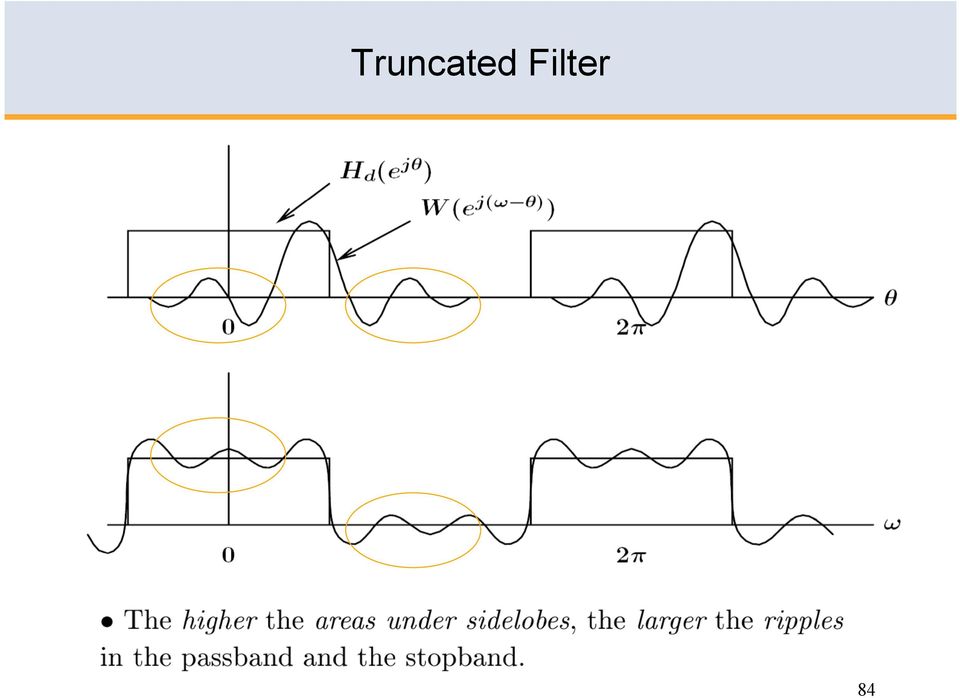
18 Truncated Filter 85

19 Ideal Requirements Ideally we would like to have small few computations close to a delta Dirac mass for to be close to our ideal low-pass filter These two requirements are conflicting! 86

20 Increasing the dimension of the window M M M M The width of the main lobe decreases as M increases M 87

21 Conflicting Ideal Requirements 88
22 Solution to Sharp Discontinuity of Rectangular Window Use windows with no abrupt discontinuity in their timedomain response and consequently low side-lobes in their frequency response. In this case, the reduced ripple comes at the expense of a wider transition region but this However, this can be compensated for by increasing the length of the filter. 89
23 Alternative Windows Time Domain Many alternatives have been proposed, e.g. Hanning Hamming Blackman 90
24 Windows Magnitude of Frequency Response 91
25 Summary of Windows Characteristics We see clearly that a wider transition region (wider main-lobe) is compensated by much lower side-lobes and thus less ripples. 92
26 Filter realised with rectangular/hanning windows Back to our ideal filter realised with rectangular window M=16 realised with Hanning window There are much less ripples for the Hanning window but that the transition width has increased M=16 93
27 Filter realised with Hanning windows realised with Hanning window M=16 realised with Hanning window M=40 Transition width can be improved by increasing the size of the Hanning window to M = 40 94
28 Windows characteristics Fundamental trade-off between main-lobe width and side-lobe amplitude As window smoother, peak side-lobe decreases, but the main-lobe width increases. Need to increase window length to achieve same transition bandwidth. 95
29 Specification necessary for Window Design Method ω c - cutoff frequency δ - maximum passband ripple Δω transition bandwidth Δω m width of the window mainlobe Response must not enter shaded regions 96
30 Key Property 1 of the Window Design Method 97
31 Key Property 2 of the Window Design Method 98
32 Key Property 3 of the Window Design Method 99
33 Key Property 4 of the Window Design Method 100
34 Key Property 5 of the Window Design Method 101
35 Passband / stopband ripples Passband / stopband ripples are often expressed in db: passband ripple = 20 log 10 (1+δ p ) db, or peak-to-peak passband ripple 20 log 10 (1+2δ p ) db; minimum stopband attenuation = -20 log 10 (δ s ) db. Example: δ p = 6% δ s = 0.01 peak-to-peak passband ripple 20 log 10 (1+2δ p ) = 1dB; minimum stopband attenuation = -20 log 10 (δ s ) = 40dB. The band-edge frequencies ω s and ω p are often called corner frequencies, particularly when associated with specified gain or attenuation (e.g. gain = -3dB). 102
36 Summary of Window Design Procedure Ideal frequency response has infinite impulse response To be implemented in practice it has to be truncated shifted to the right (to make is causal) Truncation is just pre-multiplication by a rectangular window the filter of a large order has a narrow transition band however, sharp discontinuity results in side-lobe interference independent of the filter s order and shape Gibbs phenomenon Windows with no abrupt discontinuity can be used to reduce Gibbs oscillations (e.g. Hanning, Hamming, Blackman) 103
37 Summary of the Key Properties of the Window Design Method 1. Equal transition bandwidth on both sides of the ideal cutoff frequency. 2. Equal peak approximation error in the pass-band and stopband. 3. Distance between approximation error peaks is approximately equal to the width of the window main-lobe. 4. The width of the main-lobe is wider than the transition band. approximation error peaks transition bandwidth mainlobe width 5. Peak approximation error is determined by the window shape, independent of the filter order. 104
38 Summary of the windowed FIR filter design procedure 1. Select a suitable window function 2. Specify an ideal response H d (ω) 3. Compute the coefficients of the ideal filter h d (n) 4. Multiply the ideal coefficients by the window function to give the filter coefficients 5. Evaluate the frequency response of the resulting filter and iterate if necessary (typically, it means increase M if the constraints you have been given have not been satisfied) 105
39 Step by Step Windowed Filter Design Example Design a type I low-pass filter according to the specification ω p =0.2π ω s =0.3π δ 1 =0.01 δ 2 =0.01 passband frequency stopband frequency 106
40 Step 1. Select a suitable window function Choosing a suitable window function can be done with the aid of published data such as The required peak error spec δ 2 = 0.01, i.e. -20log 10 (δ s ) = - 40 db Hanning window Main-lobe width ω s - ω p = 0.3π 0.2π = 0.1π, i.e. 0.1π = 8π / M filter length M 80, filter order N 79 Type-I filter have even order N = 80 although for Hanning window first and last ones are 0 so only 78 in reality 107
41 Step 2 Specify the Ideal Response Property 1: The band-edge frequency of the ideal response if the midpoint between ω s and ω p ω c = (ω s + ω p )/2 = (0.2π+0.3π)/2 = 0.25π 1 if ω 0.25π 0 if 0.25π < ω < π our ideal low-pass filter frequency response 108
42 Step 3 Compute the coefficients of the ideal filter The ideal filter coefficients h d are given by the Inverse Discrete time Fourier transform of H d (ω) Delayed impulse response (to make it causal) N Coefficients of the ideal filter
43 Step 3 Compute the coefficients of the ideal filter For our example this can be done analytically, but in general (for more complex H d (ω) functions) it will be computed approximately using an N-point Inverse Fast Fourier Transform (IFFT). Given a value of N (choice discussed later), create a sampled version of H d (ω): H d (p) = H d (2πp/N), p=0,1,...n-1. [ Note frequency spacing 2π/N rad/sample ] 110
44 Step 3 Compute the coefficients of the ideal filter If the Inverse FFT, and hence the filter coefficients, are to be purely realvalued, the frequency response must be conjugate symmetric: H d (-2πp/N) = H d * (2πp/N) (1) Since the Discrete Fourier Spectrum is also periodic, we see that H d (-2πp/N) = H d (2π - 2πp/N) = H d (2π(N-p)/N) (2) Equating (1) & (2) we must set H d (N-p) = H d * (p) for p = 1,..., (N/2-1). The Inverse FFT of H d* (p) is an N-sample time domain function h (n). For h (n) to be an accurate approximation of h(n), N must be made large enough to avoid time-domain aliasing of h(n), as illustrated below. 111
45 Consider FFT and IFFT Time domain aliasing The relationship (2) provides the reconstruction of the periodic signal x n however it does not imply that we can recover x n from the samples. For sequence x n of finite duration L this is only possible if N L 112
46 Step 4 Multiply to obtain the filter coefficients Coefficients of the ideal filter Multiplied by a Hamming window function 113
47 Step 5 Evaluate the Frequency Response and Iterate The frequency response is computed as the DFT of the filter coefficient vector. If the resulting filter does not meet the specifications, one of the following could be done adjust the ideal filter frequency response (for example, move the band edge) and repeat from step 2 adjust the filter length and repeat from step 4 change the window (and filter length) and repeat from step 4 114
48 Matlab Implementation of the Window Method Two methods FIR1 and FIR2 B=FIR2(N,F,M) Designs a Nth order FIR digital filter F and M specify frequency and magnitude breakpoints for the filter such that plot(n,f,m)shows a plot of desired frequency The frequencies F must be in increasing order between 0 and 1, with 1 corresponding to half the sample rate. B is the vector of length N+1, it is real, has linear phase and symmetric coefficients Default window is Hamming others can be specified 115
49 Multi-band Design 116
50 Frequency sampling method 117
51 FIR Filter Design Using Windows FIR filter design based on windows is simple and robust, however, it is not optimal: The resulting pass-band and stop-band parameters are equal even though often the specification is more strict in the stop band than in the pass band unnecessary high accuracy in the pass band The ripple of the window is not uniform (decays as we move away from discontinuity points according to side-lobe pattern of the window) by allowing more freedom in the ripple behaviour we may be able to reduce filter s order and hence its complexity 118
52 FIR Design by Optimisation: Least-Square Method We now present a method that approximates the desired frequency response by a linear-phase FIR amplitude function according to the following optimality criterion. The integral of the weighted square frequency-domain error is given by ε 2 = E 2 (ω)dω and we assume that the order and the type of the filter are known. Under this assumptions designing the FIR filter now reduces to determining the coefficients that would minimise ε
53 Recall Our Example Design a type I low-pass filter according to specification ω p =0.2π ω s =0.3π δ 1 =0.1 δ 2 =0.01 passband frequency stopband frequency But assume the pass-band tolerance of 0.1 The filter designed using window method cannot benefit from this relaxation, however, a least-square method design gives N = 33 (compared to N = 80). 120
54 Least-Square Design of FIR Filters Meeting the specification is not guaranteed a-priori, trial and error is often required. It might be useful to set the transition bands slightly narrower than needed, and it is often necessary to experiment with the weights Occasionally the resulting frequency response may be peculiar. Again, changing the weights would help to resolve the problem 121
55 Equiripple Design The least-square criterion of minimising ε 2 = E 2 (ω)dω is not entirely satisfactory. A better approach is to minimize the maximum error at each band ε = max ω E(ω) 122
56 Equiripple Design The method is optimal in a sense of minimising the maximum magnitude of the ripple in all bands of interest, the filter order is fixed It can be shown that this leads to an equiripple filter a filter which amplitude response oscillates uniformly between the tolerance bounds of each band 123
57 Equiripple Design Passband Many ripples achieve maximum Permitted amplitude Overall and passband-only frequency response of length 37 minimax filter
58 Remez method There exists a computational procedure known as the Remez method to solve this mathematical optimization problem. There are also exist formulae for estimating the required filter length in the case of lowpass, bandpass and narrow transition bandwidths. However, these formulae are not always reliable so it might be necessary to iterate the procedure so as to satisfy the design constraints. 125
59 Equiripple Design: Weights The weights can be determined in advance from a minimax specification. For example, if a simple lowpass filter has a requirement for the passband gain to be in the range 1- p to 1+ p, and the stopband gain to be less than s, the weightings given to the passband and stopband errors would be s and p respectively. The detailed algorithm is beyond the (time!) constraints of this module
60 Obtain the coefficients of an FIR lowpass digital filter to meet these specifications: passband edge frequency khz passband pk-to-pk ripple <1 db transition width Equiripple Design: Example 0.5 khz stopband attenuation >50 db sampling frequency 8 khz The passband ripple corresponds to ±6%, while the stopband attenuation is 0.32%, hence the weighting factors are set to 0.32 and 6. Using the relevant length estimation formula gives order N=25.8 hence N=26 was chosen, i.e. length =27. This proved to be substantially too short, and it was necessary to increase the order to 36 (length 37) to meet the specifications. 127
61 Equiripple Design: Matlab b = remez(n,f,m) designs an nth order FIR digital filter and returns the filter coefficients in length n+1 vector b. Vectors f and m specify the frequency and magnitude breakpoints [as for FIR2]. b = remez(n,f,m,w) uses vector w to specify weighting in each of the pass or stop bands in vectors f and m. Note again the frequency normalisation, where 1.0 equals half the sample rate. The call which finally met this filter specification was: h = remez(36,[ ]/4, [ ], [0.32 6]); The resulting frequency response is as shown previously:
62 The Parks-McClellan Remez exchange algorithm The computational procedure the optimization problem is by Remez The algorithm in common use is by Parks and McClellan. The Parks-McClellan Remez exchange algorithm is widely available and versatile. Important: it designs linear phase (symmetric) filters or antisymmetric filters of any of the standard types
63 Linear Symmetric Filters The frequency response of the direct form FIR filter may be rearranged by grouping the terms involving the first and last coefficients, the second and next to last, etc.: and then taking out a common factor exp( -jmω/2): If the filter length M+1 is odd, then the final term in curly brackets above is the single term b M/2, that is the centre coefficient ('tap') of the filter. 130
64 Symmetric impulse response Symmetric impulse response: if we put b M = b 0, b M-1 = b 1, etc., and note that exp(jθ) +exp(-jθ) = 2cos(θ), the frequency response becomes This is a purely real function (sum of cosines) multiplied by a linear phase term, hence the response has linear phase, corresponding to a pure delay of M/2 samples, ie half the filter length. A similar argument can be used to simplify antisymmetric impulse responses in terms of a sum of sine functions (such filters do not give a pure delay, although the phase still has a linear form π/2-mω/2)
65 Implementation of symmetric FIR filters The symmetric FIR filters of length N can be implemented using the folded delay line structure shown below, which uses N/2 (or (N+1)/2) multipliers rather than N
66 Limitations of the algorithm Linear phase in the stopbands is never a real requirement, and in some applications strictly linear phase in the passband is not needed either. The linear phase filters designed by this method are therefore longer than optimum non-linear phase filters. However, symmetric FIR filters of length N can be implemented using the folded delay line structure shown below, which uses N/2 (or (N+1)/2) multipliers rather than N, so the longer symmetric filter may be no more computationally intensive than a shorter non-linear phase one
67 Further options for FIR filter design More general non-linear optimisation (least squared error or minimax) can of course be used to design linear or non-linear phase FIR filters to meet more general frequency and/or time domain requirements. Matlab has suitable optimisation routines
Design of Efficient Digital Interpolation Filters for Integer Upsampling. Daniel B. Turek
 Design of Efficient Digital Interpolation Filters for Integer Upsampling by Daniel B. Turek Submitted to the Department of Electrical Engineering and Computer Science in partial fulfillment of the requirements
FFT Algorithms. Chapter 6. Contents 6.1
 Chapter 6 FFT Algorithms Contents Efficient computation of the DFT............................................ 6.2 Applications of FFT................................................... 6.6 Computing DFT
Frequency Response of FIR Filters
 Frequency Response of FIR Filters Chapter 6 This chapter continues the study of FIR filters from Chapter 5, but the emphasis is frequency response, which relates to how the filter responds to an input
Short-time FFT, Multi-taper analysis & Filtering in SPM12
 Short-time FFT, Multi-taper analysis & Filtering in SPM12 Computational Psychiatry Seminar, FS 2015 Daniel Renz, Translational Neuromodeling Unit, ETHZ & UZH 20.03.2015 Overview Refresher Short-time Fourier
Transition Bandwidth Analysis of Infinite Impulse Response Filters
 Transition Bandwidth Analysis of Infinite Impulse Response Filters Sujata Prabhakar Department of Electronics and Communication UCOE Punjabi University, Patiala Dr. Amandeep Singh Sappal Associate Professor
Analysis/resynthesis with the short time Fourier transform
 Analysis/resynthesis with the short time Fourier transform summer 2006 lecture on analysis, modeling and transformation of audio signals Axel Röbel Institute of communication science TU-Berlin IRCAM Analysis/Synthesis
The continuous and discrete Fourier transforms
 FYSA21 Mathematical Tools in Science The continuous and discrete Fourier transforms Lennart Lindegren Lund Observatory (Department of Astronomy, Lund University) 1 The continuous Fourier transform 1.1
First, we show how to use known design specifications to determine filter order and 3dB cut-off
 Butterworth Low-Pass Filters In this article, we describe the commonly-used, n th -order Butterworth low-pass filter. First, we show how to use known design specifications to determine filter order and
SIGNAL PROCESSING & SIMULATION NEWSLETTER
 1 of 10 1/25/2008 3:38 AM SIGNAL PROCESSING & SIMULATION NEWSLETTER Note: This is not a particularly interesting topic for anyone other than those who ar e involved in simulation. So if you have difficulty
ELEN E4810: Digital Signal Processing Topic 8: Filter Design: IIR
 ELEN E48: Digital Signal Processing Topic 8: Filter Design: IIR. Filter Design Specifications 2. Analog Filter Design 3. Digital Filters from Analog Prototypes . Filter Design Specifications The filter
SECTION 6 DIGITAL FILTERS
 SECTION 6 DIGITAL FILTERS Finite Impulse Response (FIR) Filters Infinite Impulse Response (IIR) Filters Multirate Filters Adaptive Filters 6.a 6.b SECTION 6 DIGITAL FILTERS Walt Kester INTRODUCTION Digital
SWISS ARMY KNIFE INDICATOR John F. Ehlers
 SWISS ARMY KNIFE INDICATOR John F. Ehlers The indicator I describe in this article does all the common functions of the usual indicators, such as smoothing and momentum generation. It also does some unusual
Digital Signal Processing IIR Filter Design via Impulse Invariance
 Digital Signal Processing IIR Filter Design via Impulse Invariance D. Richard Brown III D. Richard Brown III 1 / 11 Basic Procedure We assume here that we ve already decided to use an IIR filter. The basic
Filter Comparison. Match #1: Analog vs. Digital Filters
 CHAPTER 21 Filter Comparison Decisions, decisions, decisions! With all these filters to choose from, how do you know which to use? This chapter is a head-to-head competition between filters; we'll select
Sampling Theorem Notes. Recall: That a time sampled signal is like taking a snap shot or picture of signal periodically.
 Sampling Theorem We will show that a band limited signal can be reconstructed exactly from its discrete time samples. Recall: That a time sampled signal is like taking a snap shot or picture of signal
Sampling and Interpolation. Yao Wang Polytechnic University, Brooklyn, NY11201
 Sampling and Interpolation Yao Wang Polytechnic University, Brooklyn, NY1121 http://eeweb.poly.edu/~yao Outline Basics of sampling and quantization A/D and D/A converters Sampling Nyquist sampling theorem
Designing a Linear FIR filter
 Designing a Linear FIR filter implement the transfer function which can be in the form Leena Darsena, Himani of a program Agrawal or form of a circuit diagram. Abstract- Digital filtering has a very important
Em bedded DSP : I ntroduction to Digital Filters
 Embedded DSP : Introduction to Digital Filters 1 Em bedded DSP : I ntroduction to Digital Filters Digital filters are a important part of DSP. In fact their extraordinary performance is one of the keys
B3. Short Time Fourier Transform (STFT)
") B3. Short Time Fourier Transform (STFT) Objectives: Understand the concept of a time varying frequency spectrum and the spectrogram Understand the effect of different windows on the spectrogram; Understand
B3. Short Time Fourier Transform (STFT) Objectives: Understand the concept of a time varying frequency spectrum and the spectrogram Understand the effect of different windows on the spectrogram; Understand
Auto-Tuning Using Fourier Coefficients
 Auto-Tuning Using Fourier Coefficients Math 56 Tom Whalen May 20, 2013 The Fourier transform is an integral part of signal processing of any kind. To be able to analyze an input signal as a superposition
Final Year Project Progress Report. Frequency-Domain Adaptive Filtering. Myles Friel. Supervisor: Dr.Edward Jones
 Final Year Project Progress Report Frequency-Domain Adaptive Filtering Myles Friel 01510401 Supervisor: Dr.Edward Jones Abstract The Final Year Project is an important part of the final year of the Electronic
Appendix D Digital Modulation and GMSK
 D1 Appendix D Digital Modulation and GMSK A brief introduction to digital modulation schemes is given, showing the logical development of GMSK from simpler schemes. GMSK is of interest since it is used
Introduction to Digital Filters
 CHAPTER 14 Introduction to Digital Filters Digital filters are used for two general purposes: (1) separation of signals that have been combined, and (2) restoration of signals that have been distorted
Positive Feedback and Oscillators
 Physics 3330 Experiment #6 Fall 1999 Positive Feedback and Oscillators Purpose In this experiment we will study how spontaneous oscillations may be caused by positive feedback. You will construct an active
EECS 556 Image Processing W 09. Interpolation. Interpolation techniques B splines
 EECS 556 Image Processing W 09 Interpolation Interpolation techniques B splines What is image processing? Image processing is the application of 2D signal processing methods to images Image representation
Lab 1. The Fourier Transform
 Lab 1. The Fourier Transform Introduction In the Communication Labs you will be given the opportunity to apply the theory learned in Communication Systems. Since this is your first time to work in the
Applications of the DFT
 CHAPTER 9 Applications of the DFT The Discrete Fourier Transform (DFT) is one of the most important tools in Digital Signal Processing. This chapter discusses three common ways it is used. First, the DFT
The front end of the receiver performs the frequency translation, channel selection and amplification of the signal.
 Many receivers must be capable of handling a very wide range of signal powers at the input while still producing the correct output. This must be done in the presence of noise and interference which occasionally
UNIVERSITY OF CALIFORNIA, SAN DIEGO Electrical & Computer Engineering Department ECE 101 - Fall 2010 Linear Systems Fundamentals
 UNIVERSITY OF CALIFORNIA, SAN DIEGO Electrical & Computer Engineering Department ECE 101 - Fall 2010 Linear Systems Fundamentals FINAL EXAM WITH SOLUTIONS (YOURS!) You are allowed one 2-sided sheet of
ANALYZER BASICS WHAT IS AN FFT SPECTRUM ANALYZER? 2-1
 WHAT IS AN FFT SPECTRUM ANALYZER? ANALYZER BASICS The SR760 FFT Spectrum Analyzer takes a time varying input signal, like you would see on an oscilloscope trace, and computes its frequency spectrum. Fourier's
Electronic Communications Committee (ECC) within the European Conference of Postal and Telecommunications Administrations (CEPT)
 within the European Conference of Postal and Telecommunications Administrations (CEPT)") Page 1 Electronic Communications Committee (ECC) within the European Conference of Postal and Telecommunications Administrations (CEPT) ECC RECOMMENDATION (06)01 Bandwidth measurements using FFT techniques
Page 1 Electronic Communications Committee (ECC) within the European Conference of Postal and Telecommunications Administrations (CEPT) ECC RECOMMENDATION (06)01 Bandwidth measurements using FFT techniques
Controller Design in Frequency Domain
 ECSE 4440 Control System Engineering Fall 2001 Project 3 Controller Design in Frequency Domain TA 1. Abstract 2. Introduction 3. Controller design in Frequency domain 4. Experiment 5. Colclusion 1. Abstract
IIR Half-band Filter Design with TMS320VC33 DSP
 IIR Half-band Filter Design with TMS320VC33 DSP Ottó Nyári, Tibor Szakáll, Péter Odry Polytechnical Engineering College, Marka Oreskovica 16, Subotica, Serbia and Montenegro nyario@vts.su.ac.yu, tibi@vts.su.ac.yu,
T = 1 f. Phase. Measure of relative position in time within a single period of a signal For a periodic signal f(t), phase is fractional part t p
, phase is fractional part t p") Data Transmission Concepts and terminology Transmission terminology Transmission from transmitter to receiver goes over some transmission medium using electromagnetic waves Guided media. Waves are guided
Data Transmission Concepts and terminology Transmission terminology Transmission from transmitter to receiver goes over some transmission medium using electromagnetic waves Guided media. Waves are guided
Correlation and Convolution Class Notes for CMSC 426, Fall 2005 David Jacobs
 Correlation and Convolution Class otes for CMSC 46, Fall 5 David Jacobs Introduction Correlation and Convolution are basic operations that we will perform to extract information from images. They are in
DESIGN AND SIMULATION OF TWO CHANNEL QMF FILTER BANK FOR ALMOST PERFECT RECONSTRUCTION
 DESIGN AND SIMULATION OF TWO CHANNEL QMF FILTER BANK FOR ALMOST PERFECT RECONSTRUCTION Meena Kohli 1, Rajesh Mehra 2 1 M.E student, ECE Deptt., NITTTR, Chandigarh, India 2 Associate Professor, ECE Deptt.,
Understanding CIC Compensation Filters
 Understanding CIC Compensation Filters April 2007, ver. 1.0 Application Note 455 Introduction f The cascaded integrator-comb (CIC) filter is a class of hardware-efficient linear phase finite impulse response
Frequency Response of Filters
 School of Engineering Department of Electrical and Computer Engineering 332:224 Principles of Electrical Engineering II Laboratory Experiment 2 Frequency Response of Filters 1 Introduction Objectives To
chapter Introduction to Digital Signal Processing and Digital Filtering 1.1 Introduction 1.2 Historical Perspective
 Introduction to Digital Signal Processing and Digital Filtering chapter 1 Introduction to Digital Signal Processing and Digital Filtering 1.1 Introduction Digital signal processing (DSP) refers to anything
This document is downloaded from DR-NTU, Nanyang Technological University Library, Singapore.
 This document is downloaded from DR-NTU, Nanyang Technological University Library, Singapore. Title Transcription of polyphonic signals using fast filter bank( Accepted version ) Author(s) Foo, Say Wei;
The Fourier Analysis Tool in Microsoft Excel
 The Fourier Analysis Tool in Microsoft Excel Douglas A. Kerr Issue March 4, 2009 ABSTRACT AD ITRODUCTIO The spreadsheet application Microsoft Excel includes a tool that will calculate the discrete Fourier
Impedance 50 (75 connectors via adapters)
") VECTOR NETWORK ANALYZER PLANAR TR1300/1 DATA SHEET Frequency range: 300 khz to 1.3 GHz Measured parameters: S11, S21 Dynamic range of transmission measurement magnitude: 130 db Measurement time per point:
VECTOR NETWORK ANALYZER PLANAR TR1300/1 DATA SHEET Frequency range: 300 khz to 1.3 GHz Measured parameters: S11, S21 Dynamic range of transmission measurement magnitude: 130 db Measurement time per point:
The Algorithms of Speech Recognition, Programming and Simulating in MATLAB
 FACULTY OF ENGINEERING AND SUSTAINABLE DEVELOPMENT. The Algorithms of Speech Recognition, Programming and Simulating in MATLAB Tingxiao Yang January 2012 Bachelor s Thesis in Electronics Bachelor s Program
HYBRID FIR-IIR FILTERS By John F. Ehlers
 HYBRID FIR-IIR FILTERS By John F. Ehlers Many traders have come to me, asking me to make their indicators act just one day sooner. They are convinced that this is just the edge they need to make a zillion
Aliasing, Image Sampling and Reconstruction
 Aliasing, Image Sampling and Reconstruction Recall: a pixel is a point It is NOT a box, disc or teeny wee light It has no dimension It occupies no area It can have a coordinate More than a point, it is
Lecture 6 - Design of Digital Filters
 Lecture 6 - Design of Digital Filters 6.1 Simple filters There are two methods for smoothing a sequence of numbers in order to approximate a low-pass filter: the polynomial fit, as just described, and
73M2901CE Programming the Imprecise Call Progress Monitor Filter
 A Maxim Integrated Products Brand 73M2901CE Programming the Imprecise Call Progress Monitor Filter APPLICATION NOTE AN_2901CE_042 March 2009 Introduction The Teridian 73M2901CE integrated circuit modem
Agilent Time Domain Analysis Using a Network Analyzer
 Agilent Time Domain Analysis Using a Network Analyzer Application Note 1287-12 0.0 0.045 0.6 0.035 Cable S(1,1) 0.4 0.2 Cable S(1,1) 0.025 0.015 0.005 0.0 1.0 1.5 2.0 2.5 3.0 3.5 4.0 Frequency (GHz) 0.005
Lecture 8 ELE 301: Signals and Systems
 Lecture 8 ELE 3: Signals and Systems Prof. Paul Cuff Princeton University Fall 2-2 Cuff (Lecture 7) ELE 3: Signals and Systems Fall 2-2 / 37 Properties of the Fourier Transform Properties of the Fourier
Clutter Filter Design for Ultrasound Color Flow Imaging
 Clutter Filter Design for Ultrasound Color Flow Imaging by Steinar Bjærum (Corresponding author) Department of Physiology and Biomedical Engineering Norwegian University of Science and Technology Trondheim,
CHAPTER 6 Frequency Response, Bode Plots, and Resonance
 ELECTRICAL CHAPTER 6 Frequency Response, Bode Plots, and Resonance 1. State the fundamental concepts of Fourier analysis. 2. Determine the output of a filter for a given input consisting of sinusoidal
TTT4110 Information and Signal Theory Solution to exam
 Norwegian University of Science and Technology Department of Electronics and Telecommunications TTT4 Information and Signal Theory Solution to exam Problem I (a The frequency response is found by taking
CHAPTER 8 ANALOG FILTERS
 ANALOG FILTERS CHAPTER 8 ANALOG FILTERS SECTION 8.: INTRODUCTION 8. SECTION 8.2: THE TRANSFER FUNCTION 8.5 THE SPLANE 8.5 F O and Q 8.7 HIGHPASS FILTER 8.8 BANDPASS FILTER 8.9 BANDREJECT (NOTCH) FILTER
USB 3.0 CDR Model White Paper Revision 0.5
 USB 3.0 CDR Model White Paper Revision 0.5 January 15, 2009 INTELLECTUAL PROPERTY DISCLAIMER THIS WHITE PAPER IS PROVIDED TO YOU AS IS WITH NO WARRANTIES WHATSOEVER, INCLUDING ANY WARRANTY OF MERCHANTABILITY,
Application Note: Spread Spectrum Oscillators Reduce EMI for High Speed Digital Systems
 Application Note: Spread Spectrum Oscillators Reduce EMI for High Speed Digital Systems Introduction to Electro-magnetic Interference Design engineers seek to minimize harmful interference between components,
8 Filtering. 8.1 Mathematical operation
 8 Filtering The estimated spectrum of a time series gives the distribution of variance as a function of frequency. Depending on the purpose of analysis, some frequencies may be of greater interest than
Analog Filters. A common instrumentation filter application is the attenuation of high frequencies to avoid frequency aliasing in the sampled data.
 Analog Filters Filters can be used to attenuate unwanted signals such as interference or noise or to isolate desired signals from unwanted. They use the frequency response of a measuring system to alter
SGN-1158 Introduction to Signal Processing Test. Solutions
 SGN-1158 Introduction to Signal Processing Test. Solutions 1. Convolve the function ( ) with itself and show that the Fourier transform of the result is the square of the Fourier transform of ( ). (Hints:
The Effective Number of Bits (ENOB) of my R&S Digital Oscilloscope Technical Paper
 of my R&S Digital Oscilloscope Technical Paper") The Effective Number of Bits (ENOB) of my R&S Digital Oscilloscope Technical Paper Products: R&S RTO1012 R&S RTO1014 R&S RTO1022 R&S RTO1024 This technical paper provides an introduction to the signal
The Effective Number of Bits (ENOB) of my R&S Digital Oscilloscope Technical Paper Products: R&S RTO1012 R&S RTO1014 R&S RTO1022 R&S RTO1024 This technical paper provides an introduction to the signal
Introduction to IQ-demodulation of RF-data
 Introduction to IQ-demodulation of RF-data by Johan Kirkhorn, IFBT, NTNU September 15, 1999 Table of Contents 1 INTRODUCTION...3 1.1 Abstract...3 1.2 Definitions/Abbreviations/Nomenclature...3 1.3 Referenced
(Refer Slide Time: 01:11-01:27)
") Digital Signal Processing Prof. S. C. Dutta Roy Department of Electrical Engineering Indian Institute of Technology, Delhi Lecture - 6 Digital systems (contd.); inverse systems, stability, FIR and IIR,
Digital Signal Processing Prof. S. C. Dutta Roy Department of Electrical Engineering Indian Institute of Technology, Delhi Lecture - 6 Digital systems (contd.); inverse systems, stability, FIR and IIR,
RADIO FREQUENCY INTERFERENCE AND CAPACITY REDUCTION IN DSL
 RADIO FREQUENCY INTERFERENCE AND CAPACITY REDUCTION IN DSL Padmabala Venugopal, Michael J. Carter*, Scott A. Valcourt, InterOperability Laboratory, Technology Drive Suite, University of New Hampshire,
AN-837 APPLICATION NOTE
 APPLICATION NOTE One Technology Way P.O. Box 916 Norwood, MA 262-916, U.S.A. Tel: 781.329.47 Fax: 781.461.3113 www.analog.com DDS-Based Clock Jitter Performance vs. DAC Reconstruction Filter Performance
A FIR FILTER DESIGN TOOL USING GENETIC ALGORITHMS
 Anais do XXXIV COBENGE. Passo Fundo: Ed. Universidade de Passo Fundo, Setembro de 006. ISBN 85-755-37-4 A FIR FILTER DESIGN TOOL USING GENETIC ALGORITHMS André Macário Barros andre_barros@superig.com.br
Probability and Random Variables. Generation of random variables (r.v.)
") Probability and Random Variables Method for generating random variables with a specified probability distribution function. Gaussian And Markov Processes Characterization of Stationary Random Process Linearly
Probability and Random Variables Method for generating random variables with a specified probability distribution function. Gaussian And Markov Processes Characterization of Stationary Random Process Linearly
Lecture 9. Poles, Zeros & Filters (Lathi 4.10) Effects of Poles & Zeros on Frequency Response (1) Effects of Poles & Zeros on Frequency Response (3)
 Effects of Poles & Zeros on Frequency Response (1) Effects of Poles & Zeros on Frequency Response (3)") Effects of Poles & Zeros on Frequency Response (1) Consider a general system transfer function: zeros at z1, z2,..., zn Lecture 9 Poles, Zeros & Filters (Lathi 4.10) The value of the transfer function
Effects of Poles & Zeros on Frequency Response (1) Consider a general system transfer function: zeros at z1, z2,..., zn Lecture 9 Poles, Zeros & Filters (Lathi 4.10) The value of the transfer function
Agilent AN 1316 Optimizing Spectrum Analyzer Amplitude Accuracy
 Agilent AN 1316 Optimizing Spectrum Analyzer Amplitude Accuracy Application Note RF & Microwave Spectrum Analyzers Table of Contents 3 3 4 4 5 7 8 8 13 13 14 16 16 Introduction Absolute versus relative
Implementation of Digital Signal Processing: Some Background on GFSK Modulation
 Implementation of Digital Signal Processing: Some Background on GFSK Modulation Sabih H. Gerez University of Twente, Department of Electrical Engineering s.h.gerez@utwente.nl Version 4 (February 7, 2013)
Non-Data Aided Carrier Offset Compensation for SDR Implementation
 Non-Data Aided Carrier Offset Compensation for SDR Implementation Anders Riis Jensen 1, Niels Terp Kjeldgaard Jørgensen 1 Kim Laugesen 1, Yannick Le Moullec 1,2 1 Department of Electronic Systems, 2 Center
TCOM 370 NOTES 99-4 BANDWIDTH, FREQUENCY RESPONSE, AND CAPACITY OF COMMUNICATION LINKS
 TCOM 370 NOTES 99-4 BANDWIDTH, FREQUENCY RESPONSE, AND CAPACITY OF COMMUNICATION LINKS 1. Bandwidth: The bandwidth of a communication link, or in general any system, was loosely defined as the width of
1.4 Fast Fourier Transform (FFT) Algorithm
 Algorithm") 74 CHAPTER AALYSIS OF DISCRETE-TIME LIEAR TIME-IVARIAT SYSTEMS 4 Fast Fourier Transform (FFT Algorithm Fast Fourier Transform, or FFT, is any algorithm for computing the -point DFT with a computational
74 CHAPTER AALYSIS OF DISCRETE-TIME LIEAR TIME-IVARIAT SYSTEMS 4 Fast Fourier Transform (FFT Algorithm Fast Fourier Transform, or FFT, is any algorithm for computing the -point DFT with a computational
1.1 Discrete-Time Fourier Transform
 1.1 Discrete-Time Fourier Transform The discrete-time Fourier transform has essentially the same properties as the continuous-time Fourier transform, and these properties play parallel roles in continuous
SIGNAL PROCESSING FOR EFFECTIVE VIBRATION ANALYSIS
 SIGNAL PROCESSING FOR EFFECTIVE VIBRATION ANALYSIS Dennis H. Shreve IRD Mechanalysis, Inc Columbus, Ohio November 1995 ABSTRACT Effective vibration analysis first begins with acquiring an accurate time-varying
Analog and Digital Signals, Time and Frequency Representation of Signals
 1 Analog and Digital Signals, Time and Frequency Representation of Signals Required reading: Garcia 3.1, 3.2 CSE 3213, Fall 2010 Instructor: N. Vlajic 2 Data vs. Signal Analog vs. Digital Analog Signals
1995 Mixed-Signal Products SLAA013
 Application Report 995 Mixed-Signal Products SLAA03 IMPORTANT NOTICE Texas Instruments and its subsidiaries (TI) reserve the right to make changes to their products or to discontinue any product or service
Digital filter design for electrophysiological data a practical approach
 NOTICE: this is the author s version of a work that was accepted for publication in the Journal of Neuroscience Methods following peer review. Changes resulting from the publishing process, such as editing,
SUMMARY. Additional Digital/Software filters are included in Chart and filter the data after it has been sampled and recorded by the PowerLab.
 This technique note was compiled by ADInstruments Pty Ltd. It includes figures and tables from S.S. Young (2001): Computerized data acquisition and analysis for the life sciences. For further information
2.161 Signal Processing: Continuous and Discrete Fall 2008
 MT OpenCourseWare http://ocw.mit.edu.6 Signal Processing: Continuous and Discrete Fall 00 For information about citing these materials or our Terms of Use, visit: http://ocw.mit.edu/terms. MASSACHUSETTS
FAST Fourier Transform (FFT) and Digital Filtering Using LabVIEW
 and Digital Filtering Using LabVIEW") FAST Fourier Transform (FFT) and Digital Filtering Using LabVIEW Wei Lin Department of Biomedical Engineering Stony Brook University Instructor s Portion Summary This experiment requires the student to
FAST Fourier Transform (FFT) and Digital Filtering Using LabVIEW Wei Lin Department of Biomedical Engineering Stony Brook University Instructor s Portion Summary This experiment requires the student to
Motorola Digital Signal Processors
 Motorola Digital Signal Processors Principles of Sigma-Delta Modulation for Analog-to- Digital Converters by Sangil Park, Ph. D. Strategic Applications Digital Signal Processor Operation MOTOROLA APR8
AN1200.04. Application Note: FCC Regulations for ISM Band Devices: 902-928 MHz. FCC Regulations for ISM Band Devices: 902-928 MHz
 AN1200.04 Application Note: FCC Regulations for ISM Band Devices: Copyright Semtech 2006 1 of 15 www.semtech.com 1 Table of Contents 1 Table of Contents...2 1.1 Index of Figures...2 1.2 Index of Tables...2
S. Boyd EE102. Lecture 1 Signals. notation and meaning. common signals. size of a signal. qualitative properties of signals.
 S. Boyd EE102 Lecture 1 Signals notation and meaning common signals size of a signal qualitative properties of signals impulsive signals 1 1 Signals a signal is a function of time, e.g., f is the force
Use bandpass filters to discriminate against wide ranges of frequencies outside the passband.
 Microwave Filter Design Chp6. Bandstop Filters Prof. Tzong-Lin Wu Department of Electrical Engineering National Taiwan University Bandstop Filters Bandstop filter V.S. Bandpass filter Use bandpass filters
SOFTWARE FOR GENERATION OF SPECTRUM COMPATIBLE TIME HISTORY
 3 th World Conference on Earthquake Engineering Vancouver, B.C., Canada August -6, 24 Paper No. 296 SOFTWARE FOR GENERATION OF SPECTRUM COMPATIBLE TIME HISTORY ASHOK KUMAR SUMMARY One of the important
Sophomore Physics Laboratory (PH005/105)
") CALIFORNIA INSTITUTE OF TECHNOLOGY PHYSICS MATHEMATICS AND ASTRONOMY DIVISION Sophomore Physics Laboratory (PH5/15) Analog Electronics Active Filters Copyright c Virgínio de Oliveira Sannibale, 23 (Revision
CALIFORNIA INSTITUTE OF TECHNOLOGY PHYSICS MATHEMATICS AND ASTRONOMY DIVISION Sophomore Physics Laboratory (PH5/15) Analog Electronics Active Filters Copyright c Virgínio de Oliveira Sannibale, 23 (Revision
The Z transform (3) 1
 1") The Z transform (3) 1 Today Analysis of stability and causality of LTI systems in the Z domain The inverse Z Transform Section 3.3 (read class notes first) Examples 3.9, 3.11 Properties of the Z Transform
The Z transform (3) 1 Today Analysis of stability and causality of LTI systems in the Z domain The inverse Z Transform Section 3.3 (read class notes first) Examples 3.9, 3.11 Properties of the Z Transform
TTT4120 Digital Signal Processing Suggested Solution to Exam Fall 2008
 Norwegian University of Science and Technology Department of Electronics and Telecommunications TTT40 Digital Signal Processing Suggested Solution to Exam Fall 008 Problem (a) The input and the input-output
Time series analysis Matlab tutorial. Joachim Gross
 Time series analysis Matlab tutorial Joachim Gross Outline Terminology Sampling theorem Plotting Baseline correction Detrending Smoothing Filtering Decimation Remarks Focus on practical aspects, exercises,
How to Design 10 khz filter. (Using Butterworth filter design) Application notes. By Vadim Kim
 Application notes. By Vadim Kim") How to Design 10 khz filter. (Using Butterworth filter design) Application notes. By Vadim Kim This application note describes how to build a 5 th order low pass, high pass Butterworth filter for 10 khz
How to Design 10 khz filter. (Using Butterworth filter design) Application notes. By Vadim Kim This application note describes how to build a 5 th order low pass, high pass Butterworth filter for 10 khz
Chapter 8 - Power Density Spectrum
 EE385 Class Notes 8/8/03 John Stensby Chapter 8 - Power Density Spectrum Let X(t) be a WSS random process. X(t) has an average power, given in watts, of E[X(t) ], a constant. his total average power is
L9: Cepstral analysis
 L9: Cepstral analysis The cepstrum Homomorphic filtering The cepstrum and voicing/pitch detection Linear prediction cepstral coefficients Mel frequency cepstral coefficients This lecture is based on [Taylor,
More Filter Design on a Budget
 Application Report SLOA096 December 2001 More Filter Design on a Budget Bruce Carter High Performance Linear Products ABSTRACT This document describes filter design from the standpoint of cost. Filter
Implementation of the LMS Algorithm for Noise Cancellation on Speech Using the ARM LPC2378 Processor.
 School of Mathematics and Systems Engineering Reports from MSI - Rapporter från MSI Implementation of the LMS Algorithm for Noise Cancellation on Speech Using the ARM LPC2378 Processor. Cesar Augusto Azurdia
Voice---is analog in character and moves in the form of waves. 3-important wave-characteristics:
 Voice Transmission --Basic Concepts-- Voice---is analog in character and moves in the form of waves. 3-important wave-characteristics: Amplitude Frequency Phase Voice Digitization in the POTS Traditional
14: FM Radio Receiver
 (1) (2) (3) DSP and Digital Filters (2015-7310) FM Radio: 14 1 / 12 (1) (2) (3) FM spectrum: 87.5 to 108 MHz Each channel: ±100 khz Baseband signal: Mono (L + R): ±15kHz Pilot tone: 19 khz Stereo (L R):
MATH 4330/5330, Fourier Analysis Section 11, The Discrete Fourier Transform
 MATH 433/533, Fourier Analysis Section 11, The Discrete Fourier Transform Now, instead of considering functions defined on a continuous domain, like the interval [, 1) or the whole real line R, we wish
Spectral Analysis Using a Deep-Memory Oscilloscope Fast Fourier Transform (FFT)
") Spectral Analysis Using a Deep-Memory Oscilloscope Fast Fourier Transform (FFT) For Use with Infiniium 54830B Series Deep-Memory Oscilloscopes Application Note 1383-1 Table of Contents Introduction........................
Spectral Analysis Using a Deep-Memory Oscilloscope Fast Fourier Transform (FFT) For Use with Infiniium 54830B Series Deep-Memory Oscilloscopes Application Note 1383-1 Table of Contents Introduction........................
Loop Bandwidth and Clock Data Recovery (CDR) in Oscilloscope Measurements. Application Note 1304-6
 in Oscilloscope Measurements. Application Note 1304-6") Loop Bandwidth and Clock Data Recovery (CDR) in Oscilloscope Measurements Application Note 1304-6 Abstract Time domain measurements are only as accurate as the trigger signal used to acquire them. Often
Loop Bandwidth and Clock Data Recovery (CDR) in Oscilloscope Measurements Application Note 1304-6 Abstract Time domain measurements are only as accurate as the trigger signal used to acquire them. Often
Laboratory #5: RF Filter Design
 EEE 194 RF Laboratory Exercise 5 1 Laboratory #5: RF Filter Design I. OBJECTIVES A. Design a third order low-pass Chebyshev filter with a cutoff frequency of 330 MHz and 3 db ripple with equal terminations