Competence in Functional Safety MANUAL. Functional safety of globe valves, rotary plug valves, ball valves and butterfly valves
|
|
|
- Arleen Strickland
- 7 years ago
- Views:
Transcription
1 MANUAL Functional safety of globe valves, rotary plug valves, ball valves and butterfly valves

2 SAMSON GROUP Table of contents Scope... 4 Validity of this manual... 4 Intended use of this manual... 5 General aspects of functional safety Standards, terms and abbreviations Determining the safety integrity level Hardware fault tolerance Intended use of control valves in safety-instrumented systems General valve requirements Globe valve requirements Ball valve requirements Butterfly valves requirements Rotary plug valves requirements Proof tests and service life Installation, piping and wiring Mechanical and pneumatic installation Electrical installation Installation of control valves Applicable device documentation Appendix 1 Manufacturer s declarations Appendix 2 Example of a checklist for a final element

3 1 Scope 3 Intended use of this manual Valves and the associated actuators are used to isolate pipelines in safety-instrumented systems. Alternatively, they can also be used for pressure relief, i.e. by completely opening valves. 2 Validity of this manual This manual applies to control valves manufactured by the following companies within the SAMSON GROUP: SAMSON AG LEUSCH GmbH Industriearmaturen Pfeiffer Chemie-Armaturenbau GmbH VETEC Ventiltechnik GmbH This manual is intended to assist planners and operators during the integration of control valves into a safety loop as part of the safety function and to enable them to safely operate control valves. This manual contains information, safety-related data and warnings concerning the functional safety in accordance with IEC and concerning the application in the process industry in accordance with IEC It does not contain any particular details on other safety requirements, such as explosion protection or electrical safety. Safety-instrumented systems are to be commissioned and maintained by qualified personnel only. Refer to the corresponding mounting and operating instructions of the valve. Refer to the manufacturer s declarations in Appendix 1 of this manual for the valve models concerned. The individual versions of the valves can be identified by their nameplates SAMSON Made in Germany 1 CE marking or "Art. 3, Abs.3" (see article 3, 3 of PED), where applicable 2 Identification no. of notified body, fluid group and category, where applicable 3 Type designation 4 Modification index of valve 5 Material 6 Year of manufacture 7 Nominal size: DIN: DN, ANSI: NPS 8 Permissible excess pressure at room temperature DIN: PN, ANSI: CL 9 Order number with modification index 10 Position of item in order 11 Flow coefficient: DIN: KVS, ANSI: CV 12 Characteristic: % equal percentage, Lin linear, DIN: A/Z quick opening,, ANSI: O/C 13 Sealing: ME metal, ST stellited, Ni nickel-plated PT soft sealing with PTFE, PK soft sealing with PEEK 14 Pressure-balanced: DIN: D, ANSI: B 15 I or III flow divider Fig. 8 Valve nameplate (left) and actuator nameplates (right) 1 Type designation 2 Modification index 3 Effective diaphragm area 4 Fail-safe action: FA Actuator stem extends FE Actuator stem retracts 5 Travel 6 Bench range (spring range) 7 Bench range with preloaded springs SAMSON Model - No. Serial - No. Pneum. Stellantrieb Pneum. actuator 3 Servo - monteur pneum. Federbereich Spring range Plage des ressorts Stelldruckbereich Signal pressure range Plage avec précontrainte cm² Hub Stroke Course Zuluft max. 6 bar Begrenzt auf Air supply 90 psi Up to Air d' alimentation Limitéà Made in France 1 bar mm bar bar Example of a nameplate for a Type 3241 Valve with Type 3271 or Type 3277 Pneumatic Actuator manufactured by SAMSON AG 4 5

4 4 General aspects of functional safety 4.1 Standards, terms and abbreviations Abbreviation Designation Description SIL Safety Integrity Level One of four discrete levels for specifying the safety integrity requirements of the safety functions to be allocated to the E/E/ PE safety-related systems, where SIL 4 has the highest level of safety integrity and SIL 1 has the lowest. MTBF Mean Time Between Failures Mean time between two failures MTTR Mean Time To Restoration Mean time between the occurrence of a failure in a device or system and its repair HFT Hardware Fault Tolerance Capability of a functional unit to continue executing the demanded function in case of faults or deviations. λ sd Failure rate for all safe detected failures λ su Failure rate for all safe undetected failures λ dd Failure rate for all dangerous detected failures λ du Failure rate for all dangerous undetected failures SFF Safe Failure Fraction Fraction of non-hazardous failures, i.e. the fraction of failures without the potential to set the safety-related system to a dangerous or impermissible state. PFDavg T I Low demand mode Average Probability of Failure on Demand Test interval between life testing of the safety function Low demand mode of operation Average likelihood that a dangerous safety function failures occurs on demand. Time interval between functional tests of the safety function Low demand mode is where the frequency of demands for operation made on a safety-related system is no greater than one per year and no greater than twice the proof test frequency. Abbreviation Designation Description MooN Voting M out of N (e.g. 2oo3) Classification and description of the safety-related system regarding redundancy and the selection procedure used. N indicates how often the safety function is carried out (redundancy). M determines how many channels must work properly. Example: Pressure measurement in 1oo2 architecture A safety-instrumented system decides that a specified pressure limit has been exceeded if one of two pressure sensors reaches this limit. In a 1oo1 architecture, there is only one pressure sensor. MooND Voting M out of N with diagnostics Relevant standards Norm IEC Parts 1 to 7 IEC Parts 1 to 3 VDI 2180 Parts 1 to 5 Terms and definitions Term Dangerous failure Safety-related system Safety function Designation Functional safety of electrical/ electronic/programmable electronic safety-related systems Functional safety Safety instrumented systems for the process industry sector Safeguarding of industrial process plants by means of process control engineering Definition Failure with the potential to set the safety-related system to a dangerous or inoperative state. A safety-related system carries out the safety functions needed to establish or maintain a safe state, e.g. in a plant. Example: Pressure measuring instrument, logic unit (e.g. limit switch) and valve form a safety-related system. A defined function carried out by a safety-related system in order to establish or maintain a safe state of the plant, under consideration of a specified dangerous incident. Example: Pressure limit monitoring 6 7

5 4.2 Determining the safety integrity level 4.3 Hardware fault tolerance The achievable safety integrity level (SIL) is determined by the following safety-related data: Average probability of failure on demand (PFDavg) Hardware fault tolerance (HFT) Safe failure fraction (SFF) The following table in accordance with IEC and IEC shows how the safety integrity level (SIL) depends on the average probability of failure on demand (PFDavg). It is based on low demand mode of operation, i.e. the frequency of demands on a safety-related system is no greater than once per year. Safety integrity level (SIL) PFDavg (low demand mode) to < to < to < to < 10-1 PFDavg in low demand mode of operation according to IEC , Table 2 The sensor, logic unit and final element form a safety-related system that performs a safety function. Sensor e.g. pressure measuring instrument Logic unit e.g. PLC Final element e.g. valve PFDavg X % X % X % In the process industry, the achievable SIL classes for sensors, final elements and non-programmable logic modules, such as isolating amplifiers and relays, are restricted in accordance with IEC as shown in the following table. Safety integrity level (SIL) Minimum required hardware failure tolerance (HFT) Special requirements (refer to IEC 61508) Minimum required hardware failure tolerance (HFT) according to IEC , Table 6, for the process industry The minimum required hardware failure tolerance can be decreased by one if the following requirements are met: The device is proven in use. Take this into account when selecting devices! The device only allows process-relevant parameters to be set, e.g. measuring range, upscale or downscale function in case of failure. Final elements do not have any configurable functions. The process-relevant parameters of the device are access-protected, e.g. by jumper or password. Final elements do not have any configurable functions. The function requires a SIL less than 4. A final element has a single-channel design, resulting in a hardware failure tolerance (HFT) = 0. This results in a single-channel application up to SIL 1 or up to SIL 2 for proven-in-use devices. A HFT = 2, as required to achieve SIL 3, can be achieved by redundant architecture (several final elements with SIL 2). The average probability of failure on demand (PFDavg = sum of sensor, logic unit and final element failures) must be within the range of the demanded safety integrity level (SIL) in case of demand as listed in the above table. A single-channel application in SIL 3 is only possible when special analysis of the application is made by applying additional measures (e.g. diagnostics). 8 9
. It is based on low demand mode of operation, i.e. the frequency of demands on a safety-related system is no greater than once per year.")
6 5 Intended use of control valves in safety-instrumented systems Responsibility The reliability of mechanical components is significantly affected by the operating conditions and, as a result, by systematic failures. This needs to be taken into account when selecting and sizing devices. Safety-instrumented function During normal operation, the signal pressure is applied to the pneumatic actuator. To meet the requirements of the safety-instrumented function, the actuator is usually vented by a solenoid valve. The force of the actuator springs moves the valve to its end position, i.e. the valve is either completely opened or closed. To reduce systematic failure, diverse redundancies may be advantageous (e.g. globe valve and ball valve). The joint use of a control valve within the safety loop by a control loop of a basic process control system makes it possible to increase the diagnostic coverage of the safety-instrumented system. This joint use can lead to additional risk. This aspect must be taken into account in the risk analysis. Online tests, such as the partial stroke test and other diagnostic processes integrated into the valve positioner, can be regarded as state-of-the-art test methods. They can be used to lengthen the proof test interval or to improve the safety margin (discovery of undetected systematic failures). Responsibility The end position of the valve must not be impeded by mechanical equipment, such as travel stops or handwheels, under any circumstances. When the signal pressure is applied to the actuator again, the valve moves to the corresponding position. If the actuator is to be locked after a case of demand, this must be ensured by the operator using suitable means. Features of final elements Contact with the process media may cause systematic failure and, as a result, affect the safety-related availability of the safety-instrumented systems. The influence of specific process conditions must be analyzed and taken into account during sizing and maintenance. These conditions arise from process requirements. To rule out systematic failure, we recommend creating a loop data sheet according to the German standard VDI , section 4 (recommendations for final elements). In case of doubt, consult the manufacturer for valve sizing. VDI , section 4 provides special instructions. Avoiding systematic failure To avoid systematic failure, the user must take into account the following applicationspecific factors besides the manufacturer specifications: Corrosion (destruction primarily of metals due to chemical and physical processes) Material fatigue, e.g. in bellows seals Wear induced by the process medium Abrasion (material removed by solids contained in the process medium) Medium deposits Aging (damage caused to organic materials, e.g. plastics or elastomers, by exposure to light and heat) Chemical attack (organic materials, e.g. plastics or elastomers, which swell, leach out or decompose due to exposure to chemicals) If no experience data exist for the devices used, a visual inspection of the safety equipment must be performed after a short time in operation

7 5.1 General control valve requirements Responsibility 5.2 Globe valve requirements Responsibility For each application, the user must specify the following conditions: Maximum/minimum transit time OPEN CLOSED or CLOSED OPEN Permissible leakage rate Maximum/minimum supply pressure of the compressed air network Air capacity available in relation to pressure Connecting pipe cross-sections must be adhered to. Nominal size (connection length 2 m) K VS coefficient Manufacturer If there is a risk of solids contained in the process medium causing blockage, a strainer must be fitted. Safety equipment with fail-open action must not be operated with strainers. To reduce friction, it is preferable to use spring-loaded stem packings. Adjustable stem packings are to be tightened by qualified staff only to prevent the stem from becoming blocked Connection Pressure (bar) 4 1 and DN 6 DN 8 DN 10 To prevent corrosion of the actuator springs, measures must be taken to prevent water or moisture from entering the actuator. Such measures include fitting a venting pipe or air purging of the actuator s spring chamber. 2.5 DN 6 DN 8 DN 4 6 DN 4 DN 6 DN 4 Note: A larger nominal size is needed when the connection length exceeds 2 m. Example: Connecting pipe cross-sections required for SAMSOMATIC Type 3963 Solenoid Valve SAMSON uses calculation methods to predict the transit time and to size the pneumatic hook-up. SAMSON can support users in selecting devices on request. The seat shut-off performance (leakage rate) must be tested at regular intervals by performing plausibility checks while the process is running or measuring it on a leakage test bench. The type of test depends on the application. Manufacturer Example: Control and quick-acting shut-off valve with air purging of the actuator s spring chamber Example: On-off valve with air purging of the actuator s spring chamber Suitable measures must be taken to ensure that the venting port of the solenoid valve is kept open. Manufacturer/ operator The external leakage (fugitive emissions) must be tested at regular intervals, e.g. by spraying with foaming agent. The conditions depend on the process requirements. Example: Venting pipe on the solenoid valve 12 13
 K VS coefficient Manufacturer If there is a risk of solids contained in the process medium causing blockage, a strainer must be fitted.")
8 It is essential to check the actuator forces to ensure that the valve can Responsibility 5.3 Ball valve requirements Responsibility overcome the process pressures to reach its fail-safe position. This can be checked by the manufacturer if requested. Note for ball valves that higher initial breakaway torques arise as the differential pressure of the process medium rises, requiring higher actuator torques. Manufacturer The actual actuator forces must not close the valve against a pressure which is 1.5 times above the nominal pressure (PN) of the plant or valve. If this actuator force restriction cannot be implemented, an excess pressure valve is necessary for valves connected in series to prevent that the permissible Manufacturer/ operator Differential pressure p (bar) M DN dmax M (Nm) d (Nm) M dl (Nm) operating pressure is exceeded Max. permissible torque, required torques and initial breakaway torques Example: Torque specifications for a ball valve Media, especially degreasing, swelling and fibrous media, may affect the torque. The operating conditions, e.g. switching interval and the medium temperature, have an effect on the torques. The mounting of the valve and actuator is of vital importance. Manufacturer The permissible torques for the ball valve shaft, shaft adapter and bridge have Example: Valves connected in series been verified by the manufacturer. As a result, the max. torque of the actuator (air or spring torque) must not exceed these torques under any circumstances. It is essential to observe the prescribed direction of flow (arrow on the valve The corresponding specifications in accordance with DIN EN ISO 5211/ body) of globe valves. DIN EN (NAMUR Recommendation NE 14) must be observed. Flange type F03 F04 F05 F07 F10 F12 F14 F16 F25 F30 F35 F40 F48 F60 Maximum torque of the attachment flanges (Nm) Maximum torque of the attachment flanges according to DIN EN ISO
 of the plant or valve.")
9 5.4 Butterfly valve requirements Responsibility Media, especially degreasing, swelling and fibrous media, may affect the torque. Responsibility On sizing actuators for butterfly valves, note that the actuator must provide sufficient torque to overcome the breakaway torque and closing torque in closed position as well as the dynamic torque in open position. The operating conditions, e.g. switching interval and the medium temperature, have an effect on the torques. On mounting the actuator on the butterfly valve, the breakaway torque of the butterfly valve in relation to the differential pressure and the permissible torque of the butterfly valve shaft must be observed. Nominal size Perm. torque M dmax Breakaway torque M dl in Nm at a differential pressure p (bar) DN NPS (Nm) 0 bar 5 bar 10 bar 16 bar Manufacturer The mounting of the valve and actuator is of vital importance. The permissible torques for the butterfly valve shaft, shaft adapter and bridge have been verified by the manufacturer. As a result, the max. torque of the actuator (air or spring torque) must not exceed these torques under any circumstances. The corresponding specifications in accordance with DIN EN ISO 5211/ DIN EN (NAMUR Recommendation NE 14) must be observed. See section 5.3 on ball valve requirements. Manufacturer Example: Required manufacturer specifications Note that high dynamic torques can arise at high differential pressures in the process medium, pushing open the butterfly disc. Dynamic torque of butterfly valves in relation to the opening angle 16 17

10 5.5 Rotary plug valve requirements On sizing actuators, note that the actuator must provide sufficient torque to overcome the closing torque in closed position as well as the dynamic torque in open position. Adjustable stem packings are to be tightened by qualified staff only to prevent the stem from becoming blocked. To prevent corrosion of the actuator springs, measures must be taken to prevent water or moisture from entering the actuator. Such measures include fitting a venting pipe or air purging of the actuator s spring chamber. The proper mounting of the valve onto the actuator is of vital importance. The permissible torques for the valve shaft, shaft adapter and bridge have been verified by the manufacturer. As a result, the max. torque of the actuator (air or spring torque) must not exceed these torques under any circumstances. The corresponding specifications in accordance with DIN EN ISO 5211/ DIN EN (NAMUR Recommendation NE 14) must be observed. See section 5.3 on ball valve requirements. Responsibility Manufacturer 6 Installation, piping and wiring Responsibility 6.1 Mechanical and pneumatic installation During mechanical and pneumatic installation, the mounting and operating instructions of the corresponding device must be observed. The pneumatic connection must only be connected to instrument air networks that meet the quality requirements in accordance with ISO :2001, Class 3 or 4. Compressed air quality according to ISO Particle size and Oil content Pressure dew point quantity Class 4 Class 3 Class 3 5 μm and 1000/m³ 1 mg/m³ 20 C or at least 10 K below the lowest ambient temperature to be expected The required minimum cross-sections of the supply air lines must be observed. Refer to section 5.1 (General control valve requirements). After mounting, the position of the filters or filter check valves on the valve accessories, e.g. pilot valves, must be checked and, if necessary, corrected. 5.6 Proof tests and service life The proof test interval and the extent of the test lie within the operator s responsibility. This must be documented correspondingly. During the proof test, suitable means must be used to test the control valve to ensure its proper functioning. Worn components must be replaced by original spare parts from the manufacturer. The maximum service life must be specified. Example: Pilot-controlled Ex i solenoid valve (SAMSOMATIC) The prescribed mounting position of the devices must be observed. It is recommended to summarize the requirements of the proof test in a checklist. Refer to Appendix 2 for an example. Booster valve ports not connected by pipe or hose must be protected properly against dirt, water etc. from entering the device by using appropriate filters

11 6.2 Electrical installation Responsibility To ensure the control valve functions properly, the pipeline must be designed to Responsibility be straight and without any manifolds or disturbances for a distance of at least Only cables with the prescribed outer diameter of the cable glands may be used. six times the pipe size (DN) upstream and downstream of the valve. For EExi circuits the electrical cable data must comply with the data taken as the basis during planning. It must be checked whether the mounting position of the control valve complies with the manufacturer s specifications (operating instructions). Cable glands and cover screws must be fastened tightly to ensure that the degree of protection is met. The devices used must be checked to ensure they are suitable for use under the prevailing ambient conditions (temperature, humidity etc.). Only devices with suitable equipotential bonding may be connected. While installing the control valves, sufficient space must be left to remove the valve for maintenance. The installation regulations for the respective explosion protection measures must be observed. The wiring and function of devices must be documented in a wiring plan. Prior to start-up, the voltage must be checked to ensure that it meets the permissible range. A3 A2 A1 G Prior to start-up, the necessary verifications (verification of intrinsic safety) must be available Main cable route The effect of disturbances to lines must be checked, especially disturbance caused by EMC influences and disturbance caused by capacitance influences when long lines are used (risk that a solenoid valve remains energized). Instrument air manifold The special conditions specified in the explosion protection certificates must be adhered to. 6.3 Installation of control valves Control valves must be installed free of stress and with low degrees of vibration. After installation, the flange joints must be checked for leaks. Example: Wiring plan for a control valve with positioner, solenoid valve and limit signals The pipeline must be rinsed prior to installing the control valve
.")
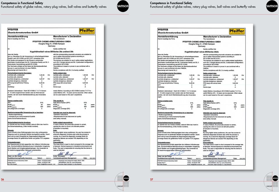
12 7 Applicable device documentation Each control valve has a data sheet, mounting and operating instructions as well as a certificate of conformity in accordance with the European Pressure Equipment Directive (PED) 97/23/EC and, if applicable, an explosion protection certificate. These documents are available in various languages on the Internet at and 8 Appendix 1 Manufacturer s declarations Series 240 und 250 Globe Valves with Type 3271 and 3277 Pneumatic Actuators as listed in Volume 1 and 2 of the Control Valves for Industrial Processes catalog (valve manufacturer: SAMSON AG) Type LTR43 Butterfly Valve with actuator (valve manufacturer: Leusch GmbH Industriearmaturen) Series 1a and 1b Globe Valves with Type 3271 and 3277 Pneumatic Actuators (valve manufacturer: Pfeiffer Chemie-Armaturen GmbH) Series 20a and 20b Ball Valves with Series 31a Actuator as listed in the Rotary Valves for Industrial Processes catalog (valve manufacturer: Pfeiffer Chemie-Armaturen GmbH) Series BR 26d Ball Valve with Series 31a Actuator as listed in the Rotary Valves for Industrial Processes catalog (valve manufacturer: Pfeiffer Chemie-Armaturen GmbH) Series 14b and 14c Butterfly Valves with Series 31a or 30 Actuators as listed in the Rotary Valves for Industrial Processes catalog (valve manufacturer: Pfeiffer Chemie-Armaturen GmbH) Series 72 and 73 Rotary Plug Valves with Type AT, R and M Pneumatic Actuators as listed in the Rotary Valves for Industrial Processes catalog (valve manufacturer: VETEC Ventiltechnik GmbH) 22 23

13

14
15

16 9 Appendix 2 Example of a checklist for a final element Checklist for testing safety equipment Checklist for testing safety equipment Final element test Yes No Is the tag documentation complete and up-to-date? Are the connecting cables in good order? Are the screw fittings in good order? Is the labeling complete and in a readable state? Control room, on site, process control system and safety PLC Are all connecting housings free of moisture, water, oil and dust? (solenoid valve, feedback etc.) Are the actuator or solenoid valve free of corrosion? Paint finish in good order? Visual inspection of the pneumatic system: Are all pneumatic connections in good order and leak-tight? Are the bridges, yokes, stem connectors, fastening nuts free of corrosion and fastened properly? Is the valve packing leak-tight? Are there any visible signs of the process medium? Is the bellows seal/bellows monitoring still in good order? Check of the exhaust ports of the solenoid valve Fail-safe position check Open final element in process control system Set to Manual and move P&ID Fail Close DCS * Valve: Remove air hose at the air manifold Loop Valve while the valve is being moved! Do the valve position and output signal match? Move valve to OPEN and CLOSED positions! Does the actuator move smoothly to its operating position when the signal pressure is applied? Is there any leakage at the actuator? Does the actuator move smoothly to its fail-safe position when moved by the springs? Valve transit time N/A Time to open the valve sec. Time to close the valve sec. Closing time Fail-close position Permissible leakage rate N/A N/A Time allowed for the valve to move to its fail-safe position Leakage rate allowed in fail-safe position sec. 1/min, m³/min Valve closing time to fail-safe position Leakage rate measured in fail-safe position sec. 1/min, m³/min To measure the leakage rate, the valve must be removed from the pipeline and tested in the workshop. Refer to DIN EN (A.4 Seat tightness) for the test procedures. The following table contains the permissible leakage rates. For control valves functioning as safety equipment, leakage can also be measured according to DIN EN Test medium Leakage rate A Leakage rate B Leakage rate C Leakage rate D Leakage rate E Leakage rate F Leakage rate G Liquid Liquid 0.01 *DN 0.03 *DN 0.1 *DN 0.3 *DN 1.0 *DN 2.0 *DN Gas No visible leaks found during test 0.3 *DN 3.0 *DN 30.0 *DN 300 *DN 3000 *DN 6000 *DN The leakage rates only apply when room temperature prevails at the outlet side. No visible leaks found during test means no visible moisture or formation of drops or bubbles. This corresponds to a lower leakage rate than leakage rate B. Attach green label after the test has been completed. Does repair work need to be performed on the system? If this is the case, write out a separate order. Tester 1: Tester 2: Test date: Signature: Owner Created/Revised by: Operation: Plant: Subplant: Tag no.: Operating state during test: PLC/DCS: Tester: Test date: Prüfung: Shutdown Fail-safe position: SIL level: Architecture: Measuring principle: Manufacturer: Manufacturer model: Body number/serial number/stamp number/id: Site of installation: Barrier medium: +H551-14E2 Final element exists in the following SIL loops SIF no.: Commissioning test: Proof test: Revision test: Final element test. years Lockout test - An assessment of the process and safety hazards in the plant and installation is necessary. - Obtain a permit to work! - Wear suitable protection for the work! Observe explosion protection regulations!. years - The person performing the work is responsible for using the appropriate maintenance methods according to the recognized codes of practice as well as for using suitable and tested tools! - The person performing the work bears the compulsory insurance during the work! This includes, for example, the safeguarding of the workplace against unauthorized access or against accidental contact with unprotected electrical installations while temporarily leaving the workplace. - Take precautionary measures to protect the plant against external influences, such as weather or other damaging environmental influences. Measuring equipment list: Type/Manufacturer/model: Serial number: Type/Manufacturer/model: Serial number: Type/Manufacturer/model: Serial number: Type/Manufacturer/model: Serial number: Type/Manufacturer/model: Serial number: Type/Manufacturer/model: Serial number: Tester 1: Tester 2: Test date: Signature: 30 31
 Are the actuator or solenoid valve free of corrosion? Paint finish in good order? Visual inspection of the pneumatic system: Are all pneumatic connections in good order and leak-tight?")
17 Local customer assistance across the world SAMSON AG MESS- UND REGELTECHNIK Weismüllerstraße Frankfurt am Main Germany Phone: Fax: samson@samson.de Internet: SAMSON GROUP HD WA 236 EN

Type 3244-1 and Type 3244-7 Pneumatic Control Valves. Type 3244 1 (left) and Type 3244-7 (right) Mounting and Operating Instructions EB 8026 EN
 and Type 3244-7 (right) Mounting and Operating Instructions EB 8026 EN") Type 3244-1 and Type 3244-7 Pneumatic Control Valves Type 3244 1 (left) and Type 3244-7 (right) Mounting and Operating Instructions E 8026 EN Edition July 2014 Definition of signal words DNGER! Hazardous
Type 3244-1 and Type 3244-7 Pneumatic Control Valves Type 3244 1 (left) and Type 3244-7 (right) Mounting and Operating Instructions E 8026 EN Edition July 2014 Definition of signal words DNGER! Hazardous
Type 3510-1 and Type 3510-7 Pneumatic Control Valves Type 3510 Micro-flow Valve
 Type 3510-1 and Type 3510-7 Pneumatic Control Valves Type 3510 Micro-flow Valve ANSI version Application Control valve especially designed for controlling low flow rates in pilot plants and technical research
Type 3353 Angle Seat Valve
 Type 3353 Angle Seat Valve Application On/off valve with pneumatic piston actuator Nominal size DN 15 to 50 (NPS ½ to 2) Nominal pressure PN Temperature range 10 to 180 C Globe valve with an angle seat
Pneumatic Shut-off Butterfly Valve Type 3335/31a SRP or DAP
 Pneumatic Shut-off Butterfly Valve Type 3335/31a SRP or DAP Application Tight-closing butterfly valve for process engineering and industrial applications DN 50 to 300 NPS 2 to 12 Nominal pressure PN 10
Pneumatic Control and Shut-off Butterfly Valve Pfeiffer Type BR 14b/31a and Type BR 14c/31a
 Pneumatic Control and Shut-off Butterfly Valve Pfeiffer Type BR 14b/31a and Type BR 14c/31a Application Tight-closing, double eccentric butterfly valve for process engineering and plants with industrial
Series 240 Type 3244-1 and Type 3244-7 Pneumatic Control Valves Type 3244 Three-way Valve
 Series 240 Type 3244-1 and Type 3244-7 Pneumatic Control Valves Type 3244 Three-way Valve DIN and ANSI versions Application Mixing or diverting valve for process engineering and industrial applications
SIL in de praktijk (Functional Safety) 23.04.2015 - Antwerpen. 61508 Compliance of Actuators and Life Cycle Considerations. SAMSON AG Dr.
 23.04.2015 - Antwerpen. 61508 Compliance of Actuators and Life Cycle Considerations. SAMSON AG Dr.") SIL in de praktijk (Functional Safety) 23.04.2015 - Antwerpen SAMSON AG Dr. Thomas Karte 61508 Compliance of Actuators and Life Cycle Considerations 2015-04-23 SAMSON AG Dr. Karte - 61508 Compliance of
SIL in de praktijk (Functional Safety) 23.04.2015 - Antwerpen SAMSON AG Dr. Thomas Karte 61508 Compliance of Actuators and Life Cycle Considerations 2015-04-23 SAMSON AG Dr. Karte - 61508 Compliance of
SAFETY MANUAL SIL Switch Amplifier
 PROCESS AUTOMATION SAFETY MANUAL SIL Switch Amplifier KCD2-SR-(Ex)*(.LB)(.SP), HiC282* ISO9001 2 With regard to the supply of products, the current issue of the following document is applicable: The General
System 6000 Electropneumatic Converter for Direct Current Signals Type 6116 i/p Converter
 System 6000 Electropneumatic Converter for Direct Current Signals Type 6116 i/p Converter Application Used to convert a direct-current input signal into a pneumatic output signal for measuring and control
SAFETY MANUAL SIL RELAY MODULE
 PROCESS AUTOMATION SAFETY MANUAL SIL RELAY MODULE KFD0-RSH-1.4S.PS2 ISO9001 3 With regard to the supply of products, the current issue of the following document is applicable: The General Terms of Delivery
Self-operated Pressure Regulators Universal Pressure Reducing Valve Type 41-23
 Self-operated Pressure Regulators Universal Pressure Reducing Valve Type 41-23 Application Pressure regulators for set points from 5 mbar to 28 bar Valves in nominal sizes DN 15 to 100 Nominal pressures
SAFETY LIFE-CYCLE HOW TO IMPLEMENT A
 AS SEEN IN THE SUMMER 2007 ISSUE OF... HOW TO IMPLEMENT A SAFETY LIFE-CYCLE A SAFER PLANT, DECREASED ENGINEERING, OPERATION AND MAINTENANCE COSTS, AND INCREASED PROCESS UP-TIME ARE ALL ACHIEVABLE WITH
FMEDA and Proven-in-use Assessment. Pepperl+Fuchs GmbH Mannheim Germany
 FMEDA and Proven-in-use Assessment Project: Inductive NAMUR sensors Customer: Pepperl+Fuchs GmbH Mannheim Germany Contract No.: P+F 03/11-10 Report No.: P+F 03/11-10 R015 Version V1, Revision R1.1, July
Self-operated Temperature Regulators Temperature Regulator Type 1u
 Self-operated Temperature Regulators Temperature Regulator Type u Application Temperature regulators for cooling installations Control thermostats for set points ) from 0 to 250 C G ½ to G or DN 5 to 50
Self-operated Temperature Regulators Type 1 to Type 9. PN 16 to 40 Class 125 to 300 DN 15 to 250 NPS ½ to 10 G ½ to 1 Up to 350 C Up to 660 F
 Self-operated Temperature Regulators Type 1 to Type 9 PN 16 to 40 Class 125 to 300 DN 15 to 250 NPS ½ to 10 G ½ to 1 Up to 350 C Up to 660 F Edition April 2012 Information Sheet T 2010 EN Self-operated
SAFETY MANUAL SIL SMART Transmitter Power Supply
 PROCESS AUTOMATION SAFETY MANUAL SIL SMART Transmitter Power Supply KFD2-STC4-(Ex)*, KFD2-STV4-(Ex)*, KFD2-CR4-(Ex)* ISO9001 2 3 With regard to the supply of products, the current issue of the following
Safety manual for Fisherr ED,ES,ET,EZ, HP, or HPA Valves with 657 / 667 Actuator
 Instruction Manual Supplement ED, ES, ET, EZ, HP, HPA Valves with 657/667 Actuator Safety manual for Fisherr ED,ES,ET,EZ, HP, or HPA Valves with 657 / 667 Actuator Purpose This safety manual provides information
Basic Fundamentals Of Safety Instrumented Systems
 September 2005 DVC6000 SIS Training Course 1 Basic Fundamentals Of Safety Instrumented Systems Overview Definitions of basic terms Basics of safety and layers of protection Basics of Safety Instrumented
Ball valve C 16 valve ball completely moulded in place, extremely low clearance volume, high k v value
 Ball valve C valve ball completely moulded in place, extremely low clearance volume, high k v value Advantage maximum safety due to valve ball completely moulded in place - ball and ball seat cannot be
Failure Modes, Effects and Diagnostic Analysis
 Failure Modes, Effects and Diagnostic Analysis Project: Plant-STOP 9475 Company: R. STAHL Schaltgeräte GmbH Waldenburg Germany Contract No.: STAHL 13/04-027 Report No.: STAHL 13/04-027 R024 Version V1,
OPERATING and MAINTENANCE MANUAL SERIES 2700A CONTROL VALVE CONTENTS. INTRODUCTION...1 Scope...1 Description...1 Valve Identification...
 OPERATING and MAINTENANCE MANUAL SERIES 2700A CONTROL VALVE CONTENTS INTRODUCTION...1 Scope...1 Description...1 Valve Identification...2 1.0 VALVE INSTALLATION...2 2.0 VALVE MAINTENANCE...3 Actuator Disassembly...3
Safety Requirements Specification Guideline
 Safety Requirements Specification Comments on this report are gratefully received by Johan Hedberg at SP Swedish National Testing and Research Institute mailto:johan.hedberg@sp.se -1- Summary Safety Requirement
Solenoid Valve Type 3962
 Solenoid Valve Type 362 x d, x em or without explosion protection, for controlling pneumatic actuators General The Type 362 Solenoid Valve ensures a high level of operational reliability for controlling
Effective Compliance. Selecting Solenoid Valves for Safety Systems. A White Paper From ASCO Valve, Inc. by David Park and George Wahlers
 Effective Compliance with IEC 61508 When Selecting Solenoid Valves for Safety Systems by David Park and George Wahlers A White Paper From ASCO Valve, Inc. Introduction Regulatory modifications in 2010
Final Element Architecture Comparison
 Final Element Architecture Comparison 2oo2 with diagnostics: Lower False Trip Rate and High Safety Project: Safety Cycling Systems Architecture Review Customer: Safety Cycling Systems, L.L.C. 1018 Laurel
SAFETY MANUAL SIL SWITCH AMPLIFIER
 PROCESS AUTOMATION SAFETY MANUAL SIL SWITCH AMPLIFIER KF**-SR2-(Ex)*(.LB), KFD2-SR2-(Ex)2.2S ISO9001 2 With regard to the supply of products, the current issue of the following document is applicable:
ISORIA. Centered disc butterfly valves with AMRING elastomer liner. 240 PSI: 1½ to8. 150 PSI : 10 to 24
 Type series booklet 8448.1/2-EN--US ISORIA Centered disc butterfly valves with AMRING elastomer liner 240 PSI: 1½ to8 150 PSI : 10 to 24 Design in accordance with ISO 10631 Manual, electrical, pneumatical
Hardware safety integrity Guideline
 Hardware safety integrity Comments on this report are gratefully received by Johan Hedberg at SP Swedish National Testing and Research Institute mailto:johan.hedberg@sp.se Quoting of this report is allowed
Solenoid Valve Island Type 3965
 Solenoid Valve Island Type 365 for the control of pneumatic actuators General The Type 365 Solenoid Valve Island is a compact solution for the centralized control of pneumatic actuators in chemical and
Diaphragm Actuators Favorable Variety Pneumatic Diaphragm Actuators Electric Actuators Hydraulic Actuators
 Favorable Variety Whether rotary or linear with pneumatic, electric, and hydraulic valve actuators from ARCA Regler GmbH, you always have the right solution at hand. ARCA s comprehensive product portfolio
SELECTION, APPLICATION AND MAINTENANCE
 DIESEL PROTECTION SYSTEMS Automatic Diesel Engine Shut Down System for Safe Area Applications SELECTION, APPLICATION AND MAINTENANCE Series 300 Series 310 SYSTEM DESCRIPTION Suitable for attended engine
FUNCTIONAL SAFETY CERTIFICATE
 FUNCTIONAL SAFETY CERTIFICATE This is to certify that the hardware safety integrity of the Valvetop ESD Valve Controller manufactured by TopWorx Inc. 3300 Fern Valley Road Louisville Kentucky 40213 USA
Automation System TROVIS 6400 TROVIS 6493 Compact Controller
 Automation System TROVIS 6400 TROVIS 6493 Compact Controller For panel mounting (front frame 48 x 96 mm/1.89 x 3.78 inch) Application Digital controller to automate industrial and process plants for general
Inductive sensor NI10-M18-Y1X-H1141
 ATEX category II 1 G, Ex zone 0 ATEX category II 1 D, Ex zone 20 SIL2 as per IEC 61508 Threaded barrel, M18 x 1 Chrome-plated brass DC 2-wire, nom. 8.2 VDC Output acc. to DIN EN 60947-5-6 (NA- MUR) M12
Instruction Manual Differential Pressure Transmitter
 DE28 Instruction Manual Differential Pressure Transmitter Table of Contents 1. Safety Instructions 2. Intended Applications 3. Product Description and Functions 4. Installation 5. Commissioning 6. Maintenance
Technical Data. Dimensions
 0102 Model Number Features 15 mm quasi flush Usable up to SIL2 acc. to IEC 61508 Accessories BF 30 Mounting flange, 30 mm V1-G-N-2M-PUR Female cordset, M12, 2-pin, NAMUR, PUR cable V1-W-N-2M-PUR Female
PBX Series Quick Fit Connector Bimetallic Steam Traps
 6262100/6 IM-P626-01 ST Issue 6 PBX Series Quick Fit Connector Bimetallic Steam Traps Installation and Maintenance Instructions 1. Safety information 2. General product information 3. Installation 4. Commissioning
Elektromotoren und Gerätebau Barleben GmbH
 Elektromotoren und Gerätebau Barleben GmbH OPERATING INSTRUCTIONS Transformer Protection Relay (Buchholz principle) Elektromotoren und Gerätebau Barleben GmbH Table of contents Page 1 Safety instructions
Control- and feedback head for integrated mounting on Robolux valves Type 2036
 Control- and feedback head for integrated mounting on Robolux valves Type 203 Type 885 Type 88 can be combined with Compact stainless steel design Contactless valve position registration Coloured illuminated
Guidelines. Safety Integrity Level - SIL - Valves and valve actuators. March 2009. Valves
 Valves Guidelines Safety Integrity Level - SIL - Valves and valve actuators March 2009 VDMA German Engineering Federation Valves Manufacturers Association Chairman: Prof.-Dr.-Ing. Heinfried Hoffmann Managing
Magnetic field sensor for pneumatic cylinders BIM-INT-Y1X-H1141
 ATEX category II 1 G, Ex zone 0 ATEX category II 1 D, Ex zone 20 SIL2 as per IEC 61508 Rectangular, height 6mm Plastic, PA12 Magnetic-inductive sensor DC 2-wire, nom. 8.2 VDC Output acc. to DIN EN 60947-5-6
4/2-Way Pneumatic Solenoid Valve
 4/2-Way Pneumatic Solenoid Valve Robust servo assisted piston valve Service friendly manual override Single or block assembly Explosion-proof versions Type 5413 cam be combined with Type 2508 Cable plug
Selecting Sensors for Safety Instrumented Systems per IEC 61511 (ISA 84.00.01 2004)
") Selecting Sensors for Safety Instrumented Systems per IEC 61511 (ISA 84.00.01 2004) Dale Perry Worldwide Pressure Marketing Manager Emerson Process Management Rosemount Division Chanhassen, MN 55317 USA
Selecting Sensors for Safety Instrumented Systems per IEC 61511 (ISA 84.00.01 2004) Dale Perry Worldwide Pressure Marketing Manager Emerson Process Management Rosemount Division Chanhassen, MN 55317 USA
Digital inductive conductivity transmitter
 Digital inductive conductivity transmitter Optimal solution for conductivity measurements in difficult fluids (polluted, dirty,...) PEEK/PPA version for CIP applications Large range of process connections
VdS 2100-09en. VdS Guidelines for water extinguishing systems. Non-return valves. Requirements and test methods. VdS 2100-09en : 2011-05 (01)
") VdS Guidelines for water extinguishing systems VdS 2100-09en Requirements and test methods VdS 2100-09en : 2011-05 (01) Publishing house: VdS Schadenverhütung GmbH Amsterdamer Str. 172-174 50735 Köln,
VdS Guidelines for water extinguishing systems VdS 2100-09en Requirements and test methods VdS 2100-09en : 2011-05 (01) Publishing house: VdS Schadenverhütung GmbH Amsterdamer Str. 172-174 50735 Köln,
Combi switchbox with integrated 3/2 way pilot valve
 H Combi switchbox with integrated 3/2 way pilot valve Construction The GEMÜ combi switchbox with integrated 3/2 way pilot valve for pneumatically operated quarter turn actuators has a micro-processor controlled
97300 NAMUR series, 3/2 & 5/2 Indirect solenoid actuated spool valve
 9700 NAMUR series, / & / > > Port size: G/, / NPT, NAMUR Interface > > Crossover-free switching > > Main application: Single and double acting actuators > > / way valve usable as / way valve > > Manual
www.klmtechgroup.com TABLE OF CONTENT
 Page : 1 of 31 Project Engineering Standard www.klmtechgroup.com KLM Technology #03-12 Block Aronia, Jalan Sri Perkasa 2 Taman Tampoi Utama 81200 Johor Bahru Malaysia TABLE OF CONTENT SCOPE 2 REFERENCES
Instructions Manual. Electromagnetic sensor Series FLOMID FX. instrumentation for fluids. R-MI-FlomidFX Rev.: 0 English version
 instrumentation for fluids Electromagnetic sensor Series FLOMID FX Instructions Manual! Conforms with the Pressure Equipment Directive 97/23/EC. 0830 This equipment is considered as being a pressure accessory
Technical Data. Dimensions
 0102 Model Number Features Comfort series 5 mm flush Usable up to SIL 2 acc. to IEC 61508 Accessories BF 18 Mounting flange, 18 mm EXG-18 Quick mounting bracket with dead stop Technical Data specifications
S GATE KNIFE GATE VALVE WITH PNEUMATIC ACTUATOR
 MAIN FEATURES The pneumatic S GATE knife gate valve is intended for the automatic shut off of pipes of the heavy fluids like slurries and powders. The main fields of application are the water treatment,
SunMaxx Solar Filling Station Operating Instructions
 SunMaxx Solar Filling Operating Instructions Content 1. Declaration of conformity... 2 2. Introduction... 2 3. Transportation and unpacking... 4 4. Mounting and commissioning... 5 5. End of operation...
Elektromotoren und Gerätebau Barleben GmbH
 Elektromotoren und Gerätebau Barleben GmbH OPERATING INSTRUCTIONS Transformer Protection Relay NM Series (Buchholz principle) Elektromotoren und Gerätebau Barleben GmbH Table of contents Page 1. Safety
A descriptive definition of valve actuators
 A descriptive definition of valve actuators Abstract A valve actuator is any device that utilizes a source of power to operate a valve. This source of power can be a human being working a manual gearbox
3/2-, 5/2- and 5/3-way Solenoid Valves for process pneumatics
 3/2-, 5/2-5/3-way Solenoid Valves for process pneumatics Type 6518 stard High flow-rate capacity Reduced power consumption Single or manifold mounting stard Type 6518/6519 can be combined with... Stard-,
SISTO-16TWA/HWA/DLU. Type Series Booklet
 Diaphragm Valve SISTO-16TWA/HWA/DLU PN16 DN 15-200 Maintenance-free Flanged Ends Type Series Booklet Legal information/copyright Type Series Booklet SISTO-16TWA/HWA/DLU All rights reserved. The contents
M A N U A L 13-10-05
 Documentation The following information sheets illustrate the description below: 12-WW01-4G-E Sectional view of the lance with main dimensions 12-W101-6G-E Sectional view of the head of the lance with
Guidelines for operation of minimum flow control valves
 Guidelines for operation of minimum flow control valves Holter Regelarmaturen GmbH & Co KG Helleforthstr. 58-60 D-33758 Schloß Holte-Stukenbrock 05/2005 List of contents I. Minimum flow control valves...
How To Control A Power Supply With A Mini Transmitter And Switch (Power Supply)
") transmitter (2 wire) / switch for continuous or On/Off Control Indication, monitoring, transmitting and continuous or On/Off control in one device Output signal 4...20 ma, 2-wire for continuous control
transmitter (2 wire) / switch for continuous or On/Off Control Indication, monitoring, transmitting and continuous or On/Off control in one device Output signal 4...20 ma, 2-wire for continuous control
Understanding Safety Integrity Levels (SIL) and its Effects for Field Instruments
 and its Effects for Field Instruments") Understanding Safety Integrity Levels (SIL) and its Effects for Field Instruments Introduction The Industrial process industry is experiencing a dynamic growth in Functional Process Safety applications.
Understanding Safety Integrity Levels (SIL) and its Effects for Field Instruments Introduction The Industrial process industry is experiencing a dynamic growth in Functional Process Safety applications.
FlowPak TM General Application Valve 1/2-4, Class 150
 FlowPak TM General Application Valve 1/2-4, Class 150 SCHERR Application Control of gases, vapours and liquids. The modular concept of valve, multi spring actuator and digital Positioner Type Logix 5si,
Version: 1.0 Latest Edition: 2006-08-24. Guideline
 Management of Comments on this report are gratefully received by Johan Hedberg at SP Swedish National Testing and Research Institute mailto:johan.hedberg@sp.se Quoting of this report is allowed but please
Unit 24: Applications of Pneumatics and Hydraulics
 Unit 24: Applications of Pneumatics and Hydraulics Unit code: J/601/1496 QCF level: 4 Credit value: 15 OUTCOME 2 TUTORIAL 4 DIRECTIONAL CONTROL VALVES The material needed for outcome 2 is very extensive
ABB Drives. User s Manual. Pulse Encoder Interface Module RTAC-01
 ABB Drives User s Manual Pulse Encoder Interface Module RTAC-0 Pulse Encoder Interface Module RTAC-0 User s Manual 3AFE 64486853 REV A EN EFFECTIVE:.5.00 00 ABB Oy. All Rights Reserved. Safety instructions
Technical Data. General specifications Switching element function Rated operating distance s n 5 mm
 0102 Model Number Features 5 mm flush Usable up to SIL 2 acc. to IEC 61508 Accessories EXG-18 Quick mounting bracket with dead stop BF 18 Mounting flange, 18 mm Technical Data specifications Switching
Series 3730 Type 3730-2 Electropneumatic Positioner
 Series 3730 Type 3730-2 Electropneumatic Positioner Application Single-acting or double-acting positioner for attachment to pneumatic control valves. Self-calibrating, automatic adaptation to valve and
Technical Data. General specifications Switching element function Rated operating distance s n 4 mm
 0102 Model Number Features 4 mm non-flush Usable up to SIL 3 acc. to IEC 61508 Application Danger! In safety-related applications the sensor must be operated with a qualified fail safe interface from Pepperl+Fuchs,
Valve series MN-06 acc. to NAMUR, 3/2-way G1/4 750 Nl/min (0.762 Cv)
") Valve series MN-06 acc. to NAMUR, 3/2-way G1/4 750 Nl/min (0.762 Cv) Order code Series and function 1) Plug socket see page 5.042. MN-06-310-HN-442 Standard coil 1) 441 = 12 V DC, 4.2 W 442 = 24 V DC,
Valve series MN-06 acc. to NAMUR, 3/2-way G1/4 750 Nl/min (0.762 Cv) Order code Series and function 1) Plug socket see page 5.042. MN-06-310-HN-442 Standard coil 1) 441 = 12 V DC, 4.2 W 442 = 24 V DC,
% ^ ) 0.55 W Low Power Solenoid Valves Aluminum, Brass, or Stainless Steel Bodies 1/4" to 1" NPT. 2/2 3/2 4/2 5/2 5/3 SERIES Low Power
 0.55 W Low Power Solenoid Valves Aluminum, Brass, or Stainless Steel Bodies 1/4 to 1 NPT. 2/2 3/2 4/2 5/2 5/3 SERIES Low Power") .55 W Solenoid Valves Aluminum, Brass, or Stainless Steel Bodies /" to " NPT / 3/ / 5/ 5/3 Features Molded one-piece solenoid with highly efficient solenoid cartridge and.55 W low wattage coil Standard
.55 W Solenoid Valves Aluminum, Brass, or Stainless Steel Bodies /" to " NPT / 3/ / 5/ 5/3 Features Molded one-piece solenoid with highly efficient solenoid cartridge and.55 W low wattage coil Standard
IEC 61508 Functional Safety Assessment. ASCO Numatics Scherpenzeel, The Netherlands
 IEC 61508 Functional Safety Assessment Project: Series 327 Solenoid Valves Customer: ASCO Numatics Scherpenzeel, The Netherlands Contract No.: Q09/04-59 Report No.: ASC 09-04-59 R003 V1 R3 61508 Assessment
Technical Data. General specifications Switching element function Rated operating distance s n 15 mm
 0102 Model Number Features Comfort series 15 mm flush Accessories MHW 01 Modular mounting bracket MH 04-2057B Mounting aid for VariKont and +U1+ Technical Data General specifications Switching element
Fisher 1052 Size 20 Diaphragm Rotary Actuator with F and G Mounting Adaptation
 Instruction Manual 1052 Size 20 Actuator (F & G) Fisher 1052 Size 20 Diaphragm Rotary Actuator with F and G Mounting Adaptation Contents Introduction... 1 Scope of manual... 1 Description... 1 Specifications...
MXa SIL Guidance and Certification
 MXa SIL Guidance and Certification SIL 3 capable for critical applications Experience In Motion Functional Safety in Plants Safety and instrumentation engineers demand that a functional safety system s
DXPE*J 85 320/215 ED. DIRECtIONAL CONtROL VALVE PILOt OPERAtED, WItH OBE AND FEEDBACK. Q max (see performance table) SERIES 30
 SERIES 30") 85 320/215 ED DXPE*J DIRECtIONAL CONtROL VALVE PILOt OPERAtED, WItH OBE AND FEEDBACK SUBPLAtE MOUNtINg DXPE5J CEtOP P05 DXPE5RJ ISO 4401-05 (CETOP R05) DXPE7J ISO 4401-07 (CETOP 07) DXPE8J ISO 4401-08
85 320/215 ED DXPE*J DIRECtIONAL CONtROL VALVE PILOt OPERAtED, WItH OBE AND FEEDBACK SUBPLAtE MOUNtINg DXPE5J CEtOP P05 DXPE5RJ ISO 4401-05 (CETOP R05) DXPE7J ISO 4401-07 (CETOP 07) DXPE8J ISO 4401-08
Spira-trol TM Two-port Control Valves EN Standard KE, KF and KL DN15 to DN300 and ASME Standard KEA, KFA and KLA ½" to 12"
 Local regulations may restrict the use of this product to below the conditions quoted. In the interests of development and improvement of the product, we reserve the right to change the specification without
A methodology For the achievement of Target SIL
 A methodology For the achievement of Target SIL Contents 1.0 Methodology... 3 1.1 SIL Achievement - A Definition... 4 1.2 Responsibilities... 6 1.3 Identification of Hazards and SIL Determination... 8
Richter Twin Piston Quarter-turn Actuators
 Richter Twin Piston Quarter-turn ctuators R ompact Powerful Maintenance-free R ouble-acting quarter-turn actuators The actuators are the optimum automation units in technical and commercial terms for Richter
Proportional pressure regulators VPPE
 Proportional pressure regulators VPPE Proportional pressure regulators VPPE Product range overview Function Version Pneumatic connection Proportional pressure regulator Nominal size for pressurisation/
Power Supply and Indicator Unit Type 5024-1. Fig. 1 Type 5024-1. Mounting and Operating Instructions EB 9539 EN
 Power Supply and Indicator Unit Type 5024-1 Fig. 1 Type 5024-1 Mounting and Operating Instructions EB 9539 EN Edition October 2003 Application 1 Application The Type 5024-1 Power Supply and Indicator Unit
Series 3730 Type 3730-5 Electropneumatic Positioner with FOUNDATION fieldbus communication
 Series 3730 Type 3730-5 Electropneumatic Positioner with FOUNDATION fieldbus communication Application Positioners for attachment to pneumatic control valves Valve travel from 3.6 to 300 mm Opening angle
Order Code for GEA Tuchenhagen VESTA Sterile Valves. Type H_A 2/2 Way Seat Valve
 Order Code for VESTA Sterile Valves Type H_A 2/2 Way Seat Valve engineering for a better world GEA Mechanical Equipment VESTA Sterile Valves are designed for universal use in sterile process technology.
2- and 3-port valves with flanged connections, PN 10
 4 402 VVF32.. VXF32.. ACVATIX 2 and 3port valves with flanged connections, PN 10 From the largestroke valve line VVF32.. VXF32.. Performance valves for medium temperatures from 10 150 C Valve body of grey
Type overview. Technical data
 Technical data sheet R3..xx-S.. Characterised control valve, 3-way, Internal thread For closed cold and warm water systems For modulating water-side control of air handling units and heating systems ir
Packing and gaskets Page 029 of 040
 Packing and gaskets Page 029 of 040 7.3 Packing and gaskets The chemical industry has carried out cadastral surveys for many years. These surveys provide valuable information regarding environmental pollution
Mounting Instructions. Torque Transducer. A0329 3.2 en
 Mounting Instructions Torque Transducer T5 T5 Contents 3 Page Safety instructions.............................................. 4 1 Measuring characteristics..................................... 7 2 Mounting.....................................................
Pressure regulating valve with modulating kit, type DRV
 Operation Installation and Maintenance Instructions Pressure regulating valve with modulating kit, type DRV hp-technik GmbH Industriepumpen-Förderaggregate und Anlagenbau Gablonzer Straße 21 D-76185 Karlsruhe
E4E PILOT OPERATED DIRECTIONAL CONTROL VALVE WITH ELECTRIC PROPORTIONAL CONTROL SERIES 51
 83 300/100 ED E4E PILOT OPERATED DIRECTIONAL CONTROL VALVE WITH ELECTRIC PROPORTIONAL CONTROL SUBPLATE MOUNTING CETOP P05 p max 250 bar Q max (see specification table) MOUNTING INTERFACE OPERATING PRINCIPLE
Electric Rotary Actuator - On/Off or programmable control actuator
 Electric Rotary Actuator - On/Off or programmable control actuator Direct mounting on quarter-turn valves Manual override standard Corrosion resistant Adjustable limit switches Multi-voltage version Type
ABB i-bus EIB / KNX Analogue Input AE/S 4.2
 Product Manual ABB i-bus EIB / KNX Analogue Input AE/S 4.2 Intelligent Installation Systems This manual describes the functionality of Analogue Input AE/S 4.2. Subject to changes and errors excepted. Exclusion
SITEMA PowerStroke. Technical Information TI-P11. 1 Function. 2 Applications. Mould Closing Devices series FSK. Contents
 English translation of German original Technical Information TI-P11 SITEMA PowerStroke Mould Closing Devices series FS drive system for powerful forces on a short stroke hydraulic actuation closing force
Proportional relief valves type AGMZO-TERS, AERS two stage, with integral or remote pressure transducer, ISO 6264 size 10, 20 and 32
 www.atos.com Table F040-1/E Proportional relief valves type AGMZO-TERS, AERS two stage, with integral or remote pressure transducer, ISO 6264 size 10, 20 and 32 AGMZO are two stage poppet type proportional
ABV20 Air Actuated Boiler Blowdown Valve Installation and Maintenance Instructions
 4057250/8 IM-P405-16 AB Issue 8 ABV20 Air Actuated Boiler Blowdown Valve Installation and Maintenance Instructions 1 General safety information 2 General product information 3 Installation 4 Operation
Terminology and Symbols in Control Engineering
 Technical Information Terminology and Symbols in Control Engineering 1 Part 1 Fundamentals Technical Information Part 1: Fundamentals Part 2: Self-operated Regulators Part 3: Control Valves Part 4: Communication
Pneumatic actuators The Original! Technics of the top class.
 Automatic valves Actuators Accessories Pneumatic actuators The Original! Technics of the top class. Leaflet no. S1-01e-13 Table of contents Advantages and your benefits...page 3 Figure: actuator...page
36G22, 36G23, 36G24 & 36G52 36J22, 36J23, 36J24 & 36J52 DSI and HSI Single Stage Combination Gas Valve
 Operator: Save these instructions for future use! FAILURE TO READ AND FOLLOW ALL INSTRUCTIONS CAREFULLY BEFORE INSTALLING OR OPERATING THIS CONTROL COULD CAUSE PERSONAL INJURY AND/OR PROPERTY DAMAGE. DESCRIPTION
How To Use A Flowmeter
 INLINE flowmeter for continuous flow measurement Economic integration in pipe systems without any additional piping 3-wire frequency pulse version to directly interface with PLC s (both PNP and NPN) Connection
kymanual or Automatic - it s your Choice
 . kymanual or Automatic - it s your Choice ky LKB Automatic or Manual Butterfly Valve Application LKB is a sanitary automatically or manually operated butterfly valve for use in stainless steel pipe systems.
Safety Manual BT50(T) Safety relay / Expansion relay
 Safety relay / Expansion relay") Safety Manual BT50(T) Safety relay / Expansion relay ABB Jokab Safety Varlabergsvägen 11, SE-434 39, Sweden www.abb.com/jokabsafety Read and understand this document Please read and understand this document
Safety Manual BT50(T) Safety relay / Expansion relay ABB Jokab Safety Varlabergsvägen 11, SE-434 39, Sweden www.abb.com/jokabsafety Read and understand this document Please read and understand this document
3/2, 5/2, 5/2 bistable and 5/3 way pneumatic solenoid valve
 3/2, 5/2, 5/2 bistable and 5/3 way pneumatic solenoid valve Type 6518 Type 6519 Type 6518/6519 can be combined with... Single or block mounting Suitable for outdoor and chemical atmospheres Suitable for
RUBBER SLEEVE KNIFE GATE VALVE
 RUBBER SLEEVE KNIFE GATE VALVE The model knife gate is a wafer valve designed for a wide range of industrial applications. The double-seated design provides bi-directional shut off. The design of the valve