USER MANUAL EXTROLLER
|
|
|
- Emil Cannon
- 7 years ago
- Views:
Transcription
1 COAIRE SCREW AIR COMPRESSORS USER MANUAL EXTROLLER SERIAL NO. : MODEL NO. : CAUTION For proper and safe use of the compressor, please follow all instructions and safety precautions as identified in this manual, along with general safety regulations and practices. Before installing and starting the compressor, read and understand this manual All rights reserved HSA-100S PART NO. CHSA-E07 DATE OF ISSUE: JANUARY, 2007 Printed in U.S.A.

2 CONTENT: 1.0 General Description Controller Model Variants General Operation I/O Description Digital Inputs Digital Outputs Analogue Inputs and Outputs Machine State Diagram User Interface Keypad Led Indicators Display Display Structure and Menu Navigation Menu Structure P00 User Menu P01 Operation Menu P02 Error Log Menu Fault Messages Immediate Stop Shutdown Errors Digital input errors Analogue input errors Special function errors Controlled Stop Shutdown Errors Alarms Digital input alarms Analogue input alarms Special function alarms Start Inhibits Run Inhibits Service Alarms Special function service alarms

3 1.0 General Description 1.1 Controller Model Variants The general default settings and tables shown in this specification are applicable to the standard production S1 controller model S1-20-3#0; functions available for alternative models can be set in configuration menus. # = 3 for KTY temperature sensor (or RTD optional) S1CMCSTD.E05+ # = 7 for PT1000 temperature sensor S1CMCPT1.E03+ Temperature detection and setting limits may differ on models fitted with, and set for, alternative temperature sensor ACM types: For example: S KTY or RTD temperature sensor, no internal pressure detection S PT100 temperature sensor, no internal pressure detection S PT1000 temperature sensor, no internal pressure detection S KTY or RTD temperature sensor, with internal pressure detection S PT100 temperature sensor, with internal pressure detection S PT1000 temperature sensor, with internal pressure detection S KTY or RTD temperature sensor, no internal pressure detection S PT100 temperature sensor, no internal pressure detection S PT1000 temperature sensor, no internal pressure detection S KTY or RTD temperature sensor, with internal pressure detection S PT100 temperature sensor, with internal pressure detection : Applied to Compressor. S PT1000 temperature sensor, with internal pressure detection The temperature sensor type must be set in the configuration menu if other than the type applicable to the software variant. All temperature sensor types are available in both software variants and are dependant on the type of ACM hardware fitted. S Extroller applied to compressor. Internal pressure detection, differential pressure detection and related functions will be unavailable on models that are not fitted with a secondary pressure sensor analogue input ACM. Internal pressure detection must be enabled in the configuration menu for model types fitted with the secondary pressure detection ACM hardware. Variable speed regulation is only available on S1-20 models. 3

4 1.2 General Operation In normal operation, the detected delivery pressure controls regulation of the compressor once the compressor has been started by pushing the start button, or by a remote start command if enabled. The controller will perform safety checks and start the compressor if no inhibiting conditions are detected. If a start inhibiting condition exists the compressor will not enter the started condition and a start inhibit message is displayed. If a run inhibiting condition exists the compressor will enter the started condition but a main motor start is inhibited; the compressor will remain in the standby condition and a run inhibit message is displayed. If a load request is present, in accordance with internal pressure settings or by remote command, the main motor is started in a star/delta sequence. When running in delta configuration, after the star/delta time (adjustable) has expired, the load delay time (adjustable) prevents loading for a period to allow motor speed to stabilize. The load delay time can be set to one second if required. When the load delay time has expired the load valve output is energized and the compressor will load. If the unload pressure setting is reached, or a remote unload command is received, the load valve output is de-energized and the compressor will run offload for the standby run on time (adjustable) before the main motor stops and the compressor enters Standby mode. The compressor will load again if pressure falls below the load setting before the standby run on time expires. If in Standby mode, a motor start sequence followed by the load delay time is executed before loading. In the event of a motor stop, initiated by a stop command or when entering standby mode, a blow down timer (adjustable) is started. If a start request is made during the blow down time the compressor will enter standby mode until the blow down time expires. If already in standby mode, and a load request is present, the compressor will remain in standby mode until the blow down time has expired. For units with internal pressure detection enabled, a minimum internal re-start pressure can also be set to prevent a motor start sequence before internal pressure is vented. In the event internal pressure fails to fall below the set minimum re-start pressure within two minutes after the set blow down time has expired, a blow down fault is generated and the compressor will shutdown. After an unload event a re-load timer (adjustable) is initiated that will prevent reloading, this time can be adjusted to a minimum of one second if required. Normal automated operation is ended by pushing the stop button, a remote stop command or in the event of a shutdown fault. When stopped manually, or by a remote command, the load value is de-energized and the main motor allowed to runon for the stop run on time (adjustable). This time can be adjusted to a minimum of one second if required. Safety checks are made continuously, if there is a condition detected that presents a hazardous or damaging situation an immediate stop is performed and the reason displayed as a shutdown error message. If a warning condition is detected an Alarm message is displayed and normal operation continues. 4

5 2.0 I/O Description 2.1 Digital Inputs Connector X04: Connector type: 9 pole mini Combicon with 3.81mm (0.15 ) pitch Pin name function id active state 1 C+ Digital inputs common 2 C1 Emergency Stop Digital input 1 Fault if open 3 C2 Oil Filter high DP Digital input 2 Fault if open 4 C3 Air Filter high DP Digital input 3 Not used 5 C4 Air / Oil Separator DP Digital input 4 Fault if open 6 C5 Remote start / stop Digital input 5 Stop if open / start on closure 7 C6 Remote Load enable Digital input 6 Remote if closed 8 C7 Remote Load Digital input 7 Load if closed / offload if open 9 C8 PTC motor overload Digital input 8 Fault if open Remote Stop: When the remote start/stop function is enabled (P07), the compressor will execute a controlled stop, as if the control panel stop button had been pressed, when the remote start/stop input is open circuit. Remote Start: When the remote start/stop function is enabled (P07), the compressor will execute a normal start sequence when the remote start/stop input changes state from open to closed circuit. If closed, the remote start/stop input must be opened and closed again to initiate a remote start sequence. Local controller start is inhibited. Remote load enable: When the digital remote load enable input is activated, local or communications pressure regulation is ignored and the unit will respond to the digital remote load input. The unit will automatically respond to the pressure regulation method set in the configuration menu settings (local or communications) when the digital remote load enable is deactivated. Remote load: When the digital remote load enable is activated, the unit will load when the digital remote load input is activated and unload when the digital remote load input is deactivated. All pressure safety settings remain active when using remote load functions. Note: If local detected delivery pressure exceeds the set Alarm level the load solenoid output is deenergized. The load solenoid output will remain de-energized for 10secs after the pressure falls below the Alarm level. 5

6 2.2 Digital Inputs Connector X03: relays Connector type: 6 pole mini Combicon with 5mm pitch Pin name function id active state 1 C-R123 Common for Star, Delta, and Main contactor 2 NO-R1 Main contactor Digital output 1 Energized 3 NO-R2 Star contactor Digital output 2 Energized 4 NO-R3 Delta contactor Digital output 3 Energized 5 C-R4 Common for load solenoid 6 R4 Load solenoid Digital output 4 Load when energized Connector X03: relays Connector type: 6 pole mini Combicon with 5mm pitch Pin name function id active state 1 C-R5 Common Relay 5 2 NO-R5 Normal open contact Relay 5 Digital output 5 3 C-R6 Common Relay 6 4 NO-R6 Normal open contact Relay 6 Digital output 6 The function of auxiliary relay 5 and 6 can be set in the configuration menu. (Default: R5-Drain R6-Running(for control box Fan)) 6

7 2.3 Analogue Inputs And Outputs Note : All analogue device inputs have open circuit, short circuit and out-of-range fault detection functions Connector X05: analogue inputs Connector type: 6 pole mini Combicon with 3.81mm (0.15 ) pitch Pin name function id type range 1 C-ANA1 Delivery pressure +V common 2 ANA1 Delivery pressure input Analogue input mA Adjustable 3 C-ANA2 Temperature 0V common 4 ANA2 Temperature input (menu setting + ACM type) Analogue input 2 KTY or PT100, PT1000 or RTD or or C-ANA3 Internal pressure +V common 6 ANA3 Internal pressure (option) Analogue input mA Analogue Input 1 : fixed 4-20mA type Analogue inputs 2 and 3 : The S1 uses plug-in analogue conditioning modules (ACM s) that allow different sensor and signal types to be accommodated; for a particular sensor type the correct ACM hardware must be fitted. Connector X06: analogue output Connector type: 2 pole mini Combicon with 5.08mm pitch Pin name function id type range 1 AGND 0V analogue ground 2 ANA-OUT1 4-20mA analogue output Analogue output mA Adjustable Analogue Output 1: Standard 4-20mA signal, function selectable Variable Speed Control Active 4-20mA signal for percentage motor speed; 0% = stopped, 100% = maximum set motor speed 7
 Analogue input 2 KTY or PT100, PT1000 or RTD -10 132 or -50 250 or -40 150 5 C-ANA3 Internal pressure +V common 6 ANA3 Internal pressure (option) Analogue input 3")
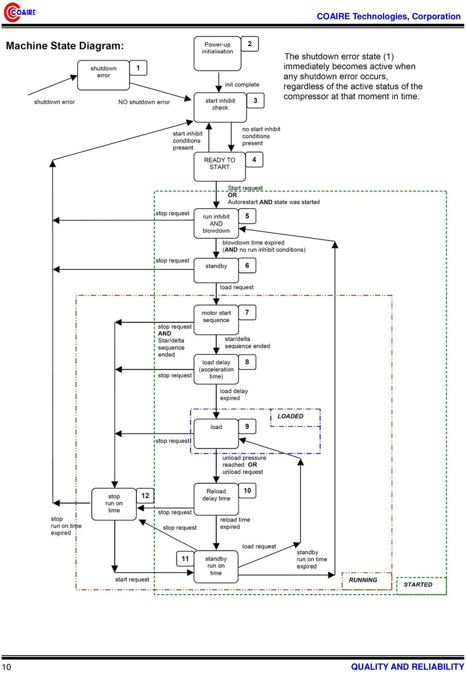
8 3.0 Machine State Diagram Controller operational logic is shown in the machine state diagram as state blocks with an associating status block number. The state block determines the functionality of the controller at any given time. The controller can only be in one state at any given time. The controller will move from state to state in accordance with the defined exit and entry conditions of each state block and the defined connections between state blocks. Definitions: Fault: A detected abnormal condition that must be indicated to operator personnel and that may require controller automated safety action, dependant on fault type and definition. Start Inhibit Fault (S): A start inhibit fault is a condition that may present a danger or cause damage to the compressor if started whilst the condition is present. Start inhibit faults are only triggered if a compressor start from the ready to start condition is attempted. Start inhibit faults are not triggered during an automated motor start sequence from the standby condition. Start inhibit faults are self-resetting. A start inhibit fault code is displayed when triggered but is not recorded in the fault log. Run Inhibit Fault (R): A run inhibit fault is a condition that may present a danger or cause damage to the compressor if the main motor is started whilst the condition is present. Run inhibit faults are only triggered if a motor start sequence is initiated. Run inhibit faults are self-resetting and do not prevent the compressor from entering a started condition. A Run inhibit will hold the compressor in a standby state and will allow a motor start sequence when the condition is no longer present. A Run inhibit fault code is displayed when triggered but is not recorded in the fault log. Alarm Fault (A): An alarm fault is a warning condition that does not present an immediate danger or potential damage to the compressor. An alarm state will not shutdown the compressor or affect normal operation. An alarm fault code is displayed that must be manually reset to clear once the condition has been resolved or no longer exists. Shutdown Fault (E): A shutdown fault is a condition that may present danger or potential damage to the compressor if the condition persists. A shutdown fault will cause the controller to stop the compressor. A shutdown fault code is displayed that must be manually reset to clear once the condition has been resolved or no longer exists. Two types of shutdown fault are definable a) non-emergency shutdown, an immediate controlled stop is executed, b) emergency shutdown, an instantaneous stop is executed. Unload Pressure: The unload pressure is the delivery pressure level (adjustable) at which the controller will de-energize the load solenoid output and the compressor will offload. Load Pressure: The load pressure is the delivery pressure level (adjustable) at which the compressor will energize the load solenoid output and the compressor will load. If in the standby state, an automated main motor start sequence is triggered prior to load. 8

9 Main Motor Start Sequence: The controller will energize the Star contactor output followed by the Main contactor output 200ms later. After the Star/Delta timer (adjustable) expires the controller will execute an automated Star to Delta contactor output changeover with a 50ms star to delta transition time. If a Stop command is received during the start sequence the controller will continue to execute the start sequence before stopping. This action is intended to limit the break current of motor starter contactors. Load Delay Timer: The star to delta output transition is immediately followed by a load delay time (adjustable) that will inhibit the load solenoid output from energizing until the load delay time expires. Intended to allow the main motor speed to stabilize and other pre-load functions to occur. Reload Delay Timer: The reload delay time (adjustable) is a period of time immediately following a load to unload event during which the load solenoid output is inhibited from energizing. Blow Down Timer: The blow down time (adjustable) immediately follows a main motor stop event. During the blow down time a start request is recognized but is not initiated until the timer expires. If the optional internal pressure detection feature is enabled the restart inhibit is also dependant on internal pressure falling below the start inhibit pressure level (adjustable). Failure of internal pressure to fall below the set pressure level for a period of two minutes after the set blow down timer expires will result in a blow down trip fault. The remaining time in seconds is show on the Information Item display. Standby Run-On-Time: When off load the standby run-on-timer will start. If the compressor remains in an off load condition and the timer expires the main motor will stop and the compressor will enter the Standby state. The compressor will automatically re-start and load as required. This function is intended to improve efficiency during low demand periods and to limit the number, and interval between, motor start events. The remaining time in seconds is show on the Information Item display. Stop Run-On-Time: When stopped (stop button, remote stop input or remote stop command) the compressor will unload and the main motor continue to run for the stop run-on-time before stopping. This function is intended to allow for internal pressure venting and to limit lubrication oil aeration prior to the main motor stopping. The remaining time in seconds is show on the Information Item display. Started State: The unit has been started (start button, remote start input or remote start command) and is in an active condition ready to respond to changes in delivery pressure. Running State: The unit is in the Started state AND the main motor is running. Loaded State: The unit is in the Started state AND Running state AND the load solenoid output is energized. 9

10 10
11 4.0 User Interface Display : Custom backlit LCD Indicators : 2 x LED Controls : 7 x Tactile push buttons 4.1 Keypad START: STOP: RESET: ENTER: MINUS/DOWN: PLUS/UP: ESCAPE (C): Enter STARTED condition Exit STARTED condition Reset and clear fault conditions Confirm selection or value adjustments Scroll down through menu, menu item options or decrement value Scroll up through menu, menu item options or increment value Step back one menu navigation level Start and Stop have one defined function and are not used for any other purpose. Reset will initiate a display jump to the fault code item if a fault condition remains active or initiate a display jump to the information item if no active faults exist in normal display mode. If pressed and held for longer than two seconds in menu mode will exit menu mode to the normal operational display mode, page 00. Enter will lock a selected value display preventing return, after a short delay, to the default Td value display. When locked the key symbol will flash. To unlock press Escape. Escape will initiate a display jump to the information item in normal display mode, page 00. Plus, Minus, Enter and Escape are used to navigate menu mode and adjust menu parameters. Keypad Symbol 11

12 Symbol Description START STOP RESET ENTER PLUS/UP MINUS/DOWN ESCAPE (C) Status Symbol Symbol Description Symbol Description High Temperature Alarm Overpressure Alarm Motor Overload Maintenance Alarm Motor Run Load Operation Lower Pressure Higher Pressure 12

13 4.2 Led Indicators STATUS: FAULT: Green, adjacent to Start and Stop buttons Red, adjacent to Stop and Reset buttons Indicator States: ON: Illuminated continuously. FF: Fast Flash: on/off four times per second. SF: Slow Flash: on/off once per second. IF: Intermittent Flash: on/off every four seconds. OFF: Extinguished continuously. Machine State Number Machine State Status Fault 1 Shutdown Error OFF FF 2 Startup Init OFF OFF** 3 Start Inhibit Check Start inhibit condition OFF OFF** SF 4 Ready to Start OFF OFF** 5 Blowdown if (load request) FF, else IF OFF** 6 Standby IF OFF** 7 Start Motor in Star / Delta if (load request) FF, else IF OFF** 8 Load Delay if (load request) FF, else IF OFF** 9 Load ON OFF** 10 Reload Delay if (load request) FF, else IF OFF** 11 Standby Run on Time IF OFF** 12 Stop Run on Time SF OFF** ** SF for Alarm condition 13
 FF, else IF OFF** 6 Standby IF OFF** 7 Start Motor in Star / Delta if (load request) FF, else IF OFF** 8 Load Delay if (load request) FF, else IF OFF** 9 Load ON OFF** 10 Reload Delay")
14 4.3 Display The display is divided in to 4 areas. Top, Left: Top, Right: Middle: Bottom: Display Field:- 4 character numeric display, with unit symbols, used to continuously show delivery pressure in normal operating mode or menu page number in menu mode Fault Symbol Field:- Symbolic displays used to indicate common general fault conditions Symbolic displays used to reinforce meaning of selected item, fault condition. Symbolic status information in normal operational mode Information Screen item Item and Value Field:- Item identification: 2 character alphanumeric, 14 segment Item Value: 4 character numeric, 7 segment Item Unit: 3 character alphanumeric, 14 segment 14 Segment Display Character Set: 7 Segment Display Character Set: 14

15 Display Character Examples, Units: Operational Display Symbols: Fault Display Symbols: 15

16 4.4 Display Structure and Menu Navigation Display Item Structure: All value, parameter or option selection displays are grouped into menu lists. Items are assigned to a list according to type and classification. Items that can be used to select options or modify functions are assigned to menu mode lists. Items that an operator may require to view during routine operation, detected pressure or temperature values for example, are assigned to the normal operational mode list. Lists are identified by page number, the normal operational display list is page 0. All parameters and options are assigned to menu mode pages 1 or higher. All Page 0 items are view only and cannot be adjusted. Normal Operational Mode (Page 0): At controller initialization, all display elements and LED indicators are switched on for three seconds, the display will then show the software version code for a further 3 seconds before initialization is complete and the normal operating display (Page 0) is shown. In page 0 normal operational display mode the Display Field will show the final delivery pressure continuously and the Item and Value Fields will initially show the Information Item display for 35 seconds before reverting to the default temperature display item. All available Item and Value field option displays (temperatures, pressures, hours counters) can be selected using the Up or Down buttons at any time. The Item display will revert to the default item after 35 seconds if no further selection is made. Pressing the Enter button will lock any selected Item display and inhibit return to the default display. When an Item display is locked the lock key symbol will slow flash. To unlock an Item display press Up or Down to view an alternative Item display or press Reset or Escape. In page 0 Escape will select the Status Information Item display and Reset will select any active fault code display or the Status Information Item display if no faults are active. Unless a selected Item display is locked, the display will automatically jump to the Status Information Item display at key status change events. The timeout period before returning to the default Item display is modified in some instances to enable the full range of a set countdown timer to be shown. No Item values, options or parameters can be adjusted in page 0. If a fault condition occurs the fault code becomes the first list item and the display will automatically jump to display the fault code. More than one active fault code item can exist at any one time. Access Code: Access to page list displays higher than page 0 are restricted by access code. To access menu mode pages press UP and DOWN together, an access code entry display is shown and the first code character will flash. Use PLUS or MINUS to adjust the value of the first code character then press ENTER. The next code character will flash; use UP or DOWN to adjust then press ENTER. Repeat for all four code characters. If the code number is less than 1000, then the first code character will be 0(zero). To return to a previous code character press ESCAPE. When all four code characters have been set to an authorized code number press ENTER. Access to certain menu mode pages is dependent on authority level determined by the access code used. An invalid code will return the display to normal operational mode; page 0. The following pages and access levels are used: ACCESS LEVEL = USER (code=0302) ACCESS LEVEL = Service 1 (Engineer password) ACCESS LEVEL = Service 2 (Engineer password) P00, P01, P02 P00 ~ P09 P00 ~ P10 16

17 Access Code Timeouts: When in menu mode, if no key activity is detected for a period of time the display will automatically reset to the normal operational display; Page 0. The timeout period is dependant on the access code used: User: 1 minute Service 1: 10 minutes Service 2: 1 hour Menu Mode Navigation: In menu mode the Display Field will flash and show the Page number. To select a page press UP or DOWN. For each page the Item and Value field will display the first Item of the page list. To view a page list press ENTER, the Page number will stop flashing and the Item display will flash. Press UP or DOWN to view the selected page list items. To select an Item value for modification press ENTER, the Item display will stop flashing and the Value display will flash. The value or option can now be modified by pressing UP(Plus) or DOWN(Minus). To enter a modified value or option in memory press ENTER; alternatively the modification can be abandoned, and the original setting maintained, by pressing ESCAPE. Press ESCAPE at any time in menu mode to step backwards one stage in the navigation process. Pressing ESCAPE when the page number is flashing will exit menu mode and return the display to normal operational mode; page 0. Press and hold RESET for two seconds at any time to immediately exit menu mode and return to the normal operational mode display. Any value or option adjustment that has not been confirmed and entered into memory will be abandoned and the original setting maintained. A flashing Key symbol displayed with any Item indicates the Item is locked and cannot be modified. This will occur if the Item is view only (non adjustable) or in instances where the item cannot be adjusted while the compressor is in the operational STARTED state. 17

18 4.4.1 Menu Structure 18

19 4.4.2 P00 User Menu The User menu shows normal operational values and information displays. This is the default display menu; no access code is required. Item# description units step min max default display 1 Compressor status --- no_edit C> 2 Delivery air temperature / no_edit Td 55 /131 3 Delivery pressure bar/psi no_edit Pd 4.5bar/64psi 4** Internal pressure bar/psi no_edit PI 1.3bar/19psi 5** Differential pressure bar/psi no_edit P 0.4bar/6psi 6 Running hours h no_edit H Loaded hours h no_edit H Service hours h no_edit H ## Motor speed rpm no_edit Sr 3000rpm 10 ## Percent speed % no_edit SP 100.0% ** only shown if internal pressure sensor function activated ## only shown if variable speed regulation mode is activated (S1-20 only) Status Information Item: The page 0 Status Information Item provides a basic overview of status using symbols: Unless a timer function is active and the timer count is being displayed, the units display field will show the selected Information item, see P07 In menu item. Hours Display Items: Hours are displayed using the value and units display fields together. This feature enables a maximum of hours to be displayed. (Loaded Hours H2 = h) Note: hour values less than 1000 are shown with leading zeros (10 hours = 0010) 19

20 4.4.3 P01 Operation Menu Contains general operation parameters that may be modified by the user from time to time. Item# description units step min max default display 1 Unload pressure bar/psi 0.1 PL Pu 7.0 bar 2 Load pressure bar/psi Pu PL 6.5bar 3 Drain open time s do 5s 4 Drain interval time s dt 60s 5 Standby run on time s Rt 300s 6 Stop run on time s St 30s 7 Blowdown time s Bt 10s 8 Pressure units P> 0=bar 1=psi 2=kPA 9 Temperature units T> 0= 1= Minimum differential between load and unload set points is 0.2bar Pressure Settings: Trip cannot be adjusted above maximum sensor range Alarm can not be adjusted above (Shutdown 0.2bar) or below ( Pu Unload + 0.2bar) Unload can not be adjusted above (Alarm 0.2bar) or below ( PL Load + 0.2bar) Load cannot be adjusted above ( Pu Unload 0.2bar) or below 5.0bar Pressure and Temperature Units: Selects the units for displayed values. Internally the controller operates using mbar (0.001bar) and mcelsius (0.001 C). The values displayed are calculated from the internal operating values P02 Error Log Menu Contains the last 15 fault states in chronological order. The most recent fault (alarm, start inhibit or shutdown) is stored as item 1. Each item consists of two values: the fault code number and the running hours when the fault occurred. The display will automatically alternate between these two values. All items are view only. Item# description step min max default display 1 Logged error #1 no_edit Er: 0010E <> 12345* 2 Logged error #2 to error #15 no_edit to 15 * example: last detected error = Emergency Stop shutdown (fault code 0010E) at running hours. 20

21 EXTROLLER MENU STRUCTURE and DEFAULTS Access Level Menu Item Description C> Compressor Status Screw Defaults Mini Display C> Machine state : From 1 through 12 Td Delivery Air Temperature Td 55 /131 Pass code not required P00 : User Td Delivery Pressure Pd 4.5bar/64psi PI Internal Pressure** PI 1.3bar/19psi P Differential Pressure** Display Mode P 0.4bar/6psi H1 Total Running Hours H H2 Loaded Hours H H3 Service Hours H Sr Speed RPM ## Sr 3000rpm SP Speed Percentage ## SP 100.0% Pu Unload Pressure 150/125 / 110 psi PL Load Pressure 130/105 / 90 psi do Drain open time 2 sec User Level (Pass Code ) P01 : Operation dt Drain interval time 600 sec Rt Standby run on time 300 sec St Stop run on time 30 sec Bt Blowdown time 10 sec P> Pressure unit 1(psi) 0=bar, 1=psi, 2=kPA T> Temp. unit 1( ) 0=, 1= P02 : Error Log 1~15 Logged error #1~#15 no edit P03 : Shutdown Td air temp. high level Pd delivery press. high level 165/140 / 125 psi PI internal press. high level -- not used P diff. press. high level -- not used PR internal press. min limit -- not used SD Service due timer 2000 / 3000 Up to 30Hp: 2000 Hr, 50Hp ~: 3000 Hr Access Level 1 (Pass Code : 2042) P04 : Alarm P05 : Start/Run Inhibits Td delivery temp. high level Pd delivery press. high level 160/135 / 120 psi PI internal press. high level -- not used P diff. press. high level -- not used Td delivery air temp. low level 14.1 PI internal press. start level -- not used P06 : Diagnostic D1~D8 digital input 1~8 R1~R6 relay output 1~6 A1~A3 analogue input Ao analogue output no edit 21
22 Access Level Menu Item Description Screw Defaults Mini Display Y star/delta time 1/ 5 1 Direct Starting: 1, Y- : 5 [sec] Lt load delay time 10 sec Rt reload delay time 1 sec LS load req. source setting 0 0: Press. sensor, 1: RS485 SS start req. source setting 0 0: keybord, 1: RS485, 2: digital input Ad network address 1 R5 relay 5 function 7 1: Alarm, 2: Shutdown, 3: Group Fault 4: Alarm Service, 5: Service, 6: Heater 7: Drain, 8: Fan, 9: Standby, 10: Running R6 relay 6 function : Loaded, 12: Started, 13: Fan(temp ctl.) P diff. press. fault delay 10 not used P07 : Configuration IS information item display 2 0: no indication, 1: network address 2: machine state No. 3:average cycle time 4: max cycle time, 5: #starts registered Access Level 1 (Pass Code) At auto restart delay time 0 ud unloaded drain time 0 Sh starts per hour 0 not used 0: auto restart function disable above 0: auto restart function enable Ao analog output function 0 0: diable, 14: delivery pressure 15: delivery temp. 16: internal pressure 1~13: same to the function of R5/6 FH Fan motor output OFF FL Fan motor output OFF Ft Fan minumun run time 180 sec P08 : Speed Regulation NOT USED do delivery press. offset 0.0 psi P09 : Calibration dr delivery press. range 232 psi Io internal press. offset 0.0 psi Ir internal press. range 232 psi Rt reset to factory defaults -- RE range adjust enable 0 0: disable 1: ON Access Level 2 (Pass Code) P10 : Access Level 2 dr delivery P. sensor range 232 psi Ir internal P. sensor range -- not used Er error log reset 0 0: disable rst: reset H1 running hours edit -- hour H2 loaded hours edit -- hour Td temp. sensor type 2 2: PT100 / PT1000, 3: KTY, 4: RTD PI int. press. sensor enable 0 0: not used, 1: used ** only shown if internal pressure sensor function activated ## only shown if variable speed regulation mode is activated (S1-20 only) 22
23 5.0 Fault Messages Faults are abnormal operating condition states. Alarms are fault states that indicate normal operating conditions have been exceeded but do not present an immediate hazard or potentially damaging condition. Alarms are intended as a warning only and will not stop the compressor or prevent the compressor from being started and run. Start inhibits are fault states that prevent the compressor from initially being starting. Start inhibit faults are conditions that may present a hazard or damaging situation if the compressor was to be started. A start inhibit will self reset when the condition being monitored returns to normal operational levels. Start inhibit conditions are only checked during the initial start procedure and will not stop the compressor once started and in the started state. Start inhibit conditions are not checked during an automated motor start from Standby. Run inhibits are fault states that prevent the compressor from starting and running the main motor. Run inhibit faults are conditions that may present a hazard or damaging situation if the main motor is run. A run inhibit will self reset when the condition being monitored returns to normal operational levels and the compressor will then be allowed to exit the standby condition and run without further manual intervention. Run inhibit conditions are checked prior to a main motor start sequence and will not stop the compressor motor once started. Run inhibit conditions do not prevent the compressor from entering the started state condition. Shutdown trip errors are fault states that present a hazardous or damaging condition, the compressor is stopped immediately. The Shutdown trip error condition must be resolved, and the fault reset, before the compressor can be re-started. The different fault state conditions are indicated on the screen with specific codes; the last character indicating the fault type: E = Shutdown Trip Error, A= Alarm, S = Start Inhibit, R = Run Inhibit. Shutdown trip errors are divided into two different categories: immediate shutdown errors and controlled stop errors. Immediate shutdown errors stop the compressor instantly (Emergency Stop button activated for example). Controlled stop errors stop the compressor in a controlled way using a normal Stop command; the motor will continue to run for the set stop run-on-time. Immediate shutdown errors have an error code where the first character is 0 (zero). Controlled stop faults have a 1 as the first character. Alarm faults are also divided into two different categories: alarms and service alarm messages. Alarms start with a 2, service alarm messages with a 4. Start Inhibit fault codes start with a 3. 23
24 Fault description number Fault description 9 high level shutdown trip 8 high level alarm 7 high level start inhibit 6 special function 5 sensor error 4 timeout 3 low level start inhibit 2 low level alarm 1 low level shutdown trip 0 digital input Input number Input # Input number for controller input terminal/location Input location number Input location description 0 Digital input 1 Analogue input 2 to 7 Not used 8 Special function 9 Special functions slave unit Fault category number Fault category description 0 Immediate shutdown trip error 1 Controlled shutdown trip error 2 Alarm 3 Start or run inhibit 4 Service Fault type E A S R Fault type description Shutdown trip error Alarm (or service message alarm) Start inhibit Run inhibit 24
25 5.1 Immediate Stop Shutdown Errors Digital input errors Er:0010 E Er:0020 E Er:0040 E Er:0080 E emergency stop oil filter differential pressure switch air/oil separator differential pressure switch motor fault (fault relay contact; reverse phase, overload device contact or PTC thermistor) Analogue input errors Er:0115 E Er:0119 E Er:0125 E Er:0129 E Er:0131 E Er:0135 E Er:0139 E delivery pressure sensor fault delivery pressure high delivery temperature sensor fault delivery temperature high internal pressure below the set minimum limit PR internal pressure sensor fault internal pressure high Special function errors Er:0809 E Er:0814 E Er:0821 E Er:0836 E Er:0846 E Er:0856 E differential pressure high blowdown timeout (internal pressure failed to fall below minimum level after 120 seconds) low resistance, short circuit or short circuit to earth condition exists on an analogue input or digital input (incorrect connection, cable fault or sensor fault) Excessive electrical interference detected Delivery pressure sensor range is set too low for default pressure settings to be applied. Internal pressure sensor range is set too low for default pressure settings to be applied. 5.2 Controlled Stop Shutdown Errors none 25
26 5.3 Alarms Digital input alarms Er:2030 A air filter differential pressure switch Analogue input alarms Er:2118 A Er:2128 A Er:2138 A delivery pressure high delivery temperature high internal pressure high Special function alarms Er:2808 A Er:2816 A differential pressure high power failure occurred while compressor was in the Started state 5.4 Start Inhibits none 5.5 Run Inhibits Er:3123 R Er:3137 R delivery temperature Td below the set low temperature run inhibit level, controller will allow motor start when temperature increases above the set level internal pressure PI higher than the set run inhibit pressure level, controller will allow motor start when pressure decreases below the set level, see blowdown timeout E Service Alarms Special function service alarms Er:4804 A service hours time expired, service due (reset service hours countdown timer) COAIRE reserves the right to make changes, at any time without notice as a result of our commitment to continuous improvement. 26
27 TECHNOLOGIES CORP Pioneer Blvd., Santa Fe Springs, CA TEL.(562) ㆍ FAX(562)
*.ppt 11/2/2009 12:48 PM 1
 Digital Compressor Controller *.ppt 11/2/2009 12:48 PM 1 Copeland Scroll Digital Controller Simple Controller That Enables OEM s To Use Digital Scrolls Relieves OEM From Developing Special Controllers
How to read this guide
 How to read this guide The following shows the symbols used in this Quick start guide with descriptions and examples. Symbol Description Example P oint Reference Caution [ ] This symbol explains information
Operational Overview and Controls Guide. Two or Three Pump IronHeart Lite with Variable Frequency Drives
 DOCUMENT: ECSEQ6-0 EFFECTIVE: 09/23/10 SUPERSEDES: Operational Overview and Controls Guide Two or Three Pump IronHeart Lite with Variable Frequency Drives 6700 Best Friend Road. Norcross, GA 30071. (770)
PLC Control Unit for a CSM-C Steam Compact Clean Steam Generator
 3.635.5275.251 IM-P486-19 CH Issue 2 PLC Control Unit for a CSM-C Steam Compact Clean Steam Generator Installation, Start-up and Operation Manual 1. Safety information 2. General product information 3.
Operational Overview and Controls Guide
 DOCUMENT: ECSEQ2-1 EFFECTIVE: 02/14/07 SUPERSEDES: 02/26/03 Operational Overview and Controls Guide Standard Two or Three Pump Type VFD Booster Controls 6700 Best Friend Road. Norcross, GA 30071. (770)
Gastronorm Supra Cabinet & Counter
 By Appointment to Gastronorm Supra Cabinet & Counter Her Majesty Queen Elizabeth II Suppliers of Commercial Refrigeration Foster Refrigerator (UK) Ltd King s Lynn S e r v i c e M a n u a l Gastronorm Supra
R22. K Control. Indoor Unit. Nomenclature. Compatibility PL H 3 G K H B. Unit style Heat Pump Horse Power
 R22. K Control. Indoor Unit. Nomenclature. PL H 3 G K H B Compatibility Unit style Heat Pump Horse Power Control Boost Heaters R22. K Control. Outdoor Unit. Nomenclature. PU H 3 Y K A Compatibility Outdoor
PID Microprocessor temperature controllers CTD43 - CTD46 - CTH46
 PID Microprocessor temperature controllers CTD43 - CTD46 - CTH46 Display 1. Red measurement display (or the set point for CTD 43 by pressing, indicated by a flashing decimal point). 2. Green display of
M&M Refrigeration, Inc. Computer Control System. Standard Screw Compressor A Series
 & M&M Refrigeration, Inc. Computer Control System Standard Screw Compressor A Series Standard Screw Compressor - A Series Copyright protection claimed includes all forms and matters now and hereinafter
GENERATOR START CONTROL MODULE - MINI (2 Wire to 3 Wire)
") FEATURES & APPLICATIONS Inexpensive 2 wire to 3 wire start controller for electric start high speed gas generators. Optimized for use with Outback Invertors. Supports three types of 3 wire generator control
FEATURES & APPLICATIONS Inexpensive 2 wire to 3 wire start controller for electric start high speed gas generators. Optimized for use with Outback Invertors. Supports three types of 3 wire generator control
Sigma Control PC INSIDE. 97 psi 187 F R on load
 Sigma Control PC INSIDE 97 psi 187 F R on load Innovation Sigma Control with a PC inside At Kaeser, we pride ourselves on being the world s leading innovator in air system technology. Over twenty-five
Application Engineering
 Application Engineering February 2011 Electronic Unit Controller Table of Contents 1. Introduction and Features... 2 1.1 Technical Specifi cations... 3 1.2 Pressure Probe Error Bypass... 3 1.3 Bump Start...
Install the DeviceNet Module using the following procedure:
 Installation INSTALLATION INSTRUCTIONS: MCD DEVICENET MODULE Order Code: 175G9002 1. Installation Install the DeviceNet Module using the following procedure: 1. Remove control power and mains supply from
Cat Electronic Technician 2015A v1.0 Product Status Report 4/20/2016 2:49 PM
 Page 1 of 19 Cat Electronic Technician 2015A v1.0 Product Status Report 2:49 PM Product Status Report Parameter Value Product ID WRK00337 Equipment ID WRK00337 Comments A01-52 C9 330D (THX37891) Parameter
INSTALLATION GUIDE. www.security.soundstream.com FCC ID NOTICE
 AL.1 AUTO SECURITY SYSTEM INSTALLATION GUIDE www.security.soundstream.com FCC ID NOTICE This device complies with Part 15 of the FCC rules. Operation is subject to the following conditions: 1. This device
M&M Refrigeration, Inc. Computer Control System. Screw Compressor Control Sullair Retro Fit Panel
 & M&M Refrigeration, Inc. Computer Control System Screw Compressor Control Sullair Retro Fit Panel Standard Screw Compressor - Sullair Copyright protection claimed includes all forms and matters now and
Safety Requirements Specification Guideline
 Safety Requirements Specification Comments on this report are gratefully received by Johan Hedberg at SP Swedish National Testing and Research Institute mailto:johan.hedberg@sp.se -1- Summary Safety Requirement
Controller Automation, Model II+
 Controller Automation Page 2 of 2 Automation with the RADAK II+ power controller II+ I/O Points: Inputs 5 Programmable Digital inputs 2 Dedicated digital inputs (Channel select and External SCR control
Product Description Primary Resistance Starting Electric Fire Pump Controllers FTA1500
 Product Description Primary Resistance Starting Electric Fire Pump Controllers FTA1500 Description Firetrol FTA1500 Primary Resistance Fire Pump Controllers use resistors in the line to reduce line voltage
Firmware version: 1.10 Issue: 7 AUTODIALER GD30.2. Instruction Manual
 Firmware version: 1.10 Issue: 7 AUTODIALER GD30.2 Instruction Manual Firmware version: 2.0.1 Issue: 0.6 Version of the GPRS transmitters configurator: 1.3.6.3 Date of issue: 07.03.2012 TABLE OF CONTENTS
GSM Autodialer Professional GJD700 Speech & Text Autodialer
 Text Edit message GSM Autodialer Professional GJD700 Speech & Text Autodialer Introduction The GSM Autodialer Professional works in conjunction with standard alarm systems and makes use of your preferred
NX Series Inverters. HVAC Pocket Programming Guide
 NX Series Inverters HVAC Pocket Programming Guide HVAC Pocket Programming Guide HVAC Pocket Programming Guide / Contents This guide provides a single reference document for the user of NXL HVAC (product
TC-9102 Series Surface Mount Temperature Controllers
 TC-9102 Series Surface Mount Temperature Controllers General Description & Applications The TC-9102 Series Temperature Controller offers a versatile solution for a wide variety of applications that may
Product Description Full Voltage Starting Electric Fire Pump Controllers FTA1000
 Product Description Full Voltage Starting Electric Fire Pump Controllers FTA1000 Description Firetrol FTA1000 Full Voltage Fire Pump Controllers are intended for use with electric motor driven fi re pumps
HP 5 Microprocessor Control for Mammoth Water Source Heat Pumps
 HP 5 Microprocessor Control for Mammoth Water Source Heat Pumps Operation and Maintenance Manual Model: 71028004 Applies to: Single Circuit Water-to-Water Twin Circuit Units Without DDC Controls MAMM WHSP
Technical Information
 Date of last update: Oct-11 Ref: D7.8.4/1011/E Application Engineering Europe CORESENSE DIAGNOSTICS FOR STREAM REFRIGERATION COMPRESSORS CoreSense Diagnostics for Stream Refrigeration Compressors... 1
HandHeld Display (HHD)
") Title page Digital Energy Multilin HandHeld Display (HHD) Instruction manual HHD revision: 1.0x Manual P/N: 1601-9096-A1 GE publication code: GEK-113540 Copyright 2009 GE Multilin E83849 GE Multilin 215
Title page Digital Energy Multilin HandHeld Display (HHD) Instruction manual HHD revision: 1.0x Manual P/N: 1601-9096-A1 GE publication code: GEK-113540 Copyright 2009 GE Multilin E83849 GE Multilin 215
Programmer/Controller
 Systems Plus START 7 8 9 envirotronics ALARM STOP 4 5 6 ALARM ACK Instrument Manual Systems Plus Programmer/Controller OFF HELP 1 2 0 3. ENTER ALARM RESET DEL Revision 6 9/12/97 Table of Contents 2 Menu
Cat Electronic Technician 2015C v1.0 Product Status Report 2/16/2016 9:19 AM
 Cat Electronic Technician 2015C v1.0 Product Report 2/16/2016 9:19 AM Product Report Product ID Comments Unavailable H2A00626 3054 M313C (CRX13565) H2A00626 Engine Serial Number CRX13565 ECM Serial Number
DeviceNet Bus Software Help for Programming an Allen Bradley Control System
 FBP FieldBusPlug V7 DeviceNet Bus Software Help for Programming an Allen Bradley Control System DeviceNet Software Help for Programming an Allen Bradley Control System Contents Page General Purpose...
HEAT HEAT COOL HEAT PUMP COOL
 OWNER S MANUAL RESIDENTIAL THERMOSTAT P/N P374-1800 HEAT COOL HEAT PUMP Su AUTO 0I20: Pm 74 COOL HEAT 27 7-DAY MABLE DIGITAL THERMOSTAT 3 Configurable Outputs Accepts Optional Humidity Module: Control
Programming A PLC. Standard Instructions
 Programming A PLC STEP 7-Micro/WIN32 is the program software used with the S7-2 PLC to create the PLC operating program. STEP 7 consists of a number of instructions that must be arranged in a logical order
T-100-R Installation Guide
 T-100-R Installation Guide Table of Contents Page 2 Overview T-100-R Z-Wave Thermostat 3-4 Installation HVAC System Setup 6 Installer Settings Menu Items 7-9 Installer Settings Summary 10-11 Wiring Standard
Electrical Symbols and Line Diagrams
 Electrical Symbols and Line Diagrams Chapter 3 Material taken from Chapter 3 of One-Line Diagrams One-line diagram a diagram that uses single lines and graphic symbols to indicate the path and components
HVAC-32A. Operation Manual. Specifications. Digital Multistage Air Conditioning Controller with inbuilt Outside Air Economy function
 Specifications Supply Voltage 240VAC @ 0.07Amps or 24VAC @ 0.380Amps Relays 240V @ 12A max (resistive) / Comp1,2,3, Aux Ht, Rv O/B) Fuses (Equipment) 15 Amps Maximum 3AG Control Range Minus 10 to 50C Control
Product Description Digital Solid State Starting Electric Fire Pump Controllers FTA1930
 Product Description Digital Solid State Starting Electric Fire Pump Controllers FTA1930 Description Firetrol FTA1930 Digital Solid State Starting Fire Pump Controllers feature soft start, soft stop and
Signature and ISX CM870 Electronics
 Signature and ISX CM870 Electronics Cummins West Training Center System Description General Information The Signature and ISX CM870 engine control system is an electronically operated fuel control system
LEN s.r.l. Via S. Andrea di Rovereto 33 c.s. 16043 CHIAVARI (GE) Tel. +39 0185 318444 - Fax +39 0185 472835 mailto: len@len.it url: http//www.len.
 Tel. +39 0185 318444 - Fax +39 0185 472835 mailto: len@len.it url: http//www.len.") MA511 General Index 1 INTRODUCTION... 3 1.1 HARDWARE FEATURES:... 4 2 INTERFACE... 5 2.1 KEYBOARD... 6 2.2 POWER ON... 7 2.3 POWER OFF... 7 2.4 DETECTOR CONNECTION... 7 2.5 DETECTOR SUBSTITUTION...7 3
MA511 General Index 1 INTRODUCTION... 3 1.1 HARDWARE FEATURES:... 4 2 INTERFACE... 5 2.1 KEYBOARD... 6 2.2 POWER ON... 7 2.3 POWER OFF... 7 2.4 DETECTOR CONNECTION... 7 2.5 DETECTOR SUBSTITUTION...7 3
B/S/H/ Error codes and service programmes PH
 1 ERROR CODES AND APPLIANCE MESSAGES... 3 1.1 Complete overview of all error codes (in order)... 3 Automatic switch-off... 3 Display is dark and any individual LEDs are lit... 3 E 005... 3 E 011... 3 E
Cat Electronic Technician 2015C v1.0 Product Status Report 2/20/2016 4:34 PM
 Cat Electronic Technician 2015C v1.0 Product Status Report 2/20/2016 4:34 PM Product Status Report Parameter Product ID Equipment ID Comments Value JGB00714 NOT PROGRAMMED Machine Control 345D (JGB00714)
NL708 (XWA11V) Walk-In Temp / Door /Alarm / Light Module
 Walk-In Temp / Door /Alarm / Light Module") NL708 (XWA11V) Walk-In Temp / Door /Alarm / Light Module 1. General Description 1 2. General Warnings 1 3. Interface 2 4. Temp Alarms Setting 3 5. Programming 3 6. Light Management 4 7. Installation and
NL708 (XWA11V) Walk-In Temp / Door /Alarm / Light Module 1. General Description 1 2. General Warnings 1 3. Interface 2 4. Temp Alarms Setting 3 5. Programming 3 6. Light Management 4 7. Installation and
THERMO KING TRUCK & TRAILER UNIT ALARM CODES THIS DOCUMENT SHOWS ALL CURRENT ALARM CODES FOR THERMO KING TRUCK AND TRAILER UNITS.
 THERMO KING TRUCK & TRAILER UNIT ALARM CODES THIS DOCUMENT SHOWS ALL CURRENT ALARM CODES FOR THERMO KING TRUCK AND TRAILER UNITS. NOT ALL CODES ARE POSSIBLE ON ANY INDIVIDUAL UNIT. IF THE ALARM APPLIES
LG Air Conditioning Multi F(DX) Fault Codes Sheet. Multi Split Units
 Fault Codes Sheet. Multi Split Units") Multi Split Units If there is a fault on any LG Multi unit, an Error mark is indicated on the display window of the indoor unit, wired-remote controller, and LED s of outdoor unit control board. A two
Multi Split Units If there is a fault on any LG Multi unit, an Error mark is indicated on the display window of the indoor unit, wired-remote controller, and LED s of outdoor unit control board. A two
BlueSolar Pro Remote Panel For BlueSolar PWM-Pro charge controllers 12/24V 5, 10, 20, 30A Article number SCC900300000
 Manual EN BlueSolar Pro Remote Panel For BlueSolar PWM-Pro charge controllers 12/24V 5, 10, 20, 30A Article number SCC900300000 Contents EN 1.Important safety instructions... 2 2. Installation... 2 3.Product
Cat Electronic Technician 2015A v1.0 Product Status Report 6/3/2015 4:41 PM
 Cat Electronic Technician 2015A v1.0 Product Status Report 6/3/2015 4:41 PM Product Status Report Parameter Product ID Equipment ID Comments Value DHK00407 Machine Control 320D/323D (DHK00407) Parameter
Memcom Emergency Telephone
 Memcom Emergency Telephone Installation Guide Ref No. 450 900 (GB) Version 2 + + Simple wiring for quick installation + + Integrated LCD display shows you what you have programmed + + All code based programming
Modular I/O System Analog and Digital Interface Modules
 OPERATING INSTRUCTIONS Modular I/O System Analog and Digital Interface Modules Installation Operation Maintenance Document Information Document ID Title: Operating Instructions Modular I/O System Part
User's Guide. Integrating Sound Level Datalogger. Model 407780. Introduction
 User's Guide 99 Washington Street Melrose, MA 02176 Phone 781-665-1400 Toll Free 1-800-517-8431 Visit us at www.testequipmentdepot.com Back to the Extech 407780 Product Page Integrating Sound Level Datalogger
MTS Power Products MIAMI FL 33142 ATS-22AG. Automatic Transfer Switch And Control PLC Operator s Manual
 MTS Power Products MIAMI FL 33142 ATS-22AG Automatic Transfer Switch And Control PLC Operator s Manual Dedicated Single Phase Transfer Switch With Touch Screen Controls Normal Power Connections Emergency
FLOW CALCULATOR INSTRUCTION MANUAL MESURES BAMOPHOX 759 26-06-2007 759 M1 02 E MES FLOW CALCULATOR 759-02/1
 BAMOPHOX 759 E - M FLOW CALCULATOR INSTRUCTION MANUAL MESURES 22, Rue de la Voie des Bans - Z.I. de la Gare - 95100 ARGENTEUIL Tél : (33) 01 30 25 83 20 - Web : www.bamo.fr Fax : (33) 01 34 10 16 05 -
How To Control A Car Alarm On A Car With A Remote Control System
 MODEL CA100 REMOTE CONTROL AUTO ALARM SYSTEM INSTALLATION & OPERATION INSTRUCTIONS WIRING DIAGRAM Black Antenna Wire 6 Pin 6 Pin Mini Connector Valet Switch Blue LED Indicator Blue Wire: (-) 200mA Unlock
NELSON VOLTAGE MONITOR INSTALLATION & PROGRAMMING MANUAL
 NELSON VOLTAGE MONITOR INSTALLATION & PROGRAMMING MANUAL CONTENTS GENERAL INFORMATION...3 INSTALLATION...3 FIELD WIRING...4 PROGRAMMING...4 Circuit Monitor Options...5 Power Frequency...5 Alarm Silence
Sierra Dual 24 Volt Brushless DC Motor Controller Product Specification
 Sierra Dual 24 Volt Brushless DC Motor Controller Product Specification Assembly 025A0215 600A0942 Rev. A May 14, 2012 025A0215 Brushless DC Motor Controller Page 1 Revision History ECN # Date Rev Description
Installation and User Guide
 Installation and User Guide 458-UNI8 8-Channel Universal Dimmer Module Introduction The 458/UNI8 is an 8-channel universal, digital transistor, dimmer module. Each channel s mode can be selected for either
MAGICAR M871A. Car alarm with two-way remote User s guide
 MAGICAR M871A Car alarm with two-way remote User s guide EN MAGICAR M871A Car alarm with two-way remote User s guide TABLE OF CONTENTS Table of contents...2 1. Important notice...4 2. Introduction...4
Transmitter Interface Program
 Transmitter Interface Program Operational Manual Version 3.0.4 1 Overview The transmitter interface software allows you to adjust configuration settings of your Max solid state transmitters. The following
9452/9453 Installation and User Guide
 9452/9453 Installation and User Guide Compatible Equipment 9425 Remote Keypad 9040 Internal Sounder 660 Speech Communicator 8440 4-Channel Minicom 496330 Issue 1 1 of 10 9452/3 Introduction The 9452 and
Workshop 7 PC Software - Tracker
 Workshop 7 PC Software - Tracker Goal: You will startup and perform advanced setup functions using Tracker PC software. You will also setup equations to control MP503 binary outputs. The Binary Output
USER MANUAL CHARGING STATIONS FOR ELECTRIC VEHICLES
 USER MANUAL CHARGING STATIONS FOR ELECTRIC VEHICLES 204.CAxxx 204.CBxxx 204.UBxxx 204.WBxxx MP36289 1 ZP90856-GB-6 INDICE 1 SYSTEM DESCRIPTION... 4 1.1 MODES OF OPERATION... 4 2 USER INTERFACE... 6 2.1
RAINCONTROL LCD Special
 RAINCONTROL LCD Special edition 1.1 01/2007 - code 5880 1/16 RAINCONTROL LCD SPECIAL... 3 RAINCONTROL SPECIAL LCD PANEL PRESENTATION... 4 AUTO... 5 LOW AND HIGH THRESHOLD SETTING... 6 LOW THRESHOLD...
sip Sanyo Modbus Guide Technical Specification Pinouts, Cable Connections & Wiring Issue 2: February 2009 Synapsys Solutions Ltd, all rights reserved
 Sanyo Section : Section : Section : Section : Section : sip Modbus Guide Configuration Modbus Table Technical Specification Pinouts, Cable Connections & Wiring Alarm Fault Codes Issue : February 009 Section
Technical Manual. FAN COIL CONTROLLER COOLING or HEATING ANALOG or PWM Art. 119914 631001A
 COOLING or HEATING ANALOG or PWM Art. 119914 631001A TOTAL AUTOMATION GENERAL TRADING CO. LLC SUITE NO.506, LE SOLARIUM OFFICE TOWER, SILICON OASIS, DUBAI. UAE. Tel. +971 4 392 6860, Fax. +971 4 392 6850
INSTALLATION OPERATING & MAINTENANCE MANUAL
 INSTALLATION OPERATING & MAINTENANCE MANUAL Basic Climatic TM Controller Ecologic English November 2002 CONTENTS PAGE GENERAL DESCRIPTION 3 USER INTERFACE 4 The keypad incorporated on the unit 4 The keypad
SCORPION. micron security products
 SCORPION 4120 6020 & 8020 USER INSTRUCTIONS Thank you for purchasing a Quality Micron Security Alarm Controller. Micron product is manufactured to exacting quality standards. We understand the importance
MANUAL FOR MODEL MP30 ELECTRIC MOTOR DRIVEN LIMITED SERVICE CONTROLLER
 MANUAL FOR MODEL MP30 ELECTRIC MOTOR DRIVEN LIMITED SERVICE CONTROLLER Starting Serial No. "LA" This manual provides General Information, Installation, Operation, Maintenance and System Set-Up Information
LGAC-KNX PROGRAMMING MANUAL. Integrations V1.0 TECHNICAL SUPPORT. Tel (+34) 985 113 339 tecnico@ingeniumsl.com
 985 113 339 tecnico@ingeniumsl.com") Integrations LGAC-KNX V1.0 PROGRAMMING MANUAL Parque Tecnológico de Asturias, Parcela 50, 33428 Llanera Asturias - Spain Tel (+34) 985 118 859 Fax (+34) 984 283 560 ingeniumsl@ingeniumsl.com www.ingeniumsl.com
Integrations LGAC-KNX V1.0 PROGRAMMING MANUAL Parque Tecnológico de Asturias, Parcela 50, 33428 Llanera Asturias - Spain Tel (+34) 985 118 859 Fax (+34) 984 283 560 ingeniumsl@ingeniumsl.com www.ingeniumsl.com
30RB/30RQ. Operation and maintenance instructions
 R 30RB/30RQ PRO-DIALOG Control A B C A B C Operation and maintenance instructions Contents 1 - SAFETY CONSIDERATIONS...4 1.1 - General...4 1.2 - Avoid electrocution...4 2 - GENERAL DESCRIPTION...4 2.1
AUTOMATIC TRANSFER SWITCH CONTROL UNIT OPERATOR S MANUAL
 ATS-220 AUTOMATIC TRANSFER SWITCH CONTROL UNIT OPERATOR S MANUAL For Use in 208 to 240 Volts Single and 3 Phase ATS Systems With 110Volt AC or DC Control Motors and selenoids 4501 NW 27 ave Miami FL 33142
IQAN MDM Operation Manual
 IQAN MDM Operation Manual Purpose The primary purpose of this document is to inform a user of the IQAN system on the ease of adjustments of the system. A person can create a much smoother machine control
TEMON 8-C. Doc. N MO-0370-ING TEMPERATURE MONITOR DEVICE TYPE TEMON 8-C OPERATION MANUAL. Microener - Copyright 2010 FW 2.2 Date 01.12.2008 Rev.
 TEMPERATURE MONITOR DEVICE TYPE TEMON 8-C OPERATION MANUAL Microener - Copyright 2010 FW 2.2 Date 01.12.2008 Rev. 0 1. Generality 3 2. Introduction 3 3. Accessories and Options 3 4. Installation 3 5. Connection
PUSH BUTTON START INSTALLATION MANUAL
 PUSH BUTTON START INSTALLATION MANUAL ALTHOUGH THIS PRODUCT HAS BEEN THOROUGHLY TESTED KPIERSON TECHNOLOGIES ASSUMES NO RESPONSIBILITY FOR ANY DAMAGE THAT MAY RESULT BY THE INSTALLATION OF THIS PRODUCT.
SYSTEM 45. C R H Electronics Design
 SYSTEM 45 C R H Electronics Design SYSTEM 45 All in one modular 4 axis CNC drive board By C R Harding Specifications Main PCB & Input PCB Available with up to 4 Axis X, Y, Z, & A outputs. Independent 25
OPL BASIC. Dosing System for Professional Laundry machines. Contents
 OPL BASIC Dosing System for Professional Laundry machines Contents 1 Getting Started. Page 2 2 Installation. Page 4 3 Set Up & Operation. Page 8 4 Maintenance & Accessories. Page 10 5 Troubleshooting Page
Allen-Bradley/Rockwell
 MANUFACTURER DATA SHEET High Speed Counter Manufacturer: Allen-radley/Rockwell Model Number: 1746-HSCE See www.geomartin.com for additional PDF datasheets Martin Part Number: E-014901-03 VendorPartNumber:
SMS Alarm Messenger. Setup Software Guide. SMSPro_Setup. Revision 090210 [Version 2.2]
![SMS Alarm Messenger. Setup Software Guide. SMSPro_Setup. Revision 090210 [Version 2.2]](/thumbs/29/13662687.jpg "SMS Alarm Messenger. Setup Software Guide. SMSPro_Setup. Revision 090210 [Version 2.2]") SMS Alarm Messenger SMSPro_Setup Revision 090210 [Version 2.2] ~ 1 ~ Contents 1. How to setup SMS Alarm Messenger?... 3 2. Install the SMSPro_Setup software... 5 3. Connection Type... 6 4. Connection Port
SMS Alarm Messenger SMSPro_Setup Revision 090210 [Version 2.2] ~ 1 ~ Contents 1. How to setup SMS Alarm Messenger?... 3 2. Install the SMSPro_Setup software... 5 3. Connection Type... 6 4. Connection Port
REGTRONIC OPERATING INSTRUCTIONS
 REGTRONIC OPERATING INSTRUCTIONS 1.FEATURES Electrical connection: M12 8-pin connector Preset pressure range 0.05-10 bar with possible full scale regulation. 10 100 mbar adjustable deadband Supply pressure:
Manual for Fire Suppression & Methane Detection System
 Manual for Fire Suppression & Methane Detection System Fogmaker North America Post address: 150 Gordon Dr Exton, PA 19341 Delivery address: 150 Gordon Dr Exton, PA 19341 Tel: 610-265-3610 Fax: 610-265-8327
INITIAL SETTING MANUAL
 REX - C100 REX - C400 REX - C410 REX - C700 REX - C900 INITIAL SETTING MANUAL RKC RKC INSTRUMENT INC. F.M FRANKLIN PTY LTD PH. (07) 3391 4865 This is a manual for the initial setting of the REX-C100, -C400,
TMS TANK MANAGEMENT SYSTEM
 TMS TANK MANAGEMENT SYSTEM Page 1 of 9 Operating Instructions GENERAL The Tank Management System is a bespoke design to control, monitor and accommodate efficient storage and dispensing of TMS. FUNCTIONS
MP-4000 Alarm List (Software version 2.4.3 or later)
") Service Bulletin SUBJECT: MP4000 Alarm s BULLETIN: C 100 DATE: June 19, 2013 ALARM LIST Where it is possible the alarm number is kept the same as for MP-3000. MP-3000 holds alarm number from 0 to 127.
Service Bulletin SUBJECT: MP4000 Alarm s BULLETIN: C 100 DATE: June 19, 2013 ALARM LIST Where it is possible the alarm number is kept the same as for MP-3000. MP-3000 holds alarm number from 0 to 127.
PANASONIC TROUBLE SHOOTING GUIDE
 A General Guide To Room Style Products Pipework Pipe sizes and lengths should be as the relevant Technical Guide Both lines should be insulated No line accessories or oil traps should be fitted In cooling
AGRI-ALERT 800T / AGRI-ALERT 800 ALARM SYSTEM USER MANUAL
 AGRI-ALERT 800T / AGRI-ALERT 800 ALARM SYSTEM USER MANUAL Manufacturer: Viatron Electronics 3514 1st Street, St-Hubert (Quebec) Canada J3Y 8Y5 WARNING: the warranty can be void if the Agri-Alert 800T or
FireSeeker Fire Alarm Control Panel Model FS-250 Programming Manual
 FireSeeker Fire Alarm Control Panel Model FS-250 Programming Manual P/N 315-049403-1 Siemens Building Technologies Fire Safety Table Of Contents Introduction...1 The Access levels...1 User Level...1 Maintenance
Troubleshooting with ABS Service Data Kit
 Troubleshooting with ABS Service Data Kit Information of how pump run data is stored in AquaTronic and can be used in service checks and trouble shooting. AquaTronic communication cable with standard USB
TSC 800 TRANSFER SWITCH CONTROLLER INSTALLATION, OPERATING & SERVICE MANUAL
 TSC 800 TRANSFER SWITCH CONTROLLER INSTALLATION, OPERATING & SERVICE MANUAL Software Version 2.2 PM049 REV 11 14/01/23 9087A 198 th Street, Langley, BC Canada V1M 3B1 Telephone (604) 888-0110 Telefax (604)
INSTALLATION/PROGRAMMING INSTRUCTIONS E4KP ENTRYCHECK
 Security Door Controls 3580 Willow Lane, Westlake Village, CA 91361-4921 (805) 494-0622 Fax: (805) 494-8861 www.sdcsecurity.com E-mail: service@sdcsecurity.com INSTALLATION/PROGRAMMING INSTRUCTIONS E4KP
NC-12 Modbus Application
 NC-12 Modbus Application NC-12 1 Table of Contents 1 Table of Contents... 2 2 Glossary... 3 SCADA...3 3 NC-12 Modbus in general... 3 4 Entire system... 4 4.1 PFC to PC connection alternatives...4 4.1.1
User Manual. Humidity-Temperature Chart Recorder. Model RH520
 User Manual Humidity-Temperature Chart Recorder Model RH520 Introduction Congratulations on your purchase of the Extech RH520 Temperature + Humidity Chart Recorder. The RH520 measures and displays Temperature,
AMICO Information. Management System (AIMS)
") AMICO Information Management System (AIMS) ALERT- 2 Installation and Maintenance Manual v 2.5 Table of Contents INTRODUCTION...3 Theory of Operation... 3 Network Diagram... 4 INSTALLATION... 5 Medical
AMICO Information Management System (AIMS) ALERT- 2 Installation and Maintenance Manual v 2.5 Table of Contents INTRODUCTION...3 Theory of Operation... 3 Network Diagram... 4 INSTALLATION... 5 Medical
INSTRUCTION MANUAL OVERVIEW. ---------- Remote Meter: MT-5 Remote meter (Model MT-5) is available to connect with solar controller Tracer MPPT series.
 is available to connect with solar controller Tracer MPPT series.") INSTRUCTION MANUAL ---------- Remote Meter: MT-5 Remote meter (Model MT-5) is available to connect with solar controller Tracer MPPT series. OVERVIEW The digital Remote Meter displays system operating
INSTRUCTION MANUAL ---------- Remote Meter: MT-5 Remote meter (Model MT-5) is available to connect with solar controller Tracer MPPT series. OVERVIEW The digital Remote Meter displays system operating
PARAGON ELECTRIC, INC. LIQUID LEVEL CONTROLLER USER MANUAL MODELS: LLC-I, LLC-II AND TELEMETRY OPTIONS
 PARAGON ELECTRIC, INC. LIQUID LEVEL CONTROLLER USER MANUAL MODELS: LLC-I, LLC-II AND TELEMETRY OPTIONS 2 Table of Contents Safety... 4 Introduction... 5 Features and Benefits... 6 Control Overview... 7
The basic mode for adjusting a time zone clock are primarily: 21, 24 and 51-1 (51-1 is for Alpha Characters) Entering Mode Programming
 Entering Mode Programming") Adjusting Time Zone Clocks The basic mode for adjusting a time zone clock are primarily: The basic mode for adjusting a time zone clock are primarily: 21, 24 and 51-1 (51-1 is for Alpha Characters) Mode
Adjusting Time Zone Clocks The basic mode for adjusting a time zone clock are primarily: The basic mode for adjusting a time zone clock are primarily: 21, 24 and 51-1 (51-1 is for Alpha Characters) Mode
How To Set Off An Alarm On A Car With A Car Alarm On It
 AUTO SECURITY SYSTEM USER S OPERATION GUIDE FCC ID NOTICE This device complies with Part 15 of the FCC rules. Operation is subject to the following conditions: 1. This device may not cause harmful interference,
UM-X Field display for continous level sensors
 Technical Documentation Field display for continous level sensors 10/2007 Edition: 1 Item No.: 207120 FAFNIR GmbH Bahrenfelder Str. 19 D-22765 Hamburg Telephone: +49 (0)40-39 82 07-0 Fax: +49 (0)40-3 90
HONEYWELL DC 1010 / 1020 1030 / 1040 DIGITAL CONTROLLER PRODUCT MANUAL 51-52-25-113 06/02
 HONEYWELL DC 1010 / 1020 1030 / 1040 DIGITAL CONTROLLER PRODUCT MANUAL 51-52-25-113 06/02 Before using this manual, please check to ensure the Model number, input type Range and output match your requirements.
XFE. The cost effective starter for all AC induction motors from 4A 2800A The choice for small to medium industrial applications
 The cost effective starter for all AC induction motors from 4A 2800A The choice for small to medium industrial applications The XFE Soft Starter range provides a combination of competitive prices, flexible
Set Top Box User Guide. Global Reach with a Local Touch
 Set Top Box User Guide Global Reach with a Local Touch Table of Contents REMOTE SET UP 3 SET TOP BOX DIAGRAM 4 SET TOP BOX SETTINGS 5 TURN ON/OFF 5 TV INPUT SETTINGS 5 ADJUSTING THE VOLUME 5 RESETTING
PRT-CTRL-SE. Protege System Controller Reference Manual
 PRT-CTRL-SE Protege System Controller Reference Manual The specifications and descriptions of products and services contained in this document were correct at the time of printing. Integrated Control Technology
COMPTROL 5000 INDEX 52. Issue 5.99 AIR CONDITIONING MICROPROCESSOR OPERATING INSTRUCTIONS. STULZ GmbH, Hamburg
 COMPTROL 5000 INDEX 52 Issue 5.99 AIR CONDITIONING MICROPROCESSOR STULZ GmbH, Hamburg OPERATING INSTRUCTIONS Contents Page INTRODUCTION... 4 NOTES ON SAFETY... 4 PAGE CODE... 4 DESCRIPTION OF THE CONTROLLER...
SERVICE INSTRUCTION R410A. WALL MOUNTEDtype INVERTER SPLIT TYPE ROOM AIR CONDITIONER. Models Indoor unit Outdoor unit
 SERVICE INSTRUCTION SPLIT TYPE ROOM AIR CONDITIONER WALL MOUNTEDtype INVERTER Models Indoor unit Outdoor unit ASYG07LECA ASYG09LECA ASYG12LECA ASYG14LECA AOYG07LEC AOYG09LEC AOYG12LEC AOYG14LEC R410A CONTENTS