Strategies for Sour Gas Field Developments
|
|
|
- Heather Johns
- 9 years ago
- Views:
Transcription
1 Strategies for Sour Gas Field Developments Mahin Rameshni, P.E. Technical Director, Sulfur Technology and Gas Processing WorleyParsons 181 West Huntington Drive, Monrovia, California, USA phone: Increasing energy costs and growing demand for natural gas have driven the development of sour gas fields around the world. About forty percent or 2600 Tcf of the world s natural gas reserves are in the form of sour gas where H 2 S and CO 2 compositions exceed 10% volumetric of the raw produced acid gas. In some cases the acid gas composition in these reserves is very high and economics of producing pipe line quality gas are marginal. Natural gas almost always contains contaminates or other unacceptable components, including heavy hydrocarbons, mercaptans, mercury, water and the acid gases H 2 S and CO 2. Conditioning natural gas for pipeline LNG or GTL requires the removal of these undesirable contaminants. Emission regulations are getting tighter and there is increasing demand to achieve higher sulfur removal and recovery. Middle East counties such as Qatar, Saudi Aramco, and Canada, China, Venezuela, Brazil and many other countries have a high demand to treat sour gas fields. WorleyParsons has designed over 34 LNG feed gas treating units, over 110 gas processing and gas treating units, over 510 sulfur plants and over 100 tail gas treating units. The following diagram represents the general scheme for an oil and gas production facility. 1

2 WELLHEADS Drilling Systems Processed Gas for Conditioning and Reinjection Water Injection Wells Manifold Injection to Reservoir Gas Caps Untreated Oil Produced Water Processed Gas for Conditioning and Reinjection Seawater Sea Water Pumps Emergency Flare System Gas Dehydration Natural Gas Liquids (NGL) to Export Pipelines Gas Produced Water Pumps Oil/Gas/Water Separation Water Injection Wells Processed Oil SEPARATION FACILITIES Gas Compression To Export Oil Gas Water LEGEND In general acid gases could be treated using generic solvents such as DGA, DEA, MEA, or MDEA or using proprietary solvents such as amdea, Sulfinol, Selexol, Ucarsol, Flexsorb, or other processes from Ryan Homes, BASF, IFP, ADIP, membranes, or molecular sieves options depending on the acid gas compositions and the product specifications considering optimization for affordable capital and operating costs. For Dew Point Control, water has to be removed to meet the pipe line specifications, by using Glycols, Membranes, or molecular sieves according to the project specification, application, and cost. 2

3 The primary differences in process by using generic amines are in solution concentrations. MEA is ordinarily used in a 10 to 20 percent by weight in the aqueous solution. DEA is also used in the 10 to 30 percent by weight in the aqueous solution. DIPA, DGA, and MDEA are used in higher concentrations. Typical concentration ranges for DIPA and MDEA are 30 to 50 percent by weight in the aqueous solution. DGA concentrations range from approximately 40 to 50 percent by weight. As the results of the new revolutions in challenging the various solvents and different process configurations, gas processing in gas industries and refineries has become more complex. In response to this trend and to comply with the product specifications, more equipment and more processing upstream or downstream of gas processing should be implemented. The selection criteria for gas processing is not limited to the selection of gas treating configurations by itself; it is expanded to the selection criteria of more side process / downstream configurations, to complete the gas processing in order to meet the product specification and to satisfy environmental regulatory agency requirements. Acid gas removal is the removal of H 2 S and CO 2 from gas streams by using absorption technology and chemical solvents. Sour gas contains H 2 S, CO 2, H 2 O, hydrocarbons, COS/CS 2, solids, mercaptans, NH 3, BTEX, and all other unusual impurities that require additional steps for their removal. There are many treating processes available. However, no single process is ideal for all applications. The initial selection of a particular process may be based on feed parameters such as composition, pressure, temperature, and the nature of the impurities, as well as product specifications. The second selection of a particular process may be based on acid/sour gas percent in the feed, whether all CO 2, all H 2 S, or mixed and in what proportion, if CO 2 is significant, whether selective process is preferred for the SRU/TGU feed, and reduction of amine unit regeneration duty. The final selection could be based on content of C 3 + in the feed gas and the size of the unit (small unit reduces advantage of special solvent and may favor conventional amine). Final selection is ultimately based on process economics, reliability, versatility, and environmental constraints. Clearly, the selection procedure is not a trivial matter and any tool that provides a reliable mechanism for process design is highly desirable. The variety of the acid gas sources that have different gas compositions, pressure, temperature, and nature of impurities and might require different means of gas processing to meet the product specification, are presented in table I. Selection of the right tools is very crucial. Establishing and conducting all the elements together at the same time, would generate such a beautiful art in gas treating. 3

4 Natural Gas Processing Natural gas is one of the common sources of gas treating, with a wide range in CO 2 /H 2 S ratios and high pressure treating. If natural gas is not an LNG application, it could be treated with selective H 2 S removal if significant CO 2 is present. If C 3 + is present, the desirability of using physical or mixed solvents is reduced. If organic sulfur is present, the desirability of using physical or mixed solvents is increased. It is favored to use proprietary solvents if natural gas has significant CO 2 and /or H 2 S for large units/ and to use conventional solvents for small units particularly with modest acid /sour gas levels. Petroleum Refining Petroleum refining is another source of gas treating with low CO 2 content, unless the refinery has catalyst cracking unit, in which case the gas may contain COS, organic sulfur, cyanides, ammonia, and organic acids. The acid gas from hydrotreating and hydrocracking essentially contains H 2 S and ammonia. The gas treating pressures and H 2 S specifications vary for individual applications, and MEA/DEA/MDEA/DGA or formulated amines are the typical solvents. The refinery typically has multiple absorbers and a common regenerator as listed below: Fuel gas treating Hydrotreater product/fuel gas Hydrotreater recycle gas Hydrocracker product/fuel gas Hydrocracker recycle gas LPG liq-liq contactor Thermal/catalyst cracker gases Services independent or combined as practical Synthesis Gas Treatment Synthesis gas treatment is characterized by high CO 2 and low (or no) H 2 S. If the amount of CO 2 is limited, it is preferred to use selective H 2 S treating via formulated/hindered amine, mixed solvent or physical solvent. If H 2 S is not present and there is modest or essentially complete CO 2 removal, it is preferred to use activated MDEA, hot potassium, mixed amine, and physical solvent. Table I represents the most common process being used in gas plant industries. 4

5 Table I- Data Base Outline HP Gas Treating System, Bulk CO 2 Removal from Natural Gas, and Selective H 2 S Removal Physical Solvent Process (SELEXOL, Murphreesorb, IFPEXOL) Other Solvent Process (DEA, MDEA, DGA, amdea, Sulfinol M/D, Flexsorb, Gas/SPEC *SS, Membrane + amine, UCARSOL, Chevron-IPN, Benfield, K 2 CO 3 ) Tail Gas Treating (H 2 S Recycle & Selective Cat. Oxidation Process Typical Solvent (MDEA, HS-101/103, Gas/Spec *SS, Sulfinol, Flexsorb) BSR /Amine Process Shell SCOT/ ARCO Parsons BOC Recycle Resulf Dual-Solve BSR / Wet Oxidation MCRC CBA Sulfreen BSR /Selectox BSR/Hi-Activity Super Claus Incinerator Tail Gas Wellman-Lord Clintox Elsorb Claus Master Cansolv Bio-Claus Clausorb Acid Gas Enrichment Typical Solvent (MDEA, Sulfinol M/D, FLEXSORB, UCARSOL, Gas/SPEC *SS) Ammonia Plants Physical Solvents, amdea, Hot Potassium, Dow 800 series, etc. Cryogenic Systems Chemical Solvents Enhanced Oil Recovery (EOR) Chemical & physical Solvents EOR CO 2 Recovery Plants Similar to Bulk CO 2 Removal Ethylene Plants Similar to Bulk CO 2 Removal Flash Regeneration CO 2 Removal Similar to Bulk CO 2 Removal Hydrogen Plants Chemicals Solvents LPG Treating Chemical Solvents Oil Refinery Systems Chemical & Physical Solvents Dehydration systems EG, DEG, TEG, Solvents, Methanol, Molecular Sieve Process, etc. 5

6 Table II represents the solvent capabilities. Table III- Solvent Capabilities Solvent Meets ppmv, H 2 S Removes Mercap. COS, Sulfur Selective H 2 S Removal Solution Degraded by MEA Yes Partial No Yes (COS,CO 2, CS 2 ) DEA Yes Partial No Some (COS, CO 2, CS 2 ) DGA Yes Partial No Yes (COS,CO 2, CS 2 ) MDEA Yes Partial Yes (1) No Sulfinol Yes Yes Yes (1) Some (CO 2,CS 2 ) Selexol Yes Yes Yes (1) No Hot Potassium Benfield Yes (2) No (3) No No Iron Sponge Yes Partial Yes Mol Sieve Yes Yes Yes (1) Strefford Yes No Yes Yes (CO 2 at high Conc.) Lo-cat Yes No Yes Yes (CO 2 at high Conc.) 1. These processes exhibit some selectivity. 2. Hi-Pure version. 3. Hydrolysis COS only. Selective H 2 S Removal The absorption of H 2 S and the selectivity of H 2 S over CO 2 are enhanced at a lower operating temperature; consequently, it is desirable to minimize the lean amine temperature. To achieve low H 2 S slippage in the absorber operating at high pressure, it is necessary to strip the amine to a very-low H 2 S loading (typical loading is < 0.01 mole-acid gas/mole amine). Steam stripping occurs in the regenerator at high temperature and reverses the reactions given above. The steam reduces the partial pressure of H 2 S and CO 2 over the amine, thus reducing the equilibrium concentration (or loading) of these components in the amine. For highly selective H 2 S removal, solvents by The DOW Chemical Co. (Gas Spec), Union Carbide (Ucarsol), BASF (amdea), EXXON (Flexsorb), and others have been developed that exhibit greater selectivity and H 2 S removal to lower treated gas specifications. However, these solvents are MDEA- 6
 Lo-cat Yes No Yes Yes (CO 2 at high Conc.) 1. These processes exhibit some selectivity. 2. Hi-Pure version. 3. Hydrolysis COS only.")
7 based solvents. These solvents have other applications; such as H 2 S removal from CO 2 enhanced oil recovery (ROR) enrichment processes. Solvents for H 2 S selectivity are used for refinery systems with high CO 2 slip, tail gas treating, natural gas treating, H 2 S removal from liquid hydrocarbon streams, natural gas scrubbing, and refinery systems with LPG streams containing olefins. Bulk CO 2 Removal Solvents for CO 2 removal are used for natural gas treaters, landfill gas facilities with high CO 2 feed, ammonia and hydrogen plants, and natural gas or LNG facilities with downstream cryogenic facilities. MDEA solvent and mixtures of amines can be used for bulk CO 2 removal. However, this performance is very sensitive to one or more of the operating parameters, such as liquid residence time on the trays, circulation rate, and lean amine temperature. MDEA has a number of properties, which make it desirable for applications such as: High solution concentration up to 50 to 55 wt % High-acid gas loading Low corrosion Slow degradation Lower heats of reaction Low- vapor pressure and solution losses Amine solvents and physical solvents are used over a wide variety of process conditions, ranging from atmosphere pressure for refinery off-gas and Claus tail gas treating, to high pressure for natural gas sweetening. Amine solution in water is very effective at absorbing and holding H 2 S and CO 2 from weak acids, when dissolved in water. The weak acids react with the amine base to help hold them in the solution. Therefore, a chemical solvent (such as amine) is used for these components. The Hot Potassium Carbonate Process has been utilized successfully for bulk CO 2 removal from a number of gas mixtures. It has been used for sweetening natural gases containing both CO 2 and H 2 S. If the gas mixture contains little or no CO 2, potassium bisulfide is very difficult to regenerate, and it the Hot Potassium Carbonate Process is not suitable. The usage of the DGA solvent has been increased recently for the following reasons. DGA has a higher molecular weight compare to MDEA and higher stability Capability of absorption of CO 2 and H 2 S 7

8 Operate at higher concentration, which allows to increase the capacity in existing units and improve the emissions DGA could be reclaimed thermally as required during normal operation DGA absorbs H 2 S and CO 2 which means the treated gas meet pipeline specifications, for a better sulfur removal and recovery Lower capital cost due to capability at higher concentration DGA has lower heat stable salts rate DGA has lower degradation product rate Contaminates Removal As mentioned above, contaminants such as mercury, mercaptans, heavy hydrocarbons, and H 2 S and CO 2 concentrations have to be evaluated carefully in order to select the appropriate solvent to meet the desired product specifications. The contaminants could be removed in front of the gas treating if it is possible or could be done where the product stream leaves the absorber and before the dehydration unit. Mercaptans are commonly present in natural gas and if the bulk of the mercaptans permitted into the amine plant, due to the mercaptanes solubility in the amine solvent, the lean amine absorbs the mercaptans in the absorber and rich amine leaving the absorber contains some mercaptanes. In the stripper column, a portion of the mercaptans are present in the stripper overhead entering the sulfur plant and it is required to be destructed in the reaction furnace. Therefore, the selection of the amine solvent in regard to their mercaptans solubility is essential. If the combustion temperature of the reaction furnace is not adequate to destruct heavy hydrocarbons and mercaptans, then several options could be considered as follows. 1. Using Oxygen enrichment to boost the reaction furnace temperature 2. if the H 2 S concentration of gas to the sulfur recovery unit is low, the acid gas enrichment unit is recommended. Acid gas from the gas-treating unit flows through the acid gas enrichment unit where the H 2 S has substantially separated from the CO 2 and N 2. The stream that is enriched in H 2 S is fed to the sulfur recovery unit while the desulfurized CO 2 and N 2 stream is sent to the thermal incinerator. 3. Use regenerable activated Carbon Beds downstream of the reaction furnace and upstream of Claus reactors to prevent catalyst deactivation. 8

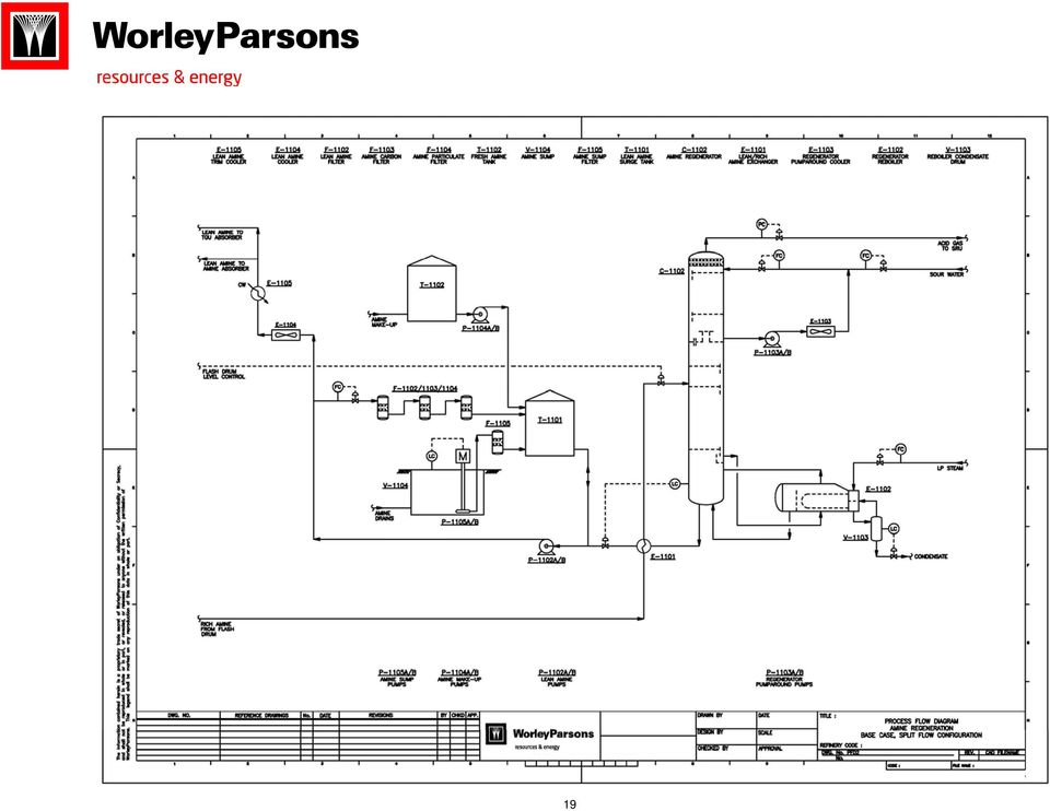
9 4. Acid Gas Injection is another option instead of sulfur recovery unit that could be evaluated with a different criteria and the acid gas behavior at high pressure using high pressure compressors. If COS presents in the treated gas, membranes could be used. Mercury is another substance commonly present in natural gas, and particularly in LNG facilities it must be removed to meet the product specification. Activated carbon in a non regenerable adsorbent bed is commonly used for mercury removal. Recent WorleyParsons Experience WorleyParsons recently evaluated different schemes and solvent for bulk acid gas removal versus selective solvent. Sour Gas Field Developments normally includes amine unit or sulfur removal unit, Dehydration, SRU, TGU and incineration. A typical flow diagram and the process flow diagram for the Case 2 are provided on the following pages. Two schemes will be described. Case 1 our evaluation for new Upgraders and Oil Sands mostly in Canada dealing with a lot of high content H2S and CO2 in sour gas indicates that using DGA solvent in the amine unit will meet the product specification. There will be more CO 2 and H 2 S to the sulfur recovery unit since DGA absorbs most of the H 2 S and CO 2. The Claus unit is then followed by the BSR/TGU-amine tail gas treatment unit. MDEA solvent is selected in the tail gas unit and the evaluation of potential benefits of using selective solvent such as Flexsorb or similar is in progress. Case 2 - Our evaluation indicates that using common regeneration unit for the amine unit and the tail gas unit is very cost effective in reducing capital and operating cost. The amine unit is designed with a special features of split flow configuration and using turbine to save the electricity where the pressure from the absorber bottom will let down to a lower pressure. TEG is selected for the dehydration unit. Common Regeneration unit lower operating and capital cost Absorber with split flow configuration Smaller reboiler duty Recover the majority of horse power required by recovering the energy from absorber bottom One solvent, less operating cost Easier to operate A brief description of our schemes is described below. The sulfur recovery and BSR-TGU is not included since it is typical WorleyParsons design features. 9

10 (Sulfur Removal) Amine Process Description The amine unit is an integrated split flow configuration and a common regeneration with the tail gas unit. MDEA flows into the Amine absorber where H 2 S is preferentially absorbed by the MDEA solution. The MDEA solution reduces the H 2 S content in the absorber overhead stream to less than 4 ppmv. A 50 wt% MDEA solution is used to treat the acid gas. The absorber is split into two sections, the absorption section and the water wash section. The absorption section of the tower is trayed with lean solution feed to top of each bed. The absorption section serves as the main contacting section between the gas feed stream and the lean MDEA solution. The water wash section is contained one section and is provided above the lean solution feed point to minimize solvent losses in the treated product stream. A de-entrainment device is also provided above the water wash section of the absorber to minimize the entrainment of liquid out of the top of the absorber in the treated gas. The amine absorber water wash section is integrated in the column shell and provides separation of entrained MDEA and wash water from the overhead gas. Wash water is drawn from the chimney tray top section of the amine absorber, pumped and injected into the absorber top through a flow control valve. Fresh makeup cold condensate is added to the circulating wash water loop and a small purge stream is continuously withdrawn to keep the concentration of MDEA in the wash water relatively low. This minimizes MDEA losses. Treated gas from the Amine absorber overhead gas flows to the dehydration unit. Rich MDEA leaving the bottom of the absorber operates at high pressure the energy could be recovered as a electricity by providing a turbine to recover the energy. The energy being recovered by the turbine will provide abut 70 to 80% of the required horse power in the sulfur block. Rich MDEA is sent to the flash drum to remove any hydrocarbon in the solution, by providing a flash section at the top of the drum, then is preheated in the lean/rich MDEA exchanger before entering the regenerator below the wash trays through a flow control valve, which is designed for flashing service. The amine absorber will have two MDEA streams, one from the Tail Gas Treating Unit absorber as a semi-lean and another from the amine regeneration as a lean solution. This process is integrated split flow configuration that the amine absorber will be provided with the semi-lean and super lean MDEA with a common regeneration that serves TGU absorber and the amine absorber. The circulation rate is reduced and the size of the regeneration is smaller due to less circulation rate. Therefore, the Reboiler and associated equipment will be smaller. The CO 2 and H 2 S are stripped from the rich MDEA solution in the 24-stripping tray MDEA regenerator by cascading the rich solution, counter-current to steam produced by the Reboiler. The top section of the regenerator tower contains a rectifying (reflux) section consisting of 4 trays for washing of the stripped acid gas. Stripping steam is formed in the Regenerator Reflux Reboiler, and reboiler heat is supplied from the LP steam system. The stripped CO 2 and H 2 S then flow to the sulfur recovery unit. The lean MDEA solution is collected on a chimney tray, which distributes the solution to the reboiler. As the lean solution passes through the reboiler, stripping steam is generated and flows up the 10

11 column, while the lean solution is returned to the sump section in the base of the column. This stripping steam provides agitation and the heat to release the absorbed H 2 S and CO 2 from the rich MDEA solution, as it rises up through the column, counter-current to the rich MDEA solution. The reboiler is equipped with the Reboiler condensate pot. The regenerator column consists of a lower stripping section and an upper condensing section. The stripping heat is provided by saturated low-pressure steam through a kettle-type regenerator Reboiler. In the condensing section, the rising vapor is cooled by contact with sub-cooled quench water. The quench water is recycled and cooled. The cooling load is adjusted to control the overhead gas temperature. Overhead gas from the regenerator is recycled to the front of the Claus sulfur recovery unit. A de-entrainment device is provided above the top tray of the tower to minimize the entrainment of liquid out of the top of the regenerator tower into the acid gas stream. Lean MDEA is pumped through Hot Lean pump then pre-cooled in the lean/rich MDEA exchanger. The MDEA is further cooled in the lean MDEA air cooler and lean MDEA trim cooler. The MDEA storage tank has capacity to hold the total MDEA inventory and is used to take system surges during operation. The tank also serves as a convenient location for MDEA make-up. The MDEA make up from truck connection and cold condensate is provided to the surge tank. Nitrogen blanketing prevents degradation of the MDEA by preventing oxygen to the tank. The cooled lean MDEA is pumped through Lean MDEA circulation pump. A slip stream of the MDEA is circulated through lean Filter where solid impurities such as iron oxide, iron sulfide, pipe scale, dirt, and degradation products are removed from the solution. In the Future, after full MDEA filtration, a slipstream may be routed to the Carbon Filter, where soluble MDEA degradation products, more commonly referred to as Heat Stable Salts (HSS), would be removed through adsorption into the carbon active sites. The operation of the Carbon Bed is important to controlling foaming and corrosion in the MDEA unit. Samples of the MDEA solution upstream and downstream of the Carbon Bed should be taken periodically, and the content of Heat Stable Salts should be determined and compared to previous samples. When the capacity of the carbon reaches saturation, inlet and outlet analyses will be indistinguishable. Before this occurs, the carbon should be replaced with fresh charge of activated carbon. The activated carbon in the Carbon Filter will become prematurely saturated with anti-foam constituents instead of the Heat Stable Salt constituents. Downstream of the rich, lean filtration and on the quench water line to the regenerator, provisions for anti-foam injection are included and should be used only if required. Excess use of anti-foam should be avoided. The cool, lean, and filtered MDEA solution is returned to the Lean MDEA line and the lean MDEA is routed to the Absorber on flow control valve. The lean MDEA will be routed to two different nozzle locations at the normal operation. A third nozzle connection and a new bed will be considered for future expansion. 11

12 The collected drain will be routed to the sump, which is a concrete sump under ground. The sump pump is designed to transfer the liquid from the sump to the bottom of the MDEA absorber (or to the Surge Tank). The Filter is located downstream of the pump-out pump. Nitrogen blanketing prevents degradation of the MDEA by preventing oxygen to the sump. Amine Tail Gas Treating Process Description Tail gas from the contact condenser flows into the amine absorber where H 2 S is preferentially absorbed by the amine solution. The amine solution reduces the H 2 S content in the absorber overhead stream to less than 150 ppmv. The amine solution is a 50-wt% solution of MDEA in water. A packed column is used to minimize the pressure drop through the absorber. The amine absorber overhead K.O. drum, integral with the absorber column, provides separation of entrained amine and wash water from the overhead gas. Wash water circulated by the wash water pump is injected into the absorber overhead line upstream of the K.O. drum. Fresh makeup condensate is added to the circulating wash water loop and a small purge stream is continuously withdrawn to keep the concentration of amine in the wash water relatively low to minimize amine losses. Tail gas absorber overhead gas flows to the thermal oxidizer for oxidation and release to the atmosphere. Rich amine is pumped from the bottom of the amine absorber to the amine absorber as a semi-lean solution to the amine absorber. Lean amine is provided from the common regenerator in the amine unit to the TGU absorber. Incinerator The gases exiting the amine Absorbers are routed to the Incinerator. Fuel gas is burned with excess air to a sufficient temperature to heat the tail gas from the tail gas unit. The current design represents a natural draft Incinerator. The Thermal Oxidizer is designed to oxidize the residual amount of Hydrogen Sulfide (H 2 S) and other sulfur compounds in the tail gas to Sulfur Dioxide (SO 2 ), and raise the temperature of the waste gas stream from the TGTU to about 1200 F (648 C). Higher temperature has to be achieved if CO destruction required. Fuel gas and air are combusted in the Thermal Oxidizer and then the waste gas stream (primarily CO 2 and N 2 ) is added so that any sulfur compounds are completely oxidized and mixed. The temperature is normally sufficient to oxidize the residual H 2 S and other sulfur components to SO 2, while minimizing SO 3 formation. The hot combustion gas exits the facility through the Stack. The Stack is equipped with an Oxygen/CO/SO 2 analyzer, to monitor the excess Oxygen in the Stack gas along with an analyzer, to monitor the Sulfur Dioxide (SO 2 ) content to the Stack gas. In addition to the analyzers, the Stack is equipped with a thermocouple, to monitor the Stack temperature. 12

13 2. TEG Dehydration Process Description The Sales gas from the Amine Unit is sent to the Dehydration Unit, for which we have slected TEG as the drying solvent. There are other dehydration processes that could be selected. The Sales Gas from the each amine Absorber in the acid gas removal is routed to the Dehydration units. The Dehydration TEG Contactor is an absorption column with structure packing. The wet gas is fed to the bottom of the column and the lean TEG is fed to the top of the column. The TEG absorbs water from the wet gas as the two streams are contacted counter-currently in the column. The rich TEG flows to the bottom and is sent to the sales gas dehydration feed/ovhd exchanger to heat the solution prior to entering the Sales gas dehydration TEG flash drum. The rich TEG solution from the flash drum is filtered in the Sales Gas dehydration rich filter. The rich TEG solution is routed to the TEG Regeneration Unit, which is a package unit through the dehydration lean / rich exchanger. The dried gas exits the top of the column and is sent to the Sales gas dehydration/dry gas/lean solution exchanger, to cool the stripper OVHD gas and heat the dry gas, before it is sent to the sales gas compression. The basic components in the TEG Regeneration Package are as follows: Sales Gas Dehydration Regeneration Column is where the water in the rich TEG is stripped off. The Regenerator includes a tray section in part A and a packed column in part B. Sales gas Dehydration Regeneration Reboiler is a bath type Reboiler. It supplies the heat for stripping via Glycol. It is located directly under the Regenerator Column. Sales Gas Dehydration TEG Surge Drum directly receives the lean TEG from the Reboiler. The Sales Gas dehydration regeneration is operated with the dry fuel gas as a strip gas. The fuel gas is introduced to the reboiler through the fuel gas filter. The overhead vapor from the Regenerator Column is cooled by heating the Rich TEG solution with the Sales Gas dehydration TEG Feed/OVHD Exchanger and then is routed to the Sales Gas dehydration Regeneration OVHD KO. Drum to separate the condensate water. The separated gas then is sent to the Sales Gas Dehydration TEG Vent compressor. Condensate water separated from the KO drum is pumped to the sales Gas TEG regeneration. The compressed gas is cooled in the Sales gas Dehydration TEG OVHD Cooler. The condensed water is separated in the Sales Gas Dehydration KO drum and the gas is routed to the CO 2 compression unit. The lean TEG from the sales gas Dehydration regeneration section is sent to the Sales Gas dehydration Lean/rich Exchanger to exchange the heat to the rich solution. The lean TEG solution is further cooled in the Sales Gas dehydration Dry gas/lean solution exchanger. 13

14 The lean TEG solution is filtered in the Sales Gas Dehydration Particulate filter. A slipstream from the lean TEG is sent to the Dehydration Charcoal filter and the guard filter respectively. The lean TEG solution is then pumped to the sales Gas Dehydration TEG contactor. The TEG make-up will be pumped through Sales Gas dehydration TEG make-up pump and the Sales Gas Dehydration TEG sump filter to the Rich TEG solution prior entering the TEG rich flash drum. A common TEG sump will serve both the Sales Gas dehydration and the CO 2 dehydration units to collect the TEG drainage. The solution from the TEG sump is pumped by the Sales Gas Dehydration TEG sump pump, and will be routed to the TEG rich flash drum joining the TEG make-up. For Case 2 application, the following are the typical feed gas compositions and the product specification for natural gas application in the gas plant. Component Composition ( % mol ) He 0.01 H N CO (2) H 2 S (1) CH C 2 H C 3 H Organic S <150 mg/nm 3 Total 100 Critical Temperature, K Critical Pressure, Mpa (a) Temperature, C 25~30 Pressure, Mpa (a) 8.3 It was Assume: H 2 S content: 13-18%, CO 2 content: 8-11%, and Sour feed gas also contains organic sulfur compounds: content of organic sulfur compounds <150mg/m3. Sour feed natural gas is saturated with water and also contains some solid particles (maximum average of 0.2 mg / m3). The treated natural gas will contain less than 6mg/Nm 3 (20C, Pa) of H2S, less than 3vol % of CO2 and less than 200mg/Nm 3 (20, Pa) of sulfide. The typical specification of the water dew point of treated natural gas will be -10 C. The Sulfur Recovery Unit shall recover essentially minimum 99.9 wt. percent of the sulfur contained in the feedstock. The vent gas leaving the absorber of the Tail gas treating section shall contains no more than 150 ppmv of sulfide. The liquid sulfur shall contain no more than 10 ppmv of H 2 S. 14

15 Refer to Block Flow diagram and the process flow diagram for case 2 study. Case -3 WorleyParsons experience on LNG application indicates using activated MDEA is a very cost effective solvent to meet pipeline specifications and followed by dehydration unit to meet the water specifications. A typical LNG feed composition is provided below. LNG Typical Feed Gas Composition Component Composition (mol %) CO N CH C2H C3H n-c i-c C C C C C H2S 0.01 Total 100 PROPERTIES Temperature C 60 Pressure Bara 50 References: Rameshni, M. State of the Art in Gas Treating, presented at British Suphur, 2000, San Francisco, CA, USA. 15

16 BP Boqueron is an Enhanced Oil Recovery (EOR) project at an existing field located in eastern Venezuela. WorleyParsons was awarded the project management and construction management services contract by the Saudi Arabian Oil Company (Saudi Aramco) for the Hawiyah Gas Development Project. 16

17 17

18 18

19 19
20 20

State-of-the-Art In Gas Treating
 State-of-the-Art In Gas Treating Mahin Rameshni, P.E. Chief Process Engineer WorleyParsons 125 West Huntington Drive Arcadia, CA, USA Phone: 626-294-3549 Fax: 626-294-3311 E-Mail: [email protected]
IBP 2778_10 HIGH EFFICIENCY ON CO2 REMOVAL IN NATURAL GAS WITH UCARSOL SOLVENTS Thiago V. Alonso 1. Abstract. 1. Introduction
 IBP 2778_10 HIGH EFFICIENCY ON CO2 REMOVAL IN NATURAL GAS WITH UCARSOL SOLVENTS Thiago V. Alonso 1 Copyright 2010, Brazilian Petroleum, Gas and Biofuels Institute - IBP This Technical Paper was prepared
How To Make A Mine Guard Fosil Process
 UOP Amine Guard TM FS Technology for Acid Gas Removal 2009 UOP LLC. All rights reserved. UOP 5241B-01 Agenda Overview of the Amine Guard FS process UCARSOL TM Solvent characteristics Amine Guard FS flow
Dow Solvent Technologies for CO 2 Removal
 Dow Oil & Gas Jan Lambrichts AIChE Netherlands / Belgium Section 21 January 2014 Novotel, Antwerp Dow Solvent Technologies for CO 2 Removal Who We Are Dow combines the power of science and technology to
How To Make A High Co 2 Gas Blend
 ECONOMICAL OPTION FOR CO 2 / METHANE SEPARATION IN PRODUCED GAS CONTAINING A HIGH CO 2 FRACTION F. Patrick Ross, P.E. TPR Consulting 9907 Sagecourt Drive Houston, Texas 77089 (713) 870-9208 [email protected]
CHAPTER 7 THE DEHYDRATION AND SWEETENING OF NATURAL GAS
 CHAPTER 7 THE DEHYDRATION AND SWEETENING OF NATURAL GAS Natural gases either from natural production or storage reservoirs contain water, which condense and form solid gas hydrates to block pipeline flow
SAMPLE CHAPTERS UNESCO EOLSS NATURAL GAS PROCESSING. H. K. Abdel-Aal National Research Center (NRC), Cairo, Egypt
, Cairo, Egypt") NATURAL GAS PROCESSING H. K. Abdel-Aal National Research Center (NRC), Cairo, Egypt Keywords: sour natural gas, gas sweetening, gas dehydration, amines, glycols, hydrates, hydrogen sulfide, NGL, cryogenic
NATURAL GAS PROCESSING H. K. Abdel-Aal National Research Center (NRC), Cairo, Egypt Keywords: sour natural gas, gas sweetening, gas dehydration, amines, glycols, hydrates, hydrogen sulfide, NGL, cryogenic
How To Run A Power Plant
 CO 2 Capture at the Kemper County IGCC Project 2011 NETL CO 2 Capture Technology Meeting Kemper County IGCC Overview 2x1 Integrated Gasification Combined Cycle (IGCC) 2 TRansport Integrated Gasifiers (TRIG
WATER WALL BOILER FOR AIR AND OXYGEN FIRED CLAUS SULPHUR RECOVERY UNITS
 WATER WALL BOILER FOR AIR AND OXYGEN FIRED CLAUS SULPHUR RECOVERY UNITS Abstract Mahin RAMESHNI, P.E. Technical Director, Sulphur Technology [email protected] WorleyParsons 125 West Huntington
Morphysorb /Genosorb Physical solvents for acid gas removal
 Morphysorb /Genosorb Physical solvents for acid gas removal Our new name is ThyssenKrupp Industrial Solutions www.thyssenkrupp-industrial-solutions.com ThyssenKrupp Uhde 2 Table of contents 1. Company
HYDROCARBON REMOVAL FROM AMINES DEMONSTRATED EXPERIENCE ABSTRACT
 HYDROCARBON REMOVAL FROM AMINES DEMONSTRATED EXPERIENCE Technical Article Presented at Gas Processors Association Annual Convention San Antonio, Texas, USA, March 16, 2005 By Gary L. Lawson, PE (Presenter)
The Single Absorption Scrubbing Sulfuric Acid Process
 The Single Absorption Scrubbing Sulfuric Acid Process Leonard J. Friedman, Samantha J. Friedman Acid Engineering & Consulting, Inc. 17770 Deauville Lane, 33496, USA [email protected] Keywords: Sulfuric
Hybrid Systems: Combining Technologies Leads to More Efficient Gas Conditioning
 Hybrid Systems: Combining Technologies Leads to More Efficient Gas Conditioning Introduction William Echt UOP LLC Various processes are used to condition raw natural gas to pipeline quality. Acid gas removal
Gas Treating Products and Services. Gas Treating Technologies and Services. Alkyl Alkanolamines, Ethanolamines, and Isopropanolamines
 DOW Gas Treating Products and Services Gas Treating Technologies and Services UCARSOL and SELEXOL Solvents Alkyl Alkanolamines, Ethanolamines, and Isopropanolamines WORLD CLASS PRODUCTS FROM THE WORLD
Natural Gas. Natural Gas... p. 57 to 59. fin-house f Training... p. 61
 ff... p. 57 to 59 fin-house f Training... p. 61 Foundation Can be organized for a single company* Production - Treatments - Transport - End Uses 5 Days Reference PROD / NATGAS PROD / GAZNAT Purpose To
AMMONIA AND UREA PRODUCTION
 AMMONIA AND UREA PRODUCTION Urea (NH 2 CONH 2 ) is of great importance to the agriculture industry as a nitrogen-rich fertiliser. In Kapuni, Petrochem manufacture ammonia and then convert the majority
NATURAL GAS EXPERIENCE
 02 NATURAL GAS EXPERIENCE Linde Process Plants, Inc. (LPP) has constructed NGL Plants since 1969 using traditional processes as well as the more advanced CRYO-PLUS technology. CRYO-PLUS TM Proprietary
MERCURY REMOVAL FROM NATURAL GAS AND LIQUID STREAMS ABSTRACT. Giacomo Corvini, Julie Stiltner and Keith Clark UOP LLC Houston, Texas, USA
 MERCURY REMOVAL FROM NATURAL GAS AND LIQUID STREAMS Giacomo Corvini, Julie Stiltner and Keith Clark UOP LLC Houston, Texas, USA n ABSTRACT Mercury is often present in natural gas, petrochemical and some
www.klmtechgroup.com TABLE OF CONTENT
 Page : 1 of 38 Project Engineering Standard www.klmtechgroup.com KLM Technology #03-12 Block Aronia, Jalan Sri Perkasa 2 Taman Tampoi Utama 81200 Johor Bahru Malaysia CAUSTIC AND CHEMICAL TABLE OF CONTENT
Corrosion Management in Gas Treating Plants (GTP s): Comparison between Corrosion Rate of DEA and MDEA A Case Study in Sour Gas Refinery
: Comparison between Corrosion Rate of DEA and MDEA A Case Study in Sour Gas Refinery") Proceedings of the 214 International Conference on Industrial Engineering and Operations Management Bali, Indonesia, January 7 9, 214 Corrosion Management in Gas Treating Plants (GTP s): Comparison between
Proceedings of the 214 International Conference on Industrial Engineering and Operations Management Bali, Indonesia, January 7 9, 214 Corrosion Management in Gas Treating Plants (GTP s): Comparison between
SULFUR RECOVERY UNIT. Thermal Oxidizer
 SULFUR RECOVERY UNIT Thermal Oxidizer BURNERS FLARES INCINERATORS PARTS & SERVICE SULFUR RECOVERY UNIT Thermal Oxidizer Tail Gas Thermal Oxidizer designed and built to GOST-R requirements. Zeeco can meet
Fact Sheet Technology. Bergius-Pier Process (1)
") tec Energy Technology Projects Subject: Bergius 1: 1924 1945 Rev: April 2006 Fact Sheet Technology The information included in this document is property of. Use and reproduction of this document, without
tec Energy Technology Projects Subject: Bergius 1: 1924 1945 Rev: April 2006 Fact Sheet Technology The information included in this document is property of. Use and reproduction of this document, without
Advances in Membrane Materials Provide New Solutions in the Gas Business
 Advances in Membrane Materials Provide New Solutions in the Gas Business Authors: Pat Hale, Randall Gas Technologies-ABB Lummus Global Inc, Kaaeid Lokhandwala, Membrane Technology and Research, Inc. Presenter:
Liquefied Natural Gas (LNG)
") Graduate Diploma in Petroleum Studies Major in Liquefied Natural Gas (LNG) INDUCTION Launching ceremony Week 39, 2012 Administration / Plant visit / Fundamentals of LNG and LNG main risks awareness Module
Graduate Diploma in Petroleum Studies Major in Liquefied Natural Gas (LNG) INDUCTION Launching ceremony Week 39, 2012 Administration / Plant visit / Fundamentals of LNG and LNG main risks awareness Module
ECONOMICAL OPTIONS FOR RECOVERING NGL / LPG AT LNG RECEIVING TERMINALS
 ECONOMICAL OPTIONS FOR RECOVERING NGL / LPG AT RECEIVING TERMINALS Presented at the 86 th Annual Convention of the Gas Processors Association March 13, 2007 San Antonio, Texas Kyle T. Cuellar Ortloff Engineers,
TODAY S THERMAL OXIDIZER SOLUTIONS TO MEET TOMORROW S CHALLENGES
 Callidus Oxidizers for Waste Destruction TODAY S THERMAL OXIDIZER SOLUTIONS TO MEET TOMORROW S CHALLENGES Thermal oxidizer systems Catalytic oxidizer systems Callidus, experts in Thermal Oxidizers Wide
UOP Gas Processing. Realizing the Value of Your Natural Gas and Synthesis Gas Resources
 UOP Gas Processing Realizing the Value of Your Natural Gas and Synthesis Gas Resources Gas Processing Solutions The golden age of gas Experts agree that by 2035 global gas use will rise by more than 50
www.klmtechgroup.com TABLE OF CONTENT
 Page : 1 of 29 Project Engineering Standard www.klmtechgroup.com KLM Technology #03-12 Block Aronia, Jalan Sri Perkasa 2 Taman Tampoi Utama 81200 Johor Bahru Malaysia TABLE OF CONTENT SCOPE 2 REFERENCES
Dry-out Design Considerations and Practices for Cryogenic Gas Plants
 Dry-out Design Considerations and Practices for Cryogenic Gas Plants Presented at the 93 rd Annual Convention of the Gas Processors Association April 14, 2014 Dallas, Texas Joe T. Lynch, P.E., David A.
Increasing Efficiency of Hot Potassium Carbonate CO 2 Removal Systems
 Increasing Efficiency of Hot Potassium Carbonate CO 2 Removal Systems Stanislav Milidovich, P.E. and Edward Zbacnik UOP LLC ABSTRACT The UOP Benfield Process is the original hot potassium carbonate technology
AM-08-14 Cost Effective Solutions for Reduction of Benzene in Gasoline
 Annual Meeting March 9-11, 2008 Manchester Grand Hyatt San Diego, CA Cost Effective Solutions for Reduction of Benzene in Gasoline Presented By: Kerry Rock Director, Technology Commercialization CDTECH
Nitrogen Blanketing for Methanol Storage and Transportation
 Nitrogen Blanketing for Methanol Storage and Transportation Overview Air is the enemy of many materials. Not only can oxygen cause safety concerns and product degradation, but moisture, dirt, hydrocarbons
Hydrogen Production via Steam Reforming with CO 2 Capture
 Hydrogen Production via Steam Reforming with CO 2 Capture Guido Collodi Foster Wheeler Via Caboto 1, 20094 Corsico Milan - Italy Hydrogen demand in refineries is increasing vigorously due to the stringent
RAILROAD COMMISSION OF TEXAS APPENDIX C LIST OF E&P WASTES: EXEMPT AND NONEXEMPT
 RAILROAD COMMISSION OF TEXAS APPENDIX C LIST OF E&P WASTES: EXEMPT AND NONEXEMPT WASTE MINIMIZATION IN THE OIL FIELD - APPENDIX C NOTES RAILROAD COMMISSION OF TEXAS LIST OF E&P WASTES: EXEMPT AND NON EXEMPT
The Sorbead Quick-Cycle Process For Simultaneous Removal of Water, Heavy Hydrocarbons and Mercaptans from Natural Gas
 The Sorbead Quick-Cycle Process For Simultaneous Removal of Water, Heavy Hydrocarbons and Mercaptans from Natural Gas Presented at the Laurance Reid Gas Conditioning Conference February 25-27, 2007 Michael
Clayton Maugans, Ph.D. Siemens Water Technologies. Mike Howdeshell, Ph.D. Siemens Water Technologies. Steve De Haan Lummus Technology
 THE EFFECTS OF CAUSTIC TOWER OPERATIONS AND SPENT CAUSTIC HANDLING ON THE ZIMPRO WET AIR OXIDATION (WAO) OF ETHYLENE SPENT CAUSTIC Clayton Maugans, Ph.D. Siemens Water Technologies Mike Howdeshell, Ph.D.
LEAN LNG PLANTS HEAVY ENDS REMOVAL AND OPTIMUM RECOVERY OF LIGHT HYDROCARBONS FOR REFRIGERANT MAKE-UP
 LEAN LNG PLANTS HEAVY ENDS REMOVAL AND OPTIMUM RECOVERY OF LIGHT HYDROCARBONS FOR REFRIGERANT MAKE-UP Laurent Brussol Dominique Gadelle Arnaud Valade Process & Technologies Division Technip Paris La Défense
Hydrogen from Natural Gas via Steam Methane Reforming (SMR)
") Hydrogen from Natural Gas via Steam Methane Reforming (SMR) John Jechura [email protected] Updated: January 4, 2015 Energy efficiency of hydrogen from natural gas Definition of energy efficiency From
Hydrogen from Natural Gas via Steam Methane Reforming (SMR) John Jechura [email protected] Updated: January 4, 2015 Energy efficiency of hydrogen from natural gas Definition of energy efficiency From
Natural Gas Filtration Applications
 Natural Gas Filtration Applications Natural gas is an abundant clean-burning fuel that provides an important part of the overall energy usage in the United States. Gas (CH 4 ), also known as methane, undergoes
NGL RECOVERY PLANT: TREATER OPTIMIZATION FOR WATER AND MERCAPTAN REMOVAL
 NGL RECOVERY PLANT: TREATER OPTIMIZATION FOR WATER AND MERCAPTAN REMOVAL Nancy Hillenbrand and Keith Clark UOP LLC Houston, Texas ABSTRACT A number of process and product considerations contribute to the
Sulfur Tail Gas Thermal Oxidizer Systems By Peter Pickard
 Sulfur Tail Gas Thermal Oxidizer Systems By Peter Pickard Introduction SRU s (Sulfur Recovery Units) are critical pieces of equipment in refineries and gas plants. SRUs remove sulfur compounds from certain
FLEXICOKING technology for upgrading heavy oil and utilization of by-products
 FLEXICOKING technology for upgrading heavy oil and utilization of by-products 2007 Japan-China-Korea Petroleum Technology Seminar Tokyo Dec 3-5, 2007 Toa Oil Co.Ltd Kenya Takahashi Background Driver -
Natural Gas Dehydrator Optimization
 Natural Gas Dehydrator Optimization IAPG & US EPA Technology Transfer Workshop November 5, 2008 Buenos Aires, Argentina Natural Gas Dehydration: Agenda Methane Losses Methane Recovery Is Recovery Profitable?
Putting a chill on global warming
 Carbon capture and storage Putting a chill on global warming SABINE SULZER SULZER PUMPS MARKUS DUSS SULZER CHEMTECH Whenever fuel is burned, carbon dioxide (CO ) is emitted into the atmosphere. The subsequent
Lecture 35: Atmosphere in Furnaces
 Lecture 35: Atmosphere in Furnaces Contents: Selection of atmosphere: Gases and their behavior: Prepared atmospheres Protective atmospheres applications Atmosphere volume requirements Atmosphere sensors
Challenges with Thermal Combustion Stage in Sulphur Recovery Designs
 Challenges with Thermal Combustion Stage in Sulphur Recovery Designs Mahin Rameshni, P.E. Technical Director, Sulphur Technology and Gas Processing WorleyParsons181 West Huntington Drive, Monrovia, 91016,
Assignment 8: Comparison of gasification, pyrolysis and combustion
 AALTO UNIVERSITY SCHOOL OF CHEMICAL TECHNOLOGY KE-40.4120 Introduction to biorefineries and biofuels Assignment 8: Comparison of gasification, pyrolysis and combustion Aino Siirala 309141 Assignment submitted
Syngas Purification Units
 Syngas Purification Units From Gasification to Chemicals www.airliquide.com Global experience Since the integration of Lurgi, a pioneer in gasification technologies, Air Liquide has widely expanded its
Description of Thermal Oxidizers
 Description of Thermal Oxidizers NESTEC, Inc. is a full service equipment supplier specializing in solutions for plant emission problems. The benefit in working with NESTEC, Inc. is we bring 25+ years
ASimple Guide to Oil Refining
 ASimple Guide to Oil Refining We all know that motor oil and gasoline come from crude oil. What many people do not realize is that crude oil is also the starting point for many diverse products such as
Enhancing SRUs with oxygen-enriched air
 M ost refiners have now moved toward a higher standard of s u l p h u r - r e c o v e ry efficiency to comply with clean fuels regulations that impose a reduction of sulphur in refined products. While
Industry Description and Practices. Waste Characteristics
 Pollution Prevention and Abatement Handbook WORLD BANK GROUP Effective July 1998 Industry Description and Practices The petroleum industry is organized into four broad sectors: exploration and production
SUPERSONIC GAS CONDITIONING - COMMERCIALISATION OF TWISTER TECHNOLOGY
 87th Annual Convention Grapevine, Texas, USA March 2-5, 2008 SUPERSONIC GAS CONDITIONING - COMMERCIALISATION OF TWISTER TECHNOLOGY Peter Schinkelshoek MSc Eng Twister BV Principal Process Engineer [email protected]
Linde Engineering. Natural Gas Processing Plants.
 Linde Engineering Natural Gas Processing Plants. 2 Contents. 3 Introduction 4 Components and pretreatment of natural gas 5 Natural gas plants 6 Extraction of hydrocarbons and LPG plants 7 References for
Biogas as transportation fuel
 Biogas as transportation fuel Summary Biogas is used as transportation fuel in a number of countries, but in Europe it has only reached a major breakthrough in Sweden. All of the biogas plants in Sweden
SIX REASONS TO DRY BIOGAS To A LOW DEWPOINT BEFORE COMBUSTION IN A CHP ENGINE STEVEN SCOTT MARKET DEVELOPMENT MANAGER ALTERNATIVE ENERGIES
 SIX REASONS TO DRY BIOGAS To A LOW DEWPOINT BEFORE COMBUSTION IN A CHP ENGINE STEVEN SCOTT MARKET DEVELOPMENT MANAGER ALTERNATIVE ENERGIES Filippo Turra Product Manager Cooling Technology INTRODUCTION
DEGASSED CATION CONDUCTIVITY MEASUREMENT
 (Presented at EPRI's 8th International Conference on Cycle Chemistry in Fossil and Combined Cycle Plants with Heat Recovery Steam Generators - June 20-23, 2006 Calgary, Alberta Canada) DEGASSED CATION
Long-Term Demonstration of CO2 Recovery from the Flue Gas of a Coal-Fired Power Station
 Long-Term Demonstration of CO2 Recovery from the Flue Gas of a Coal-Fired Power Station MASAKI IIJIMA* 1 SHOJIRO IWASAKI* 1 SHINYA KISHIMOTO* 1 TORU TAKASHINA* 2 SUSUMU OKINO* 2 There is now a growing
Dehydration. Dehydration UNIT. operations. bioprocess plants
 Dehydration Dehydration UNIT operations bioprocess plants VOGELBUSCH MOLECULAR SIEVE DEHYDRATION PRESSURE SWING ADSORPTION PROCESS By merging specialized process know-how with existing technology Vogelbusch
Nitrogenous Fertilizer Plants
 Multilateral Investment Guarantee Agency Environmental Guidelines for Nitrogenous Fertilizer Plants Industry Description and Practices This document addresses the production of ammonia, urea, ammonium
The Shell-Paques/THIOPAQ Gas Desulphurisation Process: Successful Start Up First Commercial Unit.
 The Shell-Paques/THIOPAQ Gas Desulphurisation Process: Successful Start Up First Commercial Unit. Alex Benschop and Albert Janssen 1, Alie Hoksberg 2, Munaf Seriwala 3, Ray Abry 4 and Charles Ngai 5 1
Control Device Requirements Charts For Oil and Gas Handling and Production Facilities
 Device Charts For Oil and Gas Handling and Production Facilities Purpose/Scope: The purpose of this document is to provide standardized guidance for use by the regulated community and air permit reviewers,
CONTINUED DEVELOPMENT OF GAS SEPARATION MEMBRANES
 CONTINUED DEVELOPMENT OF GAS SEPARATION MEMBRANES FOR HIGHLY SOUR SERVICE Tom Cnop *, David Dortmundt and Mark Schott UOP LLC, 25 East Algonquin Road, Des Plaines, Illinois 60017, U.S.A. INTRODUCTION The
Molecular Sieve Adsorbents
 Adsorption Technologies: our work our life our passion. Molecular Sieve Adsorbents Zeochem Molecular Sieve Adsorbents Zeochem, a manufacturer of high quality molecular sieves and chromatography gels, was
Balancing chemical reaction equations (stoichiometry)
") Balancing chemical reaction equations (stoichiometry) This worksheet and all related files are licensed under the Creative Commons Attribution License, version 1.0. To view a copy of this license, visit
Balancing chemical reaction equations (stoichiometry) This worksheet and all related files are licensed under the Creative Commons Attribution License, version 1.0. To view a copy of this license, visit
INTRODUCTION. Fact Sheet: Air Pollution Emission Control Devices for Stationary Sources
 Fact Sheet: Air Pollution Emission Control Devices for Stationary Sources INTRODUCTION Stationary sources of air pollution emissions, such as power plants, steel mills, smelters, cement plants, refineries,
WASTE WATER TREATMENT SYSTEM (OPERATING MANUALS )
") Page 1 of 76 1.0 PURPOSE The purpose of the Wastewater Treatment System is to remove contaminates from plant wastewater so that it may be sent to the Final Plant Effluent Tank and eventually discharged
Page 1 of 76 1.0 PURPOSE The purpose of the Wastewater Treatment System is to remove contaminates from plant wastewater so that it may be sent to the Final Plant Effluent Tank and eventually discharged
SENSITIVITY ANALYSIS OF A NATURAL GAS TRIETHYLENE GLYCOL DEHYDRATION PLANT IN PERSIAN GULF REGION
 Petroleum & Coal ISSN 1337-7027 Available online at www.vurup.sk/pc Petroleum & Coal 53 (1) 71-77, 2011 SENSITIVITY ANALYSIS OF A NATURAL GAS TRIETHYLENE GLYCOL DEHYDRATION PLANT IN PERSIAN GULF REGION
RISKS OF ACCUMULATED SULFUR IN SULFUR RECOVERY UNITS
 RISKS OF ACCUMULATED SULFUR IN SULFUR RECOVERY UNITS By: Ellen Ticheler-Tienstra, Anne van Warners, Rien van Grinsven and Sander Kobussen of Jacobs Comprimo Sulfur Solutions Abstract While recovering sulfur
Nitrogenous Fertilizer Plants
 Pollution Prevention and Abatement Handbook WORLD BANK GROUP Effective July 1998 Nitrogenous Fertilizer Plants Industry Description and Practices This document addresses the production of ammonia, urea,
Natural gas liquids recovery from gas turbine fuel
 Natural gas liquids recovery from gas turbine fuel By Simone Amidei, Francesca Monti, Riccardo Valorosi / GE Oil & Gas GE imagination at work Natural gas liquids recovery from gas turbine fuel By Simone
PERFORMANCE EVALUATION OF NGCC AND COAL-FIRED STEAM POWER PLANTS WITH INTEGRATED CCS AND ORC SYSTEMS
 ASME ORC 2015 3rd International Seminar on ORC Power Systems 12-14 October 2015, Brussels, Belgium PERFORMANCE EVALUATION OF NGCC AND COAL-FIRED STEAM POWER PLANTS WITH INTEGRATED CCS AND ORC SYSTEMS Vittorio
www.klmtechgroup.com TABLE OF CONTENT
 Page : 1 of 23 Rev: 01 Project Engineering Standard www.klmtechgroup.com KLM Technology #03-12 Block Aronia, Jalan Sri Perkasa 2 Taman Tampoi Utama 81200 Johor Bahru Malaysia TABLE OF CONTENT SCOPE 2 DEFINITIONS
HEAT RECOVERY OPTIONS FOR DRYERS AND OXIDIZERS
 HEAT RECOVERY OPTIONS FOR DRYERS AND OXIDIZERS William K. Scullion, Application Engineering Leader, MEGTEC Systems, De Pere, WI Introduction Competitive pressures continuously motivate us to examine our
Passing the Baton Cleanly
 GASTECH 2000 Passing the Baton Cleanly F.W. Richardson Bechtel Commissioning/Start-Up Manager P. Hunter Bechtel Deputy Commissioning/Start-Up Manager T. Diocee Atlantic LNG Commissioning/Start-Up Manager
MHI s Energy Efficient Flue Gas CO 2 Capture Technology and Large Scale CCS Demonstration Test at Coal-fired Power Plants in USA
 MHI s Energy Efficient Flue Gas CO 2 Capture Technology and Large Scale CCS Demonstration Test at Coal-fired Power Plants in USA 26 MASAKI IIJIMA *1 TATSUTO NAGAYASU *2 TAKASHI KAMIJYO *3 SHINSUKE NAKATANI
Hydrogen Sulfide in Petroleum. Mike Nicholson/Tim O BrienO Baker Petrolite Corporation
 Hydrogen Sulfide in Petroleum Mike Nicholson/Tim O BrienO Baker Petrolite Corporation Hydrogen Sulfide Toxic, Colorless Gas Rotten Egg Odor Detectable at >10 ppb Paralyzes olfactory system LC50 = 713 ppm
Petrochemical Industry Ethylene Plant
 Petrochemical Industry Ethylene Plant Application note The Ethylene Plant provides the base feedstock for a number of critical products used throughout the petrochemical industry. Compounds ranging from
Design Guidelines for Using Distillation Simulation Software in the Field
 Design Guidelines for Using Distillation Simulation Software in the Field Karl Kolmetz KLM Technology Group Asit Mardikar Harpreet Gulati Invensys Process Systems (SimSci-Esscor) Dr Wai Kiong Ng Tau Yee
Oil Refinery Processes A Brief Overview
 Oil Refinery Processes A Brief Overview Ronald (Ron) F. Colwell, P.E. Some Historical Events 3000 BC Sumerians use asphalt as an adhesive; Eqyptians use pitch to grease chariot wheels; Mesopotamians use
Haldor Topsøe Catalysing Your Business
 Haldor Topsøe Catalysing Your Business Haldor Topsøe A/S Established: 1940 Ownership: Haldor Topsøe Holding A/S (100%) Annual turnover: ~ 700 MM EUR Number of employees: ~ 2,050 Offices worldwide Copenhagen
Upgrading of Heavy Oils with FLEXICOKING. ExxonMobil Research & Engineering Company Tim Hilbert
 Upgrading of Heavy Oils with FLEXICOKING ExxonMobil Research & Engineering Company Tim Hilbert FLEXICOKING: Integrated Coking and Gasification FLEXICOKING TM Integrated Coke Gasification Key features of
Production of R-134a
 Production of R-134a Background In the 1930 s, chlorofluorocarbons (CFC s) were developed as a supposedly safe alternative to ammonia and sulfur dioxide refrigerants. While sulfur dioxide is toxic and
MERCURY REMOVAL FROM NATURAL GAS & LIQUID STREAMS. John Markovs UOP Des Plaines, Illinois. Jack Corvini UOP Houston, Texas
 MERCURY REMOVAL FROM NATURAL GAS & LIQUID STREAMS By John Markovs UOP Des Plaines, Illinois Jack Corvini UOP Houston, Texas Introduction As an element in the periodic table, mercury is found at trace levels
Increasing Natural Gas Boiler Efficiency by Capturing Waste Energy from Flue Gas
 Increasing Natural Gas Boiler Efficiency by Capturing Waste Energy from Flue Gas Mark Schiffhauer, ATSI Engineering Services Cameron Veitch, Combustion and Energy Systems Scott Larsen, New York State Energy
Neutralization of Spent Caustic from LPG Plant at Preem AB Göteborg
 Neutralization of Spent Caustic from LPG Plant at Preem AB Göteborg Master of Science Thesis in Chemical and Biological Engineering WAQAR AHMAD DEPARTMENT OF CHEMICAL AND BIOLOGICAL ENGINEERING CHALMERS
Refining of Crude Oil - Process
 Introduction: The process of producing valuable Petroleum Products from Crude Oil is termed as Oil Refining. Refining is a complex engineering application which involves both Physical and Chemical processes
Process Technology. Advanced bioethanol production and renewable energy generation from ligno-cellulosic materials, biomass waste and residues
 Process Technology Advanced bioethanol production and renewable energy generation from ligno-cellulosic materials, biomass waste and residues The INEOS Bio process technology produces carbon-neutral bioethanol
David Mezzacappa, P.E. SCS Engineers Contractor to U.S. EPA on LMOP
 LMOP Workshop: LFG Collection & LFG Energy Technologies David Mezzacappa, P.E. SCS Engineers Contractor to U.S. EPA on LMOP Introduction Goal convert LFG into a useful energy form Technologies include:
Sustained growth in the demand
 Minimise corrosion while maximising distillate Reducing atmospheric fractionator overhead temperatures to maximise middle distillate production requires a full understanding of resulting corrosion mechanisms
WET AIR OXIDATION OF ETHYLENE PLANT SPENT CAUSTIC
 Session No. 25, Paper No. 25C WET AIR OXIDATION OF ETHYLENE PLANT SPENT CAUSTIC by Claude E. Ellis Director of Wet Air Oxidation Marketing Robert J. Lawson Director of Industrial Sales and Bruce L. Brandenburg
A COMPARISON OF PHYSICAL SOLVENTS FOR ACID GAS REMOVAL. Barry Burr and Lili Lyddon Bryan Research & Engineering, Inc. Bryan, Texas, U.S.A.
 A COMPARISON OF PHYSICAL SOLVENTS FOR ACID GAS REMOVAL Barry Burr and Lili Lyddon Bryan Research & Engineering, Inc. Bryan, Texas, U.S.A. ABSTRACT Physical solvents such as DEPG (Selexol or Coastal AGR
From solid fuels to substitute natural gas (SNG) using TREMP
 using TREMP") From solid fuels to substitute natural gas (SNG) using TREMP Topsøe Recycle Energy-efficient Methanation Process Introduction Natural gas is a clean, environmentally friendly energy source and is expected
From solid fuels to substitute natural gas (SNG) using TREMP Topsøe Recycle Energy-efficient Methanation Process Introduction Natural gas is a clean, environmentally friendly energy source and is expected
Iron and Steel Manufacturing
 Pollution Prevention and Abatement Handbook WORLD BANK GROUP Effective July 1998 Iron and Steel Manufacturing Industry Description and Practices Steel is manufactured by the chemical reduction of iron
Waste Incineration Plants
 Waste Incineration Plants Modern Technology for a better Environmental Welcome at Hafner! We Manufacture Systems for Energy Recovery from Wastes and Biomass as well as for Treatment of Hazardous Wastes.
Condensing Economizers Workshop Enbridge Gas, Toronto. MENEX Boiler Plant Heat Recovery Technologies. Prepared by: Jozo Martinovic, M A Sc, P Eng
 Condensing Economizers Workshop Enbridge Gas, Toronto MENEX Boiler Plant Heat Recovery Technologies Prepared by: Jozo Martinovic, M A Sc, P Eng MENEX Innovative Solutions May 15, 2008 MENEX INC. 683 Louis
Oxygen generation. By Vacuum Pressure Swing Adsorption.
 Oxygen generation. By Vacuum Pressure Swing Adsorption. 02 Introduction Advantages 03 Introduction. Advantages. Balancing performance needs with cost constraints. Fast, cost-effective oxygen on demand
Gas Marketplace Work? July 9-13, 2007
 What Makes a Natural Gas Marketplace Work? July 9-13, 2007 Accra TOPIC I: Resource & Infrastructure Investment for Delivery Key value chain components Physical Infrastructure Gathering Removal of basic
5. State the function of pulveriser. The pulverisers are the equipments which are used to powdered coal.
 413 POWER PLANT ENGINEERING PART-A 1. Define Power. Power is the rate at which energy is used (or) Energy/time. 2. What are the types of fuels? Solid fuel Liquid fuel Gaseous fuel (Any one among the above