Design Note DN041. Using CC253X or CC254X with Dipole PCB Antennas. Keywords. 1 Introduction. By Espen Wium CC2530 CC2531 CC2533 CC2540 CC2541
|
|
|
- Camilla Thompson
- 7 years ago
- Views:
Transcription
1 Using CC253X or CC254X with Dipole PCB Antennas By Espen Wium Keywords Half wave dipole RF Antenna Efficiency Gain TRP (Total Radiated Power) CC2530 CC2531 CC2533 CC2540 CC Introduction Many RFICs today use differential ports to transmit and receive RF power. This makes the use of balanced antennas an attractive proposition, as one can do away with the balun normally needed to convert the differential RF power at the IC ports to single ended signals that can be fed to an SMA connected antenna or RF instrument. This document describes a simple half wave dipole antenna that is easy to integrate on a PCB and works well with all CC253X and CC254X RFIC s from Texas Instruments. SWRA421 Page 1 of 19

2 Table of Contents KEYWORDS INTRODUCTION ABBREVIATIONS THE HALF WAVE DIPOLE ANTENNA IN BRIEF DESIGNING A HALF WAVE DIPOLE ANTENNA ON A PCB SIMULATING THE ANTENNA STEP 1: CLOSE TO IDEAL STEP 2: ADD SUBSTRATE STEP 3: ADDING CURVATURE STEP 4: ADDING A GROUND PLANE DESIGNING THE PROTOTYPES PROTOTYPE TESTING AND OPTIMIZATION ANTENNA LENGTH TUNING FILTERING HARMONICS CONCLUSION GENERAL INFORMATION DOCUMENT HISTORY APPENDIX A: CTIA REPORT Abbreviations BTM EIRP FCC PCB SMA TRP Below Threshold of Measurability Equivalent Isotropic Radiated Power Federal Communications Commission Printed Circuit Board SubMiniature version A connector Total Radiated Power SWRA421 Page 2 of 19

3 3 The Half Wave Dipole Antenna in Brief The half wave dipole is one of the simplest and most commonly used antenna structures in the RF world. It can be made from a piece of wire, or a trace on a PCB. The basic half wave dipole antenna is a wire or trace with a length of lambda/2 and a slot in the middle where the antenna is fed. The impedance is around 73 ohms, and the directivity is 2.15 dbi. 4 Designing a Half Wave Dipole Antenna on a PCB This design note describes the antenna design process for the Zlight2 reference design, a 40 mm PCB disc that is used to demonstrate the capabilities of the CC2530 when used as a wireless LED controller. This places some constraints on the use of the basic dipole antenna structure, the main ones being that the antenna will be placed close to the edge of the board, and it will be curved with a radius of 20 mm. The width of the trace does have an impact on the antenna performance, particularly the bandwidth. In this design note we will stick to a width of 300 um (12 mils), and refer the reader to more thorough papers on antenna theory if they wish to probe deeper into this particular property of the dipole. Placing the antenna close to the edge means that the effective dielectric constant will be harder to determine, as a 2.5D EM simulation tool such as Momentum will not accurately capture the effects of our finite substrate. Changing the shape of the antenna from a straight line into a curve means that the radiation pattern will not be the same as that of an ideal dipole. As a first step, we simulate a close-to-ideal dipole using ADS Momentum to verify that the simulation setup yields credible results. Then we add substrate, curvature and a ground plane in order to model the final board more accurately. Finally, we add some length to be able to manually fine tune the antenna length on the first prototypes. This latter step is a precautionary one, given the uncertainty in the effective dielectric constant seen by the antenna. The prototype testing and optimization process involves trimming the antenna to the right length, and then adding matching and filtering components to obtain a good trade off of high output power at the carrier frequency and low harmonics. 5 Simulating the Antenna 5.1 Step 1: Close to Ideal Figure 1. A 300 um Trace in Free Space The structure shown in Figure 1 is composed of two arc segments, each with a width of 300 um, a radius of 3 m and an angular length of 0.56 degrees. The substrate definition is set to free space above and below the trace. Figure 2 shows the simulated return loss (S11) using ADS momentum. SWRA421 Page 3 of 19

4 Figure 2. Simulated S11. Substrate: Free Space Figure 2 shows a 1 db return loss variation in our band of interest (2400 MHz to 2480 MHz), and an impedance of about 78 ohms. 5.2 Step 2: Add Substrate The layout used in Section 5.1 is simulated again, this time on an 800 um FR4 substrate. The resonance frequency has now dropped to around 1.86 GHz, and we need to shorten the arcs to degrees to move our pass band back to 2.45 GHz. Figure 3. Simulated S11. Substrate: 800 um FR4 Adding a substrate has the effect of lowering the impedance of our antenna to 51 ohms, which also explains the very low return loss given that we used 50 ohm ports in these simulations. SWRA421 Page 4 of 19

5 5.3 Step 3: Adding Curvature Figure 4. Curved Half Wave Dipole The structure shown in Figure 4 is composed of two arc segments, each with a width of 300 um, a radius of 20 mm and an angular length of 64 degrees. Figure 5. S11 Looking into the Curved Dipole The impedance drops slightly (from ~51 ohms to ~45 ohms) as the shape is changed from an almost straight trace to a curved trace with a 20mm radius. SWRA421 Page 5 of 19
 as the shape")
6 5.4 Step 4: Adding a Ground Plane A ground plane is added as shown in Figure 6. This further reduces the impedance to around 37 ohms, but does not change the frequency response by much. Figure 6. A Ground Plane is Added to Improve the Accuracy of the Board Model Figure 7. S11 Looking into the Curved Dipole with Added Ground Plane We will use this pattern as a starting point for our prototypes. The length of each of the two arcs is 2π 20mm 64/360 = 22.3 mm, thus the total length of the dipole is about 45 mm. SWRA421 Page 6 of 19

7 6 Designing the Prototypes In vacuum (or air), a half wavelength at 2.44 GHz is 61.5 mm. Our first simulations suggested a length of 2 times 29.3 mm (0.56 degrees with a radius of 3000 mm). When we added the 800 um FR4 substrate, this dropped to 2 times 21.8 mm (0.416 degrees) for the straight dipole and 2 times 22.3 mm for the curved dipole. Since the effects of a finite substrate is not taken into account by our tool (ADS Momentum), we will extend the antenna slightly to allow us to physically cut the traces back to the optimum length by experimentation. We know that the optimum length will be somewhere between mm and mm since a finite substrate will give an effective dielectric constant somewhere between that of an infinite substrate and that of no substrate at all. With that in mind, we choose an arc length of 75 degrees. This corresponds to an antenna length of mm. Figure 8. First Prototype Layout with Tuning Marks and Filtering Components To facilitate the antenna tuning, we add some silk print markings to make it easier to relate the end result back to the layout in our CAD tool. We also add a simple series/shunt filtering network to help suppress harmonics if needed (see Figure 8). 7 Prototype Testing and Optimization 7.1 Antenna Length Tuning With the prototypes back, the first step is to tune the antenna to the right length. This is done by mounting 0 ohms resistors as series elements in the filtering network, and leaving the shunt element empty. Then, the emitted RF power at 2.44GHz is measured in an antenna test chamber while the antenna length is reduced by half a notch at a time. Since the information of interest is the signal strength relative to that of the previous measurement, it would also have been possible to measure range or RSSI when communicating between two Zlight2 boards. SWRA421 Page 7 of 19

8 Figure 9. TRP (in dbm) versus the Number of Notches Cut (x-axis) Two samples were tested, and they both indicated that the optimum length would be achieved by cutting two notches. 7.2 Filtering Harmonics When fed from a differential source, the half wave dipole antenna will radiate odd harmonics rather well, while even harmonics will not be transmitted. However, in practice, some of the unwanted harmonic contents will be common mode, i.e. the currents and voltages at the two antenna terminals have zero phase difference. This means that our antenna will also radiate even harmonics of the carrier frequency unless our filter is able to suppress common mode signals as well as differential signals. The initial filter was a purely differential design, which proved to be insufficient to handle the 2 nd harmonic. A new version was therefore made, where shunt components were connected to ground to filter common mode signals. The antenna length was also updated according to the results found in Section 7.1. To keep component count, cost, and insertion loss to a minimum, the new filter is simply a parallel resonant LC circuit (tuned to the carrier frequency) where the C is split into two capacitors of double capacitance connected to ground. Figure 10. Parallel Resonant Circuit with Differential as well as Common Mode Rejection SWRA421 Page 8 of 19

9 Figure 11. The Final Layout of the Antenna and Filtering Components After tuning, the total length of the antenna is now mm, which is very close to the simulated value found in Section 5.4. The next step was to test different values of L and C to obtain a good trade off between output power and harmonic suppression. The tables below show the measured TRP for different values of L and C, and the corresponding harmonic levels. L [nh] C [pf] Table 1. TRP in dbm for Different Values of L and C L [nh] C [pf] Table 2. 2 nd Harmonic Levels in dbm (max EIRP) L [nh] C [pf] Table 3. 3 rd Harmonic Levels in dbm (max EIRP) SWRA421 Page 9 of 19
![The tables below show the measured TRP for different values of L and C, and the corresponding harmonic levels. L [nh] C [pf] 1.8 3.3 3.6 3.9 4.3 4.7 1 2.14 2.6 1.2 1.5 2.14 2.52 1.8 1.99 2.04 2.18 2.](/docs-images/46/21131312/images/page_9.jpg "2 1.32 1.56 1.37 2.7-0.06-0.78-0.54-0.61 Table 1. TRP in dbm for Different Values of L and C L [nh] C [pf] 1.8 3.3 3.6 3.9 4.3 4.7 1-44.2-44.3 1.2-44.8 1.5 1.8-46.4-45.8 2.2-45.1 2.7-47.1 Table 2.")
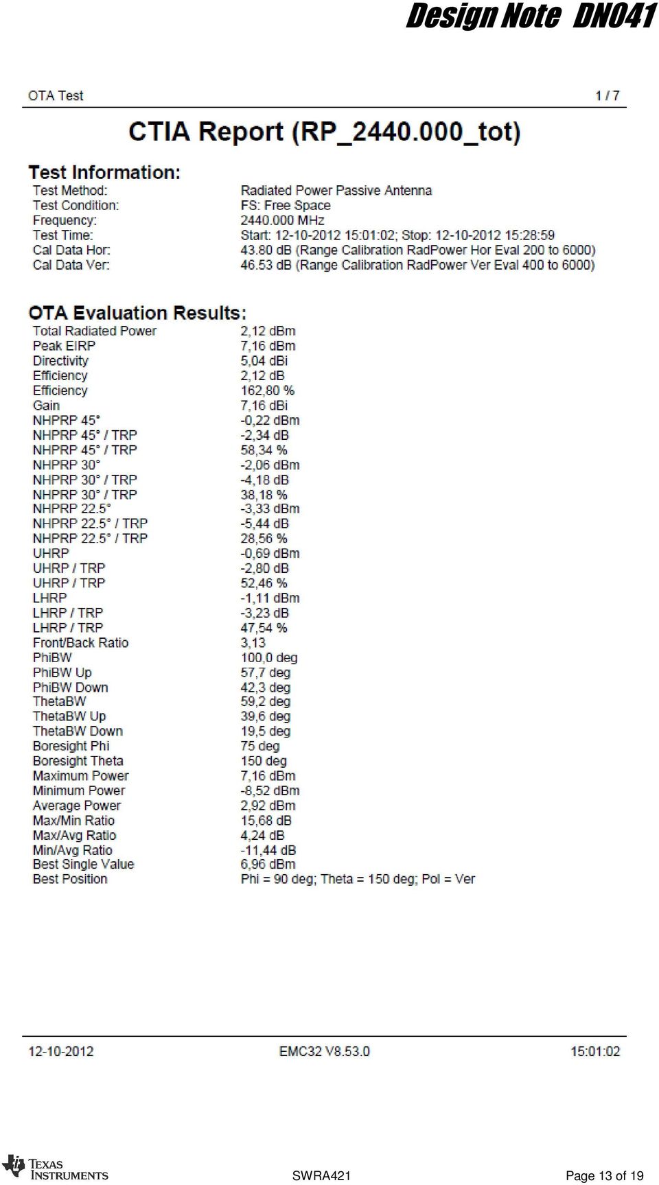
10 The most obvious observation is that the 2 nd harmonic level is more or less independent of the TRP and L values, but has a tendency to decrease with increasing capacitance to ground. This is most likely a result of the 2.7 pf cap being resonant close to the 2 nd harmonic, so the closer we get to 2.7 pf the better the decoupling/filtering. The 3 rd harmonic level seems to depend mostly on the carrier power, and since we want to get it down towards dbm to avoid strict duty cycle requirements from the FCC, we choose an inductance of 3.9 nh and a capacitance of 1.5 pf (which is equivalent to 0.75 pf in parallel with the inductor in the LC parallel resonant circuit). This gives us a safe level of the 2 nd harmonic, a 3 rd harmonic that is compliant with up to almost 50% duty cycle, and just above +2 dbm TRP. If we reduce the output power slightly, the 3 rd harmonic will pass FCC even with 100% duty cycle. TXPOWER = 0xF5 TXPOWER = 0xE5 TXPOWER = 0xD5 Sample TRP 2 nd 3 rd TRP 2 nd 3 rd TRP 2 nd 3 rd S S BTM BTM S S BTM BTM Table 4: TRP and Harmonics Levels with 3 Different Power Settings (TXPOWER = 0xF5, E5 and D5) The available power from CC2531 when using power setting 0xF5 is +4 dbm, which means that our measured TRP is less than 2 db short of the efficiency reference. This gives an efficiency of at least 100* = 63% even though this design has not been tuned for maximum TRP. The part numbers of the 3.9 nh inductor and 1.5pF capacitors are: GRM1555C1H1R5CZ01 (0402 capacitor with C0G/NP0 dielectric from Murata) LQG15HS3N3S02 (0402 multilayer chip inductor from Murata) A full measurement report on this antenna can be found in Appendix A: CTIA Report 8 Conclusion A half wave dipole can be an excellent antenna choice for low cost RF nodes. A simple 3- component filter is all that is needed to ensure regulatory compliance. The antenna designed in this Design Note has an efficiency of more than 63%, and a directivity of 5.04 dbi. SWRA421 Page 10 of 19

11 9 General Information 9.1 Document History Revision Date Description/Changes SWRA Initial release. SWRA421 Page 11 of 19

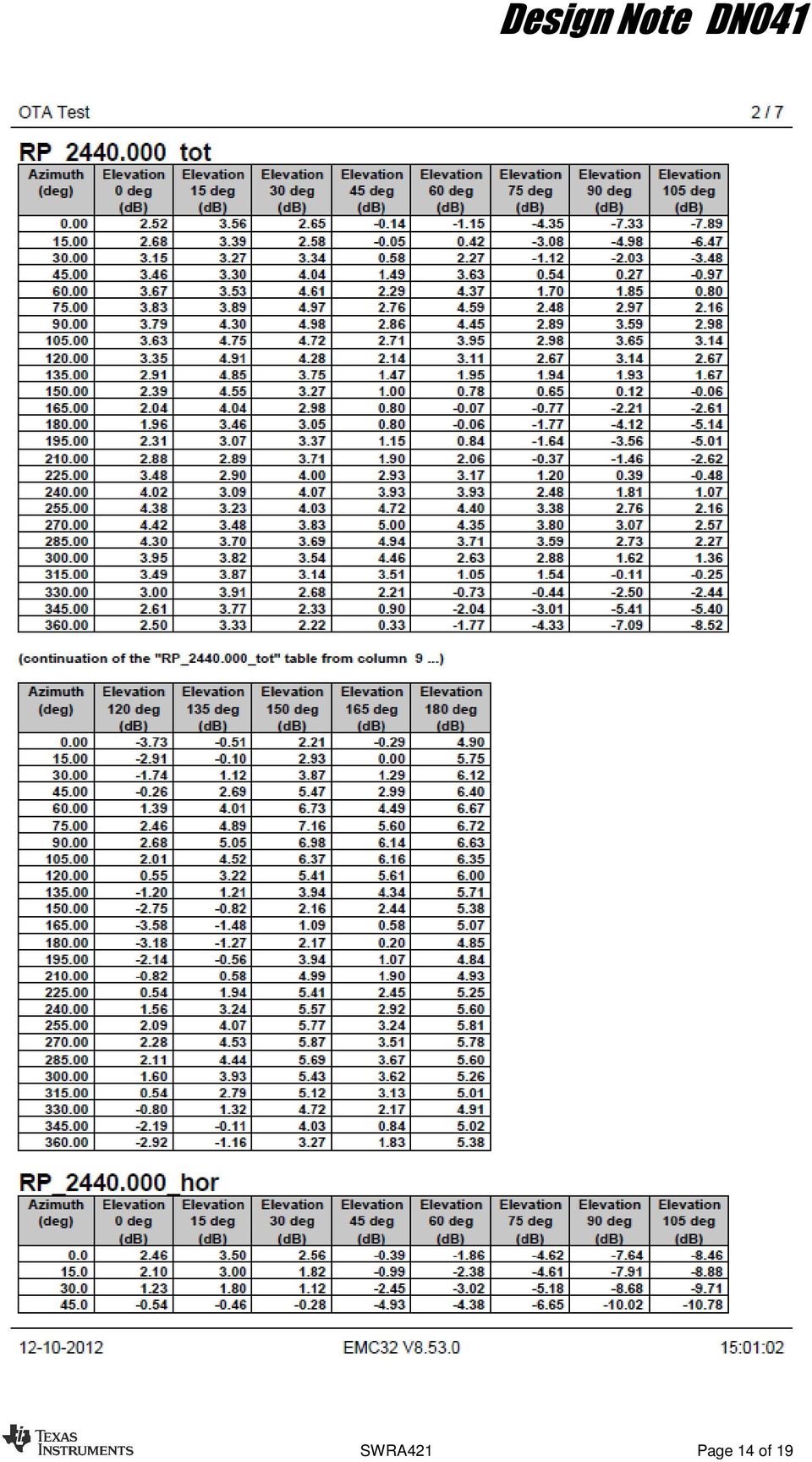
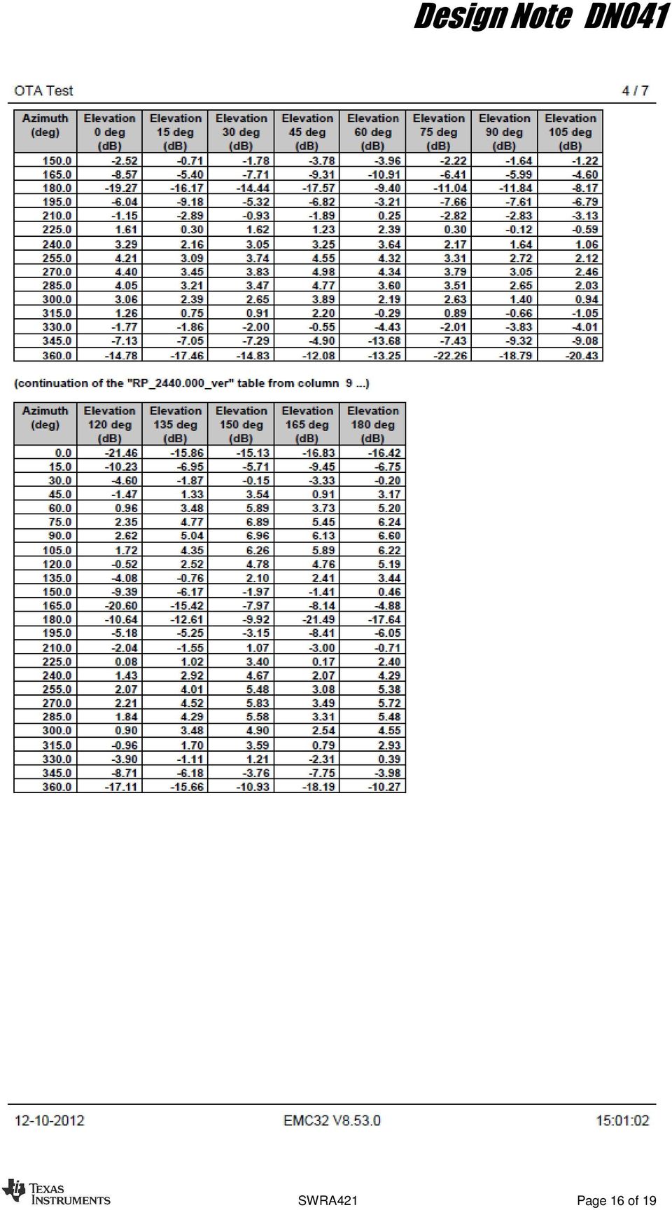
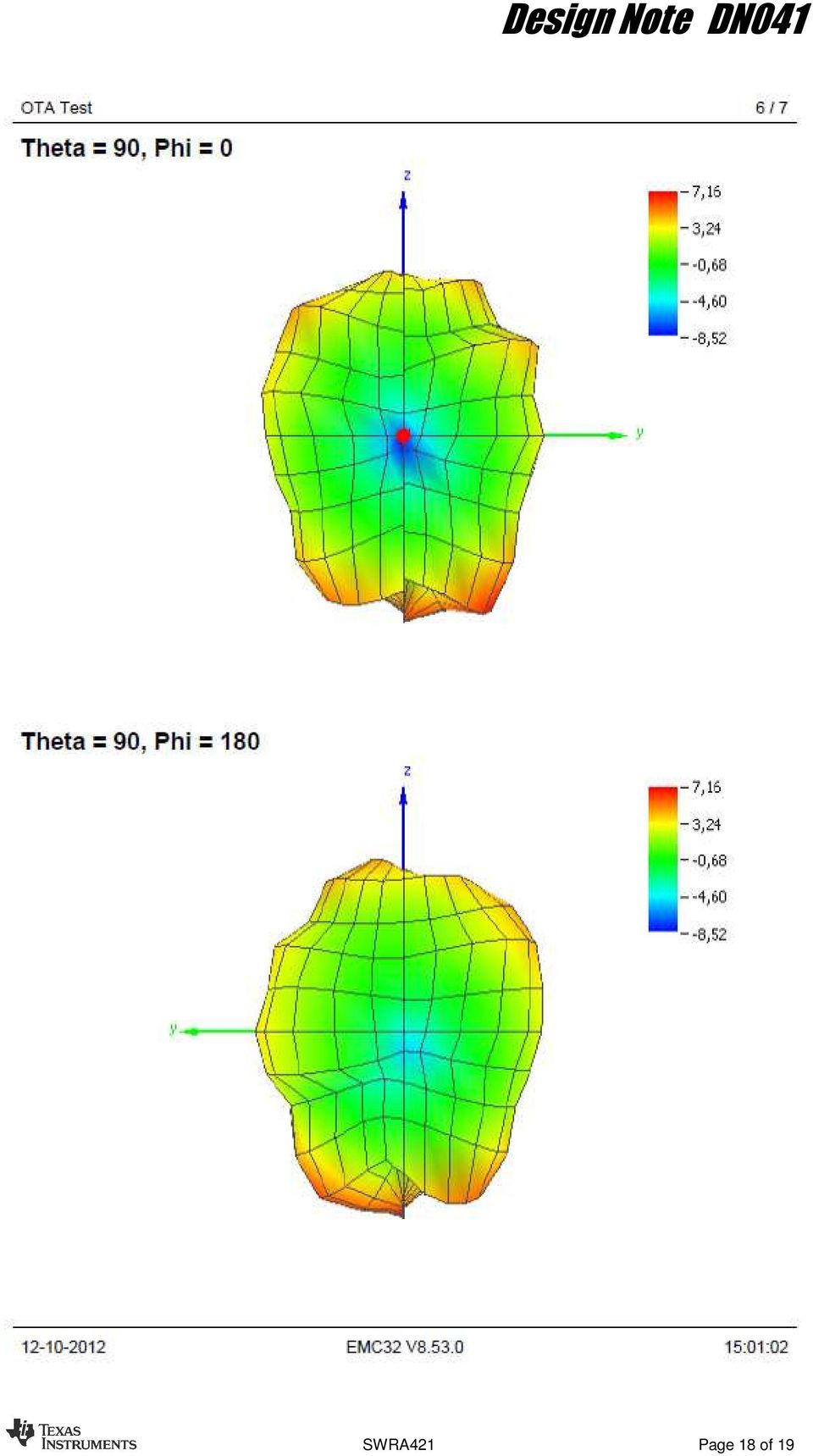
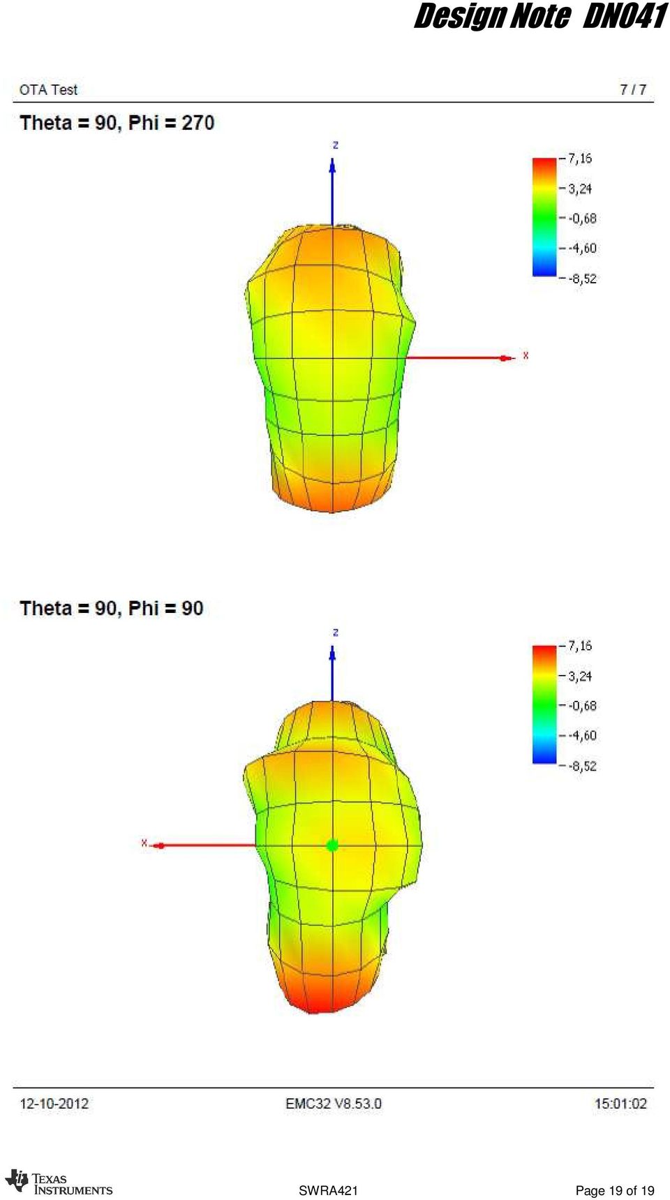
12 Appendix A: CTIA Report With the board placed in the XZ-plane as shown in Figure 12, the radiation diagram was measured in an antenna chamber. The reference level used to calculate efficiency and gain was 0 dbm, which means that 4 db needs to be subtracted from the gain given that the available power from CC2531 is 4 dbm. Z X Figure 12. Board Orientation During the Antenna Measurements SWRA421 Page 12 of 19

13 SWRA421 Page 13 of 19

14 SWRA421 Page 14 of 19

15 SWRA421 Page 15 of 19


16 SWRA421 Page 16 of 19
17 SWRA421 Page 17 of 19

18 SWRA421 Page 18 of 19
19 SWRA421 Page 19 of 19
20 IMPORTANT NOTICE Texas Instruments Incorporated and its subsidiaries (TI) reserve the right to make corrections, enhancements, improvements and other changes to its semiconductor products and services per JESD46, latest issue, and to discontinue any product or service per JESD48, latest issue. Buyers should obtain the latest relevant information before placing orders and should verify that such information is current and complete. All semiconductor products (also referred to herein as components ) are sold subject to TI s terms and conditions of sale supplied at the time of order acknowledgment. TI warrants performance of its components to the specifications applicable at the time of sale, in accordance with the warranty in TI s terms and conditions of sale of semiconductor products. Testing and other quality control techniques are used to the extent TI deems necessary to support this warranty. Except where mandated by applicable law, testing of all parameters of each component is not necessarily performed. TI assumes no liability for applications assistance or the design of Buyers products. Buyers are responsible for their products and applications using TI components. To minimize the risks associated with Buyers products and applications, Buyers should provide adequate design and operating safeguards. TI does not warrant or represent that any license, either express or implied, is granted under any patent right, copyright, mask work right, or other intellectual property right relating to any combination, machine, or process in which TI components or services are used. Information published by TI regarding third-party products or services does not constitute a license to use such products or services or a warranty or endorsement thereof. Use of such information may require a license from a third party under the patents or other intellectual property of the third party, or a license from TI under the patents or other intellectual property of TI. Reproduction of significant portions of TI information in TI data books or data sheets is permissible only if reproduction is without alteration and is accompanied by all associated warranties, conditions, limitations, and notices. TI is not responsible or liable for such altered documentation. Information of third parties may be subject to additional restrictions. Resale of TI components or services with statements different from or beyond the parameters stated by TI for that component or service voids all express and any implied warranties for the associated TI component or service and is an unfair and deceptive business practice. TI is not responsible or liable for any such statements. Buyer acknowledges and agrees that it is solely responsible for compliance with all legal, regulatory and safety-related requirements concerning its products, and any use of TI components in its applications, notwithstanding any applications-related information or support that may be provided by TI. Buyer represents and agrees that it has all the necessary expertise to create and implement safeguards which anticipate dangerous consequences of failures, monitor failures and their consequences, lessen the likelihood of failures that might cause harm and take appropriate remedial actions. Buyer will fully indemnify TI and its representatives against any damages arising out of the use of any TI components in safety-critical applications. In some cases, TI components may be promoted specifically to facilitate safety-related applications. With such components, TI s goal is to help enable customers to design and create their own end-product solutions that meet applicable functional safety standards and requirements. Nonetheless, such components are subject to these terms. No TI components are authorized for use in FDA Class III (or similar life-critical medical equipment) unless authorized officers of the parties have executed a special agreement specifically governing such use. Only those TI components which TI has specifically designated as military grade or enhanced plastic are designed and intended for use in military/aerospace applications or environments. Buyer acknowledges and agrees that any military or aerospace use of TI components which have not been so designated is solely at the Buyer's risk, and that Buyer is solely responsible for compliance with all legal and regulatory requirements in connection with such use. TI has specifically designated certain components as meeting ISO/TS16949 requirements, mainly for automotive use. In any case of use of non-designated products, TI will not be responsible for any failure to meet ISO/TS Products Applications Audio Automotive and Transportation Amplifiers amplifier.ti.com Communications and Telecom Data Converters dataconverter.ti.com Computers and Peripherals DLP Products Consumer Electronics DSP dsp.ti.com Energy and Lighting Clocks and Timers Industrial Interface interface.ti.com Medical Logic logic.ti.com Security Power Mgmt power.ti.com Space, Avionics and Defense Microcontrollers microcontroller.ti.com Video and Imaging RFID OMAP Applications Processors TI E2E Community e2e.ti.com Wireless Connectivity Mailing Address: Texas Instruments, Post Office Box , Dallas, Texas Copyright 2013, Texas Instruments Incorporated
 are sold subject to TI s terms and conditions of sale supplied at the time of order acknowledgment.")
Application Note AN107
 Murata Balun for CC253x and CC254x LFB182G45BG2D280 By Fredrik Kervel Keywords Balun LFB182G45BG2D280 CC253x CC254x CC257x CC85xx 1 Introduction Murata s LFB182G45BG2D280 integrated balun is specially
LM5030 LM5030 Application: DC - DC Converter Utilizing the Push-Pull Topology
 LM5030 LM5030 Application: DC - DC Converter Utilizing the Push-Pull Topology Literature Number: SNVA553 LM5030 Application DC DC Converter Utilizing the Push-Pull Topology 1 Push-Pull Topology D1 L +
AMC1100: Replacement of Input Main Sensing Transformer in Inverters with Isolated Amplifier
 Application Report SLAA552 August 2012 AMC1100: Replacement of Input Main Sensing Transformer in Inverters with Isolated Amplifier Ambreesh Tripathi and Harmeet Singh Analog/Digital Converters ABSTRACT
Design Note DN004. Folded Dipole Antenna for CC25xx By Audun Andersen. Keywords. 1 Introduction CC2500 CC2550 CC2510 CC2511
 Folded Dipole Antenna for CC25xx By Audun Andersen Keywords CC2500 CC2550 CC2510 CC2511 Folded Dipole PCB Antenna 2.4 GHz 1 Introduction This document describes a folded dipole PCB antenna design that
Design Note DN304. Cebal CCxxxx Development Tools USB Driver Installation Guide By Åsmund B. Bø. Keywords. 1 Introduction
 Cebal CCxxxx Development Tools USB Driver Installation Guide By Åsmund B. Bø Keywords Cebal Driver Windows x86 Windows x64 SmartRF Studio SmartRF Packet Sniffer SmartRF Flash Programmer SmartRF05EB SmartRF04EB
LM556 LM556 Dual Timer
 LM556 LM556 Dual Timer Literature Number: SNAS549 LM556 Dual Timer General Description The LM556 Dual timing circuit is a highly stable controller capable of producing accurate time delays or oscillation.
Data sheet acquired from Harris Semiconductor SCHS078C -- Revised October 2003
 Data sheet acquired from Harris Semiconductor SCHS078C -- Revised October 2003 The CD4521B types are supplied in 16-lead dual-in-line plastic packages (E suffix), 16-lead small-outline packages (M, M96,
LM709 LM709 Operational Amplifier
 LM709 LM709 Operational Amplifier Literature Number: SNOS659A LM709 Operational Amplifier General Description The LM709 series is a monolithic operational amplifier intended for general-purpose applications
54LS174,54LS175,DM54LS174,DM54LS175, DM74LS174,DM74LS175
 54LS174,54LS175,DM54LS174,DM54LS175, DM74LS174,DM74LS175 54LS174 DM54LS174 DM74LS174 54LS175 DM54LS175 DM74LS175 Hex/Quad D Flip-Flops with Clear Literature Number: SNOS290A 54LS174 DM54LS174 DM74LS174
Analysis of Power Supply Topologies for IGBT Gate Drivers in Industrial
 Application Report SLAA672 July 2015 Analysis of Power Supply Topologies for IGBT Gate Drivers in Industrial Sanjay Pithadia, N. Navaneeth Kumar ABSTRACT This application report explains different parameters
Providing Continuous Gate Drive Using a Charge Pump
 Application Report Philip Meyer and John Tucker... Power Management Products ABSTRACT Certain applications require that output voltage regulation be maintained when the input voltage is only slightly higher
Wireless Subwoofer TI Design Tests
 Wireless Subwoofer TI Design Tests This system design was tested for THD+N vs. frequency at 5 watts and 30 watts and THD+N vs. power at 00. Both the direct analog input and the wireless systems were tested.
APPLICATION NOTE BUILDING A QAM MODULATOR USING A GC2011 DIGITAL FILTER CHIP
 SLWA022 APPLICATION NOTE BUILDING A QAM MODULATOR USING A GC2011 DIGITAL CHIP October 6, 1994 1.0 INTRODUCTION This report describes how one can use the GC2011 Digital Filter chip to build digital modulators
Ultrasonic Sensing Basics for Liquid Level Sensing, Flow Sensing, and Fluid
 Application Report SNAA0A March 015 Revised June 015 Ultrasonic Sensing Basics for Liquid Level Sensing, Flow Sensing, and Fluid AmyLe ABSTRACT The need for accurate and reliable sensors is growing in
AN-1733 Load Transient Testing Simplified
 Application Report... ABSTRACT The load transient test may be the simplest diagnostic tool available to instantly analyze the loop stability of a system: the visual appearance of the output voltage as
Importing a SPICE NetList Into TINA9-TI
 Application Report Importing a SPICE NetList into TINA9-TI John Miller... Analog elab ABSTRACT This application note describes the procedure for importing an unencrypted SPICE netlist into TINA9-TI (available
LM388 LM388 1.5W Audio Power Amplifier
 LM388 LM388 1.5W Audio Power Amplifier Literature Number: SNOSBT8A LM388 1 5W Audio Power Amplifier General Description The LM388 is an audio amplifier designed for use in medium power consumer applications
Application Report. 1 Description of the Problem. Jeff Falin... PMP Portable Power Applications ABSTRACT
 Application Report SLVA255 September 2006 Minimizing Ringing at the Switch Node of a Boost Converter Jeff Falin... PMP Portable Power Applications ABSTRACT This application report explains how to use proper
AN-225 IC Temperature Sensor Provides Thermocouple Cold-Junction
 Application Report AN-225 IC Temperature Sensor Provides Thermocouple Cold-Junction... ABSTRACT Two circuits using the LM335 for thermocouple cold-junction compensation have been described. With a single
Multi-Transformer LED TV Power User Guide. Anderson Hsiao
 Multi-Transformer LED TV Power User Guide Anderson Hsiao Operation Range Input Range: 90Vac~264Vac 47Hz~63Hz Dimming Range: Reverse Signal 0V ~ 5V 100Hz ~200Hz 1%~100% Output Range :STBY-5V 20mA~1A 5V
Texas Instruments. FB PS LLC Test Report HVPS SYSTEM AND APPLICATION TEAM REVA
 Texas Instruments FB PS LLC Test Report HVPS SYSTEM AND APPLICATION TEAM REVA 12/05/2014 1 General 1.1 PURPOSE Provide the detailed data for evaluating and verifying the FB-PS-LLC. The FB-PS-LLC is a Full
AN-1963 IEEE 1588 Synchronization Over Standard Networks Using the
 Application Report AN-963 IEEE 588 Synchronization Over Standard Networks Using the... ABSTRACT This application report describes a method of synchronization that provides much more accurate synchronization
AN-311 Theory and Applications of Logarithmic Amplifiers
 Application Report... ABSTRACT A number of instrumentation applications can benefit from the use of logarithmic or exponential signal processing techniques. The design and use of logarithmic/exponential
White Paper on Decision of Make vs. Buy of ISM RF Module Written by Bruce Ulrich October 2006
 White Paper on Decision of Make vs. Buy of ISM RF Module Written by Bruce Ulrich October 2006 Abstract As companies implement wireless features into their portfolio, they may require new expertise to their
SDLS940A MARCH 1974 REVISED MARCH 1988. Copyright 1988, Texas Instruments Incorporated
 SN5490A, SN5492A, SN5493A, SN54LS90, SN54LS92, SN54LS93 SN7490A, SN7492A, SN7493A, SN74LS90, SN74LS92, SN74LS93 DECADE, DIVIDE-BY-TWELVE AND BINARY COUNTERS SDLS940A MARCH 1974 REVISED MARCH 1988 PRODUCTION
DS8907 DS8907 AM/FM Digital Phase-Locked Loop Frequency Synthesizer
 DS8907 DS8907 AM/FM Digital Phase-Locked Loop Frequency Synthesizer Literature Number: SNOSBR1A DS8907 AM FM Digital Phase-Locked Loop Frequency Synthesizer General Description The DS8907 is a PLL synthesizer
LM1851 LM1851 Ground Fault Interrupter
 LM1851 LM1851 Ground Fault Interrupter Literature Number: SNIS158 LM1851 Ground Fault Interrupter General Description The LM1851 is designed to provide ground fault protection for AC power outlets in consumer
DC/DC LED Lighting Developer s Kit Hardware
 Reference Guide The DC/DC LED lighting developer s kit provides a great way to learn and experiment by using a single MCU to accurately control a series of LED strings and efficiently control the power
AN-1900 LM3150 Evaluation Boards
 User's Guide 1 Introduction The LM3150 evaluation boards are designed to provide the design engineer with a fully functional power converter based on Constant On-Time with Emulated Ripple mode control
HF Antenna Cookbook. Technical Application Report. 11-08-26-001 March 2001. Radio Frequency Identification Systems
 HF Antenna Cookbook Technical Application Report 11-08-26-001 March 2001 Radio Frequency Identification Systems Contents Edition One March 2001... i About this Manual... ii Conventions... ii If You Need
LM138,LM338. LM138/LM338 5-Amp Adjustable Regulators. Literature Number: SNVS771A
 LM138,LM338 LM138/LM338 5-Amp Adjustable Regulators Literature Number: SNVS771A LM138/LM338 5-Amp Adjustable Regulators General Description The LM138 series of adjustable 3-terminal positive voltage regulators
AN-1862 Reducing Radiated Emissions in Ethernet 10/100 LAN Applications
 Application Report AN-1862 Reducing Radiated Emissions in Ethernet 10/100 LAN Applications... ABSTRACT This application report explains how Texas Instruments' PHYTER products help system designers to reduce
Calculating Gain for Audio Amplifiers
 Application eport SLOA105A October 003 evised September 005 Calculating Gain for Audio Amplifiers Audio Power Amplifiers ABSTACT This application report explains the different types of audio power amplifier
ZigBee Sensor Monitor SWRU157D 2008 Low-Power RF
 s e r ' s G u i d e User's Guide ZigBee Sensor Monitor SWRU157D 2008 Low-Power RF Contents ZIGBEE SENSOR MONITOR... 1 1. INTRODUCTION... 2 1.1. CC2530ZDK... 2 1.2. EZ430-RF2480... 2 2. INSTALLATION...
with Ultra-Fast Transient Response and High Light-Load Efficiency
 1 Adaptor 6-24V Optional N-FET Driver Ultra-Fast DPM Simplified Application Diagram Iin Ultra-Low Quiescent Current Enhanced Safety Features OCP, OVP, FET Short Support CPU Turbo Mode To System bq24715
SDLS068A DECEMBER 1972 REVISED OCTOBER 2001. Copyright 2001, Texas Instruments Incorporated
 SN54174, SN54175, SN54LS174, SN54LS175, SN54S174, SN54S175, SN74174, SN74175, SN74LS174, SN74LS175, SN74S174, SN74S175 PRODUCTION DATA information is current as of publication date. Products conform to
TrxEB RF PER Test Software Example. User s Guide SWRU296
 TrxEB RF PER Test Software Example User s Guide SWRU296 Table of Contents TABLE OF CONTENTS... 2 LIST OF FIGURES... 2 LIST OF TABLES... 3 1 INTRODUCTION... 4 2 ABOUT THIS MANUAL... 4 3 ACRONYMS AND ABBREVIATIONS...
TL081 TL081 Wide Bandwidth JFET Input Operational Amplifier
 TL081 TL081 Wide Bandwidth JFET Input Operational Amplifier Literature Number: SNOSBW6A TL081 Wide Bandwidth JFET Input Operational Amplifier General Description The TL081 is a low cost high speed JFET
AN-1405 DP83848 Single 10/100 Mb/s Ethernet Transceiver Reduced Media Independent Interface (RMII ) Mode
 Mode") Application Report SNLA076A October 2005 Revised April 2013 AN-1405 DP83848 Single 10/100 Mb/s Ethernet Transceiver Reduced Media... ABSTRACT This application report summarizes how a designer can take
Application Report SNLA076A October 2005 Revised April 2013 AN-1405 DP83848 Single 10/100 Mb/s Ethernet Transceiver Reduced Media... ABSTRACT This application report summarizes how a designer can take
Thumbus2300. User's Guide. 1 Introduction. 1.1 Features. 1.2 Kit Contents
 User's Guide SLUU399A April 2010 Revised March 2011 Thumbus2300 This users guide describes the function and operation of the Thumbus2300 evaluation module. A complete description, as well as schematic
Design Note DN002. Practical Sensitivity Testing By Morten Engjom. Keywords. 1 Introduction. Receiver Testing Sensitivity
 Practical Sensitivity Testing By Morten Engjom Keywords Receiver Testing Sensitivity PER (Packet Error Rate) BER (Bit Error Rate) 1 Introduction To properly evaluate the receiver part of a transceiver,
RF37S114 Tag-it HF-I Type 5 NFC, ISO/IEC 15693 Transponder, 4 mm 4 mm
 1 1 Product Folder Sample & Buy Technical Documents Tools & Software Support & Community RF37S114 SCBS907 NOVEMBER 2015 RF37S114 Tag-it HF-I Type 5 NFC, ISO/IEC 15693 Transponder, 4 mm 4 mm 1 Device Overview
TI and ibiquity Introduce Industry s Lowest Cost Single-Chip AM/FM and HD Radio Baseband John Gardner Digital Radio Marketing Manager
 TI and ibiquity Introduce Industry s Lowest Cost Single-Chip AM/FM and HD Radio Baseband John Gardner Digital Radio Marketing Manager SPRT328 HD Radio Products Planned Trunk mounted HD Radio receiver at
Filter Design in Thirty Seconds
 Application Report SLOA093 December 2001 Filter Design in Thirty Seconds Bruce Carter High Performance Analog ABSTRACT Need a filter fast? No theory, very little math just working filter designs, and in
Evaluating the complex configuration options of the Texas Instruments advanced fuel gauges can be
 User's Guide SLUU307A March 2008 Revised April 2008 bqeasy for Single Cell Impedance Track Devices Texas Instruments advanced fuel gauges, that employ the Impedance Track algorithm, offer an unmatched
AN-1826 Extending the Reach of a FPD-Link II Interface With Cable Drivers and Equalizers
 Application Report SNLA103A March 2008 Revised April 2013 AN-1826 Extending the Reach of a FPD-Link II Interface With Cable Drivers... ABSTRACT TI's family of embedded clock LVDS SER/DES (FPD-link II)
Using C to Access Data Stored in Program Memory on the TMS320C54x DSP
 Application Report SPRA177A August 2005 Using C to Access Data Stored in Program Memory on the TMS320C54x DSP David M. Alter DSP Applications - Semiconductor Group ABSTRACT Efficient utilization of available
Data sheet acquired from Harris Semiconductor SCHS067B Revised July 2003
 Data sheet acquired from Harris Semiconductor SCHS067B Revised July 2003 The CD4502B types are supplied in 16-lead hermetic dual-in-line ceramic packages (F3A suffix), 16-lead dual-in-line plastic packages
Application Report. 1 Introduction. 2 Resolution of an A-D Converter. 2.1 Signal-to-Noise Ratio (SNR) Harman Grewal... ABSTRACT
 Harman Grewal... ABSTRACT") Application Report SLAA323 JULY 2006 Oversampling the ADC12 for Higher Resolution Harman Grewal... ABSTRACT This application report describes the theory of oversampling to achieve resolutions greater than
Application Report SLAA323 JULY 2006 Oversampling the ADC12 for Higher Resolution Harman Grewal... ABSTRACT This application report describes the theory of oversampling to achieve resolutions greater than
CD4071B Quad 2-Input OR Gate CD4072B Dual 4-Input OR Gate CD4075B Triple 3-Input OR Gate
 Data sheet acquired from Harris Semiconductor SCHS056D Revised August 2003 CD4071B Quad 2-Input OR Gate CD4072B Dual 4-Input OR Gate CD4075B Triple 3-Input OR Gate CD4071B, CD4072B, and CD4075B OR gates
LMS8117A LMS8117A 1A Low-Dropout Linear Regulator
 LMS8117A LMS8117A 1A Low-Dropout Linear Regulator Literature Number: SNOS487E LMS8117A 1A Low-Dropout Linear Regulator General Description The LMS8117A is a series of low dropout voltage regulators with
Data sheet acquired from Harris Semiconductor SCHS049C Revised October 2003
 Data sheet acquired from Harris Semiconductor SCHS049C Revised October 2003 CD4060B consists of an oscillator section and 14 ripple-carry binary counter stages. The oscillator configuration allows design
Designing Gain and Offset in Thirty Seconds
 Application Report SLOA097 February 2002 Designing Gain and Offset in Thirty Seconds Bruce Carter High Performance Linear ABSTRACT This document discusses how to design an operational amplifier (op amp)
Data sheet acquired from Harris Semiconductor SCHS087D Revised October 2003
 Data sheet acquired from Harris Semiconductor SCHS087D Revised October 2003 The CD4555B and CD4556B types are supplied in 16-lead hermetic dual-in-line ceramic packages (F3A suffix), 16-lead dual-in-line
LM3444 MR16 Boost Reference Design for Non-Dimming & Dimming LED Applications
 Reference Design Lighting Power Products Longmont Design Center LM3444 MR16 Boost Reference Design for Non-Dimming & Dimming LED Applications Feb 13, 2012 Revision 3.0 NATIONAL SEMICONDUCTOR Page 1 of
ORDERING INFORMATION. TOP-SIDE MARKING PDIP N Tube SN74LS07N SN74LS07N PACKAGE. SOIC D Tape and reel SN74LS07DR
 The SN54LS07 and SN74LS17 are obsolete and are no longer supplied. Convert TTL Voltage Levels to MOS Levels High Sink-Current Capability Input Clamping Diodes Simplify System Design Open-Collector Driver
6 Output With 1 kω in Series Between the Output and Analyzer... 7 7 Output With RC Low-Pass Filter (1 kω and 4.7 nf) in Series Between the Output
 in Series Between the Output") Application Report SLAA313 December 26 Out-of-Band Noise Measurement Issues for Audio Codecs Greg Hupp... Data Acquisition Products ABSTRACT This report discusses the phenomenon of out-of-band noise, and
Application Report SLAA313 December 26 Out-of-Band Noise Measurement Issues for Audio Codecs Greg Hupp... Data Acquisition Products ABSTRACT This report discusses the phenomenon of out-of-band noise, and
High-voltage reinforced isolation:
 High-voltage reinforced isolation: Definitions and test methodologies Anant S Kamath Systems Engineer, Isolation, Interface Group Texas Instruments Kannan Soundarapandian Product Line Manager, Isolation,
MM58274C MM58274C Microprocessor Compatible Real Time Clock
 MM58274C MM58274C Microprocessor Compatible Real Time Clock Literature Number: SNOS618A MM58274C Microprocessor Compatible Real Time Clock General Description The MM58274C is fabricated using low threshold
µa7800 SERIES POSITIVE-VOLTAGE REGULATORS
 SLS056J MAY 976 REISED MAY 2003 3-Terminal Regulators Output Current up to.5 A Internal Thermal-Overload Protection High Power-Dissipation Capability Internal Short-Circuit Current Limiting Output Transistor
Data sheet acquired from Harris Semiconductor SCHS020C Revised October 2003
 Data sheet acquired from Harris Semiconductor SCHS020C Revised October 2003 The CD4009UB and CD4010B types are supplied in 16-lead hermetic dual-in-line ceramic packages (F3A suffix), 16-lead dual-in-line
TVP5146 SCART and OSD
 Application Report SLEA016 - October 2003 TVP5146 SCART and OSD HPA Digital Audio Video ABSTRACT The TVP5146 video decoder provides support for a SCART interface, which is commonly used in the European
LM5025,LM5026,LM5034 Operation and Benefits of Active-Clamp Forward Power Converters
 LM5025,LM5026,LM5034 Operation and Benefits of Active-Clamp Forward Power Converters Literature Number: SNVA591 POWER designer Expert tips, tricks, and techniques for powerful designs No. 108 Feature Article...1-7
August 2001 PMP Low Power SLVU051
 User s Guide August 2001 PMP Low Power SLVU051 IMPORTANT NOTICE Texas Instruments and its subsidiaries (TI) reserve the right to make changes to their products or to discontinue any product or service
 PACKAGE OPTION ADDENDUM www.ti.com 12-Jan-2006 PACKAGING INFORMATION Orderable Device Status (1) Package Type Package Drawing Pins Package Qty Eco Plan (2) Lead/Ball Finish MSL Peak Temp (3) 76005012A
PACKAGE OPTION ADDENDUM
 PACKAGE OPTION ADDENDUM www.ti.com 10-Jun-2014 PACKAGING INFORMATION Orderable Device Status (1) Package Type Package Drawing Pins Package Qty Eco Plan (2) Lead/Ball Finish (6) MSL Peak Temp (3) Op Temp
Optical Implementation Using IEEE-1394.b
 Application Report SGZA001A - March 2004 Optical Implementation Using IEEE-1394.b David Rekieta IEEE-1394 Products ABSTRACT IEEE Std 1394b-2002 specification allows the use of optical media for longer
Choosing Inductors and Capacitors for DC/DC Converters
 Application Report SLVA157 February 2004 Choosing Inductors and Capacitors for DC/DC Converters Christophe Vaucourt ABSTRACT Wireless handsets, PDAs, and other portable electronic devices continue to shrink
How To Design An Ism Band Antenna For 915Mhz/2.4Ghz Ism Bands On A Pbbb (Bcm) Board
 Board") APPLICATION NOTE Features AT09567: ISM Band PCB Antenna Reference Design Atmel Wireless Compact PCB antennas for 915MHz and 2.4GHz ISM bands Easy to integrate Altium design files and gerber files Return
APPLICATION NOTE Features AT09567: ISM Band PCB Antenna Reference Design Atmel Wireless Compact PCB antennas for 915MHz and 2.4GHz ISM bands Easy to integrate Altium design files and gerber files Return
Demystifying digital signal processing (DSP) programming: The ease in realizing implementations with TI DSPs
 programming: The ease in realizing implementations with TI DSPs") Demystifying digital signal processing (DSP) programming: The ease in realizing implementations with TI DSPs Todd Hahn Software Development Manager Jonathan Humphreys Software Senior Member Technical Staff
Demystifying digital signal processing (DSP) programming: The ease in realizing implementations with TI DSPs Todd Hahn Software Development Manager Jonathan Humphreys Software Senior Member Technical Staff
CLC012 CLC012 Adaptive Cable Equalizer for ITU-T G.703 Data Recovery
 CLC012 Adaptive Cable Equalizer for ITU-T G.703 Data Recovery Literature Number: SNLS032D OBSOLETE September 21, 2011 Adaptive Cable Equalizer for ITU-T G.703 Data Recovery General Description National's
TRF7960 Evaluation Module ISO 15693 Host Commands
 TRF7960 Evaluation Module ISO 15693 Host Commands Literature number: 11-06-26-009 Date: April 2008 RFID This page left deliberately blank Contents Contents... 3 Edition 1 April 2008... 5 About this Manual...6
TI Designs Precision: Verified Design Comparator with Hysteresis Reference Design
 TI Designs Precision: Verified Design Comparator with Hysteresis Reference Design Art Kay, Timothy Claycomb TI Designs Precision TI Designs Precision are analog solutions created by TI s analog experts.
Smart Codec Features in TMS320DM365
 Application Report Naveen Srinivasamurthy, Mahant Siddaramanna and Ritesh Rajore... MMCodecs ABSTRACT You will significantly enhance video encoder quality by incorporating external input/feedback from
Latch-Up. White Paper SCAA124 April 2015. Marty Johnson, Roger Cline, Scott Ward, Joe Schichl
 White Paper Marty Johnson, Roger Cline, Scott Ward, Joe Schichl ABSTRACT This document describes and discusses the topic of CMOS ranging from theory to testing of products. The recently proposed modifications
 PACKAGE OPTION ADDENDUM www.ti.com 12-Jan-2006 PACKAGING INFORMATION Orderable Device Status (1) Package Type Package Drawing Pins Package Qty Eco Plan (2) Lead/Ball Finish MSL Peak Temp (3) 5962-9557401QCA
Transcoding with TI s DaVinci Technology Drives Video Market Evolution
 W H I T E P A P E R By J.B. Fowler, SoC Product Marketing Manager Texas Instruments Transcoding with TI s DaVinci Technology Drives Video Market Evolution Executive Summary As the accelerating digital
Application Report. HIgh-Speed and RF. Matthew Loy, Raju Karingattil, Louis Williams - Editors... ABSTRACT
 Application Report SWRA048 May 2005 ISM-Band and Short Range Device Regulatory Compliance Overview Matthew Loy, Raju Karingattil, Louis Williams - Editors... HIgh-Speed and RF ABSTRACT This application
LM2900,LM3301,LM3900. LM2900/LM3900/LM3301 Quad Amplifiers. Literature Number: SNOSBV6
 LM2900,LM3301,LM3900 LM2900/LM3900/LM3301 Quad Amplifiers Literature Number: SNOSBV6 LM2900/LM3900/LM3301 Quad Amplifiers General Description The LM2900 series consists of four independent, dual input,
LM2747,LM3100,LM5035 Synchronous Rectification in High-Performance Power Converter Design
 LM2747,LM3100,LM5035 Synchronous Rectification in High-Performance Power Converter Design Literature Number: SNVA595 POWER designer Expert tips, tricks, and techniques for powerful designs No. 112 Feature
The main goal of this tutorial is to get familiar with SmartRF Studio 7: Learn how it works and what it can do.
 1 The main goal of this tutorial is to get familiar with SmartRF Studio 7: Learn how it works and what it can do. The tutorial will walk you through some exercises showing how to use SmartRF Studio 7 in
Using Code Coverage and Multi-event Profiler in Code Composer Studio v2.3 for Robustness and Efficiency Analyses
 Application Report SPRA868A April 2004 Using Code Coverage and Multi-event Profiler in Code Composer Studio v2.3 for Robustness and Efficiency Analyses Amit Rangari, N.Pradeep Software Development Systems
How To Close The Loop On A Fully Differential Op Amp
 Application Report SLOA099 - May 2002 Fully Differential Op Amps Made Easy Bruce Carter High Performance Linear ABSTRACT Fully differential op amps may be unfamiliar to some designers. This application
Current-Transformer Phase-Shift Compensation and Calibration
 Application Report SLAA122 February 2001 Current-Transformer Phase-Shift Compensation and Calibration Kes Tam Mixed Signal Products ABSTRACT This application report demonstrates a digital technique to
Pressure Transducer to ADC Application
 Application Report SLOA05 October 2000 Pressure Transducer to ADC Application John Bishop ABSTRACT Advanced Analog Products/OpAmp Applications A range of bridgetype transducers can measure numerous process
SN54165, SN54LS165A, SN74165, SN74LS165A PARALLEL-LOAD 8-BIT SHIFT REGISTERS
 The SN54165 and SN74165 devices SN54165, SN54LS165A, SN74165, SN74LS165A PRODUCTION DATA information is current as of publication date. Products conform to specifications per the terms of Texas Instruments
AN-1651 Keeping Up with the Expanding Demands of High-Performance
 Application Report AN-1651 Keeping Up with the Expanding Demands of High-Performance... ABSTRACT This application report provides several design examples of high-performance applications using the /LM4562
LM3203,LM3204,LM3205 Optimizing RF Power Amplifier System Efficiency Using DC-DC Converters
 LM3203,LM3204,LM3205 Optimizing RF Power Amplifier System Efficiency Using DC-DC Converters Literature Number: SNVA593 POWER designer Expert tips, tricks, and techniques for powerful designs No. 110 Feature
DS15BA101,DS15EA101,DS25BR110
 DS15BA101,DS15EA101,DS25BR110 Extending the Signal Path Over Data Transmission Lines Using LVDS Signal Conditioning Literature Number: SNLA209 SIGNAL PATH designer Tips, tricks, and techniques from the
Application Note SAW-Components
 Application Note SAW-Components Principles of SAWR-stabilized oscillators and transmitters. App: Note #1 This application note describes the physical principle of SAW-stabilized oscillator. Oscillator
RFID Receiver Antenna Project for 13.56 Mhz Band
 RFID Receiver Antenna Project for 13.56 Mhz Band Fatih Eken TE 401 Microwave Course Term Project, Fall 2004 Supervised by Asst. Prof. İbrahim Tekin Telecommunication Program in Faculty of Engineering and
Application Note AN068
 Application Note AN068 Adapting TI LPRF Reference Designs for Layer Stacking By Rea Schmid Keywords Board Stacking for RF Design VSWR changes with Stacking Bandwidth and Layer Stacking PCB for CC25xx Devices
Simulation and Design of Printed Circuit Boards Utilizing Novel Embedded Capacitance Material
 Simulation and Design of Printed Circuit Boards Utilizing Novel Embedded Capacitance Material Yu Xuequan, Yan Hang, Zhang Gezi, Wang Haisan Huawei Technologies Co., Ltd Lujiazui Subpark, Pudong Software
LMC835 LMC835 Digital Controlled Graphic Equalizer
 LMC835 LMC835 Digital Controlled Graphic Equalizer Literature Number: SNOSBP5 LMC835 Digital Controlled Graphic Equalizer General Description The LMC835 is a monolithic digitally-controlled graphic equalizer
1OE 3B NC 3B V GND ORDERING INFORMATION. QFN RGY Tape and reel SN74CBT3125RGYR CU125. SOIC D Tape and reel SN74CBT3125DR
 SN74CBT3125 QUADRUPLE FET BUS SWITCH SCDS021I MAY 1995 REVISED SEPTEMBER 2002 Standard 125-Type Pinout (D, DB, DGV, and PW Packages) 5-Ω Switch Connection Between Two Ports TTL-Compatible Input Levels
800VA Pure Sine Wave Inverter s Reference Design
 Application Report SLAA602 June 2013 800VA Pure Sine Wave Inverter s Reference Design Sanjay Dixit, Ambreesh Tripathi, Vikas Chola High Performance Isolated Power ABSTRACT This application note describes
AVR2006: Design and characterization of the Radio Controller Board's 2.4GHz PCB Antenna. Application Note. Features.
 AVR26: Design and characterization of the Radio Controller Board's 2.4GHz PCB Antenna Features Radiation pattern Impedance measurements WIPL design files NEC model Application Note 1 Introduction This
Signal Conditioning Piezoelectric Sensors
 Application Report SLOA033A - September 2000 Signal Conditioning Piezoelectric Sensors James Karki Mixed Signal Products ABSTRACT Piezoelectric elements are used to construct transducers for a vast number
VJ 6040 Mobile Digital TV UHF Antenna Evaluation Board
 VISHAY VITRAMON Multilayer Chip Capacitors Application Note GENERAL is a multilayer ceramic chip antenna designed for receiving mobile digital TV transmissions in the UHF band. The target application for
Impedance Matching and Matching Networks. Valentin Todorow, December, 2009
 Impedance Matching and Matching Networks Valentin Todorow, December, 2009 RF for Plasma Processing - Definition of RF What is RF? The IEEE Standard Dictionary of Electrical and Electronics Terms defines