SOLAR BOOST 2000E 25AMP 12VDC MAXIMUM POWER POINT TRACKING PHOTOVOLTAIC CHARGE CONTROLLER INSTALLATION AND OPERATION MANUAL
|
|
|
- Wilfrid Banks
- 7 years ago
- Views:
Transcription
1 SOLAR BOOST 2000E 25AMP 12VDC MAXIMUM POWER POINT TRACKING PHOTOVOLTAIC CHARGE CONTROLLER INSTALLATION AND OPERATION MANUAL THIS MANUAL INCLUDES IMPORTANT SAFETY INSTRUCTIONS FOR MODEL SB2000E SAVE THESE INSTRUCTIONS. COVERED UNDER ONE OR MORE OF THE FOLLOWING US PATENTS 6,111,391 Blue Sky Energy, Inc H

2 TABLE OF CONTENTS IMPORTANT SAFETY INSTRUCTIONS... 2 PRODUCT DESCRIPTION... 3 Part Numbers and Options... 3 OPERATION... 3 Charge Control... 4 Charge Status Indicator... 3 Battery Level Graphic... 4 Equalization... 4 Current Limit... 4 Optional Temperature Compensation... 5 Maximum Power Point Tracking (MPPT)... 5 INSTALLATION... 5 Electrostatic Handling Precautions... 5 Selecting PV Modules... 6 Temperature Compensation... 6 Battery and PV Wiring... 6 Setting Charge Voltage... 7 Maximum Power Voltage... 7 Optimizing MPPT... 7 TROUBLESHOOTING GUIDE SPECIFICATIONS FIVE YEAR LIMITED WARRANTY TABLES AND FIGURES Table 1 Charge Status Indicator... 3 Table 2 Maximum Conductor Length - 3% Voltage Drop... 7 Figure 1 Front Panel and Remote Display Indicators... 4 Figure 2 Factory Charge Voltage Setpoint -vs.- Battery Temperature... 5 Figure 3 Setup and Wiring Diagram... 7 Figure 4 Mounting Template

3 IMPORTANT SAFETY INSTRUCTIONS This manual contains important instructions for Model SB2000E SAVE THESE INSTRUCTIONS Installation and Operation Manual 1. Refer installation and servicing to qualified service personnel. High voltage is present inside unit. Incorrect installation or use may result in risk of electric shock or fire. No user serviceable parts in this unit. 2. To reduce the risk of electric shock, fire or personal injury, the following symbols are placed throughout this manual to indicate dangerous conditions, or important safety or operational instructions. WARNING CAUTION IMPORTANT Indicates dangerous conditions or electric shock potential. Use extreme caution. Indicates items critical to safe installation or operation of the unit. Follow these instructions closely for proper operation of the unit 3. PERSONAL PRECAUTIONS a) Working in the vicinity of lead-acid batteries is dangerous. Batteries produce explosive gasses during normal operation. b) To reduce risk of battery explosion, follow these instructions and those published by battery manufacturer and manufacturer of any equipment you intend to use in vicinity of battery. c) Someone should be within range of your voice or close enough to come to your aid when you work near a lead-acid battery. d) Have plenty of fresh water and soap nearby in case battery acid contacts skin, clothing or eyes. e) Wear complete eye protection and clothing protection. Avoid touching eyes while working near battery. f) If battery acid contacts skin or clothing, wash immediately with soap and water. If acid enters eye, immediately flood eye with running cold water for at least 15 minutes and get medical attention immediately. g) NEVER SMOKE or allow a spark or flame in vicinity of battery. h) Be extra cautious to reduce risk of dropping metal tool onto battery. It might spark or short circuit battery or other electrical part that may cause explosion. i) Remove personal metal items such as rings, bracelets and watches when working with a lead-acid battery. A lead-acid battery can produce a short circuit current high enough to weld a ring or the like to metal, causing a severe burn. j) Remove all sources of power, photovoltaic and battery before servicing or installing. 4. CHARGER LOCATION & INSTALLATION a) This unit is designed to charge 12V (6 cell) flooded or sealed type lead-acid chemistry batteries within the range of 10 to 10,000 amp-hours. Follow battery manufacturers charging recommendations when considering this unit for use with other battery chemistry. b) This unit employs components that tend to produce arcs or sparks. NEVER install in battery compartment or in the presence of explosive gases. c) This unit must be installed and wired in accordance with National Electrical Code, ANSI/NFPA 70. d) Over current protection for the battery must be provided externally. To reduce the risk of fire, connect to a circuit provided with 30 amperes maximum branch-circuit over current protection in accordance with National Electrical Code, ANSI/NFPA 70. e) Insure that unit is properly configured for the battery being charged. f) This unit is not water tight. Do not expose to rain, snow or excessive moisture. g) Insure all terminating connections are clean and tight. Battery, PV and battery temperature sensor terminals are to be tightened to 9 in-lb (1 nm). h) Do not connect to a PV array capable of producing greater than 20 amperes of short circuit current (ISC) or 24V of open circuit voltage STC. i) This unit is not provided with a GFDI (ground-fault detector/interrupter) device and must be used with an external GFDI device as required by Article 690 of National Electrical Code for the installation location. 5. PREPARING TO CHARGE a) Never charge a frozen battery. b) Be sure battery is mounted in a well ventilated compartment. c) Add distilled water in each cell of a lead-acid battery until battery acid reaches level specified by battery manufacturer. 2

4 PRODUCT DESCRIPTION Solar Boost 2000E is a 25 amp 12 volt Maximum Power Point Tracking (MPPT) photovoltaic (PV) battery charge controller with built in digital display. Through the use of patented MPPT technology the 2000E can increase charge current up to 30% or more compared to conventional controllers. The 2000E s sophisticated charge control system improves battery performance and life while minimizing battery maintenance. The unit is fully protected against voltage transients, over temperature, over current, reverse battery and reverse PV connections. An automatic current limit feature allows use of the full 25 amp capability without worrying about overload or nuisance fuse blow from excessive current. An environmentally sealed high current high reliability relay is used to disconnect the PV array at night to prevent unwanted current drain. PART NUMBERS AND OPTIONS SB2000E... Solar Boost 2000E charge controller Optional battery temperature sensor Optional wall mount box, black powder coated steel OPERATION Charge control and MPPT current boost operations are fully automatic. Charge turns on whenever the PV array is capable of producing approximately 0.15 amps 14 volts. Note that there must be a battery in the system with a minimum voltage of 9 volts or greater for the 2000E to operate. Electronic current limit prevents the possibility of overload by limiting output current to 25 amps regardless of available PV input current or input power. The highly accurate digital display consumes very little power and is always on and available for use. As shown in Figure 1, the display can be selected to show Solar Panel Current, Output Charge Current or Battery Voltage. Solar Panel Current displays current in amps flowing from the PV array to the 2000E, whereas Output Charge Current displays current in amps flowing from the 2000E to the battery. When MPPT current boost is functioning, Output Charge Current will be greater than Solar Panel Current. If operating conditions are such extra power is not available from the PV array and MPPT current boost is unable to operate, Output Charge Current may show 0.1 amps less than Solar Panel Current. This is normal as the 2000E consumes approximately amps to operate when PV charge is on. When PV charge is off, standby current consumption is quite low at approximately amps. Battery Voltage is measured at the 2000E s battery terminals. Although the measurement system is highly accurate, displayed voltage may be somewhat higher than actual battery terminal voltage when high charge current is being delivered to the battery. This is due to voltage drop in the wires between the 2000E and battery. Error during charge can be minimized by using large low resistance wiring. CHARGE CONTROL The 2000E operates on battery power, not PV power. A battery must be connected with a minimum voltage of 9 volts for the unit to operate. The 2000E provides a two stage charging process, Bulk and Constant Voltage. A third manually actuated Equalize mode is also available. The 2000E will be in Bulk charge when battery voltage is below the charge voltage setpoint (factory set to 14.0 volts). During Bulk the 2000E delivers as much charge current as possible to rapidly recharge the battery and drive battery voltage up to the charge voltage setpoint. Once the battery recovers sufficient charge for battery voltage to rise to the charge voltage setpoint, both PV current and output charge current are reduced as necessary to control battery voltage at the charge voltage setpoint. CHARGE STATUS INDICATOR A Charge Status indicator LED is provided on the 2000E panel. For small scale solar electric systems an excellent indication of a highly charged battery is when the 2000E is able to hold the battery at the desired charge voltage setpoint. These systems usually consist of watts of PV power, and charge a battery bank in the range of perhaps amp-hours. With sufficient PV power and the battery under light load so that there is at least 2 amps of net charge current per 100 amp-hours of battery capacity, the system will show the battery to be charged when the battery is greater than approximately 90 95% full. When the Charge Status LED blinks showing the 2000E to be in the constant voltage mode, the battery is considered charged. If PV power generation is too low and/or load current is too high for there to be at least 2 amps of net charge current available per 100 amp-hours of battery capacity the Solar Boost 2000E may be unable to hold battery voltage at the desired charge voltage setpoint. This will cause a discharged condition to be displayed even though the battery may be highly charged. A charged condition will again be displayed if sufficient net charge current becomes available and the battery is indeed charged. A smaller battery and/or larger PV array will tend to show a charged condition sooner. CHARGE STATUS INDICATOR CHARGE STATUS INDICATOR CHARGE MODE APPROXIMATE CHARGE LEVEL OFF CHARGE OFF CONTINUOUSLY ON BULK LESS THAN 90% FULL BLINKING 2 SEC ON / 2 SEC OFF CONSTANT VOLTAGE GREATER THAN 90% FULL RAPID BLINKING 0.2 SEC ON / 0.2 SEC OFF EQUALIZE TABLE 1 3

5 Installation and Operation Manual The 2000E front panel serves as a heat sink for power control devices. It is normal for the front panel to be quite warm to the touch during operation while delivering high charge current. PANEL LAYOUT BATTERY LEVEL GRAPHIC Figure 1 The 2000E also provides a battery level graphic on the front panel which indicates approximate battery level versus battery voltage. The indication covers a fairly wide range of voltage because at a given state of charge battery voltage can vary significantly depending on whether the battery is being charged, is at rest, or is being discharged under load. A higher voltage is generally better than a lower voltage. A battery being charged will typically range in voltage from about 12.5 volts after charge begins to perhaps 14.0 volts or greater when the battery is highly charged. Once charge stops and the battery is delivering power to a load voltage will drop which is normal and typically ranges between about 12.6 volts when the battery is full down to about 12.2 volts when the battery is about 50% discharged. Most battery manufacturers recommend not discharging below 50% DOD (depth of discharge) to promote improved battery performance and life. Battery voltage will continue to fall as the battery is further discharged. Note that the voltage during discharge will tend to be higher under light load and lower under heavy load. NEVER allow battery voltage to drop below 10.0 volts. EQUALIZATION WARNING: Not all batteries can be safely equalized. Equalization should be performed only on vented liquid electrolyte lead-acid batteries. Always follow battery manufacturers recommendations pertaining to equalization. Equalization applies a relatively high voltage producing significant battery gassing. Disconnect equipment that cannot tolerate the high equalization voltage which is temperature compensated. The 2000E equalization function is fully manual and an operator should always plan and monitor the process. Equalization is essentially a controlled over charge and should only be performed on vented liquid electrolyte lead-acid batteries. Repeated charge/discharge cycles can lead to an imbalance in the specific gravity and state of charge of individual battery cells. Equalization brings all battery cells up to the same specific gravity, and eliminates electrolyte stratification by heavily gassing the battery. Periodic equalization per the battery manufacturers recommendations will improve battery performance and life. A minimum net charge current of approximately 3.5 amps per 100 amp-hours of battery capacity is required for the battery reach the equalization voltage. Battery voltage setpoint during equalization will be the present charge voltage setpoint plus 1.2 volts or 15.2 volts for the factory calibrated charge voltage setpoint of 14.0 volts. Note that with temperature compensation, the equalization voltage can be quite high at cool temperatures. The operator should disconnect equipment that may not tolerate the high equalization voltage applied to the battery. As shown in Figure 1, the blue equalization push-button is located on the 2000E panel. Equalization is enabled when the push-button is in, and the Charge Status LED blinks rapidly. Always follow the battery manufacturers recommendations pertaining to equalization. Equalization is normally conducted approximately once per month, with the battery held at the equalization voltage for a period of approximately two hours. It is best to equalize a battery that is already fully charged so that the desired equalization voltage is reached quickly. Following the desired equalization period, the equalization cycle is terminated and normal charge operation is resumed by again pressing the equalization push-button. The battery should then be topped off with distilled water per the battery manufacturers recommendations. CURRENT LIMIT If PV input power is high enough to produce more than 25 amps of output current, the 2000E will automatically prevent output current from exceeding 25 amps to prevent overload or nuisance fuse blow. 4

6 OPTIONAL TEMPERATURE COMPENSATION The charge voltage required by flooded or sealed (AGM or GEL) lead-acid chemistry batteries changes with battery temperature. Temperature compensation of charge voltage leads to improved battery performance and life, and decreased battery maintenance. Automatic temperature compensation can be provided using the optional battery temperature sensor p/n Most 12 volt lead-acid chemistry batteries require a compensation characteristic of 30.0 millivolts/ C ( 5.00mV/ C/cell). The graph of Figure 2 shows charge voltage setpoint vs. battery temperature for the factory setting of F and the compensation characteristic of 30.0 millivolts/ C. As described in the installation section the 2000E can also provide a 20.0 millivolts/ C compensation characteristic required for 10 cell NiCd batteries and some GEL or AGM lead-acid chemistry batteries. FACTORY DEFAULT CHARGE VOLTAGE SETPOINT -VS.- BATTERY TEMPERATURE MAXIMUM POWER POINT TRACKING (MPPT) FIGURE 2 Patented MPPT technology can extract more power and increase charge current up to 30% or more compared to conventional charge controllers. The principal operating conditions which affect current boost performance are PV array temperature and battery voltage. At constant solar intensity, available PV voltage and power increase as PV temperature decreases but it takes an MPPT controller to access this extra power. When PV voltage is sufficiently high in Bulk for MPPT to operate, a constant power output is delivered to the battery. Since output power is constant a decrease in battery voltage produces a further increase in charge current. This means that the 2000E provides the greatest charge current increase when you need it most, in cold weather with a discharged battery. In cool comfortable temperatures most systems see about 10 20% increase. Charge current increase can go to zero in hot temperatures, whereas charge current increase can easily exceed 30% with a discharged battery in near freezing temperatures. For a more complete MPPT description see INSTALLATION WARNING: Read, understand and follow the Important Safety Instructions in the beginning of this manual before proceeding. This unit must be installed and wired in accordance with National Electrical Code, ANSI/NFPA 70. Over current protection must be provided externally. To reduce the risk of fire, connect to a circuit provided with 30 amp maximum branch-circuit over current protection in accordance with National Electrical Code, ANSI/NFPA 70. Do not connect a PV array capable of delivering greater than 20 amps of short circuit current ISC at STC. Do not connect BAT and PV together external to the unit or improper operation or damage will result. Terminal block connections accept #20 10 AWG wire and are to be tightened to 9 in-lb (1 nm). The front panel serves as a heat sink for power control devices and requires free air circulation for cooling. Do not enclose the front panel behind a tight fitting door or otherwise substantially restrict air flow. Figure 3 shows generalized connections only and is not intended to show all wiring, circuit protection and safety requirements for a photovoltaic or DC battery electrical system. CAUTION: The unit is protected against reverse battery and PV polarity, and swapped PV and battery connections, but will be damaged by reverse battery to the PV terminals. Transient voltage protection is provided, but steady state voltage in excess of 30VDC on the battery or PV terminals will damage the unit. The unit is not water tight and must be installed in an area free from rain, snow or excessive moisture. Damage due to improper installation, corrosion, or adjustments or connections other than those shown in Figure 3 void the limited warranty. ELECTROSTATIC HANDLING PRECAUTIONS All electronic circuits may be damaged by static electricity. To minimize the likelihood of electrostatic damage, discharge yourself by touching a water faucet or other electrical ground prior to handling the 2000E and avoid touching components on the circuit board. The risk of electrostatic damage is highest when relative humidity is below 40%. 5
. The graph of Figure 2 shows charge voltage setpoint vs.")
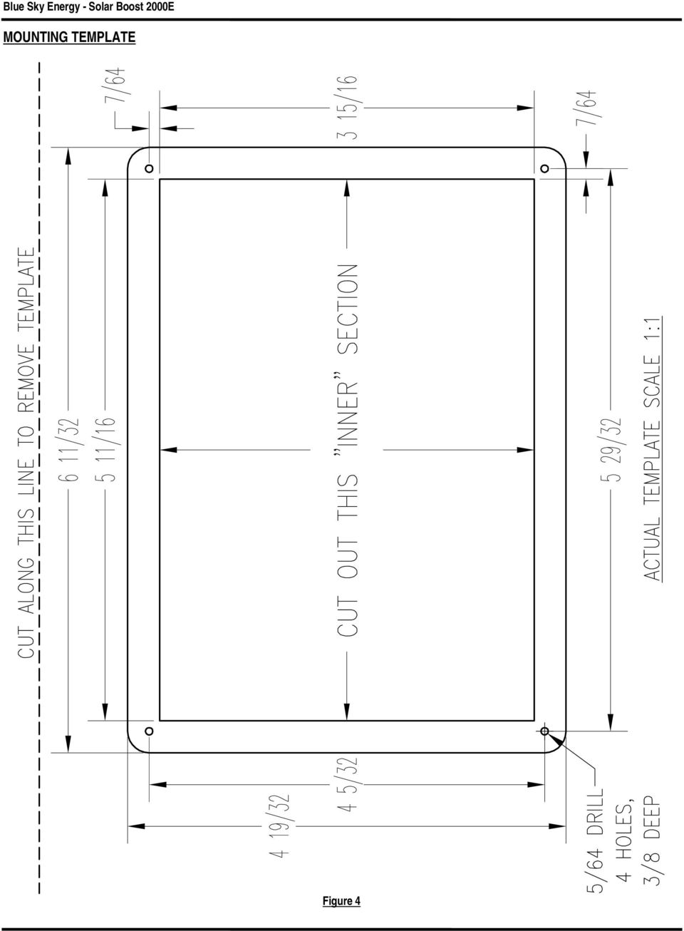
7 SELECTING PV MODULES Installation and Operation Manual Voltage, current and power produced by Photovoltaic (PV) modules fluctuate widely with operating conditions. As a result a set of test conditions referred to as Standard Test Conditions (STC) are used to rate modules in a meaningful manner and accurately predict real world performance. STC ratings are not maximum or optimal ratings. Conditions can be present where VOC and ISC approach 1.25 times STC ratings which is why National Electrical Code and our recommendations call for 1.25 derating of both VOC and ISC. Yet in real world conditions IMP is commonly only about 75 80% of IMP at STC. Key PV module specifications; PMAX Maximum power in watts (PMAX = VMP x IMP) VOC Voltage with module open circuit (typically 20 22V for 12V nominal modules) VMP Voltage where module produces Maximum Power (typically 17 18V for 12V nominal modules) IMP Current where module produces Maximum Power ISC Current with module Short Circuit The 2000E will provide the best MPPT current boost performance if all PV modules are identical. Dissimilar modules should have VMP values within 0.5V or better and be of the same basic cell technology so their VMP will tend to track as operating conditions change. If module types are very different consider using a separate charge controller for each module type to obtain the best MPPT current boost performance. Select PV modules that do not exceed the maximum ratings shown below, and preferably produce at least 3.5 amps of IMP per 100 amp-hours of battery capacity. For more detail on PV module sizing see technical bulletin # at Maximum PV STC TEMPERATURE COMPENSATION Maximum PV STC Maximum PV STC Recommended range of VMP at STC Nominal 12V PV 340W 20A 24.0V V For temperature compensation to operate, battery temperature sensor p/n must be installed and temperature compensation enabled via dip switches 3 & 4. The sensor is electrically isolated and may mount to any battery terminal, but battery negative is preferred. Select a temperature compensation characteristic that most closely matches the battery manufacturers recommendation. Most 12 volt flooded or GEL lead-acid chemistry batteries require the 30.0 millivolts/ C ( 5.00mV/ C/cell) setting. NiCd and many lead-acid chemistry AGM type batteries require the 20.0 millivolts/ C ( 3.33mV/ C/cell) setting. BATTERY AND PV WIRING WARNING: Do not attach a sensor or any connections other than Blue Sky Energy battery temperature sensor p/n to the temperature sensor terminals. Be certain to observe proper RED/BLK polarity as shown in Figure 3. The 2000E cannot properly limit and control battery voltage if temperature compensation is enabled with the sensor installed reverse polarity. Additionally, output current will be disabled if temperature compensation is enabled without the sensor installed. SWITCH SWITCH TEMPERATURE COMPENSATION 3 4 OFF OFF DISABLED ON ON 30.0 millivolts/ C Flooded Lead-Acid ( 5.00mV/ C/cell 6 cells) ON OFF 20.0 millivolts/ C NiCd ( 2.00mV/ C/cell 10 cells) AGM Lead-Acid ( 3.33mV/ C/cell 6 cells) The 2000E panel should be mounted in a dry location that provides easy routing of large size wires to the PV array and battery, and keeps PV/battery wire length as short as practical. The location should also provide free air circulation around the front of the panel, and if possible, around the rear. Take great care not to touch or damage circuit board components as this damage is not covered under the limited warranty. Figure 4 provides a 1:1 template for the panel cut-out. Wiring and connections used with the 2000E can have a significant effect on current boost performance. The 2000E increases charge current by transforming previously wasted or unharvested power into useable charge current. The effect wiring has on current boost performance is that power wasted heating wires or connections is power that becomes unavailable to charge the battery. A desirable installation will produce a total system wiring voltage drop of 3% or less. The lengths shown in Table 2 are one way from the PV modules to the battery with the 2000E located along the path. Wire length can be increased inversely proportional to actual current. If current was reduced by ½ (to 10 amps), wire lengths could be doubled and still provide the same 3% voltage drop. MAXIMUM CONDUCTOR PAIR LENGTH 3% VOLTAGE DROP WIRE GAUGE AWG 12 VOLT FEET / METERS 12 AWG 6.4 / AWG 10.2 / AWG 16.2 / AWG 25.7 / AWG 40.8 / 12.5 TABLE 2 6

8 SETUP AND WIRING DIAGRAM The 2000E cannot limit and control battery voltage if temperature compensation is enabled with sensor installed reverse polarity. Output charge current will be disabled if temperature compensation is enabled without sensor installed. SETTING CHARGE VOLTAGE FIGURE 3 Charge voltage should be set to the battery manufacturers recommendations. The factory setting of 14.0 volts is suitable for most lead-acid chemistry batteries and does not typically require adjustment. For a predominately float application a somewhat lower voltage of 13.8 volts may be beneficial in decreasing water loss. For a heavily cycling application, a somewhat higher voltage of 14.5V may be beneficial in decreasing charge time and increasing amp-hours delivered. The adjustment potentiometer location is shown in Figure 3. With the Charge Status LED blinking indicating that the battery at or near full charge, adjust the charge voltage potentiometer to the desired battery charge voltage as displayed on the 2000E digital display. If optional temperature compensation option is installed, disable temperature compensation, adjust the charge voltage to the desired 80 F value, and then turn temperature compensation back on. Since charge voltage is calibrated by adjusting actual battery charge voltage as displayed on the 2000E, setting charge voltage therefore requires that the battery be at or near full charge so that the unit is actually controlling battery voltage at the charge voltage setpoint. This can sometimes be hard to achieve when battery capacity is large compared to available PV charge current. Charge Voltage Calibration Tool P/N as described in technical bulletin # simplifies charge voltage calibration be eliminating the need to have the battery be highly charged. To access this and other technical bulletins, see MAXIMUM POWER VOLTAGE The nominal setting for this adjustment is the difference between the PV panel s open circuit voltage (VOC) and maximum power voltage (VMP). These voltage values are typically listed on both the PV panel datasheet and on the rating label affixed to each PV panel. This value needs to be set correctly for the MPPT system to deliver maximum current boost. The factory setting is 4.4 volts which is the appropriate value for many popular 36 cell PV modules. These modules typically list VOC at 21.4 volts and VMP at 17.0 volts, which yields; 21.4 volts volts = 4.4 volts. OPTIMIZING MPPT The combined effects of manufacturing tolerances in the PV panel and wiring resistance in a particular installation can sometimes shift the optimum setting. While not required, it is recommended that for maximum MPPT current boost performance this adjustment be fine-tuned following installation. This is a one-time setup and does not require seasonal adjustment. Fine tuning is also desirable following installation of additional PV panels or other substantial system change. Fine tuning is easily accomplished by slowly adjusting the MPPT adjust potentiometer to obtain maximum Output Charge Current. Adjustment is best done in near full sun with a discharged battery and cool ambient temperatures. The red MPPT Active LED above the potentiometer turns on when MPPT is 7

9 Installation and Operation Manual functioning and adjustment can be made. Verify that the LED remains on at the maximum current adjustment point, and as you check for a slight drop in current on either side of the maximum point. If LED does not remain on, MPPT is not operating due to a combination of high PV temperature and/or high battery voltage. MPPT can usually be made to operate by lowering battery voltage through application of a heavy DC load. If in doubt, leave the adjustment at the factory default position of midway between 11:00 and 12:00 o clock as shown in Figure 3. Note that the LED briefly turns off every 10 seconds while the system recalculates the MPPT operating point. TROUBLESHOOTING GUIDE SYMPTOM PROBABLE CAUSE ITEMS TO EXAMINE OR CORRECT Completely dead, no display No battery power Battery disconnected, overly discharged, or connected reverse polarity. Battery powers the system, not PV. Battery voltage must be present for unit to operate. Display OK, but PV disconnected Verify PV connection. Requires PV to supply at least 0.15A at 14V to begin charge. system will not turn on PV reverse polarity (charge status LED Reverse polarity PV will cause front panel to heat, and display to show negative PV current off) if battery is connected. PV- connected to BAT- PV- & BAT- must be separate for proper operation. PV- must receive earth ground via shunts in the 2000E which internally connect PV- to BAT-. External connection prevents proper operation of the internal current measurement system. Charge status LED on in Bulk, but no output charge current Dip switches set incorrectly Low PV power Double check dip switches #1-4. Correct PV s. Charge status LED on & blinking in Constant Voltage mode but no output charge current Charge status LED on in Constant Voltage, relays click on/off Relays click on/off rapidly Charge status LED blinking, charge voltage high Charge current is lower than expected, PV current may be low as well MPPT Current boost is less than expected Battery voltage greater than charge voltage setpoint Temp comp. enabled without sensor, or sensor failed open Battery voltage too low Charge current is very low and the system is on the edge of being able to stay on PV- connected to BAT- Dip switch #2 off System in equalize mode Temp sensor failed short, or installed reverse polarity Battery is highly charged Worn out PV modules Low insolation PV- connected to BAT- MPPT improperly setup PV maximum power voltage (VMP) is not much higher than battery voltage, leaving little extra power to be extracted This is normal operation. Output is off due to high battery voltage which may be caused by other charging systems. Disable temp compensation, or replace sensor. Proper temp sensor terminal voltage when connected is 2.98V at 25 C, changing at +10mV/ C. A minimum battery voltage of 9.0V is required for the unit to operate. If charge current is very low ( A) because battery voltage is at setpoint, relays may switch on/off. This normal and will cause no harm. The on/off symptom will go away with a slight increase or decrease in battery voltage, or load current. PV- & BAT- must not connect together external to controller for proper operation. Double check dip switch #2, must always be on. Used for factory test only. Disable equalize by pressing the equalize pushbutton. Replace sensor, or remove sensor and disable temp compensation. Proper temp sensor terminal voltage when connected is 2.98V at 25 C, changing at +10mV/ C. Normal operation, system will be in Constant Voltage mode and current is reduced to control battery voltage. Replace, or use as is. Atmospheric haze, PV s dirty, sun low on horizon, etc. PV- & BAT- must be separate for proper operation. PV- must receive earth ground via shunts inside the 2000E which internally connect PV- to BAT-. External connection prevents proper operation of the internal current measurement system. See Maximum Power Voltage and Optimizing MPPT sections. May result from PV s with low VMP. PV s with higher VMP produce greater power and current boost potential. PV s with VMP 17V work best, PV s with <36 cells tend to work poorly. Excessive PV wiring voltage drop due to undersize wiring, poor connections, etc., consumes and wastes available power. This simulates having PV s with low VMP. Battery is nearly charged and battery voltage is near setpoint. Output during MPPT operation is constant power so higher battery voltage produces less charge current. At high temperature, unit shuts down PV s hot MPPT improperly setup System temporarily shuts down due to high temperature VMP and available power decrease with increasing PV cell temperature. Cooler PV s will produce greater boost. MPPT LED off indicates that extra power is not available from PV array. It is normal for boost to decrease as temperature rises. See Maximum Power Voltage and Optimizing MPPT sections. Improve ventilation or reduce PV power. Providing sufficient ventilation or operating conditions which do not cause over temperature shut down will improve reliability. 8

10 SPECIFICATIONS Output current rating... 25A System voltage... 12V nominal Max. PV Open circuit voltage... 30V Max. battery voltage... 30V Output current limit... 25±1A Volt meter full scale range V Volt meter accuracy... ±0.1% full-scale Current meter full scale range... ±26A Current meter accuracy... ±0.75% full-scale Charge voltage adjustment V typical Equalization voltage... charge set +1.2V Power conversion efficiency... 95% 15A Temperature compensation coefficient Lead-acid mV/ C NiCd mV/ C Current consumption Standby... 17mA typical Charge on... 90mA typical Panel dimensions Hx6.4 Wx1.8 D Storage temperature range to +85 C Specified temperature range... 0 to +40 C Extended range to +50 C (will operate but may not meet specifications, see Technical Bulletin #100206) As a part of our continuous improvement process specifications are subject to change without prior notice. FIVE YEAR LIMITED WARRANTY Blue Sky Energy, Inc. (hereinafter BSE), hereby warrants to the original consumer purchaser, that the product or any part thereof shall be free from defects due to defective workmanship or materials for a period of five (5) years subject to the conditions set forth below. 1. This limited warranty is extended to the original consumer purchaser of the product, and is not extended to any other party. 2. The limited warranty period commences on the date the product is sold to the original consumer purchaser. A copy of the original purchase receipt identifying purchaser and date of purchase, must accompany the product to obtain warranty repairs. 3. This limited warranty does not apply to, and future warranty shall become void, for any product or part thereof damaged by; a) alteration, disassembly or application of a foreign substance, b) repair or service not rendered by a BSE authorized repair facility, c) accident or abuse, d) corrosion, e) lightning or other act of God, f) operation or installation contrary to instructions pertaining to the product, or g) cosmetic aging. 4. If BSE s examination of the product determines that the product is not defective the consumer shall be charged a test and evaluation fee of $20 and be responsible for all transportation costs and insurance related to returning the product to the consumer. The consumer is ultimately responsible for proper installation and operation of the product and BSE s prior troubleshooting assistance shall not serve as a waiver of the test and evaluation fee. The test and evaluation fee is subject to change without prior notice. 5. If within the coverage of this limited warranty, BSE shall repair or replace the product at BSE s sole discretion and return the product via standard ground transportation of BSE s choosing within the continental US. The consumer shall be responsible for all transportation costs and insurance to return the product outside the continental US, and for all transportation costs and insurance related to expedited return of the product. BSE s liability for any defective product or any part thereof shall be limited to the repair or replacement of the product. BSE shall not be liable for any loss or damage to person or property, or any other damages, whether incidental, consequential or otherwise, caused by any defect in the product or any part thereof. 6. Any implied warranty for merchantability or fitness for a particular purpose is limited in duration to the length of this warranty. 7. To obtain warranty repairs, contact BSE at to obtain a Returned Goods Authorization (RGA) number. Mark the outside of the package with the RGA number and return the product, postage prepaid and insured to the address below. The consumer is responsible for all transportation costs and insurance related to returning the product to BSE, and for any shipping damage which may void the warranty or increase the cost of repairs. Blue Sky Energy, Inc Fortune Way, Suite K Vista, CA USA Fax

11 MOUNTING TEMPLATE Figure 4
12 Volt 30 Amp Digital Solar Charge Controller
 12 Volt 30 Amp Digital Solar Charge Controller User s Manual WARNING Read carefully and understand all INSTRUCTIONS before operating. Failure to follow the safety rules and other basic safety precautions
AUTOMATIC BEST BATTERY SELECTOR INSTALLATION & OPERATION BBS-1600 BBS-1600E
 AUTOMATIC BEST BATTERY SELECTOR INSTALLATION & OPERATION BBS-1600 BBS-1600E SENS part no: 101314 Document revision: F DCN No. 106811 Date 8/3/15 1840 Industrial Circle Longmont, CO 80501 Fax: (303) 678-7504
CHARGING SYSTEMS INTERNATIONAL
 CHARGING SYSTEMS INTERNATIONAL INSTALLATION AND OPERATING INSTRUCTIONS FOR THE FOLLOWING BATTERY CHARGING SYSTEMS: MODELS MAX AMPS/BANK NO. OF BANKS BATTERY SYSTEM PRO XL 6 1 12 DUAL PRO XL 6 2 12/24 PRO
Amps Per Bank. Total Output. Battery System. Model Name. 6 amps 12 amps 10 amps 20 amps 30 amps 40 amps 15 amps 30 amps 45 amps
 Model Name Total Output Amps Per Bank Battery System Pro XL Dual Pro XL Pro SE Dual Pro SE Three Bank Pro SE Four Bank Pro SE Pro Charger Dual Pro Charger Three Bank Pro Charger 6 amps 12 amps 10 amps
12 Volt 30 Amp Digital Solar Charge Controller Installation & Operation Manual
 12 Volt 30 Amp Digital Solar Charge Controller Installation & Operation Manual This 30Amp charge controller is designed to protect your 12Volt Lead-acid or Gel-cell battery from being overcharge by solar
Solar Wind Microhydro Water Pumping Inverters Batteries Professional system design and installation
 Solar Wind Microhydro Water Pumping Inverters Batteries Professional system design and installation BATTERY CHARGING GUIDELINES FOR GLOBAL/DAVIDSON TUBULAR PLATE BATTERIES Introduction Your Global/Davidson
Installation and Operating Instructions (for chargers shown below)
") Installation and Operating Instructions (for chargers shown below) For additional information please call our Technical Support Group 800.742.2740 PRO CHARGING SYSTEMS, LLC 1551 Heil Quaker Boulevard,
Installation and Operating Instructions (for chargers shown below) For additional information please call our Technical Support Group 800.742.2740 PRO CHARGING SYSTEMS, LLC 1551 Heil Quaker Boulevard,
Manual. Solar Fountain Mobile Phone Charger
 EN Manual Solar Fountain Mobile Phone Charger Copyrights 2008 Victron Energy B.V. All Rights Reserved This publication or parts thereof may not be reproduced in any form, by any method, for any purpose.
OWNER S MANUAL. Model AE150/AE300/AE500 1.5AMP MULTI-USE SMART BATTERY CHARGER READ ENTIRE MANUAL BEFORE USING THIS PRODUCT
 Model AE150/AE300/AE500 MULTI-USE SMART BATTERY CHARGER Certified by Californiia BCS Regulations AE300E AE500E 5AMP MULTI-USE AUTOMOTIVE BATTERY CHARGER 3AMP MULTI-USE SMART BATTERY CHARGER AE500E 5AMP
POWER TO GET THE JOB DONE
 52720 1.5 AMP SLOW 12 VOLT BATTERY CHARGER OWNER S MANUAL KEEPS BATTERIES FULLY CHARGED IN STORAGE Automatic over-charging protection Short circuit protection Reverse hook-up protection Overheat protection
EPSOLAR LS0512R / LS0524R. Solar Light Controller INSTRUCTION MANUAL. Please read this manual carefully before using the product!
 EPSOLAR LS0512R / LS0524R Solar Light Controller INSTRUCTION MANUAL Please read this manual carefully before using the product! LandStar LS0512R / LS0524R Solar Light Controller Nominal system voltage
BATTERY CHARGING GUIDELINES FOR 6-VOLT DEEP CYCLE BATTERIES
 BATTERY CHARGING GUIDELINES FOR 6-VOLT DEEP CYCLE BATTERIES Introduction Your 6-volt deep cycle battery set has been specially formulated for long cycle life and has particular voltage and specific gravity
Digital echo-charge. Owner s Manual. Xantrex Digital echo-charge Battery Charger
 Digital echo-charge Owner s Manual Xantrex Digital echo-charge Battery Charger Thank you for purchasing a Xantrex Digital echo-charge. Xantrex Technology Inc. takes pride in manufacturing quality products
Solar charger controller User s Manual
 Solar charger controller User s Manual Contents Important safety instructions... 6 1. Product description... 8 1.1 General description... 8 1.2 Features... 8 1.3 Maximum setpoint voltage limit... 8 1.4
6 & 12 Volt Battery and Systems Tester with 100 Amp Load
 6 & 12 Volt Battery and Systems Tester with 100 Amp Load Form No. 841-731 -000 DESCRIPTION This Load Tester tests 6 or 12 volt automotive-size lead-acid batteries under load. It will also test 6 or 12
LESTRONIC DV AUTOMATIC 12 OR 24 VOLT DUAL OUTPUT DUAL MODE BATTERY CHARGER MODEL 16350 TYPE 12/24EL40-10ET
 LESTRONIC DV AUTOMATIC 12 OR 2 VOLT DUAL OUTPUT DUAL MODE BATTERY CHARGER MODEL 16350 TYPE 12/2EL0-10ET PLEASE SAVE THESE IMPORTANT SAFETY AND OPERATING INSTRUCTIONS For correct operation of the equipment,
Solar Controller / Battery Charger User s Manual
 Solar Controller / Battery Charger User s Manual 1 Congratulations! You have made an excellent choice by purchasing this high quality KORR PWM solar controller which has been manufactured to the highest
Installation and Operating Instructions (for chargers shown below)
") Installation and Operating Instructions (for chargers shown below) For additional information please call our Technical Support Group 800.742.2740 PRO CHARGING SYSTEMS, LLC 1551 Heil Quaker Boulevard,
Installation and Operating Instructions (for chargers shown below) For additional information please call our Technical Support Group 800.742.2740 PRO CHARGING SYSTEMS, LLC 1551 Heil Quaker Boulevard,
LS1024B / LS2024B/ LS3024B. Solar Charge Controller USER MANUAL
 EPSOLAR LS1024B / LS2024B/ LS3024B Solar Charge Controller USER MANUAL Thank you very much for selecting our product! This manual offers important information and suggestions with respect to installation,
BATTERY CHARGER OWNER S MANUAL
 SAVE THESE INSTRUCTIONS This manual contains important safety and operating instructions for the automatic battery charger. Do not expose charger to rain or snow. Do not use and an attachment not recommended
PHOTOVOLTAIC SYSTEM CONTROLLERS SUNSAVER MODELS INCLUDED IN THIS MANUAL SS-6 / SS-6L SS-10 / SS-10L SS-10-24V / SS-10L-24V SS-20L SS-20L-24V
 PHOTOVOLTAIC SYSTEM CONTROLLERS OPERATOR S MANUAL SUNSAVER MODELS INCLUDED IN THIS MANUAL SS-6 / SS-6L SS-10 / SS-10L SS-10-24V / SS-10L-24V SS-20L SS-20L-24V 6A / 12V 10A / 12V 10A / 24V 20A / 12V 20A
Troubleshooting Guide, Freedom and Fleet Power Inverter/Chargers
 Technical Note Freedom/Fleet Power 512-0084-01-01 Rev 1 Troubleshooting Guide, Freedom and Fleet Power Inverter/Chargers Overview This document is a guide for troubleshooting inverters, battery chargers,
VLT Series 300 Watt True Sine Wave Inverter
 VLT Series 300 Watt True Sine Wave Inverter PURE SINE WAVE INVERTER I ON 0 OFF REMOTE CONTROL AC OUTPUT POWER STATUS Vout Vin Models VLT12-300 VLT24-300 300 Watt VLT Series Inverter - 1 - TABLE OF CONTENTS
BC-5000 OPERATIONS MANUAL BATTERY CAPACITY TESTER COFKO LLC.
 BC-5000 BATTERY CAPACITY TESTER OPERATIONS MANUAL COFKO LLC. COPYRIGHT 2010 1 UNPACKING As you unpack your new BC-5000 battery capacity tester, inspect the tester for signs of shipping damage. If shipping
Advantium 2 Plus Alarm
 ADI 9510-B Advantium 2 Plus Alarm INSTALLATION AND OPERATING INSTRUCTIONS Carefully Read These Instructions Before Operating Carefully Read These Controls Corporation of America 1501 Harpers Road Virginia
Tracer-1206RN / 1210RN / 1215RN. Maximum Power Point Tracking Solar Charge Controller INSTRUCTION MANUAL
 Tracer-1206RN / 1210RN / 1215RN Maximum Power Point Tracking Solar Charge Controller INSTRUCTION MANUAL Thank you very much for selecting our product! This manual offers important information and suggestions
Battery Power Inverters
 Battery Power Inverters Renogy 500W 1000W 2000W Pure Sine Wave Inverter Manual 2775 E. Philadelphia St., Ontario, CA 91761 1-800-330-8678 1 Version 1.1 Important Safety Instructions Please save these instructions.
User s Manual Before using the inverter, you need to read and save the safety instructions.
 User s Manual Before using the inverter, you need to read and save the safety instructions. STI SERIES (STI200, STI300, STI500, STI700, STI1000) Power Frequency Pure Sine Wave Inverter The information
Automatic taper of charge rate for superior battery life through good equalization of cells and low water use rate.
 *00151* FEATURES Automatic taper of charge rate for superior battery life through good equalization of cells and low water use rate. Silicon diodes with inherent surge protection operated at a conservative
MANUAL D250S DUAL. Solar panel + Vehicle ground/solar panel
 MANUAL CONGRATULATIONS on the purchase of your new CTEK professional battery management unit. This unit is part of a range of professional battery chargers from CTEK SWEDEN AB. It represents the latest
INSTRUCTION MANUAL EPSOLAR. Tracer-2210RN / 2215RN. Maximum Power Point Tracking Solar Charge Controller
 EPSOLAR Utility model patent NO. 201120064092.1 Tracer-2210RN / 2215RN Maximum Power Point Tracking Solar Charge Controller INSTRUCTION MANUAL Thank you very much for selecting our product! This manual
MANUAL. * Supply plugs may differ to suit your wall socket. EN 3. Continue to press the MODE-button to combine charging program with charging options.
 MX MANUAL CONGRATULATIONS to the purchase of your new professional switch mode battery charger. This charger is included in a series of professional chargers from CTEK SWEDEN AB and represents the latest
SOLAR POWER - THE NEW WAY TO RV!
 IMPORTANT! - YOU'RE SOLAR READY SOLAR POWER - THE NEW WAY TO RV! Your RV is PRE-WIRED for SOLAR POWER! Benefits of Solar Zamp Solar Portable Solar Kit Maximize Battery Life Electrical Independence Green,
MULTI XS 3600. Battery charger. For lead-acid batteries 1,2-120Ah
 MULTI XS 3600 Battery charger For lead-acid batteries 1,2-120Ah User s Manual and a guide to professional battery charging For Starter/Deep Cycle batteries EN INTRODUCTION Congratulations on your purchase
Charge Regulator SCR 12 Marine
 Charge Regulator SCR 12 Marine Manual Many thanks for purchasing a superwind product. The SCR 12 Marine is a charge regulator of highest quality and will perfectly and reliably charge your batteries for
3 WATT LED SPOTLIGHT Model No. SLM - 3801
 3 WATT LED SPOTLIGHT Model No. SLM - 3801 OWNER'S MANUAL Customer Service Tel: 1-800-268-3319 Superex Canada Ltd, Toronto,M2H 3B8 Made in China Table of Contents A). Important Safety Instructions B). Charging
Dear Neuton Owner, This is a helpful hint to guide you in getting the most out of your NEUTON Battery and Charger.
 Battery-Powered Mower NEUTON 24-Volt Charger Instructions Booklet Dear Neuton Owner, In order for you to get the most out of your Neuton Mower, we recently reviewed and revised our battery-charging instructions.
CHAPTER 5 PHOTOVOLTAIC SYSTEM DESIGN
 CHAPTER 5 PHOTOVOLTAIC SYSTEM DESIGN 5.1 Introduction So far in the development of this research, the focus has been to estimate the available insolation at a particular location on the earth s surface
3000W Power Inverter
 3000W Power Inverter OWNER S MANUAL Model number-4573000 TO REDUCE THE RISK OF INJURY, USER MUST READ AND UNDERSTAND THIS INSTRUCTIONAL MANUAL. THIS MANUAL CONTAINS IMPORTANT INFORMATION REGARDING THE
INSTALLER S & OWNER S MANUAL
 INSTALLER S & OWNER S MANUAL HVAC INSTALLER: PLEASE LEAVE MANUAL FOR HOMEOWNER DEH 3000 DEH 3000 Part No. 4028539 Dehumidifier & Ventilation System Controller P.O. Box 8680 Madison, WI 53708 TOLL-FREE
BATTERY CHARGER MULTI US 7000
 US Switch Mode BATTERY CHARGER For lead-acid batteries 14-150 Ah MULTI US 7000 User s Manual and a guide to professional battery charging For Starter/Deep Cycle batteries INTRODUCTION The MULTI US 7000
Instructions & Safety Information Models A220-20D and A220-20L Version 2
 Quick 220 Voltage Converting Power Supply Instructions & Safety Information Models A220-20D and A220-20L Version 2 Quick 220 Systems LLC PO Box 47489 Phoenix, Arizona 85068-7489 800-347-0394 602-938-6057
Temperature Compensated Charging of Lead Acid Batteries
 Technical Note Batteries 512-0101-01-01 Rev 1 Temperature Compensated Charging of Lead Acid Batteries Introduction To ensure optimum charging of lead acid batteries, the charge voltages should be adjusted
AGS. Owner's Manual. Xantrex Automatic Generator Start Control System
 AGS Owner's Manual Xantrex Automatic Generator Start Control System TABLE OF CONTENTS INTRODUCTION...3 Main Features...3 Safety Summary...3 THINGS YOU SHOULD KNOW...4 THEORY OF OPERATION...5 System...5
www.ringautomotive.co.uk Instructions: Retain these instructions for future reference SmartChargePro35 RSCPR35-12v, 2 / 8 / 16 / 35A
 SmartChargePro7 RSCPR7-12v, 7A SmartChargePro10 RSCPR10-12v, 10A SmartChargePro15 RSCPR15-12v, 15A SmartChargePro25 RSCPR25-12v, 2 / 6 / 12 / 25A SmartChargePro35 RSCPR35-12v, 2 / 8 / 16 / 35A SmartChargePro50
If you accidentally get battery acid on your skin, flush it with lots of water
 RV Battery Savvy To properly maintain and extend the life of your RV batteries you need to have a basic understanding of what a battery is and how it works. Batteries used in RVs are lead acid batteries.
MANUAL EN 3. Continue to press the MODE-button to combine charging program with charging options.
 MANUAL CONGRATULATIONS on the purchase of your new professional switch mode battery charger and tester. This charger and tester is included in a series of professional chargers from CTEK Sweden AB and
MANUAL CONGRATULATIONS IMPORTANT SAFETY INSTRUCTIONS
 MANUAL CONGRATULATIONS on the purchase of your new CTEK professional battery management unit. This unit is part of a range of professional battery chargers from CTEK SWEDEN AB. It represents the latest
User Manual HomeGrid 3000 Solar Generator
 User Manual HomeGrid 3000 Solar Generator For more information and instruction videos visit: www.pointzeroenergy.com/learn/videos/ HomeGrid 3000 Solar Generator Congratulations on purchasing Point Zero
SOLAR ELECTRIC MODULE ES-124 & ES-62T Owners Manual and Installation Guide
 SOLAR ELECTRIC MODULE ES-124 & ES-62T Owners Manual and Installation Guide circuit. Reverse connection will damage the module and may result in fire. CAUTIONS Solar electric modules produce DC electricity
Installation and Operation Guide for PD4100 Series Power Control Centers
 Installation and Operation Guide for PD4100 Series Power Control Centers Extended warranties are available for purchase at www.progressivedyn.com Member Thank you for selecting Progressive Dynamics as
Mini Power Bank and Charger
 Mini Power Bank and Charger Owner s Manual Please read before using this equipment. Your charger is ETL listed to UL standards and meets all applicable FCC standards. WARNING: To reduce the risk of fire
MXS 3. MANUAL FULLY CHARGED PULSE, MAINTENANCE CHARGING EN 3 SUPPLY PLUG* MAINS CABLE CTEK COMFORT CONNECT CHARGE CABLE ERROR LAMP MODE- BUTTON
 MODE 12V/ MXS 3. MANUAL CONGRATULATIONS to the purchase of your new professional switch mode battery charger. This charger is included in a series of professional chargers from CTEK SWED AB and represents
GV-Boost Manual. 8A Input / 105-350W IMPORTANT SAFETY INSTRUCTIONS SAVE THESE INSTRUCTIONS. Solar Charge Controllers with Maximum Power Point Tracking
 GV-Boost Manual Solar Charge Controllers with Maximum Power Point Tracking For models: GVB-8-Pb-12V: GVB-8-Pb-24V: GVB-8-Pb-36V: GVB-8-Pb-48V: GVB-8-Li-**.*V: 12V Lead-Acid/AGM/Gel/Sealed/Flooded 24V Lead-Acid/AGM/Gel/Sealed/Flooded
BATTERY CHARGER OPERATOR'S MANUAL
 ASSOCIATED BATTERY CHARGER OPERATOR'S MANUAL IMPORTANT SAFETY INSTRUCTIONS 1. SAVE THESE INSTRUCTIONS. This manual contains important safety and operating instructions for models 9006, 9010, 9014, 9050,
Battery Charger For Nickel Cadmium and Nickel-Metal Hydride Rechargeable Batteries Model PSN Series
 Battery Charger For Nickel Cadmium and Nickel-Metal Hydride Rechargeable Batteries Model PSN Series Operating Instructions WARNING CONCERNING THE REMOVAL OF COVER: CAUTION: TO PREVENT THE RISK OF ELECTRIC
POOL SUNSHINE IONIZER MODELS SPD, SPD2 AND SPS INSTALLATION INSTRUCTIONS
 Sunshine Pool Products, LLC Manufacturer of Quality Pool & Spa Products 902 W 2010 S, Syracuse, Utah 84075 USA Voice: 801-825-4523 Website: www.sunshinepool.com Email: info@sunshinepool.com POOL SUNSHINE
TROUBLESHOOTING GUIDE
 TROUBLESHOOTING GUIDE LESTRONIC II BATTERY CHARGER FOR MOTIVE POWER BATTERIES PLEASE SAVE THESE IMPORTANT SAFETY AND OPERATING INSTRUCTIONS For correct operation of the equipment, it is important to read
THIS MANUAL REFERS TO THE FOLLOWING MODULES G1501210 G3001220 G3002410 G6002420 EG1501210 EG3001220 EG3002410 EG6002420
 Guardian series UL/CSA Approved Automatic Battery Chargers INSTALLATION AND OPERATION THIS MANUAL REFERS TO THE FOLLOWING MODULES G1501210 G3001220 G3002410 G6002420 EG1501210 EG3001220 EG3002410 EG6002420
543-0032-00, 943-0032-00. User s Manual
 543-0032-00, 943-0032-00 User s Manual 1 Comfort Alert Diagnostics Faster Service And Improved Accuracy The Comfort Alert diagnostics module is a breakthrough innovation for troubleshooting heat pump and
400 Amp Rechargeable Jump Start System RAC-HP082
 400 Amp Rechargeable Jump Start System RAC-HP082 MAINTENANCE Always inspect the tool before use to ensure the cables are in good condition and the clamps are clean and free from corrosion. Keep clean by
EN 3 ABSORPTION, READY TO USE ANALYSE BULK DESULPHATION SOFT START. L: 2000 mm MODE- BUTTON SUPPLY PLUG* SUPPLY
 MODE 24V/ MANUAL MXT 14 CONGRATULATIONS to the purchase of your new professional switch mode battery charger. This charger is included in a series of professional chargers from CTEK SWEDEN AB and represents
1. Connect the charger to the battery. 2. Connect the charger to the wall socket. 3. Press the MODE-button to select charging program.
 MANUAL CONGRATULATIONS to the purchase of your new professional switch mode battery charger. This charger is included in a series of professional chargers from CTEK SWEDEN AB and represents the latest
2/8/12 AMP Smart Charger OWNER S MANUAL
 2/8/12 AMP Smart Charger OWNER S MANUAL Model number-457808 Important For safe and optimum performance, charger must be used properly. Carefully read and follow all instructions and guidelines in this
ACCUSENSE CHARGE SERIES ON/OFF BOARD FULLY AUTOMATIC BATTERY CHARGER
 Diversified Power International 414 Century Court Piney Flats, TN 37686 (423) 538-9002 (423) 538-9202 (fax) www.dpipower.com ACCUSENSE CHARGE SERIES ON/OFF BOARD FULLY AUTOMATIC BATTERY CHARGER SPECIFICATIONS:
12V Battery Charger & Engine Starter
 OPERATOR S MANUAL 12V Battery Charger & Engine Starter Model No. 28 71222 Read and follow all Safety Rules and Operating Instructions before Every Use of this Product. SAVE THESE INSTRUCTIONS. Sears Brands
White Paper SolarEdge Three Phase Inverter System Design and the National Electrical Code. June 2015 Revision 1.5
 White Paper SolarEdge Three Phase Inverter System Design and the National Electrical Code June 2015 Revision 1.5 Shalhevet Bar-Asher; SolarEdge Technologies, Inc. Bill Brooks, PE; Brooks Engineering LLC
GEN Series. On-Board Battery Chargers. Owner s Manual & User Guide
 On-Board Battery Chargers Owner s Manual & User Guide WARNING Risk of SERIOUS INJURY OR DEATH. ELECTRICAL SHOCK, EXPLOSION, FIRE, AND EYE INJURY HAZARDS. PROTECT YOURSELF AND OTHERS. Before use, READ AND
Periodic Verification System Model 775PVS
 Periodic Verification System Model 775PVS Instruction Manual Contents 1 Description... 1 775PVS System... 1 Model 775 Fieldmeter... 2 Model 775C Charger... 2 Model 775P Plate Assembly... 3 2 Operation...
Installation Instructions for Solar Pumps USER MANUAL FOR SPS, SPC, SPSC SPQB, SPGJ SERIES SOLAR PUMPS AND PUMP CONTROLLERS
 Installation Instructions for Solar Pumps USER MANUAL FOR SPS, SPC, SPSC SPQB, SPGJ SERIES SOLAR PUMPS AND PUMP CONTROLLERS PO Box 80, Tuakau 2342 ph 0800 14 48 65 e-mail: hunkin-garden@xnet.co.nz www.hunkin.co.nz
ST Series POWER SUPPLIES USER INSTRUCTIONS
 Introduction These instructions detail the installation and operation requirements for the ST20 & ST35 power supplies. These have been designed for operation in RV s providing a DC power system, with optional
PSC-A5 Solar Charge Controller Manual
 ( 5A, 12V/24V Output, Double Mode ) 1. Introduction: This controller is suitable for 12V and 24V solar photovoltaic system. The charge and discharge current is 5A. The maximum solar panel for 12V system
AUTO CHARGE 3 STEP AUTOMATIC BATTERY CHARGER
 FILE: IM_091-120-12E-20 Rev A., 05-06-08 INSTRUCTION MANUAL AUTO CHARGE 3 STEP AUTOMATIC BATTERY CHARGER R MODEL #091-120-12E-20 for ODYSSEY AGM BATTERIES CAUTION This charger is calibrated to the ODYSSEY
Mobile Data Power Model: MDP-25
 Mobile Data Power Model: MDP-25 Topic Section Features... 2 Operational Features Summary... 2 Back-up Battery Power Internal Charger Voltage Spike Protection RF Noise Filtering Warning of Imminent Loss
Model SRMD Setra Remote Monitoring Display
 Model SRMD Setra Remote Monitoring Display 1.0 GENERAL INFORMATION Thank you for purchasing the Setra Remote Monitoring Display (SRMD). The SRMD is a digital panel meter with a bright 1 LED display for
CONTROL PANEL INSTALLATION INSTRUCTIONS. Single Phase Simplex Page 2-7. 3-Phase Simplex Page 8-13
 CONTROL PANEL INSTALLATION INSTRUCTIONS Single Phase Simplex Page 2-7 3-Phase Simplex Page 8-13 Single Phase Simplex SXL21=3, SXL24=3, SXH21=3, and SXH24=3 Manufactured by SJE-Rhombus Installation Instructions
Installation and Operation Guide for PD4000 Series Power Control Center
 Extended warranties are available for purchase at www.progressivedyn.com Installation and Operation Guide for PD4000 Series Power Control Center Member Thank you for selecting Progressive Dynamics as your
Single Station Remote Alarm
 ADI 5106G Certified ISO 9001:2000 Single Station Remote Alarm 529 5106-01-120 529 5106-01-220 INSTALLATION AND OPERATING INSTRUCTIONS Carefully Read These Instructions Before Operating Controls Corporation
Model HPX10 Series Automatic Battery Charger User s Manual Rev. 1.0 October 17, 2006
 B R A N D Model HPX10 Series Automatic Battery Charger User s Manual Rev. 1.0 October 17, 2006 For Sales, Support and Service phone: 407-331-4793 fax: 407-331-4708 website: www.xenotronix.com email: information@xenotronix.com
Seven function digital multimeter
 Seven function digital multimeter 98025 Set up And Operating Instructions Distributed exclusively by Harbor Freight Tools. 3491 Mission Oaks Blvd., Camarillo, CA 93011 Visit our website at: http://www.harborfreight.com
NASS Solar DC Pool Pumps
 Technical Data Manual For NASS Models: NASS 500 NASS 900 NASS 1200 NASS 2200 X NASS 2200 JP15-14/600 JP31-19/1000 JP35-22/2000 JP60-13/2200 NASS Solar DC Pool Pumps NASS JP Type DC Pool Pumps For pumping,
Owner s Manual. ULTRA-POWER II ACCU-POWER & ACCU-POWER ONBOARD Solid State Fully Automatic Chargers. Manual Number 1017361. Edition Code 0493B0101A
 Owner s Manual ULTRA-POWER II ACCU-POWER & ACCU-POWER ONBOARD Solid State Fully Automatic Chargers Manual Number 1017361 Edition Code 0493B0101A General Information This instruction manual should be read
OWNER S MANUAL 2.5/3.0 ACS PANEL (ADVANCED CONTROL SYSTEM) 7725 Lougheed Highway Burnaby, BC V5A 4V8 Canada
 7725 Lougheed Highway Burnaby, BC V5A 4V8 Canada") 2.5/3.0 ACS PANEL (ADVANCED CONTROL SYSTEM) OWNER S MANUAL 7725 Lougheed Highway Burnaby, BC V5A 4V8 Canada Tel: (604) 420-1585 Fax: (604) 420-1591 http:// www. statpower.com PROsine 2.5/3.0 ACS Panel
2.5/3.0 ACS PANEL (ADVANCED CONTROL SYSTEM) OWNER S MANUAL 7725 Lougheed Highway Burnaby, BC V5A 4V8 Canada Tel: (604) 420-1585 Fax: (604) 420-1591 http:// www. statpower.com PROsine 2.5/3.0 ACS Panel
MANUAL EN 3 SUPPLY PLUG* MAINS CABLE CTEK COMFORT CONNECT ABSORPTION, READY TO USE ANALYSE FLOAT, FULLY CHARGED PULSE, MAINTENANCE CHARGING
 MODE 12V/ MANUAL CONGRATULATIONS to the purchase of your new professional switch mode battery charger. This charger is included in a series of professional chargers from CTEK SWEDEN AB and represents the
ITC-BTTN Cellular Bluetooth Gateway. Owner s Manual 1
 ITC-BTTN Cellular Bluetooth Gateway Owner s Manual 1 2 Table of Contents Introduction...3 Package Contents...3 XLink Connections Diagram...4 Setup...5 Pairing your Bluetooth Cell Phone to the XLink...6
Hygro-Thermometer + InfraRed Thermometer Model RH101
 User's Guide Hygro-Thermometer + InfraRed Thermometer Model RH101 Introduction Congratulations on your purchase of the Extech Hygro-Thermometer plus InfraRed Thermometer. This device measures relative
OUTPUT CABLE CONNECTIONS:
 Tender Plus: Models: 12V1.25A and 6V1.25A The Tender Plus 12 Volt, 1.25 Amp 6 Volt, 1.25 Amp GENERAL DESCRIPTION: The Tender Plus battery charger is a desktop, portable, linear power converter that has
Ultrasonic Jewelry/DVD Cleaner. make jewelry, dvds and more sparkle like new
 Ultrasonic Jewelry/DVD Cleaner make jewelry, dvds and more sparkle like new Table of contents Cautions & Warnings...................................................... 2-4 Location of Controls........................................................
Li Battery Pack & Charger Safety & Operating Instructions
 Li Battery Pack & Charger Safety & Operating Instructions NEUTON Power Equipment 75 Meigs Road Vergennes, VT 05491 Toll-Free phone: 1-866-NEUTON1 (638-8661) Fax: 1-802-877-1213 Website: www.neutonpower.com
Installation/Operator Manual For use with WFCO ULTRA III Power Center Model WF-8712P and WF-8725P
 Installation/Operator Manual For use with WFCO ULTRA III Power Center Model WF-8712P and WF-8725P Distributed in the U.S.A. and Canada by CHENG USA, INC. Sales (574) 294-8997 Warranty Service (877) 294-8997
Constant Voltage Charger Selection for VRLA Batteries
 TECHNICAL BULLETIN 41-2129 Constant Voltage Charger Selection for VRLA Batteries Please Note: The information in this technical bulletin was developed for C&D Dynasty 12 Volt VRLA products. While much
SDX Submersible Depth Transmitter User Manual
 SDX Submersible Depth Transmitter User Manual January 2011 USER INFORMATION Stevens makes no warranty as to the information furnished in these instructions and the reader assumes all risk in the use thereof.
PART 1 - INTRODUCTION...
 Table of Contents PART 1 - INTRODUCTION... 3 1.1 General... 3 1.2 Sensor Features... 3 1.3 Sensor Specifications (CDE-45P)... 4 Figure 1-1 CDE-45P Sensor Dimensions (standard, convertible style)... 4 PART
TELEDYNE BATTERY PRODUCTS. INSTRUCTIONS FOR CONTINUED AIRWORTHINESS and COMPONENT MAINTENANCE MANUAL. For
 TELEDYNE BATTERY PRODUCTS INSTRUCTIONS FOR CONTINUED AIRWORTHINESS and COMPONENT MAINTENANCE MANUAL For TSO-C173/C173a Authorized (GILL ) 7000 Series LT Valve-Regulated Lead-Acid Aircraft Batteries REFER
IMPORTANT SAFETY INSTRUCTIONS WARNING READ AND SAVE THESE OPERATING AND SAFETY INSTRUCTIONS BEFORE USING THIS HEATER.
 THERMAWAVE CERAMIC HEATER Model HZ-850 Series Model HZ-860 Series IMPORTANT SAFETY INSTRUCTIONS WARNING READ AND SAVE THESE OPERATING AND SAFETY INSTRUCTIONS BEFORE USING THIS HEATER. Warning Failure to
Battery Management Innovation DIAGNOSTIC CONDUCTANCE CHARGER. For testing and charging 12-volt automotive batteries INSTRUCTION MANUAL
 Battery Management Innovation DIAGNOSTIC CONDUCTANCE CHARGER For testing and charging 12-volt automotive batteries INSTRUCTION MANUAL Contents Safety instructions... 3 Installing the handle... 9 Operation...
How To Use A Cdm250 Digital Multimeter
 User Manual CDM250 Digital Multimeter 070-6736-03 Copyright Tektronix, Inc. 1987. All rights reserved. Tektronix products are covered by U.S. and foreign patents, issued and pending. Information in this
Solar Home System. User Manual. AEH-SHS01-10W2L Solar Home System 2 Lamps
 Solar Home System User Manual AEHSHS0110W2L Solar Home System 2 Lamps All rights reserved Specifications subject to change without prior notice 2 Dear Customer, Thank you for purchasing Schneider Electric
10 25 a m p. 2 a m p ELECTRONIC OWNER S MANUAL BATTERY CHARGER. a m p 80E N G I N E S T A R T
 OWNER S MANUAL Model SC-8010A For 12-Volt Batteries ELECTRONIC BATTERY CHARGER 2 a m p S L O W C H A R G E a m p 80E N G I N E S T A R T Fully Automatic Microprocessor Controlled Battery Charger with Engine
SOLAR PV SYSTEM MAINTENANCE GUIDE
 SOLAR PV SYSTEM MAINTENANCE GUIDE GUYANA HINTERLANDS STAND-ALONE SOLAR PV INSTALLATIONS IMPROVING HEALTH FACILITY INFRASTRUCTURE (IHFI) GUYANA CONTRACT NO. EPP-I-00-03-00008-00, TASK ORDER 07 APRIL 2013