SBP LIMITED. A Bonney Forge Venture Company
|
|
|
- Sophia O’Connor’
- 7 years ago
- Views:
Transcription
1
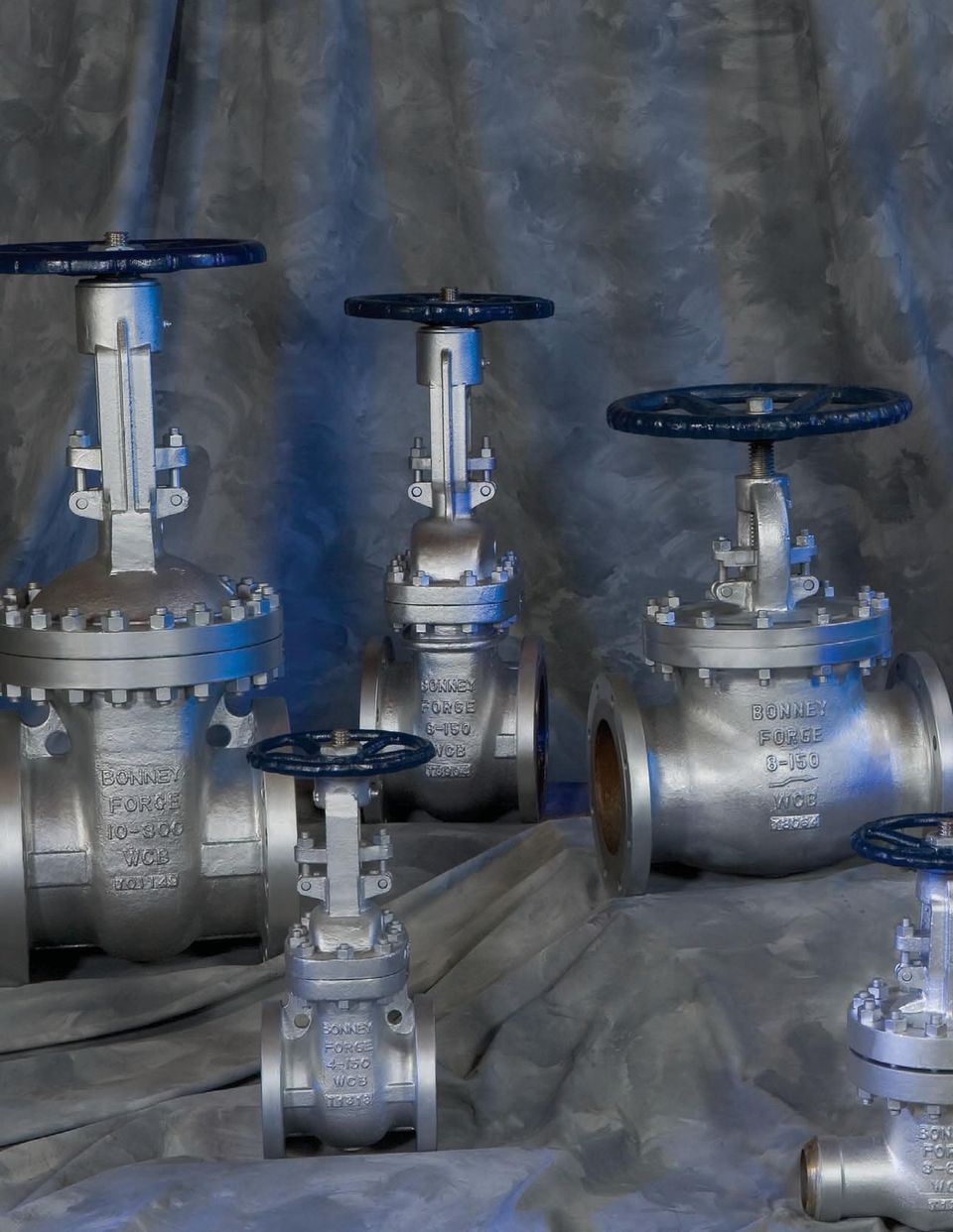
2 CST STEEL VLVES

3 SBP LIMITED Bonney Forge Venture Company SBP LIMITED IS BONNEY FORGE JOINT VENTURE COMPNY 0 XINGHUQIO ROD (E) QUINGPU SHNGHI CHIN 707 BONNEY FORGE CORPORTE HEDQURTERS MNUFCTURING/SLES CENTER/WREHOUSE 9 CROGHN PIKE P.O. BOX 0 MT. UNION, P 70 () (00) (00) 7 FX () bfsales@bonneyforge.com BONNEY FORGE CORPORTE HEDQURTERS MT. UNION, P
 (00) (00) 7 FX () 9977 www.bonneyforge.com bfsales@bonneyforge.")
4 TBLE OF CONTENTS Corporate Overview..., Quality ssurance..., How To Order... Gate Valves...9 Globe Valves... Swing Check Valves...7 Engineering Specifications...9 Special Valves & Features..., 9 Bypass & Drain Connection... ButtWelding Ends... Flange Dimensions..., Ring Joint Facings..., Standard Class Pressure Temperature Ratings... Storage, Installation & Maintenance...9 Terms & Conditions... 7

5 Bonney Forge The Name You Can Trust for Cast Valves For decades, Bonney Forge forged steel valves and piping components have defined stateoftheart in quality, design and manufacturing. Today, our extensive product line of cast steel valves leads the way. Since 0, Bonney Forge has been manufacturing its Cast Valves in Shanghai, China. SBP Limited Bonney Forge Venture Company, manufactures a full line of Cast Gate, Globe and Check Valves designed for SME pressures 0# thru 00# and temperature ratings as low as 0 F. Our technicians can also customize a configuration to fit your needs. Bonney SINGLESOURCE SOLUTION Forge customers have a complete choice of trim and body materials, bypasses and connectors including: lift indicators, limit microswitches, pneumatic and electric actuators, bevel gearings, chain wheels, extension stems, floor stands, levers and dashpots. SBP Limited also meets stringent design and quality guidelines set and directed by Bonney Forge s corporate engineering department at its corporate location in Mt. Union, Pennsylvania, US. SBP Limited has also earned the ISO 900:0, PED CE Mark, PI D, and PI 00 Certificates. We re Here for You Bonney Forge is coitted to manufacturing excellence and is focused on meeting our customers needs. This catalog offers a vast amount of product information and specifications. In the event that you need additional information or technical assistance please call our friendly and knowledgeable customer service team at (00) or visit our website at Our Mission To be, today and in the future, the recognized leader in our industry, marketing and manufacturing forged steel valves, cast steel valves, forged fittings, branch connections and other related products to satisfy our customer s expectations. To be cost effective through Total Quality performance of these operations, and thus provide the resources required to support our coitment to improve our products, processes and customer services. To be a law abiding corporate citizen respecting the rights of individuals, contributing to the needs of the counity and conserving the state of the environment.

6

7 QULITY SSURNCE Testing Bonney Forge products are manufactured and tested in strict accordance to STM, SME, PI and other industry codes and specifications as applicable. Material Certifications are available upon request to the applicable STM/SME material specifications for all Bonney Forge Valve bodies and bonnets. Modern machining equipment plus rigid inspection procedures of all parts assures dimensional accuracy of every part. Quality ssurance procedures include, 0% hydrostatic and pneumatic testing of all valves in full conformance to applicable PI standards and industry codes. Chemical and mechanical properties of every Bonney Forge cast steel valve are fully traceable to the original casting heat lot. Material Safety Data Sheets Material Safety Data Sheets (MSDS) are required for hazardous chemicals under the Occupational Safety and Health dministration (OSH) Hazard Counication Standard 9 CFR 9.. Bonney Forge Corporation has determined that its valve and fitting products are articles, as defined by this standard, and therefore do not require material safety data sheets. Certificates lso, SBP limited is fully qualified and maintains the ISO 900 0, PED CE Mark, PI D and PI 00 certifications, as indicated below. Manufacturing Capabilities

8 The SBP Limited facilities are located in Shanghai, China and are in full accordance with ISO 900 and CE Mark certifications.

9 HOW TO ORDER/SPECIFY CST STEEL VLVES. Specify valve size. Designate Bonnet Style and Pressure Class from Section. Select Valve Type desired from Section B. Indicate Body/Bonnet and Trim Material from Section C. Select End Configuration from Section D. Select other Body/Bonnet/Trim from Section E 7. Select Special Requirement(s) from Section F. Specify as a Suffix String, after Section D or E, any Body/Bonnet Material, Trim Material or Special Requirements not listed below SECTION BONNET STYLE ND PRESSURE CLSS Bolted Bonnet Class 0# Bolted Bonnet Class 00# Bolted Bonnet Class 00# 9 Bolted Bonnet Class 900# Bolted Bonnet Class 00# Note: Pressure Seal Bonnet design available upon request SECTION B TYPE OF VLVE Gate Valve, Flexible Wedge Globe Valve, T Pattern Check Valve, Swing Type

10 SECTION C BODY/BONNET ND TRIM MTERIL WCB Body/Bonnet, Trim % Cr (F/C) Hard Faced Seats ( Stellite) PI Trim # N WCB Body/Bonnet, Trim % Cr (F/C) PI Trim # WCB Body/Bonnet, Trim % Cr (F/C) Hard Faced Seats & Disc (Full Stellite) PI Trim # WCB Body/Bonnet, Trim % CrNI (/CFM) PI Trim # WCB Body/Bonnet, Trim NiCu lloy, (Monel Metal) PI Trim #9 7WC9 Body/Bonnet, /% Cr % Mo, Trim % Cr (F/C) Hard Faced Seats ( Stellite) PI Trim # 7C Body/Bonnet, % Cr % Mo, Trim % Cr (F/C) Hard Faced Seats ( Stellite) PI Trim # 7 CF Body/Bonnet, Trim % Cr Ni(0/CF) Trim 0 Stainless PI Trim # CFM Body/Bonnet, Trim % Cr Ni(/CFM) Trim Stainless PI Trim # S CFM Body/Bonnet, Trim % Cr Ni(/CFM) Trim Stainless, Hard Faced Seats ( Stellite) PI Trim # 9 7WC Body/Bonnet, /% Cr Mo, Trim % Cr (F/C) Hard Faced Seats ( Stellite) PI Trim # 0 Other Specify SECTION D END CONFIGURTION RF RTJ BW Raised Face, Flanged End, 0 RH Ring Type Joint Butt Weld Ends (Specify Pipe Schedule) SECTION E OTHER BODY/BONNET OR TRIM MTERILS C 7C 9% Cr % Moly C 7C % Cr Moly LCB/LCC LCB Low Temp Carbon 0 F CF CF Stainless, Type 0L Note: Other body/bonnet/trim materials available upon request 7
 Trim Stainless PI Trim # S CFM Body/Bonnet, Trim % Cr Ni(/CFM) Trim Stainless, Hard Faced Seats ( Stellite) PI Trim # 9 7WC Body/Bonnet, /% Cr Mo, Trim % Cr (F/C) Hard Faced Seats (")
11 HOW TO ORDER/SPECIFY CST STEEL VLVES SECTION E VILBLE TRIM MTERILS TRIM PI 00 TRIM No. 9 Seating Surface Wedge Check Disc Seat Ring Monel Stellite Stellite Stellite Globe Disc F F F F F0 Monel F Seat Ring Monel Stellite Stellite Back Seat Stem Hinge Pin F F F LLOY Stellite Stellite F F F F F0 F SECTION F MODIFICTIONS/SPECIL REQUIREMENTS BG BYP CWO CRY EMO GD NCE PMI Bevel Gear Operator Bypass Chainwheel Operated Cryogenic Bonnet Electric Motor Operator Guided Disc (Globe Valves) NCE Requirements to MR0, latest edition Positive Material Identification required List as a suffix, by abbreviation if possible, any other requirement not shown on this list Example: " 0# RF Flanged Gate Valve, Bolted Bonnet, STM WCB Body/Bonnet with Stellite Trim RF Sec Sec. B, Sec. C Sec. D S: " RF
 NCE Requirements to MR0, latest edition Positive Material Identification required List as a suffix, by abbreviation if possible, any other requirement not shown on this list Example: \" 0#")
12 GTE VLVES CLSS 0 Design construction: PI 00, SME B. Pressure Temperature Rating SME B. Face to Face / End to End SME B. Connection SME B. / B. Testing and Inspection PI 9 MTERILS OF CONSTRUCTION ITEM DESCRIPTION MTERIL Body Seat Ring Wedge Stem Bonnet Bolt Bonnet Nut Gasket Bonnet Back Seat Packing Eye Bolt Pin Gland Eye Bolt Packing Gland Flange Gland Eye Bolt Nut Grease Nipple Yoke Sleeve Sleeve Nut Handwheel Handwheel Nut Set Screw Yoke Yoke Nut Yoke Bolt Bearing WCB + Stellite WCB / % CR. F 9 B7 9 H Graphite Corrugated WCB F Graphite 9 GR. B7 Fa WCB 9 GR H 9 GR D Ductile Iron WCB 9 GR. H 9 GR B7 D I M E N S I O N L S P E C I F I C T I O N S SIZE L L L W W H (OPEN) H (GER) WT (RF) WT (BW) WT (RF & GO) WT (BW & GO) CV Factors

13 GTE VLVES CLSS 00 Design construction: PI 00, SME B. Pressure Temperature Rating SME B. Face to Face / End to End SME B. Connection SME B. / B. Testing and Inspection PI 9 MTERILS OF CONSTRUCTION ITEM DESCRIPTION MTERIL Body Seat Ring Wedge Stem Bonnet Bolt Bonnet Nut Gasket Bonnet Back Seat Packing Eye Bolt Pin Gland Eye Bolt Packing Gland Flange Gland Eye Bolt Nut Grease Nipple Yoke Sleeve Sleeve Nut Handwheel Handwheel Nut Set Screw Yoke Yoke Nut Yoke Bolt Bearing WCB + Stellite WCB / % CR. F 9 B7 9 H Spiral S.S. Graphite WCB F Graphite 9 GR. B7 F WCB 9 H 9 GR. D Ductile Iron WCB 9 GR. H 9 GR. B7 D I M E N S I O N L S P E C I F I C T I O N S SIZE L L L W W H (OPEN) H (GER) WT (RF) WT (BW) WT (RF & GO) WT (BW & GO) CV Factors

14 GTE VLVES CLSS 00 Design construction: PI 00, SME B. Pressure Temperature Rating SME B. Face to Face / End to End SME B. Connection SME B. / B. Testing and Inspection PI 9 MTERILS OF CONSTRUCTION ITEM DESCRIPTION MTERIL Body Seat Ring Wedge Stem Bonnet Bolt Bonnet Nut Gasket Bonnet Back Seat Packing Eye Bolt Pin Gland Eye Bolt Packing Gland Flange Gland Eye Bolt Nut Grease Nipple Yoke Sleeve Sleeve Nut Handwheel Handwheel Nut Set Screw Yoke Yoke Nut Yoke Bolt Bearing WCB + Stellite WCB / % CR. F 9 B7 9 H Soft Iron WCB F Graphite 9 GR. B7 F WCB 9 H 9 GR. D Ductile Iron WCB 9 GR. H 9 GR. B7 D I M E N S I O N L S P E C I F I C T I O N S SIZE L L L W W 0 0 H (OPEN) H (GER) WT (RF) WT (BW) WT (RF & GO) WT (BW & GO)...00 CV Factors

15 GLOBE VLVES CLSS 0 Design construction: SME B. Pressure Temperature Rating SME B. Face to Face / End to End SME B. Connection SME B. / B. Testing and Inspection PI 9 MTERILS OF CONSTRUCTION ITEM DESCRIPTION MTERIL Body Seat Ring Disc Disc Thrust Plate Disc Stem Nut Stem Gasket Bonnet Back Seat Packing Bonnet Bolt Bonnet Nut Eye Bolt Pin Packing Gland Gland Eye Bolt Gland Flange Eye Bolt Nut Yoke Sleeve Set Screw Handwheel Washer Handwheel Nut WCB + Stellite # / % CR. F F F Spiral S.S. Graphite WCB F Graphite 9 B7 9 H F 9 B7 WCB 9 H 9 GR. D Ductile Iron D I M E N S I O N L S P E C I F I C T I O N S SIZE L L L W W H (OPEN) H (GER) WT (RF) WT (BW) WT (RF & GO) WT (BW & GO) CV Factors 0 0 0

16 GLOBE VLVES CLSS 00 Design construction: SME B. Pressure Temperature Rating SME B. Face to Face / End to End SME B. Connection SME B. / B. Testing and Inspection PI 9 MTERILS OF CONSTRUCTION ITEM DESCRIPTION MTERIL Body Seat Ring Disc Disc Thrust Plate Disc Stem Nut Stem Gasket Bonnet Back Seat Packing Bonnet Bolt Bonnet Nut Eye Bolt Pin Packing Gland Gland Eye Bolt Gland Flange Eye Bolt Nut Yoke Sleeve Set Screw Handwheel Washer Handwheel Nut WCB + Stellite # / % CR. F F F Spiral S.S. Graphite WCB F Graphite 9 B7 9 H F 9 B7 WCB 9 H 9 GR. D Ductile Iron D I M E N S I O N L S P E C I F I C T I O N S SIZE L L L W W H (OPEN) H (GER) WT (RF) WT (BW) WT (RF & GO) WT (BW & GO) CV Factors
.")
17 GLOBE VLVES CLSS 00 Design construction: SME B. Pressure Temperature Rating SME B. Face to Face / End to End SME B. Connection SME B. / B. Testing and Inspection PI 9 MTERILS OF CONSTRUCTION ITEM DESCRIPTION MTERIL Body Seat Ring Disc Disc Thrust Plate Disc Stem Nut Stem Gasket Bonnet Back Seat Packing Bonnet Bolt Bonnet Nut Eye Bolt Pin Packing Gland Gland Eye Bolt Gland Flange Eye Bolt Nut Yoke Sleeve Set Screw Handwheel Washer Handwheel Nut WCB + Stellite # / % CR. F F F Soft Iron WCB F Graphite 9 B7 9 H F 9 B7 WCB 9 H 9 GR. D Ductile Iron D I M E N S I O N L S P E C I F I C T I O N S SIZE L L L W W 0 0 H (OPEN) H (GER) WT (RF) WT (BW) WT (RF & GO) WT (BW & GO) CV Factors 0
 7.")
18 CHECK VLVES CLSS 0 Design construction: SME B. Pressure Temperature Rating SME B. Face to Face / End to End SME B. Connection SME B. / B. Testing and Inspection PI 9 MTERILS OF CONSTRUCTION ITEM DESCRIP MTERIL Body Seat Ring Disc Hinge Washer Disc Nut Pin Hinge Pin Yoke Hinge Bolt Washer Spring Washer Cover Bolt Gasket Cover Cover Nut Eye Bolt Bolt Nut Cap Gasket WCB + Stellite / % CR. WCB S.S. S.S. F WCB F0 9 GR. B7 Spiral S.S. Graphite WCB 9 GR. H 9 GR. B7 9 GR. H S.W. + Graphite D I M E N S I O N L S P E C I F I C T I O N S SIZE L L L H WT (RF) WT (BW) CV Factors

19 CHECK VLVES CLSS 00 Design construction: SME B. Pressure Temperature Rating SME B. Face to Face / End to End SME B. Connection SME B. / B. Testing and Inspection PI 9 MTERILS OF CONSTRUCTION ITEM DESCRIP MTERIL Body Seat Ring Disc Hinge Washer Disc Nut Pin Hinge Pin Yoke Hinge Bolt Washer Spring Washer Cover Bolt Gasket Cover Cover Nut Eye Bolt Bolt Nut Cap Gasket WCB + Stellite / % CR. WCB S.S. S.S. F WCB F0 9 GR. B7 Spiral S.S. Graphite WCB 9 GR. H 9 GR. B7 9 GR. H S.W. + Graphite D I M E N S I O N L S P E C I F I C T I O N S SIZE L L L H WT (RF) WT (BW) CV Factors
.9.7 9 0.00. 0.00 90 0.")
20 CHECK VLVES CLSS 00 Design construction: SME B. Pressure Temperature Rating SME B. Face to Face / End to End SME B. Connection SME B. / B. Testing and Inspection PI 9 MTERILS OF CONSTRUCTION ITEM DESCRIP MTERIL Body Seat Ring Disc Hinge Washer Disc Nut Pin Hinge Pin Yoke Hinge Bolt Washer Spring Washer Cover Bolt Gasket Cover Cover Nut Eye Bolt Bolt Nut Cap Gasket WCB + Stellite / % CR. WCB S.S. S.S. F WCB F0 9 GR. B7 Soft Iron WCB 9 GR. H 9 GR. B7 9 GR. H S.W. + Graphite D I M E N S I O N L S P E C I F I C T I O N S SIZE L L L H WT (RF) WT (BW) CV Factors
 7.")
21 ENGINEERING SPECIFICTIONS SPECIL FETURES LIFT INDICTOR LIMIT MICRO SWITCHES PNEUMTIC OPERTOR BEVEL GERING BEVEL GERING WITH HORIZONTL HNDWHEEL ELECTRIC CTUTOR
22 EXTENSION STEM FLOOR STND FLOOR STND WITH UNIVERSL JOINT CHIN WHEEL CHECK VLVE WITH DSH POT CHECK VLVE WITH OUTSIDE LEVER & WEIGHT 9
23 ENGINEERING SPECIFICTIONS BYPSS & DRIN CONNECTION (on the same side as E & F) I J K H F C C B C G B D B E C D E & F F E B F B C F E D E NGLE VLVE D G C E CHECK VLVE B D G F C E G GTE VLVE D F & B C GLOBE VLVE D These illustrations show the location of tapped holes. When placing an order please quote the letters in the above illustrations designating the location of the tapped holes. For more information see MSSSP. DRIN & BYPSS DIMENSIONS J T THRED FOR CONNECTION TPPING SOCKET WELDING FOR CONNECTIONS BOSSES FOR CONNECTIONS Size of Valve. " to " " to " " to " Size of Tapping / Length of Thread T 9/ 9/ / Minimum Diameter of Socket 7/ / Minimum Depth of Socket B / / / Diameter of Boss J / / ll dimensions given in es Bonney Forge valves can be equipped with bypasses which permit equalization of pressure on both sides of the valve. Unless otherwise specified the bypass arrangement will be furnished on the side of the main valve. Bypasses of other types can be made to order. Inquiries should give complete description or drawings. Bypass valves are Bonney Forge forged steel boltedbonnet, outside screw and yoke, socketweld end globe valves, and materials are suitable for the same service as the main valve.
24 ENGINEERING SPECIFICTIONS Nominal Pipe Size Nominal Pipe OD Schedule Number Valve OD Nominal ID B Wall Thickness of Pipe T BUTTWELDING ENDS SME B. 7 / ± / 0 / 0 / R / t 7 / ± / / R / t ± Figures refer to SME B / ± / B / ± / IMPORTNT: When ordering butt welding end valves please state the type of ends required and give the pipe dimensions or schedule number. B / XXS XXS XXS XXS XXS XXS STD 0 XS STD 0 XS STD / / / / / / / / STD = Standard Wall Thickness XS = Extra Strong Wall Thickness XXS = Double Extra Strong Wall Thickness ll dimensions given in es Designations per SME B /
25 ENGINEERING SPECIFICTIONS FLNGE DIMENSIONS SME B. and MSSSP SME 0 Nominal Pipe Size / / Flange Diameter Flange Thickness Companion Flange B 7/ 9/ / / 7/ / / / / 7/ 9/ / 7/ Valve Flange B 7/ 9/ / / / Diameter of Raised Face C / / 7/ / / 7 / / 7 / Diameter of Bolt Circle D / / / 7/ / / / 7 / / / 9 Diameter of Bolt Holes E / / / / / 7/ 7/ 7/ / / / / / Number of Bolts Diameter of Bolts / / / 7/ 7/ / / / The regular / raised face of 0. flanges is included in the minimum flange thickness given, but other raised faces must be added thereto. The bolt holes, which are in multiples of four, are drilled to straddle the centerline unless otherwise ordered. 0 / / / / / 7/ 9/ / 7/ 9 / / 0 / / / SME 00 0 / / / 0 / / 7/ / / 7 / / 7/ 9/ / 9/ / / 7/ / / / / 7/ 7/ / / / / 0 / / / 7 / / 7/ / / 7 / / 7 / / / 7 / 9 / 7/ 7/ 7 / 7 7/ 9 / / 7 / / / 7 / / / 7/ / 7/ 7/ 7/ 7/ 7/ 7/ / / / / / / / / / / / / / 7/ / / / / / The regular / raised face of 00. flanges is included in the minimum flange thickness given, but other raised faces must be added thereto. The bolt holes, which are in multiples of four, are drilled to straddle the centerline unless otherwise ordered. 0 / 0 / / 7 / / 7/ 9 / 7 9 / / / 7/ / 7/ 7/ 0 0 / / / 0 / 0 / / / End Flange dimensions comply with SME B. and MSSSP ll dimensions are in es
26 0 & 00. E 00, 00, 900, 00 & 00. E B B /" C D /" C D Nominal Pipe Size Flange Diameter Flange Thickness Diameter of Raised Face C Diameter of Bolt Circle D Diameter of Bolt Holes E Number of Bolts Diameter of Bolts / / / 7/ / / 7 / 9 / 9/ / / 7/ / / / / / 7/ / / / 7/ 7/ 7 / / / / 7/ / 7/ 7/ / / 7/ 7/ The regular / raised face of 00. flanges is not included in the minimum flange thickness given. The bolt holes, which are in multiples of four, are drilled to straddle the centerline unless otherwise ordered. SME 00 / 7 9 / 7 / 7/ / / / 7 / / 7 / / 7 9 / / / / / / / / / / / / / / / 7/ 0 0 / 7 9 / / / / 7/ 9 / 0 / 0 7 / / / / 7/ / / SME / / 7 / / / / / / / 7 / / 7 9 / / 7 / / / / 7/ / / / / / / 7/ Use 00. dimensions in sizes smaller than. / / / 7 / 9 / End Flange dimensions comply with SME B. and MSSSP ll dimensions are in es
27 ENGINEERING SPECIFICTIONS RING JOINT FCINGS B OVL RING SME B. and B. H OCTGONL RING C D Groove suitable for either Oval or Octagonal ring Nominal Pipe Size Ring Number Ring Width Oval Ring Height B Groove Width D Octagonal Ring Height H Ring Joint Raised Face Diameter K Groove Depth L Ring & Groove Pitch Diameter P / R R7 R9 R 9/ 9/ 9/ 9/ / / / / 7/ / / / / / 7/ / 9/ / 0 LB. R R9 R R0 R R R R 9/ 9/ 9/ 9/ 9/ 9/ 9/ 9/ / / / / / / / / / / / 7 / / / / / / / / / 7/ / 7 9 / R9 R R R7 R7 9/ 9/ 9/ 9/ 9/ / / / / / / 9 / / / / / 7 7/ / / / R R R R / 7/ 9/ 9/ 9/ 9/ / / / / / / 7/ / / / / / / 00, 00 LB. R R R R R7 R R R9 R R7 R R 7/ 7/ 7/ 7/ 7/ 7/ 7/ 7/ 7/ 7/ 7/ 9/ / / / / / / / / / / / / / / / / / / / / / / / 9/ / / 7/ / 9 7/ / / / / 7/ 7/ 7 / / R9 R7 R77 7/ / / 7/ / 7/ / / / 9 / 7/ 7 / ll dimensions are in es
28 Nominal Pipe Size Ring Number Ring Width Oval Ring Height B Groove Width D Octagonal Ring Height H Ring Joint Raised Face Diameter K Groove Depth L Ring & Groove Pitch Diameter P R R7 R R 7/ 7/ 7/ 7/ / / / / / / / / / 7 / 9 7/ 7/ 7 / 900 LB. R9 R R7 R 7/ 7/ 7/ / / / 7/ / / / / / / / / 7/ / R R70 R7 R7 / / 7/ / / / / / / / 0 / 7/ 7 / / / R R R R 9/ 9/ 9/ 9/ / / / / / / / / / / / / 9/ / / R R R7 R 7/ 7/ 7/ 9/ / / / / / / / 7/ / / / / / / 00 LB. R9 R R R0 7/ 7/ / / / 7/ / / 7/ / / / / / 7/ / 7 / R R R R7 7/ / 7/ / 7/ / 9/ / / / / / / 7 / 9 / 7/ 9/ / / R7 R7 R79 / / / 7/ 9/ / / 7/ / / / / / / 7 / ll dimensions are in es
29 ENGINEERING SPECIFICTIONS STNDRD CLSS PRESSURE TEMPERTURE RTINGS SME B. Working Class by Pressures Temperature, F WCB(a) LCB(d) WCC(a) LC(d) LC(d) LCC(e) 7 WC(b) LC(d) 7 WC(h) 7 WC(i) 7 WC(j) 7 WC9(j) 7 C 7 C CF(f) CF CFM(g) CFM CFC CN7M(l) Working Pressures in PSI 0 LB. to () 0 () 0 () 0 () 0 () 0 () 0 () 0 () () () () () () () () () () () () () () () () () () () () () () () () () () () () () () () () () () () () () () () () 00 LB. to
30 7 Working Class by Pressures Temperature, F WCB(a) LCB(d) WCC(a) LC(d) LC(d) LCC(e) 7 WC(b) LC(d) 7 WC(h) 7 WC(i) 7 WC(j) 7 WC9(j) 7 C 7 C CF(f) CF CFM(g) CFM CFC CN7M(l) Working Pressures in PSI 00 LB. to LB. to
31 ENGINEERING SPECIFICTIONS STNDRD CLSS PRESSURE TEMPERTURE RTINGS SME B. Working Class by Temperature, Pressures F WCB(a) LCB(d) WCC(a) LC(d) LC(d) LCC(e) 7 WC(b) LC(d) 7 WC(h) 7 WC(i) 7 WC(j) 7 WC9(j) 7 C 7 C CF(f) CF CFM(g) CFM CFC CN7M(l) Working Pressures in PSI 00 LB. to NOTE: () For welding end valves only. Flanged end ratings terminate at 00 F. NOTES: (a) Permissible, but not recoended for prolonged usage above about 00 F. (b) Permissible, but not recoended for prolonged usage above about 0 F. (d) Not to be used over 0 F. (e) Not to be used over 700 F. (f) Not to be used over 00 F. (g) Not to be used over 0 F. (h) Not to be used over 00 F. (i) Not to be used over 0 F. (j) Not to be used over 0 F. (l) Ratings apply for 00 F and lower.
32 STORGE, INSTLLTION ND MINTENNCE PROCEDURES GTE VLVE O.S. & Y.0 Periodic Inspections. The valve stem packing should be inspected at least monthly. If the stem packing shows signs of leakage, simply tighten the adjusting nuts to compress the packing. Do not overtighten the adjusting nuts as this will make operation of the valve more difficult. If, after tightening the adjusting nuts to their fullest extent, the leakage does not stop, it is then necessary to replace the stem packing. It is not recoended that additional packing rings be added to the stuffing box as this may cause damage to the stem sealing system. Please contact Bonney Forge or it s distributor for new stem packing sets. For packing replacement see paragraphs. and... The lubrication of the yoke nut should be inspected at least monthly. high pressure grease gun should be used for valves supplied with ball type grease fittings. For valves supplied with a Stauffer type grease cup, the cup should be checked to assure that it is full so that the grease can be injected by turning the screw cap. The valve stem threads should also be given a coating of lubricant.. Bonnet bolt tension should be checked periodically when valves are used in high temperature applications where creep may occur. lthough leaks through ring joints are rare, erosion or corrosion could cause rings to fail. In these cases, a new ring gasket is required..0 Extraordinary Maintenance or Replacement of Damaged Parts. Stem. If the stem locks or "freezes", causes can generally be attributed to worn packing, a dry yoke nut or dry stem threads. In either of these cases, the following service is required: a*) Unscrew gland nuts, remove the gland flange and bushing to expose stem packing and lantern ring. Replace stem packing if it is damaged. b) Check lubrication of yoke nut. If it is dry, remove the yoke nut and determine if there is evidence of seizure marks. If so, replace it with a new yoke nut. lso check the nut and stem threads.. Disassembly of Stem Packing.* a) In those cases where the valve can not be removed from the piping system, it is important that prior to servicing, the valve be opened to its fullest extent. Partially unscrew nuts to reduce the compression load on the stuffing box. Remove the stem packing and then replace with new set(s) of packing. Finally, tighten nuts sufficiently while allowing the stem to operate smoothly. b) To replace the stem when the valve is completely disassembled for general maintenance follow this procedure: Open the valve half way and remove bonnet bolts and nuts. Lift up the bonnet to remove the wedge. With the bonnet removed, unscrew the gland bolts and lift up the gland flange exposing the stem packing. Remove the stem packing. Remove the stem through the stuffing box. *CUTION: lways be sure that the valve is depressurized and isolated prior to performing any maintenance work. 9
33 STORGE, INSTLLTION ND MINTENNCE PROCEDURES GTE VLVE O.S. & Y (CONTINUED). The procedure to reassembly the valve is as follows: Reinsert the stem through the stuffing box taking special care to reassemble parts in sequence. Insert the remaining packing rings into the stuffing box and compress using the gland and flange. Then, reassemble nuts and tighten. Note, the stem must slide freely through the stuffing box without applying excessive force. Finally, install the bonnet gasket making sure it is not damaged. The gasket should be replaced if there is any question as to its performance.. Raise the bonnet, making sure the stem is in a half open position, then connect disc to stem. Lower bonnet on to the valve body making sure that the disc fits exactly into body guides and the bonnet gasket is properly seated. lign holes and tighten bonnet nuts taking care that excessive force is not used, possibly damaging the gasket. Hydrostatically test the valve to assure that there is no leakage.. Disassembly of yoke nut When necessary use the following procedure for disassembling and replacing yoke nut: a) direct handoperated valves (handwheel) remove set screw; unscrew handwheel nut; remove handwheel; unscrew yoke nut retaining nut, removing spot welds if necessary; Reverse the procedure for reassembly. b) bevel gear operated valves to remove the bevel gear from the valve, unscrew nuts and turn the handwheel in the open direction indicated by the arrow until the drive nuts are disengaged from the stem. to check the condition of the drive nut or bearing, unscrew the retainer ring and remove the drive nut and bearing. If damaged, a new drive nut or bearing is necessary.. Wedge and Seats Leakage through seats and wedges is not always easy to spot when valves are in service. However, when leaks are identified, iediate action is necessary. ny delay can permanently damage seat or wedge seal surfaces. To repair or replace wedges or seats, the valve must be removed from the line and the following procedure should be applied: make sure that the valve is not under pressure before unscrewing bonnet nuts; remove the bonnet, being careful not to damage the gasket; remove the bonnet when the wedge is in the half open position; lift up the bonnet until the wedge is disconnected from the guides; release the wedge from the stem. If seat surfaces show signs of seizing, pitting, grooves or other defects not deeper that 0. (/") it is possible to repair seating surfaces to its original conditions by relapping the surface with line grain abrasive paste, creating a perfect tightness once again. Defects having a depth exceeding 0. (/") cannot be repaired by lapping. In this case, parts must be replaced. It is recoended that the face of the disc be blued to check for contact of seating surface after final lapping. For reassembly of valves use the procedure outlined under para... 0
34 GLOBE VLVE O.S. & Y.0 Periodic Inspections. The valve stem packing should be inspected at least monthly. If the stem packing shows signs of leakage, simply tighten the adjusting nuts to compress the packing. Do not overtighten the adjusting nuts as this will make operation of the valve more difficult. If, after tightening the adjusting nuts to their fullest extent, the leakage does not stop, it is then necessary to replace the stem packing. It is not recoended that additional packing rings be added to the stuffing box as this may cause damage to the stem sealing system. Please contact Bonney Forge or it s distributor for new stem packing sets. For packing replacement see paragraphs. and... The lubrication of the yoke nut should be inspected at least monthly. high pressure grease gun should be used for valves supplied with ball type grease fittings. For valves supplied with a Stauffer type grease cup, the cup should be checked to assure that it is full so that the grease can be injected by turning the screw cap. The valve stem threads should also be given a coating of lubricant.. Bonnet bolt tension should be checked periodically when valves are used in high temperature applications where creep may occur. lthough leaks through ring joints are rare, erosion or corrosion could cause rings to fail. In these cases, a new ring gasket is required..0 Extraordinary Maintenance or Replacement of Damaged Parts. Stem. If the stem locks or freezes, causes can generally be attributed to worn packing, a dry yoke nut or dry stem threads. In either of these cases, the following service is required: a*) Unscrew gland nuts, remove gland flange and bushing to expose stem packing and lantern ring. Replace stem packing if it is damaged. b) Check lubrication of yoke nut. If it is dry, remove the yoke nut and determine if there is evidence of seizure marks. If so, replace it with a new yoke nut. lso check the nut and stem threads.. Disassembly of Stem Packing.* a) In those cases where the valve cannot be removed from the piping system, it is important that prior to servicing, the valve be opened to its fullest extent. Partially unscrew nuts to reduce the compression load on the stuffing box. Remove the stem packing and then replace with new set(s) of packing. Reassemble plug and gland flange. Finally, tighten nuts sufficiently while allowing the stem to operate smoothly. b) To replace the stem when the valve is completely disassembled for general maintenance follow this procedure: Open the valve and remove the bonnet bolts and nuts. With the bonnet removed, unscrew the gland bolts and lift up the gland flange exposing the stem packing. Remove the stem packing. Remove handwheel, then turn stem to release it from yoke nut and remove from stuffing box. Check condition of backseat bushing for seizure marks. If apparent, order replacement parts. *CUTION: lways be sure that the valve is depressurized and isolated prior to performing any maintenance work.
35 STORGE, INSTLLTION ND MINTENNCE PROCEDURES GLOBE VLVE O.S. & Y (CONTINUED). The procedure to reassembling the valve is as follows: Reinsert the stem through the stuffing box, taking special care to reassemble parts in sequence. Insert the remaining packing rings into the stuffing box and compress using the gland ring and flange. Then, reassemble nuts and tighten. Note, the stem must slide freely through the stuffing box without applying excessive force. Finally, install the bonnet gasket making sure it is not damaged. The gasket should be replaced if there is any question as to its performance.. Raise the bonnet assembly, making sure the stem is in the fully open position. Lower bonnet on to the valve body making sure that the disc fits exactly into body guides and the bonnet gasket is properly seated. lign holes and tighten bonnet nuts taking care that excessive force is not used, possibly damaging the gasket. Hydrostatically test the valve to assure that there is no leakage.. Disassembly of yoke nut When necessary use the following procedure for disassembling and replacing yoke nut: a) direct handoperated valves (handwheel) remove set screw; unscrew handwheel nut; remove handwheel; unscrew yoke nut retaining nut, removing spot welds if necessary; Reverse the procedure for reassembly. b) bevel gear operated valves to remove the bevel gear from the valve, unscrew nuts and turn the handwheel in the open direction indicated by the arrow until the drive nuts are disengaged from the stem. to check the condition of the drive nut or bearing, unscrew the retainer ring and remove the drive nut and bearing. If damaged, a new drive nut or bearing is necessary.. Disc and Seats Leakage through disc and seats is not always easy to spot when valves are in service. However, when leaks are identified, iediate action is necessary. ny delay can permanently damage seat or wedge seal surfaces. To repair or replace the disc or seats, the valve must be removed from line, then use the following procedure: make sure that the valve is not under pressure before unscrewing bonnet nuts; remove bonnet, being careful not to damage the gasket; remove bonnet when disc is in full open position; lift up bonnet If seat surfaces show signs of seizing, pitting, grooves or other defects not deeper that. (/") it is possible to repair seating surfaces to its original conditions by relapping the surface with line grain abrasive paste, creating a perfect tightness once again. Defects having a depth exceeding. (/") cannot be repaired by lapping. In this case, parts must be replaced. It is recoended that the face of the disc be blued to check for contact of seating surface after final lapping. For reassembly of valves use the procedure outlined under para...
36 SWING CHECK VLVES No periodic maintenance is necessary. If gasket leaks are detected, correct using the following procedure. Disassemble all cover bolts and nuts. For check valves in sizes " and larger, lift up the cover by using a lever inserted into the drilled and tapped cover hole. For valves in sizes " and smaller, use one or two bolts and nuts inserted into cover holes and, using adequate force, move the cover upwards. Check that the hinge, nut, and pin are in good condition and firmly connected. Replace damaged parts as necessary. Lift and remove the dischinge assembly. Movement should be free and not hindered by any malfunction of the hinge pin. Where disc travel is not sufficiently smooth, remove plugs or blind flanges and then remove hinge pin. Check surface for seizure marks. If marks are deeper than. (/"); remachine hinge pin and reassemble. If defect depth is greater than. (/") a new hinge pin is necessary. When reassembling hinge pin, it is recoended that the disc be removed by loosening nut. When leakage is due to deterioration of seal surfaces caused by corrosion or foreign substances, it must be determined whether the disc or seat seal are the cause. a) Deterioration of disc surfaces: Disassemble disc by removing nut and washer. Repair surface by grinding and relapping using fine grain abrasive paste. b) Deterioration of seat seal surfaces: When seal surfaces are damaged and defects are confined to a small area but are not deeper than 0. (/"), the seal surface can be repaired. The recoended method is to use a cast iron strap with an outside diameter matching the valve s raceway. Then using a fine grain abrasive paste between the strap and raceway, it is rotated on the seat to restore original tightness. When defects are deeper than 0. (/") and found on the entire seal surface, a new seat is required. To replace the new seat, use preferably a pneumatic tool with a shape to match the dimensions of the valve seat. It is recoended that an anti seizing compound be used when installing the replacement seat to make threading it in to the body easier. CUTION: lways be sure that the valve is depressurized and isolated prior to performing any maintenance work.
37 STORGE, INSTLLTION ND MINTENNCE PROCEDURES HNDWHEEL NUT HNDWHEEL YOKE SLEEVE RETINING NUT YOKE SLEEVE YOKE SLEEVE BERING NUT GLND FLNGE GLND NUT PCKING BCK SET BUSHING NUT EYE BOLT PIN BONNET STUD BOLT STEM WEDGE SET RING PLTE PLUG HNDWHEEL NUT HNDWHEEL YOKE SLEEVE RETINING NUT NUT GLND FLNGE GLND PCKING EYE BOLT BCK SET BUSHING PLUG PIN BONNET GSKET STEM DISC NUT HLF RING SET SCREW PLTE NUT BONNET STUD BOLT BONNET GSKET BODY NUT BONNET GSKET BODY NUT GTE VLVE COMPONENTS GLOBE VLVE COMPONENTS PIN BONNET GSKET PLUG PLUG GSKET SWING CHECK VLVE COMPONENTS STUD BOLT NUT BODY PLUG PLUG GSKET HINGE PIN PIN NUT DISC WSHER HINGE DISC DISC SET RING
38 NOTES
39 NOTES
40 WRRNTY EXCLUSIONS PURCHSER S REMEDIES PRICES CCEPTNCE OF ORDERS REMITTNCES PRTIL SHIPMENTS ND PYMENTS TXES SHORTGES & DMGES IN TRNSIT DELYS CNCELLTION & SUSPENSION RETURN OF MTERIL PTENTS GENERL TERMS ND CONDITIONS OF SLE OF: BONNEY FORGE (HEREFTER REFERRED TO S BF ) GOVERNING LW NO WIVER DIES, TOOLS ND PTTERNS FORCE MJEURE PURCHSER S CCEPTNCE OF BOVE CONDITIONS ll products are warranted to be free from manufacturing defects for a period of one () year from date of shipment, and any found to be defective within that period will be replaced without charge, provided () that the product was used as recoended and in accordance with approved installation and operating practices. () that its failure resulted from a manufacturing defect and not from damage due to corrosive, abrasive, or other wear normally to be expected in the services involved. () that the product was not modified or changed (unless written approval was give by BF), and () that written notice of such defect is delivered to BF during such one () year period. BF will not be responsible for any labor, equipment, engineering or related costs or liability associated with the replacement of a defective product. The Uniform Coercial Code shall not apply to the sale, nor the Michigan statutes adopting the Uniform Coercial Code. This express warranty is in lieu of and excludes all other warranties, guarantees, or representations, expressed or implied. There are no implied warranties of merchantability or of fitness for a particular purpose. Do not use BF products in aircraft or aerospace applications. No warranties, guarantees or representations of any kind are made with respect to such applications. The Purchaser assumes all risks of any use is such applications and will indemnify and hold harmless BF against and from any claims, costs (including attorneys fees) and liabilities arising out of such use. The Purchaser s remedies with respect to any product furnished by BF hereunder that is found not to be in conformity with the terms and conditions of the contract because of breach of contract, breach of express or implied warranty, or negligence shall be limited exclusively to the right of replacement of such defective product or, at our option, repayment of our sale price of the product. In no event shall BF be liable for claims (based upon breach of contract, breach of express or implied warranty, or negligence) for any other damages, whether direct, iediate, foreseeable, consequential, or special or for any expenses incurred by reason of the use or misuse, sale or fabrication of products which do or do not conform to the terms and conditions of the contract. Prices, and other terms of sale and payment, are subject to change without notice. Unless a contrary provision appears in this price schedule, quotation or order acknowledgment, prices may be withdrawn without notice at any time. Stenographic or clerical errors are subject to correction. ll orders are subject to BF credit department approval prior to acceptance by BF. No assignment of the Purchaser s rights may be made without the written consent of BF. ll accounts are payable in United States funds, free of exchange, collection or any other charges. If in the sole discretion of BF the financial condition of the Purchaser at any time so requires, BF retains the right to require full or partial payment in advance. BF reserves the right to make partial shipments from time to time and to render invoices therefore which shall be due and payable as provided in said invoices and the paragraph entitled. Remittances if the Purchaser becomes overdue in any such partial payment, BF shall be entitled to suspend work and or avail itself of other legal remedies. Unless otherwise specifically noted, the amount of any sale, use, occupancy, excise tax or other tax, of any nature, federal, state, or local for which BF is legally liable, either initially or through failure of payment by Purchaser, shall be added or be in addition to the price quoted and Purchaser agrees to pay the same to BF. Claims for shortages must be made in writing within ten days after receipt of shipment, but loss of or damage to material in transit is the responsibility of the carrier. ll promises of shipment are estimated as closely as possible, and we will use our best efforts to ship within the time promised but do not guarantee to do so, and assume no liability for no doing so. Materials stated to be in stock are subject to prior sale. The order or contract is subject to cancellation or instructions to suspend or delay work or delivery only upon receipt of written notification and with our consent, and upon agreement to pay BF s adjustment charge. Order s for special products ( usually price of application items) may be changed and or cancelled only upon receipt of written instructions with a facit understanding and agreement to make payment for material used and work already performed. No product of our manufacture may be returned without written consent. ll goods returned are subject to a handling charge plus freight in both directions and charges for any required reconditioning, unless otherwise specified in writing by BF. The Purchaser will indemnify and hold harmless BF against and from any claims, costs (including attorneys fees) and liabilities arising out of any suit alleging infringement of any United States by any product supplied by BF under the contract and made in accordance with the design and or specification furnished by the Purchaser to BF. The contract shall be governed by, construed, and enforced in accordance with the laws of the Coonwealth of Pennsylvania. The failure of BF to insist, in any one or more instances upon the performance of any of the terms, covenants, or conditions of the contract or to exercise any right thereunder shall not be construed as a waiver or relinquishment of the future performance of any such term, covenant or condition or the future exercise of such rights, nor shall it be deemed to be a waiver or relinquishment of any other term, covenant, or condition or the exercise of any other rights under the contract. Dies, tools and patterns required to produce the article quoted on shall remain the property of BF. Preparation charges for dies, tools and patterns represent only a portion of cost. Payment of such charge does not give you any right, title, or interest in such dies, tools, or other products of preparation. We will not be responsible for retention of dies or patterns on which no orders are received for two years or more. ny delays in or failure of performance of BF shall not constitute default or give rise to any claims for damages if and to the extent that such delay or failure is caused by occurrences beyond the control of BF, including but not limited to acts of God or the public enemy, expropriation or confiscation of facilities, compliance with any order or request of any governmental authority, acts of war, rebellion or sabotage or damage resulting therefrom, embargoes or other export restrictions, fires, floods, explosions, accidents, breakdowns, riots or strikes or other conceived acts of workmen, whether direct or indirect, or any other causes whether or not of the same class or kind as those specifically above named which are not within the control of BF and which by the exercise of reasonable diligence, BF, is unable to prevent or provide against. The contract shall be subject to the terms and conditions contained or referred to in BF s price schedule, quotation or order acknowledgment and to no others whatsoever. No waiver, alteration, or modification of the terms and conditions in this price schedule, quotation or order acknowledgment shall be binding unless in writing and signed by an authorized representative of BF. Note: The material in this catalog is for general information. For specific performance data and proper material selection, consult your Bonney Forge representative. lthough every attempt has been made to ensure that the information contained in this catalog is correct, Bonney Forge reserves the right to change designs, materials or specifications without notice. CVIM /0 Printed in U.S..
STORAGE, INSTALLATION AND MAINTENANCE PROCEDURES
 GATE VALVE O.S. & Y 1.0 Periodic Inspections 1.1 The valve stem packing should be inspected at least monthly. If the stem packing shows signs of leakage, simply tighten the adjusting nuts to compress the
Price List January 1, 2015
 Price List January 1, 2015 Cement Lined Price List Certification and General Installation Certification All Ductile Iron Spooling manufactured by is made in accordance with current ANSI/AWWA- C115/A21.15
PROTECTO 401 Price List
 Price List January 1, 2015 Protecto 401 Price List Certification and General Installation Certification All Ductile Iron Spooling manufactured by is made in accordance with current ANSI/AWWA- C115/A21.15
Installation, Operating and Maintenance Instructions for AEON Metal Seated Gate Valve (MSGV) Water
 Water") 1 Foreword 1.1 Thank you for choosing one of the range of AEON's BS standard valves. For safety purposes, the user shall read this instruction to fully understand the operation of the product. 2 AEON Design
1 Foreword 1.1 Thank you for choosing one of the range of AEON's BS standard valves. For safety purposes, the user shall read this instruction to fully understand the operation of the product. 2 AEON Design
These features have made Lo Torc valves the choice of high pressure plug value users, worldwide:
 LO TORC Plug Valve The high value, dependable performance, and low maintenance requirements of Halliburton Lo Torc valves can help reduce overall operating costs and help cut downtime. These features have
Crane Cast Steel Valves
 Crane Cast Valves Cast Valves General Index Ordering Information... 4 Materials... 5 General Data... 6 Identification... 7 General Features... 8 Gate Valve Features... 9 NACE Trim Valves...13 Globe Valve
Vogt Valves The Connection Bulletin for Extended Body Forged Steel Valves Welded Bonnet, Bolted Bonnet, Class 800 & Class 1500 CB 22
 The Connection Bulletin for Extended Body Forged Steel Valves Welded Bonnet, Bolted Bonnet, Class 800 & Class 1500 CB 22 Extended Body Forged Steel Valves An extended body gate valve specifically designed
NEWCO VALVES Newmans Inc., Newmans Valve Ltd. NEWCO/OIC Cast Valve Operation & Maintenance Manual
 NEWCO VALVES Newmans Inc., Newmans Valve Ltd. NEWCO/OIC Cast Valve Operation & Maintenance Manual TABLE OF CONTENTS 1. Introduction and Safety Information... 1 1.1. Introduction... 1 1.2. Safety Information...
SE-100-1, SE-200-1, SE-500-1, and SE-1000-1 AIR CHAMP PRODUCTS. User Manual SE BRAKE MODELS: (i) MTY (81) 83 54 10 18 ventas@industrialmagza.
 MTY (81) 83 54 10 18 ventas@industrialmagza.") AIR CHAMP PRODUCTS User Manual SE BRAKE MODELS: SE-00-, SE-200-, SE-500-, and SE-000- (i) FORM NO. L-20084-E-040 In accordance with Nexen s established policy of constant product improvement, the specifications
AIR CHAMP PRODUCTS User Manual SE BRAKE MODELS: SE-00-, SE-200-, SE-500-, and SE-000- (i) FORM NO. L-20084-E-040 In accordance with Nexen s established policy of constant product improvement, the specifications
RUBBER SLEEVE KNIFE GATE VALVE
 RUBBER SLEEVE KNIFE GATE VALVE The model knife gate is a wafer valve designed for a wide range of industrial applications. The double-seated design provides bi-directional shut off. The design of the valve
FLANGED END BALL VALVE
 Specification: FLANGED END BALL VALVE - Chem Oil s two-piece ball valve has been designed to handle extreme service applications with unsurpassed reliability. Valve body machined from solid wrought material
Terms and Conditions. 3012436v2 12285.01010
 Terms and Conditions ACCEPTANCE. Except as otherwise agreed in a written agreement signed by both parties, these Terms and Conditions will govern Buyer s purchase order. BI Technologies acceptance of Buyer
SINGLE STAGE INLINE FIRE PUMP
 MODEL 383 SINGLE STAGE INLINE FIRE PUMP INSTRUCTION AND REPAIR MANUAL NOTE! To the installer: Please make sure you provide this manual to the owner of the equip ment or to the responsible party who maintains
Fire Hydrant Troubleshooting
 Fire Hydrant Troubleshooting Pulsation or chatter during opening and flow of water from hydrant. Loose condition in stem at lower valve plate nut. Tighten lower valve plate nut and secure with SS lock
Fisher 1052 Size 20 Diaphragm Rotary Actuator with F and G Mounting Adaptation
 Instruction Manual 1052 Size 20 Actuator (F & G) Fisher 1052 Size 20 Diaphragm Rotary Actuator with F and G Mounting Adaptation Contents Introduction... 1 Scope of manual... 1 Description... 1 Specifications...
OPERATING and MAINTENANCE MANUAL SERIES 2700A CONTROL VALVE CONTENTS. INTRODUCTION...1 Scope...1 Description...1 Valve Identification...
 OPERATING and MAINTENANCE MANUAL SERIES 2700A CONTROL VALVE CONTENTS INTRODUCTION...1 Scope...1 Description...1 Valve Identification...2 1.0 VALVE INSTALLATION...2 2.0 VALVE MAINTENANCE...3 Actuator Disassembly...3
FIRE PROTECTION VALVES Price Sheet FPVLV-7.15 Effective: July 6, 2015 Cancels Price Sheet FPVLV-2.15 of February 2, 2015
 FIRE PROTECTION VALVES Price Sheet FPVLV-7.15 Effective: July 6, 2015 Cancels Price Sheet FPVLV-2.15 of February 2, 2015 FOR THE MOST CURRENT PRODUCT / PRICING INFORMATION ON ANVIL PRODUCTS, PLEASE VISIT
API Flanged Safety Relief Valves Series 526 CATALOG
 API Flanged Safety Relief Valves Series 26 CATALOG The-Safety-Valve.com 1 Valve finder How to find the right product group High operating to set pressure ratio, high backpressure or low total height? Yes
IF IT FLOWS THE BOWIE PUMP CAN PUMP IT
 IF IT FLOWS THE BOWIE PUMP CAN PUMP IT Bowie Industries, Inc. Bowie, TX 76230 USA Page 1 Bowie Pumps Manual General Pump Information..Page 2 300 Series Pumps.. Page 5 400 Series Pumps.Page 11 500 Series
Baumann 24000SB Barstock Control Valve
 Instruction Manual 24000SB Valve Baumann 24000SB Barstock Control Valve Contents Introduction... 1 Scope of Manual... 1 Safety Precautions... 2 Maintenance... 3 Installation... 3 Air Piping... 4 Disassembly...
VALVEWORKS USA OPERATION AND SERVICE MANUAL FOR MODEL FM 2 4-1/16 GATE VALVE
 OPERATION AND SERVICE MANUAL FOR MODEL FM 2 4-1/16 GATE VALVE INTRODUCTION In appreciation to our customer for purchasing our product, we have prepared this Operation Manual to assist you in the Operation,
Valve Live Loading With Belleville Springs. Belleville Springs for Valve Live Loading
 Valve Live Loading With Belleville Springs What is Valve Live Loading? The addition of Belleville Springs to the gland follower studs to maintain the packing load of the valve over time. What s In The
DeZURIK 3-20" BAW AWWA BUTTERFLY VALVES WITH TRANSFER MOLDED SEAT
 3-20" BAW AWWA BUTTERFLY VALVES WITH TRANSFER MOLDED SEAT Instruction D10386 August 2013 Instructions These instructions provide installation, operation and maintenance information for BAW Butterfly Valves.
SolarEdge Technologies Ltd.
 SolarEdge Technologies Ltd. GENERAL TERMS AND CONDITIONS 1. General. This document, entitled General Terms and Conditions (referred to herein as the Agreement ), forms an integral part of the quotation
HOPPER SHAPE KNIFE GATE VALVE
 HOPPER SHAPE KNIFE GATE VALVE The model knife gate is a uni-directional wafer valve designed for industrial bulk handling service applications (powdered and granular products). The special design of the
ORBIT VALVES. Ürün Kataloğu - Product Catalogue
 ORBIT VLVES tlantis Premium Residance Millet Cad. Sümbül Sok. No: 8-1 Blok Daire:13 34912 Kurtköy / ISTNBUL ORBIT VLVES HOW IT WORKS 1. Open position: The valve is in the full open position. The port of
Retractable Screen. Replacement Screen Instructions
 Retractable Screen Patent Pending Replacement Screen Instructions For RTS, RET, & RTM Products ATTENTION! Retractable screens are not intended to provide security or provide for the retention of objects,
NOTE: All orders are accepted on the basis of prices in effect at the time of shipment.
 FORGED CARBON STEEL FITTINGS & FORGED STEEL UNIONS Screwed and Socket Welding Price Sheet CSF-4.11 Effective: April 18, 2011 Cancels Price Sheet CSF-1.09 & U-1.09 of January 26, 2009 FOR THE MOST CURRENT
BFE AvAilABlE CAtAloguEs. Forged valves
 6 Valves BFE vilble CtloguEs Forged valves Cast steel valves Forged Pressure seal valves Pi 6 valves Forged Floating Ball valves trunnion Mounted Ball valves v Double Block & Bleed valves Global quality.
4. Combi valves. 7. Fire hydrants. 8. Check valves. 9. Air valves
 1. General company and product information 2. Flanged gate valves for water 3. Other gate valves for water 4. Combi valves 5. Service connection valves for water 6. Valves and fittings for gas 7. Fire
Diaphragm Control Valves FLUXOTROL Series I and Series 25 Installation and Maintenance Instructions
 Diaphragm Control Valves FLUXOTROL Series I and Series 25 Installation and Maintenance Instructions 1. General 2. Installation instructions 3. Maintenance instructions 4. Spare parts list IMPORTANT SAFETY
BETTIS CONVERSION INSTRUCTIONS TO CONVERT HD SERIES ACTUATORS TO HD-M3, HD-SR-M3 HD-M3HW OR HD-SR-M3HW SERIES PNEUMATIC ACTUATORS
 BETTIS CONVERSION INSTRUCTIONS TO CONVERT HD SERIES ACTUATORS TO HD-M3, HD-SR-M3 HD-M3HW OR HD-SR-M3HW SERIES PNEUMATIC ACTUATORS PART NUMBER: 132581 REVISION: A RELEASE DATE: 24 March 2000 Page 1 of 10
Mueller B-101 and A-3 Drilling and Tapping Machines
 TM TM Mueller and Drilling and Tapping Machines A guide to selecting Mueller Equipment Mueller TM TM and Drilling and Tapping Machines When it comes to line stopping and drilling and tapping technology
2 H OW TO ORDER 2 D ESIGN FEATURES 3 P RODUCTS INDEX 35 O VAL FLANGES 35 B LEED 35 C ONDENSING POTS 36 S YPHONS 36 A IR FEED HEADERS
 MEK PIPING srl www.mekpiping.com Sede legale/headquarter : Via San Giovanni osco zona P.I.P. Poggiorsini, () 70020 Tel / Fax + 39 080 37063 - Mob. +39 346 3438582 - E-MIL: mekpiping@mekpiping.com P.IV
Installation Instructions
 85-3976 rev. 05 08-13 Installation Instructions Thank you for purchasing this antisway bar kit. Please read through these instructions before installation. Rear Anti-Sway Bar Kit for Dodge Ram Pick-Up
Installation and Maintenance Instructions
 Limited One Year Warranty T&S warrants to the original purchaser (other than for purposes of resale) that such product is free from defects in material and workmanship for a period of one (1) year from
COMPLIANCE WITH LAWS, CODES, AND STANDARDS
 All products furnished by Jinan Meide Casting Co. Ltd, shall be in accordance with the following terms and conditions unless otherwise agreed to in writing: ACCEPTANCE AND COMPLETE AGREEMENT Buyer s order
Installation and Operating Instructions Installation Instructions for SS EPE-316L Series
 INSTR3010 0406 Installation and Operating Instructions Installation Instructions for SS EPE-316L Series Congratulations on your purchase of this Aqua-Pure high flow, single housing filtration system. This
Trunnion-Design Ball Valves
 Trunnion-Design Ball Valves 12" 20" (DN 300 500) Series 7150 12" (DN 300) Series 730S 12" 20" (DN 300 500) Series 7300 14" 24" (DN 350 600) Series 9150 14" 24" (DN 350 600) Series 9300 Installation, Maintenance
V47 Series Temperature Actuated Modulating Water Valves
 V47 Series Temperature Actuated Modulating Water Valves Master Catalog 125 Valves, Miscellaneous (Other Than Gas) Section V Product Bulletin V47 Issue Date 0286 Application The V47 modulating valves regulate
TYPE E Main Valve Sizes 3 /8 through 12
 SD 3001F PRINTED IN U.S.A. SD 3001F/0707 A B TYPE E MAIN VALVE C D E TYPE E Main Valve Sizes 3 /8 through 12 The Spence Type E Main Valve is of normally closed, single seat design featuring packless construction,
Installation Instructions
 PUSH Installation Instructions A DA C O M PLIA NT shown with optional Bradley 90-75 faucet Front-Mounted Barrier Free Rectangular Bowl Stainless Steel Lav Table of Contents Pre-Installation Information...........2
9. Unforeseen Delay 9.1 neither party shall be responsible for any losses resulting in the fulfilment of any of the terms of the
 STANDARD TERMS AND CONDITIONS OF BUSINESS 1. Definitions 1.1 In the context of these standard terms and conditions of business:- 1.1.1 'the seller' means Entwistle and Joynt Limited of 62 Darlington Street
Style 9168 Field Service Kit. 7980 Black Max Piston intake valve
 Style 9168 Field Service Kit for 7980 Black Max Piston intake valve 122610 STYLE 7980 BLACK MAX PISTON INTAKE VALVE 11-7/8 SEE DETAIL C 2 SEE DETAIL A 14 12 11 SEE DETAIL D 5 10 SEE DETAIL B SEE DETAIL
Service Manual Rol-Lift
 R 2000 Service Manual Rol-Lift Series: T and E Developed by Generic Parts Service This manual is intended for basic service and maintenance of the Rol-Lift pallet jack. The pallet jacks you are servicing
Infineon Technologies North America Corp. Terms and Conditions of Sale
 Infineon Technologies North America Corp. Terms and Conditions of Sale 1. GENERAL 1.1 Contract Terms. These Terms and Conditions of Sale (the Agreement ) shall apply to any offer made by Infineon Technologies
QLM and QLD Series Three-port Control Valves
 Local regulations may restrict the use of this product to below the conditions quoted. In the interests of development and improvement of the product, we reserve the right to change the specification without
BALL VALVE Installation and Operations Maintenance Manual
 VALVTECHNOLOGIES, INC. BALL VALVE Installation and Operations Maintenance Manual Page TABLE OF CONTENTS I. INTRODUCTION 3 PRODUCT DESCRIPTION 4 PART NUMBERING SYSTEM 5 II. INSTALLATION 6 RECEIVING & PREPARATION
Series 2700A Control Valve. Operation and Maintenance INTRODUCTION
 INTRODUCTION Scope This instruction manual includes installation, operation and maintenance information for 1" through 8" Norriseal Series 2700A Control Valves. Please refer to separate manuals for instructions
OPERATION AND MAINTENANCE MANUAL WASP, Inc. Bag Cart Model No. A01154D Drawing No. A02022D
 OPERATION AND MAINTENANCE MANUAL WASP, Inc. Bag Cart Model No. A01154D Drawing No. A02022D WASP RECORD OF REVISIONS REV. ISSUE DATE BY REV. ISSUE DATE BY NO. DATE INSERTED NO. DATE INSERTED Original 001
Telescoping Post Indicator Wall Post KENNEDY VALVE ISO 9000 ISO 14001
 Telescoping Post Indicator Wall Post KENNEDY VALVE ISO 9000 ISO 14001 Telescoping Post Indicator 2945 A 1" SQUARE STEM 9" MAX. = 10" MIN. = 7" FIELD ADJUSTMENT INSTRUCTIONS 1. Remove the top section from
TITAN 13 x 2 ½ BRAKES
 INSTALLATION INSTRUCTION AND SERVICE MANUAL Actuator/Trailer Dealer - Please provide these instructions to the consumer. Consumer - Read and follow these instructions. Keep them with the trailer for future
Fisher EDR and ETR easy-e Valves
 Instruction Manual EDR and ETR Valves Fisher EDR and ETR easy-e Valves Contents Introduction... Scope of Manual... Description... Specifications... 2 Educational Services... 2 Installation... 4 Maintenance...
Spira-trol TM Two-port Control Valves EN Standard KE, KF and KL DN15 to DN300 and ASME Standard KEA, KFA and KLA ½" to 12"
 Local regulations may restrict the use of this product to below the conditions quoted. In the interests of development and improvement of the product, we reserve the right to change the specification without
HYDRAULIC LIFT TABLE CART 2200-LB.
 HYDRAULIC LIFT TABLE CART 2200-LB. OWNER S MANUAL WARNING: Read carefully and understand all MACHINE ADJUSTMENT AND OPERATION INSTRUCTIONS before operating. Failure to follow the safety rules and other
ABV20 Air Actuated Boiler Blowdown Valve Installation and Maintenance Instructions
 4057250/8 IM-P405-16 AB Issue 8 ABV20 Air Actuated Boiler Blowdown Valve Installation and Maintenance Instructions 1 General safety information 2 General product information 3 Installation 4 Operation
Installation, Operation and Maintenance Manual for Pilot Operated Valves
 Installation, Operation and Maintenance Manual for Pilot Operated Valves Models 1400, 1420, 1430, 1460 IOM1400.0 January 2, 2014 REV A 12393 REF. ID 98136 IOM1400.0 REV. A 12541 TABLE OF CONTENTS DESCRIPTION
BOWIE PUMPS OPERATION - MAINTENANCE
 BOWIE PUMPS OPERATION - MAINTENANCE PUMPING PRINCIPLE: The meshing owieeof the gears cause a slight depression, with the resulting enmeshing of the gears causing a vacuum drawing the fluid being pumped
Stainless Steel Single and Dual Circulation Kits
 Instruction Sheet P/N 160780 01 Stainless Steel Single and Dual Circulation Kits Introduction The single and dual high-pressure circulation kits allow you to vary and control the circulation rate of coating
BUYING AGENCY AGREEMENT
 THIS AGREEMENT ( Agreement ) is made this day of, 20xx, by and between, with its principal place of business at referred to hereinafter as Buyer, and, with its principal office at, hereinafter referred
Fleck 4650. Service Manual INSTALLATION AND START-UP PROCEDURE TABLE OF CONTENTS JOB SPECIFICATION SHEET
 Fleck 4650 Service Manual TABLE OF CONTENTS JOB SPECIFICATION SHEET...1 INSTALLATION AND START-UP PROCEDURE...1 CONTROL VALVE DRIVE ASSEMBLY...2 CONTROL DRIVE ASSEMBLY FOR CLOCK...3 BYPASS VALVE ASSEMBLY...4
KF Needle & Gauge Valves
 KF Needle & Gauge Valves Superior Fluid Control Products KF O-Ring & Packed Stem Style Needle Valves KF Needle Valves combine rugged construction, dependability and leak-free performance at high and low
Instructions and precautions. Fork Height. Visit our website at: http://www.harborfreight.com
 Pallet Jack Item 68760 / 68761 Instructions and precautions Specifications Capacity Control Lever Fork Height Fork Length Fork Width Maximum Minimum Width over Forks Steering Wheel Dia. 2-1/2 Ton (5,000
Fittings Trade Net Price Sheet - US
 Steel Conduit - - Galvanized RMC Nipples RMC Elbows RMC Running Thread Pipe Yard Light Elbows Aluminum Conduit Nipples Elbows Couplings Electrical Metallic Tubing -- Galvanized Elbows Fittings Net Price
HYDRAULIC TABLE CART 500-LB.
 HYDRAULIC TABLE CART 500-LB. OWNER S MANUAL WARNING: Read carefully and understand all MACHINE ADJUSTMENT AND OPERATION INSTRUCTIONS before operating. Failure to follow the safety rules and other basic
Flanged and Butt-= Weld Type
 Document : PG00 Year : 09 Product Group 00 Flanged and Butt-= Weld Type (LNG and LPG) Page 09 Document : PG00 Year : 09 Product Group 00 Cryogenic Butterfly valves The Cryogenic Butterfly Valve Design
PIPING SYSTEM - ABRASIVE SLURRIES Engineering Standard Specification. 96 B. Riutta
 PIPING SYSTEM - ABRASIVE SLURRIES Engineering Standard Specification Number: 3503-11.2.610 Rev. 2 Rubber Lined Steel Pipe and Fittings Mechanically Coupled Plain End Type System Issued Revised Approved
OPERATION AND MAINTENANCE MANUAL 5-1/4 B-84-B-5 FIRE HYDRANT
 OPERATION AND MAINTENANCE MANUAL 5-1/4 B-84-B-5 FIRE HYDRANT INDEX AMERICAN - DARLING 5-1/4 IN. B-84-B-5 FIRE HYDRANT OPERATION AND MAINTENANCE MANUAL OPERATION AND MAINTENANCE REPAIRS Operation and Maintenance...
SELLING TERMS AND CONDITIONS
 SELLING TERMS AND CONDITIONS 1. The Agreement. All sales by Sterling Machinery, Inc., an Arkansas corporation (the Seller ) to the purchaser of Seller s Goods (the Buyer ) shall be governed by the following
PDQ Workholding LLC Terms and Conditions of Sale
 PDQ Workholding LLC Terms and Conditions of Sale Unless otherwise specifically stated in the offer to sell goods submitted herewith ( Sales Quotation ), these Terms and Conditions establish the rights,
Constantemp Double Wall Low pressure steam-water Heater F-340LDW,F-640LDW, F-940LDW and F-1240LDW
 Installation, Operating and Maintenance Instructions 90/4.5.5 Rev. 0 Constantemp Double Wall Low pressure steam-water Heater F-340LDW,F-640LDW, F-940LDW and F-1240LDW Table of Contents SECTION I... 2 INSTALLATION...
DARTMOUTH COLLEGE DESIGN January 3, 2012 & CONSTRUCTION GUIDELINES
 SECTION 15062 STEAM AND CONDENSATE PIPING PART 1 DESIGN DIRECTIVES 1.1 QUALITY ASSURANCE A. Comply with the provisions of the following: 1.2 DESIGN CRITERIA 1. ASME B 31.9 Building Services Piping : for
300 SERIES 331, 332, 333, 344, 356 AND 367 MODELS
 Section: MOYNO 500 PUMPS Page: 1 of 8 Date: March 1, 1998 SERVICE MANUAL MOYNO 500 PUMPS 300 SERIES 331, 332, 333, 344, 356 AND 367 MODELS Mechanical Seal Models Packing Gland Models MODELS DESIGN FEATURES
SunMaxx Solar Filling Station Operating Instructions
 SunMaxx Solar Filling Operating Instructions Content 1. Declaration of conformity... 2 2. Introduction... 2 3. Transportation and unpacking... 4 4. Mounting and commissioning... 5 5. End of operation...
STEERING SYSTEM - POWER
 STEERING SYSTEM - POWER 1990 Nissan 240SX 1990 STEERING Nissan - Power Rack & Pinion Axxess, Maxima, Pulsar NX, Sentra, Stanza, 240SX, 300ZX DESCRIPTION The power steering system consists of a rack and
60.12. Depend-O-Lok FxE Expansion Coupling. System No. Submitted By Spec Sect Para Location Date Approved Date. DEPEND-O-LOK FxE EXPANSION COUPLING
 60.1 D-O-L FxE expansion couplings are a bolted, split-sleeve design that provides for expansion and contraction at the coupled joint. These couplings are furnished with restraint rings that, when affixed
Volkswagen New Beetle 2.0 Liter 4-cyl General, Engine (Engine Code AEG) 17 Engine-Lubrication system (Page GR-17)
 17 Engine-Lubrication system (Page GR-17)") 17 Engine-Lubrication system (Page GR-17) Lubrication system components, removing and installing Oil pan, removing and installing Oil pressure and oil pressure switch, checking Dynamic oil pressure warning
17 Engine-Lubrication system (Page GR-17) Lubrication system components, removing and installing Oil pan, removing and installing Oil pressure and oil pressure switch, checking Dynamic oil pressure warning
SAVARD PLUMBING COMPANY
 Now includes our LEAD FREE * product offering SAVARD PLUMBING COMPANY PRICE LIST Effective March 30, 2015 Braided Stainless Steel and PVC Faucet Washing Machine Dishwasher Water Heater Toilet Ice Maker
STC 3S012-020-A Series Solenoid Valves
 STC 3S012-020-A Series Solenoid Valves 3S012-020-A Series Solenoid Valve Specifications Valve Model 3S012-1/8-A 3S012-1/4-A 3S020-1/8-A 3S020-1/4-A Port Size (NPT) 1/8 1/4 1/8 1/4 Valve Type Action 3 Way,
FOR THE MOST CURRENT PRODUCT / PRICING INFORMATION ON ANVIL PRODUCTS, PLEASE VISIT OUR WEBSITE AT WWW.ANVILINTL.COM
 CTS COPPER SYSTEM Price Sheet GR.CTS-5.14 Effective Date: May 12, 2014 Cancels Price Sheet GR.CTS-5.13 of May 28, 2013 FOR THE MOST CURRENT PRODUCT / PRICING INFORMATION ON ANVIL PRODUCTS, PLEASE VISIT
FJ2. 2 Ton Trolley Floor Jack Assembly & Operating Instructions
 FJ2 2 Ton Trolley Floor Jack Assembly & Operating Instructions READ ALL INSTRUCTIONS AND WARNINGS BEFORE USING THIS PRODUCT. This manual provides important information on proper operation & maintenance.
RMF Engineering 23 05 23
 PART 1 - GENERAL 1.1 RELATED DOCUMENTS A. Drawings and general provisions of the Contract, including General and Supplementary Conditions and Division 01 Specification Sections, apply to this Section.
Valves, Automation & Controls. series 84 /99 HIGH PERFORMANCE 3-PIECE BALL VALVE REDUCE & FULL PORT, STANDARD & FIRE SAFE. www.sharpevalves.
 Valves, Automation & Controls series 8 /99 & FS8 /FS99 HIGH PERFORMANCE -PIECE BALL VALVE REDUCE & FULL PORT, STANDARD & FIRE SAFE www.sharpevalves.com Design & Features SHARPE VALVES - SERIES 8/99 Fire
S&G Model 2937 Group 1 Combination Lock
 Installation and Combination Changing Instructions S&G Model 2937 Group 1 Combination Lock NOTE: READ COMPLETE INSTRUCTIONS BEFORE INSTALLATION These instructions should be followed when installing the
L&T CAST STEEL GATE, GLOBE & CHECK VALVES. ASME Class 150-2500. 50mm - 1600mm (2-64 ) API 600 BS 1873 BS 1868 ASME B16.34
 API 600 BS 1873 BS 1868 ASME B16.34") L&T CAST STEEL GATE, GLOBE & CHECK VALVES ASME Class 150-2500 50mm - 1600mm (2-64 ) API 600 BS 1873 BS 1868 ASME B16.34 Introduction L&T Cast Steel Gate, Globe and Check Valves have established themselves
L&T CAST STEEL GATE, GLOBE & CHECK VALVES ASME Class 150-2500 50mm - 1600mm (2-64 ) API 600 BS 1873 BS 1868 ASME B16.34 Introduction L&T Cast Steel Gate, Globe and Check Valves have established themselves
Mustang Series PRESSURE REDUCING CONTROL VALVE WITH PRESSURE SUSTAINING FEATURE. M115-2 (Globe) M1115-2 (Angle) Schematic. Standard Components
 M1115-2 (Angle) Schematic. Standard Components") Schematic Throttles to reduce high upstream pressure to constant lower downstream pressure Throttles to maintain minimum upstream pressure PRESSURE REDUCING CONTROL VALVE WITH PRESSURE SUSTAINING FEATURE
Schematic Throttles to reduce high upstream pressure to constant lower downstream pressure Throttles to maintain minimum upstream pressure PRESSURE REDUCING CONTROL VALVE WITH PRESSURE SUSTAINING FEATURE
cbperformance.com Please read this entire brochure prior to installing your CB Performance Products MAGNASPARK II distributor.
 - Easy -wire installation with no external spark box necessary, but can be used with one. - Precision CNC machining and hand assembled construction. This is a premium product. - Accurate super hot spark
Instruction Manual EH10000 06/10. Putting You In Control. 10000 Series. Double Ported Globe Valves
 Putting You In Control 10000 Series Double Ported Globe Valves Instruction Manual EH10000 06/10 Table of Contents Page 1. Introduction...2 2. Unpacking...2 3. Installation...2 4. Air Piping...2 5. Body
PALLET JACK - 2.5 TON
 PALLET JACK - 2.5 TON 39939 SET UP AND OPERATING INSTRUCTIONS Visit our website at: http://www.harborfreight.com Read this material before using this product. Failure to do so can result in serious injury.
Select Radiators Installation Guide
 Select Radiators Installation Guide Table of Contents Informational Symbols...3 Before You Begin...4 Select Rough-In... 5 Connection Installation...6 Optional Piping Arrangements...7 Conventional Wall
Installation Instructions / Warranty
 Installation Instructions / Warranty Vertical Spray Bidet Fitting Rough 1322X181 Citterio 39224xx0 Citterio 39225xx0 Starck 10220xx0 Steel 35220800 Uno 38220xx0 Terrano 37224xx0 Terrano 37225xx0 Carlton
2015 PRICE LIST. PRICING EFFECTIVE JULY 06, 2015 30121-63 Rev. 1.3/07-15 Supersedes Price List April 1, 2014, Rev. 1.2/02-15
 2015 PRICE LIST PRICING EFFECTIVE JULY 06, 2015 30121-63 Rev. 1.3/07-15 Supersedes Price List April 1, 2014, Rev. 1.2/02-15 Subject to change without notice. Prices F.C.A. Factory Warehouse 3255 WEST STETSON
758 Heavy-duty Ratchet Guy Wire Cutter
 INSTRUCTION MANUAL 758 Heavy-duty Ratchet Guy Wire Cutter Read and understand all of the instructions and safety information in this manual before operating or servicing this tool. Register this product
GS-General Service Control Valves
 GS-General Service Control Valves GS-General Service Valves The GS-General Service Valves continue Copes-Vulcan s tradition of designing and manufacturing control valves that provide both exceptional service
HYDRAULIC TABLE CART
 Owner s Manual & Safety Instructions Save This Manual Keep this manual for the safety warnings and precautions, assembly, operating, inspection, maintenance and cleaning procedures. Write the product s
GATE VALVES ASAHI AV VALVES. Type P (Standard: Plug) Type S (Soft Seal) Contents. (1) Be sure to read the following warranty clauses of our product 1
 Type S (Soft Seal) Contents. (1) Be sure to read the following warranty clauses of our product 1") Serial No. H-V011-E-11 GATE VALVES Type P (Standard: Plug) Type S (Soft Seal) Contents (1) Be sure to read the following warranty clauses of our product 1 User s Manual (2) General operating instructions
Serial No. H-V011-E-11 GATE VALVES Type P (Standard: Plug) Type S (Soft Seal) Contents (1) Be sure to read the following warranty clauses of our product 1 User s Manual (2) General operating instructions
MP-4V Heavy Duty Riveter / 39048
 MP-4V Heavy Duty Riveter / 39048 This newly designed heavy-duty air/hydraulic riveter is ergonomically designed with the professional in mind. The light weight 3.7 lbs. well balanced MP-4V includes a Vacuum
1000-LB. TRAILER JACK OWNER S MANUAL
 1000-LB. TRAILER JACK OWNER S MANUAL WARNING: Read carefully and understand all INSTRUCTIONS before operating. Failure to follow the safety rules and other basic safety precautions may result in serious
Table of Contents WARNING SYMBOLS AND DEFINITIONS
 Table of Contents SAFETY INSTALLATION OPERATION MAINTENANCE Safety... 2 Specifications... 4 Installation... 5 Operation... 8 WARNING SYMBOLS AND DEFINITIONS Maintenance... 9 Parts List and Assembly Diagram...
61W - Wafer style resilient seated butterfly valve 61L - Lugged style resilient seated butterfly valve
 61W - Wafer style resilient seated butterfly valve 61L - Lugged style resilient seated butterfly valve Features Rounded polished disc edge gives full concentric sealing, lower torques, longer seat life