Technical information
|
|
|
- Gabriel Welch
- 7 years ago
- Views:
Transcription
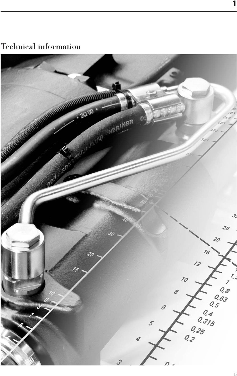
1 Technical information 5
2 1.1 Hose assemblies as elements in hydraulic systems Hose assemblies Hose assemblies have to perform crucial functions. Apart from transmitting power by means of liquid (hydraulic oil) they are frequently subjected to unwanted movements. When selecting a hose assembly the starting point is the highest pressure it will have to withstand. Although hydraulic systems are very likely to experience pressure surges caused for example merely by a gear change the pressure is often assumed to be no greater than that permitted after regulating the built-in pressure limiting value. In assuming this, it is often neglected that the response time of such components is relatively long compared with peak pressures that occur momentarily and often with greater frequency and whose multiplicity of causes, it may be assumed, are known. In cases of doubt, an oscillographical measurement is to be recommended that shows the frequency and amplitude of the actual pressure changes. Users/planners should in any case systematically investigate the specific application in advance and then select, install and maintain the hose type that will unconditionally meet the in-service requirements. The following 15 pages provide technical information such as determining the nominal diameter for a given throughput, dimensions of the hose and of the hose attachments, carrying capacity, chemical and thermal resistance, guidelines on the proper installation of hose assemblies and on determining the nominal length. All these items are crucial when selecting and installing a hose assembly. The following notes are guidelines, and no claim is made to completeness. We recommend the drawing up of performance specifications when the demands made on hose assemblies go beyond those described in pertinent recommendations. Hose assemblies, as referred to in safety regulations, are hoses that are connected with hose fittings, thereby forming a functioning unit. Hose assemblies must be put together in compliance with the ContiTech Techno- Chemie hose assembly manual. In particular, the following minimum requirements must be met: 1. Hose and couplings must be compatible and must function properly. 2. The max. shelf life for hoses and hose assemblies may not be exceeded. Regarding storage time, useful life and reuse of hose assemblies, please refer to DIN 7716 and Part In-service hose assemblies may not have any defects. NOTE: Incorrect selection, installation, use and maintenance may lead to a shorter useful life, bodily injury and/or property damage. When the right hose material is to be selected, ContiTech Techno-Chemie is pleased to assist and in complicated cases to work out an optimum solution, so that the above points can be avoided. Marking of hydraulic hose assemblies In accordance with DIN safety regulations, hydraulic hose assemblies must be marked clearly and permanently with the following data: 1. The manufacturer of the hose assembly 2. The date (i.e. month and year) of manufacture 3. The max. permissible dynamic working pressure (or another detail, such as the test pressure, as agreed with the customer). Example: TCH 05/91 PN 250 (test pressure 600 bar) 6

3 Technical information Elements of a hose assembly and definitions Letters used for measurements Hose Insert Shell Nut Hose part Connection part Hose coupling d 1 = Inner diameter of hose d 2 = Outer diameter of hose d 3 = Diameter of outer ply d 4 = Largest outer diameter of shell d 5 = Smallest inner diameter of insert d 6 = Inner diameter of coupling for tube connection d 7 = Diameter of connecting thread d 8 = Outer diameter of flanged head d 9 = Inner diameter of cross bore of the banjo I 1 = Hose assembly length from sealing surface to sealing surface I 4 = Fitting length to sealing surface I 5 = Exposed pipe length r min = smallest permissible bending radius on the inside s 1 = Hose wall thickness between inner and outer diameter s 2 = Hose wall thickness between inner diameter and diameter of outer ply s 3 = Hose wall thickness of the hose outer cover sw 1 = Width across flats of nut sw 2 = Width across flats of hexagonal bolt for securing 7

4 Nominal diameter DN The nominal diameter is a parameter used in hose assembly systems as a way of identifying matching parts, e.g. hoses and fittings. The nominal diameters are approximately equal to the inner diameters d 1 of the hoses, whereas the couplings for design reasons have smaller inner diameters. The nominal diameter has no unit and may not be used as a measurement, as defined in DIN 406. The following nomogram assists in determining the nominal diameter. Nomogram to determine the nominal diameter DN as a function of the volume flow and the flow rate Q (I/min) v (m/sec) DN A (cm 2 ) Application: The joining line between the two values Q (l/min) and v (m/sec) on the outer scales gives the nominal diameter at the point where it intersects the middle line. The resistance to flow has been neglected. Example: Given volume flow Q = 60 l/min Selected flow speed v = 5 m/sec Nominal diameter as determined = 16 8
 v (m/sec) DN A (cm 2 ) Application: The joining line between the two values Q (l/min) and v")
5 Technical information 1 Cross-reference of thread to nominal diameters DN DN Pipe Size Pipe- Metric ISO thread Thread acc. to. ISO diameter diameter LL+L S LL ** L S LL L S series series series series series series series series mm mm mm inch 2 4 M8x1 G 1/8 A* M10x1 M14x1,5 G 1/8 A* G 1/4 A* /16 M12x1,5 (M10x1) M12x1,5 M16x1,5 G 1/8 A* G 1/8 A* G 1/4 A* /4 M14x1,5 (M12x1) M14x1,5 M18x1,5 G 1/8 A* G 1/4 A* G 3/8 A* /16 M16x1,5 M16x1,5 M20x1,5 G 1/4 A* G 1/4 A* G 3/8 A* /8 M18x1,5 M18x1,5 M22x1,5 G 1/4 A* G 3/8 A* G 1/2 A* /2 M22x1,5 M22x1,5 M24x1,5 G 1/2 A* G 1/2 A* /8 M26x1,5 M26x1,5 M30x2 G 1/2 A* G 3/4 A* /4 M30x1,5 M30x2 M36x2 G 3/4 A* G 1 A* M38x1,5 M36x2 M42x2 G 1 A* G 1 1/4 A* /4 M45x1,5 M45x2 M52x2 G 1 1/4 A* G 1 1/2 A* /2 M52x1,5 M52x2 G 1 1/2 A* * for internal thread A does not apply ** The threads written in brackets apply to threaded pins acc. to DIN 3853 DN Pipe- Size Pipe- BSP NPTF/NPSM SAE J JIC 74 / SAE ORFS acc. to diameter diameter (BSPT / BSPP) 30 taper O-R SAE J 1453 LL+L S series series mm mm inch /8 1/8-28 1/8-27 5/ / /16 1/8-28 3/8-24 3/ /4 1/4-19 1/4-18 7/ / / /16 1/2-20 1/ /8 3/8-19 3/8-18 9/ / / /2 1/2-14 1/2-14 3/4-16 3/ / /8 5/8-14 7/8-14 7/ /4 3/4-14 3/ / / / /2 1 5/ / / /4 1 1/ /4-11 1/2 1 5/ / / /2 1 1/ /2-11 1/2 1 7/ / /2 2 1/ /2-12 Recommended tightening torques for nuts of hose assemblies Series Pipe- DN Thread Torque Ma in mkp for TCH fitting outerdiam. DKL 2) DKS 2) DKOL 3) DKOS 3) L 6 5 M12x1,5 1,0-1,2 -- 0,8-1, M14x1,5 1,2-1,5 -- 1,0-1, M16x1,5 2,0-2,5 -- 1,8-2, M18x1,5 3,0-3,5 -- 2,7-3, M22x1,5 5,0-5,5 -- 4,5-5, M26x1,5 7,5-8,5 -- 7,0-8, M30x M36x M45x M52x S 8 5 M16x1,5 -- 2,0-2,5 -- 1,8-2, M18x1,5 -- 3,0-3,5 -- 2,7-3, M20x1,5 -- 4,5-5, M22x1, M24x1, M30x M36x M42x M52x The adjacent values are reference values only and must be considered separately for each case; if necessary, the values must be checked. 2) DKL + DKS acc. to TCH ) DKOL + DKOS acc. to TCH Nuts acc. to DIN 3870 shape A Counter-fitting: Threaded pins acc. to DIN 3853 Bore type W DIN 3861 L+S series 9
 M12x1,5 M16x1,5 G 1/8 A* G 1/8 A* G 1/4 A* 6 8 10-4 1/4 M14x1,5 (M12x1) M14x1,5 M18x1,5 G 1/8 A* G 1/4 A* G 3/8 A* 8 10 12-5 5/16 M16x1,5 M16x1,5 M20x1,5 G 1/4 A* G 1/4 A* G 3/8 A* 10")
6 1.3 General guidelines for the installation of hose assemblies Certain regulations have to be complied with when installing hose assemblies to ensure and to maintain their functioning. Crucial elements are: ease of installation and removal, optimum installation routing and regular checking, so that any ensuing problems are minimised. The following instructions are based on DIN Part 4. Incorrect Correct Notes Fig. 1 Fig. 2 Compression Tensile stress Hose assemblies are to be installed in a way that excludes both tensile stressing (except by own weight) and compression. So they should be mounted with a sag that can take up any shortening of the hose. (See also the section Length changes and volume increases in hose assemblies ). Care must be taken not to twist the hose. Torsional stressing reduces the cross-section, thereby restricting the throughput and even damaging the plies (pressure bearers). The hose may not be twisted when the fittings are attached, either. Fig. 3 r min. Bending radii too small Abrasion 1,5 d ~ d r min. Hose assemblies may not be bent through an angle exceeding the permitted bending radius and certainly not buckled or kinked. This would cause a pressure build-up. Non-straight configurations are to be achieved by means of elbows and/or shaped hoes. The min. bending radii given in the manual refer to the rigid installation of hose assemblies. If the hose is required to move repeatedly in a tight bending radius (continuous operation), then the radius should be designed as large as possible. Any bending of a hose should not commence at a point less than 1.5 d from an end. Fig. 4 Bending radii too small Leave a sufficiently large gap Any deviation from the bending radii stipulated in the standard may well shorten the service life, depending on the stressing involved. r min. 10
 and compression.")
7 Technical information 1 Incorrect Correct Notes Fig. 5 Abrasion Leave a sufficiently gap Heat protection Although hoses enjoy a certain amount of resistance to abrasion, they are to be protected from external damage that could lead to excessive wear or the coupling being torn off the hose and hence to the premature failure of the hose material. Hose assemblies are to be protected from extreme temperatures that go beyond the limits for which the hose was designed. Special care is to be taken when hoses are installed close to hot power lines. In some applications it may be necessary to protect or to re-route the hose assembly. Information about protective hoses is available from ContiTech Techno-Chemie. It is obviously not possible to illustrate all forms of correct and incorrect installation. If very difficult installation condition prevail, a consultation with ContiTech Techno- Chemie is recommended. In the case of very unusual applications, it may be necessary to conduct trials before the hoses are selected. 11

8 1.4 Length changes and volume increases in hose assemblies The elasticity of hose material allows a hose to expand under pressure within certain limits. Under pressure, the yarn or steel-wire braid reinforcement depending on the type and angle of twist can withstand both longitudinal and radial expansion. The hose may experience a positive or negative change in length. The configuration in the installed state must allow for all possible changes in length so as to prevent the hose being ripped out of its coupling. The increase in volume that occurs helps to damp pressure peaks within certain limits. Information on the various hose types is available on request. Length changes under pressure for selected hose types in the most common nominal diameters A KRA 10 and KRA 20 OLN SOH 1TE and 2TE 3TE (up to DN 32) 3TB (from DN 40) 1SN and 2SN (up to DN 6) 1SN, 2SN, 1SC, 2 SC (from DN 8) 4SP and 4SH Change in length as a % Volume increases of hose assemblies (example: hose type 2 SN) Volume increase (cm 3 /m) DN 60 DN 50 DN 40 DN 32 DN 25 Nominal diameter Test pressure Volume increase bar cm 3 /m DN DN DN ,5 DN DN DN DN DN DN DN DN DN 20 DN DN 12 DN 10 DN 8 DN 6 Pressure (bar) 12

9 Technical information Important standards Account should be taken of relevant statutory industrial and manufacturing standards when hoses are selected. Hoses Standard Subject Corresponds to* Hose DIN EN 853 (issued 02.97) Hydraulic hoses with wire braid reinforcement SAE 100 R1 AT 1 SN SAE 100 R1 A 1 ST SAE 100 R2 AT 2 SN SAE 100 R2 A 2 ST DIN EN 854 (issued 02.97) Hydraulic hoses with textile ply SAE 100 R6 1 TE -- 2 TE SAE 100 R3 3 TE / 3TB DIN EN 855 (issued 02.97) Plastic hydraulic hoses with textile ply SAE 100 R7 PL 7 / ZL 7 SAE 100 R 8 PL 8 / ZL 8 DIN EN 856 (issued 02.97) Hydraulic hoses with wire spiral reinforcement -- 4 SP -- 4 SH SAE 100 R12 -- SAE 100 R13 -- DIN EN 857 (issued 02.97) Compact hydraulic hoses with wire -- 1 SC spiral reinforcement -- 2 SC * SAE standards only contain some of the requirements stipulated in DIN Terms Standard Subject DIN (issued 09.85) Pressure: Values and terms DIN (issued 07.78) Hose assemblies: terms DIN (issued 07.78) Hose assemblies: Letters used for measurements DIN (issued 11.80) Rubber and elastomers: terms Hose assemblies Standard Subject DIN (issued 02.82) Hose assemblies: measurements, requirements DIN (issued 05.84) Hose assemblies: installation DIN (issued 06.93E) Hose assemblies: rating of reliability Hose fittings Standard Subject DIN (issued 02.82) Hose fittings: requirements, installation instructions, testing Testing Standard DIN EN ISO 6803 (issued 07.97) (Replacement for DIN 20024) Subject Rubber and plastic hoses and hose assemblies: hydraulic pressure impulse testing without bending 13
 Hydraulic hoses with textile ply SAE 100 R6 1 TE -- 2 TE SAE 100 R3 3 TE / 3TB DIN EN 855 (issued 02.")
10 1.6 Selection of the right type of hose using the nominal diameter and pressure ratings DN Type Spec. No A AH GCN GCNA GCW GCWA GCDR/GCDRW 2286/ GCADR/GCADRW 2287/ OLN OLNW OLNS OLNH(W) 2265/ KRAV KRA ) SOH ) ) DBSLK 2503/ TE TE TE/3 TB 2336/ SN SC SN SC SC-HP SN-HP SP SH (4 SPS) ) HPO b-mini ) HPC SK SR PL7/ZL7* 2465/ PL8/ZL8* 2466/ TFS TWS PTFEW * on request also available as twin hose 1) = DN 46 / DN 50 2) = inside = 2.5 mm 3) = with special approval for 430 bar 4) = DN 85 5) = DN 15 Approval from German Lloyd with additional flame protection Approval from German Lloyd without additional flame protection 14
 2265/2279 30 30 30 27 27 25 20 20 20 20 KRAV 10 2102 10 KRA 20 2264 25 25 10 10 15 15 10 5) SOH 2367 25 25 25 20 20 20 1) 20 15 4) DBSLK 2503/2508 10 10 10 10 10 1 TE 2315 25")
11 Technical information Selection of hose assemblies via the type of connection Ferrule/shell Part No. 1 TE ** 2 TE ** 3 TE/3 TB 1 SN 1 SC 2 SN 2 SC 1 SC-HP 2 SN-HP 4 SP 4 SH / are only supplied ML ML/TL TL 6 as one-piece ML ML/TL TL TL TL TL TL TP 8 couplings ML ML/TL TL TL TL TL TL TL 10 ML ML/TL TL TL TL TL TL TL TP 12 ML ML/TL TL TL TL TL TL TL TP 16 ML ML/TL TL TL TL TL TL TL TLP 20 ML ML/TL TL TL TL TL TL WL WL 25 ML ML/TL TL TL TL TL WL 32 TL TL TL WL 40 TL TL TL 50 TL ES* ES* 60 UPR 70 UPR 80 NS* 100 NS* Ferrule/shell Part No. HPO b-mini HPC 2 SK PL7/ZL7*** PL8/ZL8*** SR 1 TFS* TWS* PTFEW* / / are only supplied * (DN 2,5) * (DN 4) * 6 as one-piece * TL TL TL TL 8 couplings TL TL TL TL 10 TL TL TL TL 12 TL TL TL 16 TL TL 20 TL 25 TL * fittings on request ** insert ML crimped *** on request also as twin hose available 15

12 1.7.2 Selection of hose assemblies via the type of connection Type Ferrule/shell Inner diam. Part No. A AH GCN GCNA GCW GCWA GCDR/GCDRW / , , , , , , , , , are only supplied 32 as one-piece TL TL TL 40 couplings TL TL TL 50 TL TL TL UPR UPR * fittings on request ** insert ML crimped *** (DN 40/46) 16

13 Technical information 1 GCADR/GCADRW OLN OLNW OLNS1 OLNH(W) KRAV 10 KRA 20 SOH DBSLK 1 TE ** 2 TE ** 3 TE/3 TB** 2287/ / / /2326 * (DN14) TL TL TL TL TL TL TL TL TL *** TL TL ES* UPR UPR NS* UPR NS* 17
 TL TL TL TL TL TL TL TL TL *** TL TL ES* UPR UPR NS* UPR")
14 1.8 Notes on ordering To ensure the prompt and trouble-free handling of your order, would you please observe the following procedure: A) Ordering individual parts For individual parts such as hoses, shells, inserts, nuts and accessories, just give the part nos. from the corresponding tables. Example 1: Hose: OLN; type no. 2255; DN 12 Part no.: Shell : DN 12 for OLN Part no.: (ID 23 mm) Insert: Coupling DKL; DN 12; Part no.: Spec. no. 290 Nut: M 22x1,5 Part no.: Adapter: M 22x1,5 Part no.: Example 2: Hose: OLN; type no. 2255; DN 32 Part no.: One-piece Coupling: Coupling DKLL; Spec. no. 300: DN; 32 TL Part no.: B) Ordering hose assemblies The part numbers of complete ContiTech Techno-Chemie hose assemblies consist of 5 blocks of digits. The meaning of the constituent blocks is illustrated by the adjacent example. It refers to an OLN hose of nominal diameter of 12, a CEL coupling at one end and a DKL coupling at the other. The hose assembly is 800 mm long Length of hose assembly 800 mm Coupling DKL, spec. no. 290 Coupling CEL, spec. no. 200 Nominal diameter 13 Hose type OLN OLN Low pressure hose 18

15 Technical information 1 Points to remember when ordering: 1. For hose assemblies with TL, ML and WL couplings, the first digit of the hose type no. changes from 2 to B; e.g. from to B The nominal diameter of the hose should always be given as two digits in the part no. Please write: 02 for DN 2 08 for DN 8 04 for DN 4 13 for DN for DN 6 91 for DN The types of coupling are defined by abbreviations and specification numbers. Examples: Abbrev. Spec. no. BEL 100 CEL 200 DKL 290 Further abbreviations and spec. nos. are given in the coupling tables. 4. A hose assembly with only one coupling is given the specification number 000 for the end without a coupling. 5. Determining the nominal length of hose assemblies. Some examples for showing the lengths of hoses and hose assemblies are given here. 6. Recommended standard lengths I 1 und I 2 of hose assemblies

16 Points to remember when ordering: 7. Permissible deviations from measurements I 1 und I 2 for installed hose assemblies. The manufacturing tolerances comply with DIN Length l 1 and l 2 Tolerance from DN 32 from DN 60 up to DN 25 up to DN 50 up to DN 100 up to from 630 to from 1250 to from 2500 to ,5 % - 0,5 % over % - 1 % 8. Positioning of elbows on hose assemblies - If no details are given to the contrary, the elbows are fitted in such a way that they both point in the same direction. - If the elbows are to be turned round, the angle concerned must be stated. It is always given in a counter-clockwise direction. - The elbow with the smaller bending angle always points down. Couplings illustrated turned in plane of projection 20

17 Technical information 1 Illustrations The various ContiTech Techno-Chemie hose couplings are referred to throughout the brochure (in both text and illustrations) by their abbreviation and in some cases illustrated uncrimped (for self-mounting presses). -ML The crimped version of the following types is illustrated for ease of understanding: TL TP/TLP (DN 6-16) WL (DN 20-32) After selection of hoses and connections, and with the help of our crimping data sheets on positioning the fittings, it is easy to complete hose assemblies using suitable crimpers. 21

800-348-8467 www.fittingsunlimited.com
 Thread and Port Identification Guide 800-348-8467 www.fittingsunlimited.com INDEX Index... 1 Explanation of Symbols... 2 How to Measure Threads... 3-4 Metric vs English Threads... 5 North American Connections
Hose and Tube Fittings Series 1-3
 Embracing Challenge Hose and Tube Fittings Series 1-3 out of plastics PP, PVDF, PTFE Series 1 Special Features Corrosion resistant Gas tight Easy to handle Different connection threads Application Hose
Thread and End Connection
 www.swagelok.com and End Connection Identification Guide 2 Contents Introduction and End Connection Terminology.. 4 General Terminology... 5 Step-by-Step Identification Procedure for s and End Connections...
Working Pressure - Hose Ends
 Working Pressure - Hose Ends The maximum dynamic working pressure of a hose assembly is the lesser of the rated working pressure of the hose and the end connection used. HIGH SPECIALTY HOSE ACCESSORRIES
VdS 2100-09en. VdS Guidelines for water extinguishing systems. Non-return valves. Requirements and test methods. VdS 2100-09en : 2011-05 (01)
") VdS Guidelines for water extinguishing systems VdS 2100-09en Requirements and test methods VdS 2100-09en : 2011-05 (01) Publishing house: VdS Schadenverhütung GmbH Amsterdamer Str. 172-174 50735 Köln,
VdS Guidelines for water extinguishing systems VdS 2100-09en Requirements and test methods VdS 2100-09en : 2011-05 (01) Publishing house: VdS Schadenverhütung GmbH Amsterdamer Str. 172-174 50735 Köln,
NEW SIX-SEALS CUTTING RING. INTERNATIONAL INDUSTRIAL PATENT Nr. 864061 of the 10/03/99 FLANKS AND DOES NOT REPLACE THE STANDARD RING CURRENTLY IN USE
 B4 NEW SIX-SEALS CUTTING RING. INTERNATIONAL INDUSTRIAL PATENT Nr. 864061 of the 10/03/99 FLANKS AND DOES NOT REPLACE THE STANDARD RING CURRENTLY IN USE AVAILABLE IN CARBON AND STAINLESS STEEL 23 THEORY
ASSEMBLY INSTRUCTIONS ACCORDING TO SAE J1453 FOR FLARED TUBES. 5. Clean properly with appropriate products the part of the tube to be flared.
 ASSEMBLY INSTRUCTIONS ACCORDING TO SAE J1453 FOR FLARED TUBES 1. Before to start to flare the tube check for the correct parameters of all the tools to be used and substitute 2. Cut the tube at a 90 angle
SERIES ASM NEOPRENE/EPMD FLANGED SINGLE SPHERE CONNECTOR CONNECTORS. Pressures to 225 PSIG (15.51 barg) Temperatures to 230ºF (110ºC)
 Temperatures to 230ºF (110ºC)") APPLICATIONS Process Industry Weak Acids Alkalies Compressed Air Pulp & Paper MODELS ASM - Flanged Connection OPTIONS Control Rods Oil & Gas Water & Waste Pump suction & discharge Sea water Chemical lines
APPLICATIONS Process Industry Weak Acids Alkalies Compressed Air Pulp & Paper MODELS ASM - Flanged Connection OPTIONS Control Rods Oil & Gas Water & Waste Pump suction & discharge Sea water Chemical lines
HYDRAULIC PIPING STANDARD HANDBOOK. Revision 1
 HYDRAULIC PIPING STANDARD HANDBOOK Revision 1 Preface We aim to fill a gap in technical literature. At this moment there are no hydraulic piping standards available which cover different pressure classes
FAG Hydraulic nuts. Technical Product Information
 FAG Hydraulic nuts Technical Product Information Contents Application 2 Design 2 Design variants 3 Pressure generators, connectors 4 Dimension tables for FAG hydraulic nuts (metric) 6 Dimension tables
Highly flexible couplings
 Construction and operation 8.03.00 Instructions for installation 8.03.00 Types of stress 8.04.00 Diagrams for static deformation of the coupling ring 8.05.00 Coupling size 8.07.00 Examples of combinations
Pipe Thread Types and Designations
 Pipe Thread Types and Designations Overview: Different types of screw threads have evolved for fastening, and hydraulic systems. Of special concern are plastic-to-metal, taper/parallel threaded joints
Application Data Important Safety Information
 Application Data Important Safety Information Read this page before using any of the information in this catalog. This catalog is designed to be used as a guide in selecting the proper hose for the applications
BROEN UNiFlEx FiTTiNgs FOR BURNiNg gases OEN OEN ifl ifl FOR FOR BURN BURN gas gas
 BROEN UNIFLEX Fittings FOR BURNIN ASES BROEN UniFlex TM Fittings for burning gases BROEN UniFlex TM Fittings for burning gases LAB Table of Contents Content Page Table of Content 2 Product Overview 3 BROEN
Machine devices, jig devices
 Machine devices, jig devices 853 K0697 Rolled thread studs DIN 6379 Material: Tempered steel. KIPP Rolled thread studs DIN 6379 Order No. D L B1 B2 Approx. weight g Surface finish: Thread rolled. Class
Green Thread Product Data
 Green Thread Product Data Applications Dilute Acids Caustics Produced Water Industrial Waste Hot Water Condensate Return Materials and Construction All pipe manufactured by filament winding process using
SIGRAFLEX EMAIL. Properties. Applications
 Multilayer sealing sheet, adhesive-free made from flexible graphite foil reinforced with stainless steel foils especially for use in PTFE envelope gaskets SIGRAFLEX EMAIL has been developed specially for
Failure to comply with the following cautions and warnings could cause equipment damage and personal injury.
 1.0 IMPORTANT RECEIVING INSTRUCTIONS Visually inspect all components for shipping damage. Shipping Damage is not covered by warranty. If shipping damage is found, notify carrier at once. The carrier is
Removing chips is a method for producing plastic threads of small diameters and high batches, which cause frequent failures of thread punches.
 Plastic Threads Technical University of Gabrovo Yordanka Atanasova Threads in plastic products can be produced in three ways: a) by direct moulding with thread punch or die; b) by placing a threaded metal
The number of parameters required for authoring an ipart depends on the type of the part you are publishing.
 Publishing and Styles In This Exercise This Skill Builder demonstrates how to create a tube and pipe ipart, publish it into a custom Tube & Pipe Library, create a style using published parts, and then
Working Pressure up to 630 bar / 9135 PSI
 Test Hoses SMS / SS + Working Pressure up to 630 bar / 9135 PSI Technical Data for Test Hose A B C D Nominal Bore () (mm) Max. Working Pressure (PN) (bar / PSI) 00 / 5801 630 / 9135 30 / 931 630 / 9135
Cables. Accessories. For Force, Torque and Strain Sensors
 Accessories Cables For Force, Torque and Strain Sensors Charge mode, high impedance piezoelectric measurement demands highly insulated coaxial cables and connectors to ensure an insulation resistance greater
PPS-PPQ-BT-PIAS RESIN INSULATORS FOR OIL INSULATED ELECTRICAL MACHINES
 PPS-PPQ-BT-PIAS RESIN INSULATORS FOR OIL INSULATED ELECTRICAL MACHINES BUSHING WITH PLUG CONNECTION WITH OUTER CONE PPS CHARACTERISTICS The PPS bushing can be used as a fixed section for the entry of medium
DiwiTherm, Resistance Thermometers Model TR75, with digital Display Battery or Solar Powered
 Electrical Temperature Measurement DiwiTherm, Resistance Thermometers Model TR75, with digital Display Battery or Solar Powered WIKA Data Sheet TE 60.75 Applications Machinery, plant and tank construction
Ecoflex Wall Penetration Systems: An efficient, sustainable solution for penetrating concrete or block walls
 Pre- insulated pipe systems ecoflex Wall Penetration installation guide Ecoflex Wall Penetration Systems: An efficient, sustainable solution for penetrating concrete or block walls Pre-insulated Pipe Systems
Two most common lock nut groups: 1-Prevailing Torque Type Lock Nuts:
 Two most common lock nut groups: 1. PREVAILING TORQUE a design feature of the lock nut produces friction between threads of mated components thereby increasing the force needed to tighten as well as loosen
The KLINGERexpert 5.2.1
 KLINGERexpert 5.2.1 Powerful Sealing Calculation The KLINGERexpert 5.2.1 gasket design program is a versatile piece of software to assist users in the selection of non-metallic gasket materials. KLINGER
AISI CHEMICAL COMPOSITION LIMITS: Nonresulphurized Carbon Steels
 AISI CHEMICAL COMPOSITION LIMITS: Nonresulphurized Carbon Steels AISI No. 1008 1010 1012 1015 1016 1017 1018 1019 1020 1021 1022 1023 1024 10 1026 1027 1029 10 1035 1036 1037 1038 1039 10 1041 1042 1043
TITAN Fuel Tanks. INSTALLATION INSTRUCTIONS G e n e r a t i o n V
 TITAN pt. no.: 02 0000 0143 Important: Please read these instructions carefully and completely before starting the installation. TITAN Fuel Tanks INSTALLATION INSTRUCTIONS G e n e r a t i o n V Extended
R310EN 2225 (2011.04) The Drive & Control Company
 The Drive & Control Company") Ball Rail Systems Resist NRII R310EN 5 (011.04) he Drive & Control Company R310EN 5 (011.04) Ball Rail Systems Resist NR II Bosch Rexroth AG 3 Ball Rail Systems Resist NRII General Product Description
Ball Rail Systems Resist NRII R310EN 5 (011.04) he Drive & Control Company R310EN 5 (011.04) Ball Rail Systems Resist NR II Bosch Rexroth AG 3 Ball Rail Systems Resist NRII General Product Description
THERMA-TUBE preinsulated pipes and fittings Catalogue of products
 THERMA-TUBE preinsulated pipes and fittings Catalogue of products THERMA TUBE preinsulated pipes and fittings TABLE OF CONTENTS 1. GENERAL INFORMATION ABOUT THE USE OF PREINSULATED PIPES AND FITTINGS...
HOSE, TUBE, AND PIPE CLAMPS
 hose, tube & clamp B/W pages 24/6/08 9:28 AM Page 2 HOSE, TUBE, AND PIPE CLAMPS TABLE OF CONTENTS Introduction 3 Construction 3 Application 3 Mounting 3 Standard Duty Clamps (HRL) Arrangements 4 Dimensions
B 246 Assembly instructions
 B 246 Assembly instructions VOSS quick connect system 246 for diesel fuel systems in automotive engineering These assembly instructions are intended for qualified fitters of fuel systems in automotive
Product catalogue, tank cleaning systems
 Product catalogue, tank cleaning systems Aquamat Tank cleaning units Aquarex Tank cleaning systems www.hammelmann.com Contents (Navigation via Bookmarks) Tank cleaning units L XL XXL High pressure lance
Screw Thread Design. Rev. 3-4-09
 Screw Thread Design Screw Thread Fundamentals A screw thread is defined as a ridge of uniform section in the form of a helix on either the external or internal surface of a cylinder. Internal threads refer
White paper. SACE Tmax XT Circuit-Breaker Terminals and Connection
 White paper SACE Tmax XT Circuit-Breaker Terminals and Connection Circuit-Breaker Terminals and Connections Index Introduction... 2 1. Components used for wiring... 3 1.1. Electrical...3 1.2. Flexibility
due to uncertainty. This, in turn, has a direct impact on equipment availability and maintenance costs. Unfortunately, due to misconceptions and
 due to uncertainty. This, in turn, has a direct impact on equipment availability and maintenance costs. Unfortunately, due to misconceptions and pressure from plant operators to get "back on line", it
Pipe threads for tubes and fittings where pressure-tight joints are not made on the threads. (requires PTFE sealing tape or liquid sealant).
.") Fittings for CO 2 Pipe Threads Pipe thread references quoted in this catalogue conform with the requirements specified in the latest issue and amendments of the following ISO Standards: ISO 7-1 (BS21)
Fittings for CO 2 Pipe Threads Pipe thread references quoted in this catalogue conform with the requirements specified in the latest issue and amendments of the following ISO Standards: ISO 7-1 (BS21)
Introduction to vacuum gauges. Vacuum Gauges where the Pressure Readings are Independent of the Type of Gas (Mechanical Vacuum Gauges)
") Introduction to vacuum gauges Vacuum Gauges where the Pressure Readings are Independent of the Type of Gas (Mechanical Vacuum Gauges) BOURDON Vacuum Gauge The inside of a tube which is bent into a circular
Introduction to vacuum gauges Vacuum Gauges where the Pressure Readings are Independent of the Type of Gas (Mechanical Vacuum Gauges) BOURDON Vacuum Gauge The inside of a tube which is bent into a circular
James M. Pleasants Company
 James M. Pleasants Company SUBMITTAL DATA GAINESVILLE MECHANICAL DECEMBER 20, 2013 PROJECT: GSU: J-183 HUMANITIES LAW BLDG. QUOTE NO:12116 ENGINEER: STEVENS & WILKINSON GASKETED PLATE HEAT EXCHANGER Tag:
Series 510 Submersible Level Transmitters
 Series 510 Submersible Level Transmitters The Series 510 Submersible Level Transmitters are solid state instruments designed for direct submergence into many types of liquid for quick, accurate and reliable
Loewe GK Installation and operating manual
 SCHMIDT-KUPPLUNG GmbH Loewe GK Installation and operating manual Loewe GK Loewe GK: angular and radial displacement compensation combined with axial stiffness. The compact coupling combines angular and
Technical Data. 7. Bearing Fits. 7.1 Interference. 7.2 Calculation of interference F B LLLLLLLLL( A-54
 Technical Data 7. Bearing Fits 7.1 Interference For rolling s the rings are fixed on the or in the housing so that slip or movement does not occur between the mated surface during operation or under. This
SISTO-16TWA/HWA/DLU. Type Series Booklet
 Diaphragm Valve SISTO-16TWA/HWA/DLU PN16 DN 15-200 Maintenance-free Flanged Ends Type Series Booklet Legal information/copyright Type Series Booklet SISTO-16TWA/HWA/DLU All rights reserved. The contents
Mounting instructions for SOT78 (TO-220AB); SOT186A (TO-220F)
; SOT186A (TO-220F)") Mounting instructions for SOT78 (TO-220AB); SOT186A (TO-220F) Rev. 1 29 May 2012 Application note Document information Info Keywords Abstract Content SOT78; SOT186A; TO-220AB; TO-220F This application
Mounting instructions for SOT78 (TO-220AB); SOT186A (TO-220F) Rev. 1 29 May 2012 Application note Document information Info Keywords Abstract Content SOT78; SOT186A; TO-220AB; TO-220F This application
Spiroflex spiral-wound gaskets
 Spiral-wound gaskets have long been used as sealing elements in refineries, chemical plants, gas installations, water treatment plants and in general pipeline construction. Spiroflex gaskets SpV retain
2013 Edition. Flanged fittings 30"-64" NSF. industrial Applications, water & Wastewater. Certified to ANSI/NSF 61
 30"-64" Ductile Iron industrial Applications, water & Wastewater 2 Table of Contents Flanged Fittings for Water 3 Flange Details 5 Flanged Fittings 6 90º and 45º Bend 6 22-1/2º and 11-1/4º Bends 7 Tees
ZF 301 A. Marine Propulsion Systems
 Marine Propulsion Systems 10 Down angle, direct mount marine transmission. Description Robust design also withstands continuous duty in workboat applications. Fully works tested, reliable and simple to
Structural Bolting. Notice the Grade 5 has a much smaller head configuration and a shorter shank then the A325 structural bolt. Rev.
 Structural Bolting ASTM A325 and ASTM A490 are the two U.S. standard structural bolts. When looking at the mechanical requirements of bolts it appears that an ASTM A325 and SAE J429 Grade 5 are identical
7.3 Fit selection. Inner ring: Rotating. Outer ring: Stationary. Inner ring: Stationary. Outer ring: Rotating. Inner ring: Stationary
 7. Bearing Fits 7. Fitting For rolling s, inner and outer rings are fixed on the or in the housing so that relative movement does not occur between fitting surfaces during operation or under. This relative
Shaft- Mounted Speed Reducers
 Torque Arm Design Considerations for Todd R. Bobak has worked in the gear industry for 15 years. He has held positions in technical service, design and development, and quality assurance. He is a product
Specification for Rotary Drill Stem Elements
 Addendum 1 March 2007 Effective Date: September 1, 2007 Specification for Rotary Drill Stem Elements ANSI/API SPECIFICATION 7-1 FIRST EDITION, MARCH 2006 EFFECTIVE DATE: SEPTEMBER 2006 ISO 10424-1:2004
high-pressure Hydraulics 70-300 MPa High-Pressure Hydraulics Combining top class technology, safety focus and responsiveness to stay one step ahead
 high-pressure Hydraulics 70-300 MPa High-Pressure Hydraulics Combining top class technology, safety focus and responsiveness to stay one step ahead 2 Content Content Content Market Leadership Is More Than
One and Two-piece Torque Rods and Replacement Bushings LIT NO: 45745-148
 One and Two-piece Torque Rods and Replacement Bushings LIT NO: 45745-148 DATE: January 2008 REVISION: B HENDRICKSON ULTRA ROD PLUS Torque Rod Bonded Bushing Provides Longer Life Bonding makes a better
Product catalogue, pipe and sewer cleaning systems
 Product catalogue, pipe and sewer cleaning systems Nozzles Rotorjet trolley Hose reels Cleaning devices www.hammelmann.com Contents (Navigation via Bookmarks) Rotorjet trolley Rotary joints, spray pipes
Tubing and Accessories
 Section 7 Tubing and Accessories Inch Industrial Tubing................................FIT-7-2 Metric Industrial Tubing...............................FIT-7-3 Inch D.O.T. Tubing...................................FIT-7-3
Machine needle shut-off nozzle type-a
 Machine needle shut-off nozzle type-a spring operated Applications: Thermoplastics (not applicable for PVC) Shut-off mechanism: Operated with one axial high performance spring Index of contents Chapter
60.12. Depend-O-Lok FxE Expansion Coupling. System No. Submitted By Spec Sect Para Location Date Approved Date. DEPEND-O-LOK FxE EXPANSION COUPLING
 60.1 D-O-L FxE expansion couplings are a bolted, split-sleeve design that provides for expansion and contraction at the coupled joint. These couplings are furnished with restraint rings that, when affixed
GK Packing System Welding Instructions
 GK Packing System Welding Instructions Roxtec GmbH Neuer Höltigbaum 1-3, 22143 Hamburg GERMANY Tel +49 (040) 657398-0, Fax +49 (040) 657398-50 EMAIL info@de.roxtec.com, www.roxtec.de Welding instructions
Machine nozzle with needle shut-off type HP pneumatically or hydraulically controlled
 Machine nozzle with needle shut-off type HP pneumatically or hydraulically controlled Applications: Thermoplastics (not applicable for PVC) Shut-off mechanism: Needle shut-off with integrated 2-way actuator
Puddle Flange. FRANK Puddle Flange
 Puddle Flange FRANK Puddle Flange The problem Problems keep on occurring when connecting pipes during construction work. Pipes laid in the ground must be introduced into concrete walls or shafts. In many
Art.S001-S002 SOLAR MODULE WITH DELIVERY AND RETURN CONNECTIONS
 Art.S001-S002 SOLAR MODULE WITH DELIVERY AND RETURN CONNECTIONS Technical Information sheet 0001/07/Rev01 ENG FUNCTION Series S001 and S002 circulation units are applied to the primary circuit of solar
Reaction Torque Sensor
 Force 1 1 N m up to 1 000 1 000 N m Type 9329A 9389A These easy to install piezoelectric reaction torque sensors are particularly suitable for measuring rapidly changing torques at non-rotating shafts.
Butt Fusion Welding of HDPE Pipes Work Procedure
 Butt Fusion Welding of HDPE Pipes Work Procedure A pipeline is as good as its weakest point. Accordingly it is not only important that quality pipes and components are used in a piping system, but also
For New Technology Network. Steel Manufacturing Machinery Product Guide Book
 For New Technology Network R Steel Manufacturing Machinery Product Guide Book Ecological / Economical proposals from NTN NTN products exhibit benefits at various locations. Steel manufacturing equipment
Figure 2 The fan and shroud also needs to be removed for access to the four a/c compressor bolts and removal of the compressor from the top.
 Here are some pictures to show what s required when replacing the A/C compressor, expansion valve and receiver/drier on a 2001 Volvo V70. Even if you don t replace these A/C parts these pictures can help
ISORIA. Centered disc butterfly valves with AMRING elastomer liner. 240 PSI: 1½ to8. 150 PSI : 10 to 24
 Type series booklet 8448.1/2-EN--US ISORIA Centered disc butterfly valves with AMRING elastomer liner 240 PSI: 1½ to8 150 PSI : 10 to 24 Design in accordance with ISO 10631 Manual, electrical, pneumatical
Hydraulic Control Solutions
 Hydraulic Control Solutions Vexve s Hydrox hydraulic control solutions are suitable for even the most challenging installation sites and conditions. Specifically designed for district heating and district
kymanual or Automatic - it s your Choice
 . kymanual or Automatic - it s your Choice ky LKB Automatic or Manual Butterfly Valve Application LKB is a sanitary automatically or manually operated butterfly valve for use in stainless steel pipe systems.
Self-operated Temperature Regulators Temperature Regulator Type 1u
 Self-operated Temperature Regulators Temperature Regulator Type u Application Temperature regulators for cooling installations Control thermostats for set points ) from 0 to 250 C G ½ to G or DN 5 to 50
Plastics for Longer Life. The NEW Multi-Axis Energy Chain for Robots. Triflex
 The NEW Multi-Axis Energy Chain for Robots Triflex R Triflex R Features Modular energy supply for longer cable life on robots if-design 2004 3-D E-Chain for robotic applications This long-life, modular
Dampers. Inlet guide vane. Damper. Louvre damper. Handbook Radial Fans / Chapter 3 - Dampers REITZ List 2010 DO 1. Dampers
 Inlet guide vane Damper ouvre damper Handbook Radial Fans / Chapter 3 - REITZ ist 2010 DO 1 Technical description rticle number and order code article number = component size DR D1 0 3-000 031-00 variant
DET NORSKE VERITAS TYPE APPROVAL CERTIFICATE
 Pagina 1 di 6 DET NORSKE VERITAS TYPE APPROVAL CERTIFICATE CERTIFICATE NO. P-12685 This Certificate consists of 6 pages This is to certify that the Flexible Hoses of Non-Metallic Material with Permanently
ZF W320 Vertical offset, direct mount marine transmission.
 Marine Propulsion Systems Vertical offset, direct mount marine transmission. Maximum Input** Duty kw hp RPM Medium 425 570 2400 Continuous 357 479 2400 ** Must not be exceeded Description Robust design
ZF 220 A 10 Down angle, direct mount marine transmission.
 Marine Propulsion Systems 10 Down angle, direct mount marine transmission. Maximum Input** Duty kw hp RPM Pleasure 419 562 4500 Light 394 528 4500 Medium 335 449 4500 Continuous 192 258 3200 ** Must not
Fluid Level Gauge Fluid Level Sensor Temperature Switch FSA / FSK / TS
 Fluid Level Gauge Fluid Level Sensor Temperature Switch FSA / FSK / TS up to size 381; to PN 0.5; to T = 80 C 1. Description 1.1. General FSA fluid level gauges, FSK fluid level sensors and TS temperature
ATS Overhead Table Shelf System INSTRUCTION MANUAL
 ATS Overhead Table Shelf System INSTRUCTION MANUAL ATS Overhead Table Shelf System Instruction Manual Warranty Newport Corporation warrants this product to be free of defects in material and workmanship
Geometry and dimensional tolerances of engine bearings
 Geometry and dimensional tolerances of engine bearings Dr. Dmitri Kopeliovich (Research & Development Manager.) 1. Hydrodynamic lubrication Engine bearings operate mostly in the hydrodynamic regime of
GPD Rubber Press Seals
 GPD Rubber Press Seals Leading in in ideas SYSTEM-TECHNIK GPD Rubber Press Seals Design Available with a rubber thickness of 30 mm for sealing against non-pressing water and a rubber thickness of 60 mm
ENGINEERING COMMITTEE
 ENGINEERING COMMITTEE Interface Practices Subcommittee AMERICAN NATIONAL STANDARD ANSI/SCTE 02 2006 Specification for F Port, Female, Indoor NOTICE The Society of Cable Telecommunications Engineers (SCTE)
Unique DV-ST UltraPure - Manuel: for valve sizes DN8 to DN80 (¼ to 3 )
") Instruction Manual Unique DV-ST UltraPure - Manuel: for valve sizes DN8 to DN80 (¼ to 3 ) ESE01752-EN4 2014-02 Original manual Table of contents The information herein is correct at the time of issue
Instruction Manual Unique DV-ST UltraPure - Manuel: for valve sizes DN8 to DN80 (¼ to 3 ) ESE01752-EN4 2014-02 Original manual Table of contents The information herein is correct at the time of issue
Lenntech. 1000 psi End port pressure vessels 2.5. User s Guide to: Phoenix Vessel Technology Limited. Model number: 1503
 1 User s Guide to: Phoenix Vessel Technology Limited 1000 psi End port pressure vessels 2.5. Model number: 1503 Lenntech info@lenntech.com Tel. +31-152-610-900 www.lenntech.com Fax. +31-152-616-289 Phoenix
Self-aligning ball bearings
 Self-aligning ball bearings Designs... 470 Basic design... 470 Sealed bearings... 470 Bearings with an extended inner ring... 472 Bearings on sleeves... 473 Self-aligning ball bearing kits... 474 Appropriate
3/2- and 2/2-way cartridge valve type BVE
 3/2- and 2/2-way cartridge valve type BVE for any flow direction, zero leakage, all ports pressure resistant Flow Q max = 70 lpm Perm. pressure p max = 400 bar Additional valves with same function: ' Type
ZF W325 Vertical offset, direct mount marine transmission.
 Marine Propulsion Systems Vertical offset, direct mount marine transmission. Maximum Input** Duty kw hp RPM Medium 507 680 2600 Continuous 430 577 2600 ** Must not be exceeded Description Robust design
LEGACY REPORT ER-5110. www.icc-es.org. ICC Evaluation Service, Inc. Reissued November 1, 2003. Legacy report on the 1997 Uniform Building Code
 LEGACY REPORT Reissued November 1, 2003 ICC Evaluation Service, Inc. www.icc-es.org Business/Regional Office # 5360 Workman Mill Road, Whittier, California 90601 # (562) 699-0543 Regional Office # 900
Assembly instructions VOSS quick connect system 246 NX
 Assembly instructions VOSS quick connect system 246 NX Convenient connection, positioning and release A. Important notices Please observe before using the quick connect system VOSS quick connect system
POSEIDON 2-29, 2-25 & 2-22 POSEIDON 2-29, 2-25 & 2-22 XT
 POSEION 2-29, 2-25 & 2-22 POSEION 2-29, 2-25 & 2-22 XT Repair Manual Index A. Safety precautions 3 B. Technical data 4 C. Structure 5-6. Service / Repair 7-23 E. Tools 24 F. Function 25-26 G. Electric
Mikrotherm. Manual radiator valves. To be precise.
 Manual radiator valves To be precise. Description HEIMEIER Mikrotherm manual radiator valves made of corrosion-resistant gunmetal, with white plastic hand wheel cap, tight-packed with protection film.
Machine needle shut-off nozzle type HP
 Machine needle shut-off nozzle type HP pneumatically or hydraulically controlled Index of contents Chapter Page Safety instructions... 2 Installation instructions... 3 - Installation steps... 3 Initial
EEC 94/20/EC APPROVED KINGPINS
 EEC 94/20/EC APPROVED KINGPINS All Capus EEC approved Kingpin Assemblies have been tested in Germany by RWTuV. The tests include a simulated life test - 2 million cycles at the approved 'D' value loadings.
Important: Please read these instructions carefully and completely before starting the installation. TITAN Fuel Tanks
 TITAN pt. no.: 03 0000 0120 Important: Please read these instructions carefully and completely before starting the installation. TITAN Fuel Tanks INSTALLATION INSTRUCTIONS G e n e r a t i o n V Extended
Robot Welding Torch System
 T e C H N O L O G y f O R T H e W e L d e R s W O R L d. Robot Welding Torch System W W Robot welding torch system... The universal MIG/MAG-torch system for robot welding: A new interface and cable assembly
ASTM D 1599 Standard Test Method for Resistance to Short-Time Hydraulic Pressure of Plastic Pipe, Tubing, and Fittings
 ASTM D 1599 Standard Test Method for Resistance to Short-Time Hydraulic Pressure of Plastic Pipe, Tubing, and Fittings This test method establishes the short-time hydraulic failure pressure of pipe and
Drill String Design. The following topics will be discussed
 Drill String Design The following topics will be discussed Kelly Drill pipe Drill collars Accessories; heavy wall drill pipe, jars, stabilizers, reamers, shock sub and bit sub Drill bits 1 Kelly Used to
ZF 286 A 7 Down angle, direct mount marine transmission.
 Marine Propulsion Systems 7 Down angle, direct mount marine transmission. Maximum Input** Duty kw hp RPM Pleasure 566 758 3300 Light 509 682 3300 Medium 380 509 3300 Continuous 345 463 3300 ** Must not
Line rupture protection valves type LB
 Line rupture protection valves type LB Pressure p max Flow rate Q A max = 500 bar = 4... 160 lpm Screw-in versions Type LB...C In-line versions Type LB...G Type LB...F 1. General Line rupture protection
Steering unit. Table of contents. Features RE 11872/05.06. Type LAGL. Frame sizes 500 to 1000 Component series 1X Maximum flow 80 l/min
 Steering unit RE 11872/05.06 /10 Type LAGL Frame sizes 500 to 1000 Component series 1X Maximum flow 80 l/min H7375 Table of contents Contents Page Features 1 Ordering code 2 Function, section 3 Device
SERVICE PARTS LIST AND ASSEMBLY INSTRUCTIONS
 T-352PL Manual SERVICE PARTS LIST AND ASSEMBLY INSTRUCTIONS for FlexCLIK Hose & Fittings T-352PL REV. 11/2012 2012 Mobile Climate Control TABLE OF CONTENTS 1 INTRODUCTION... ii 2 ORDERING INSTRUCTIONS...
PRODUCT CATALOGUE. burnettandhillman.co.uk &HYDRAULIC ADAPTORS. Burnett & Hillman Havyat Road, Wrington, Bristol BS40 5AE United Kingdom
 burnettandhillman.co.uk 2014 HYDRAULIC ADAPTORS Burnett Hillman Havyat Road, Wrington, Bristol BS40 5AE United Kingdom PRODUCT CATALOGUE T: +44 (0)1934 862596 F: +44 (0)1934 862616 E: sales@burnettandhillman.co.uk