Fundamentals of EEG Technology. Susan R. Rahey, B.Sc., R.E.T., RT (EMG) Neurophysiology Program Coordinator Capital Health Halifax, N.S.
|
|
|
- Laura Murphy
- 7 years ago
- Views:
Transcription
1 Fundamentals of EEG Technology Susan R. Rahey, B.Sc., R.E.T., RT (EMG) Neurophysiology Program Coordinator Capital Health Halifax, N.S.

2 Objectives The learner will: Review the basic principles of the 10/20 System and differential amplification Gain an understanding of the acquisition of digital EEG waveforms Understand the process and utility of digital calibration Appreciate the optimal use of instrument controls (sensitivity and filters) Acquire an awareness of safety issues
 Acquire an awareness of")
3 DISCLOSURE FORM It is the policy of the Canadian Neurological Sciences Federation to insure balance, independence, objectivity and scientific rigor in all its individually sponsored or jointly sponsored education programs. Faculty participating in any programs are expected to disclose to the program audience any real or apparent conflict(s) of interest that may have a direct bearing on the subject matter of the continuing education program. This pertains to relationships with pharmaceutical companies, biomedical device manufacturers, or other corporations whose products or services are related to the subject matter of the presentation topic. The intent of this policy is not to prevent a speaker with a potential conflict of interest from making a presentation. It is merely intended that any potential conflict would be identified openly so that the listeners may form their own judgments about the presentation with the full disclosure of the facts. It remains for the audience to determine whether the speaker s outside interests may reflect a possible bias in either the exposition or the conclusions presented. Program: 42nd Congress of the Canadian Neurological Sciences Federation Title of Presentation: Fundamentals of EEG Technology, with an emphasis on digital techniques Presenter s Name: Susan R. Rahey I have/had a financial interest/arrangement or affiliation with one or more organizations that could be perceived as a real or apparent conflict of interest in the context of the subject of this presentation. Affiliation/Financial interest Name of organization(s) Grant/Research support N/A Consultant Speaker s Bureau Major stock shareholder Other financial/material support N/A N/A N/A N/A

4 Electroencephalography is like a beautiful park with a sign posted at the entrance: For Persons With Total Commitment Only Ernst Niedermeyer, MD; AJET Vol.24, #2, June 1984, p.72

5 The Ten Twenty Electrode System of the International Federation Who? Dr. Herbert Jasper, Montreal Neurological Institute The National Hospital, Queen Square Dr. F. Gibbs and colleagues in Boston and Chicago Drs. Schwab and Abbott, Massachusetts General Hospital, Boston

6 The Ten Twenty Electrode System of the International Federation Why? Make more comparable the results obtained in various laboratories Facilitate the communication between laboratories, in the literature, and with referring physicians who become familiar with the localization of EEG abnormalities in terms of these standard landmarks

7 The Ten Twenty Electrode System of the International Federation How? Measured location Common nomenclature Sequenced measurements

8 The Ten Twenty Electrode System of the International Federation Additional electrodes may be placed between any of these principal standard positions for especially refined localization studies

9

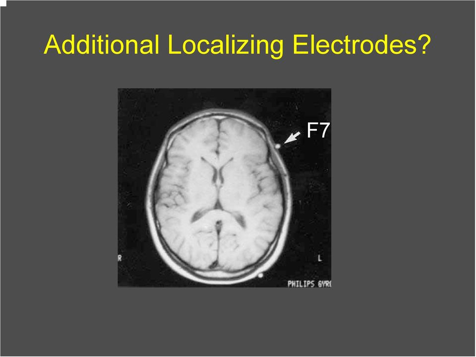
10 Additional Localizing Electrodes? F7
11 Additional Localizing Electrodes T1/T2 (Silverman) Mandibular Notch Sphenoidal Nasopharyngeal

12 Teaching Points Use correct nomenclature Understand when additional electrodes are required and where to place them Recognize the importance of accurate head measurement and electrode placement

13 Differential Amplifiers Analog and Digital The voltage displayed is the difference between the two channel inputs When there is a voltage difference between inputs, one electrode will be more negative or more positive than the other

14 Differential Amplification: Digital EEG The voltage of the displayed waveform is the algebraic sum of the difference between input one, minus the reference, and input two, minus the reference Input 1 Input 2 (F3 FCZ) - (C3 FCZ) F3 FCZ - C3 FCZ F3 - C3
 - (C3 FCZ) F3 FCZ - C3")
15 Differential Amplification For ALL EEG instruments: when input 1 is more negative than input 2, the deflection of the waveform is UP when input 2 is more negative than input 1, the deflection of the waveform is DOWN

16 Differential Amplification Teaching Points: Voltage displayed is the difference between two active electrodes In digital EEG, the system reference does not contribute to the waveforms displayed in reformatted montages Not every upward wave is generated by a surface negative potential

17 Digital EEG Acquisition Analog or paper recording Filters and amplifiers process EEG signals which drive ink-writing pens Electrical signal is continuous and uninterrupted Digital EEG Recording Source signal sampled in time at a rate required to resolve a particular signal, or waveform, as determined by engineering theory The digital signal is discontinuous

18 Digital EEG Acquisition Analog to Digital Converter ADC transforms the analog signal to a series of discrete, discontinuous data points separated by equal intervals of time. Key concepts: Sampling rate The number of amplitude levels that can be resolved (bits)

19 Sampling Rate The rate at which the waveform is sampled in order to convert it into a numerical format must be at least twice the highest frequency in the EEG waveforms to be recorded (Nyquist Theorem). Aliasing occurs when a signal is undersampled.
.")
20 Aliasing Aliasing occurs when a signal is sampled too slowly to resolve its frequency content The resulting samples form a signal whose frequency is lower than that of the original signal

21 Amplitude Resolution The number of amplitude levels is expressed in terms of bits A measure of how finely the voltage can be subdivided when measured.
22 Amplitude Resolution Too few bits make it more likely that that relatively large changes can go undetected and very small amplitude changes can be overrepresented. Minimal Standard in Canada = 12 bits, ie 2 12, (or greater) with the ability to resolve voltage to 0.5µV
23 Amplitude Resolution
24 Monitor Resolution The number of pixels in each direction that can be used to fill in points on the EEG signal Insufficient pixels will have the effect of mimicking a reduced sampling rate and displaying incomplete data Canadian guidelines require 1024 X 768, recommend 1280 X 1024
25 Teaching Points Understand the effects on waveform display of: The features of ADC, including sampling rate and vertical resolution Monitor choice (size AND resolution)
26 Calibration Analog A known voltage applied simultaneously to all inputs, each with identical sensitivity and filter settings, to detect instrument faults or setting errors Electrical and mechanical baselines Sensitivity Filters Time axis alignment Pen spacing Pen damping Noise level Paper speed Performed before and after each recording Digital A known voltage applied across all inputs to permit accurate amplitude measurement and display of recorded signals. May be manual or automatic May be performed daily or weekly or at longer intervals, dependent on lab and/or national standards Preexisting calibration file is attached to each individual recording
27 Advantages of Digital EEG Montage reformatting Editing channels Lots of channels!! Off-line manipulation of montages, filters, sensitivity and time display ( paper speed )
28 Montage Reformatting A single common reference ( system reference ) is used as the second input ( G2 ) in the differential amplifier for each channel To reformat: the value of the reference is subtracted from each electrode
29 Montage Reformatting Activity recorded at the reference is thus cancelled out and cannot contaminate the activity displayed using the various reformatting montages Input 1 Input 2 (F3 FCZ) - (C3 FCZ) F3 FCZ FCZ - C3 FCZ F3 - C3 Virtually limitless options!
30 Montage Reformatting Data in all channels may be compromised if the system reference is disrupted or is of high impedance Note: Organisation of Societies for Electrophysiological Technology and Canadian Association of Electroneurophysiology Technologists Guidelines for Digital EEG Recording
31 Digital EEG Instrumentation: Sensitivity Ratio of input voltage to the signal deflection produced Setting with a higher numerical value means lower amplification Can be adjusted on and off-line as required for clarity
32 Digital EEG Instrumentation: Sensitivity The sensitivity setting on a Digital EEG is recorded automatically and is not annotated and may not be displayed. Failure to confirm the display sensitivity may lead to inaccurate interpretation of results, for example..
33
34
35
36 Digital EEG Instrumentation: Filters Digital and Analog filters establish the bandwidth of the recording. Digital filters have no effect on the source data. There are three common approaches to digital filtering: FIR (finite impulse response) IIR (infinite impulse response)* Frequency domain filtering
37 Digital EEG Instrumentation: Filters The roll off of a digital filter is determined by the order. Order refers to the number of points that are averaged by the filter at any one time Do not assume that all filters have the same order or that the frequency response curve of a digital EEG filter is identical to that of an analog filter of the same magnitude, for example.
38 higher number = steeper roll-off
39 Digital EEG: Weakness/ Shortcomings Compatibility issues Physician as technologist Blind faith in technology Cost!
40 Compatibility Software is proprietary Conversion programs cost money Not everyone has access to the same quality of computer hardware
41 Physician as Technologist The role of the EEGer has changed from that of passive recipient of data to active manipulation of raw data choosing montages applying filters adjusting sensitivity settings
42 Blind Faith in Technology Not all software programs are equal Know your system Turnkey systems and traces as observed may be good but may not always be good for you or the patient Computers crash
43 Cost Storage is cheap BUT Upgrades can cost big money! Hint: Buy the software warranty and maybe even the hardware warranty if it s offered!
44 Electrical Safety: Safety Ensure that a proper maintenance schedule is established and adhered to Discuss safety issues with staff NEVER ignore the presence of 60 Hz contamination Infection Control: Review laboratory infection control policies in light of institutional policies Never assume that patients are not at risk in your laboratory Other potential liability issues: HV and photic stimulation in pregnancy Driving after sleep deprived EEG
45 References/ Suggested Readings Report of the Committee on Methods of Clinical Examination in Electroencephalography. EEG Clin. Neurophysiol., 10: pp , 1958 Harner P., Sannit, T. A Review of the International Ten-Twenty System of Electrode Placement grass Instrument Company 1974 McLachlan R., Young GB. Minimal Standards for Digital/Quantitative Electroencephalography in Canada. Can J Neurol. Sci. 26, p. 153, 1999 Canadian Association of Electroneurophysiology Technologists, Inc. Minimal Technical Standards 2001 Tyner F., Knott, J., Mayer, W.B., Fundamentals of EEG Technology. Volume 1. Basic Concepts and Methods. Raven Press 1983 Fisch, B. Fisch and Sphelmann s EEG Primer. Basic Principles of Digital and Analog EEG. Part A: Technical Background. Elsevier Ebersole J., Pedley, T. Current Practice of Clinical Electroencephalography, Chapters 3 and 4. Lippincott Williams & Wilkins Epstein C. Digital EEG: Trouble in Paradise? J. Clin. Neurophysiol. 23: pp , 2006 Lagerland, T. Manipulating the Magic of Digital EEG: Montage Reformatting and Filtering. Am. J. END Technol. 40: pp , 2000 Stellate Harmonie Software Reference Manual*
46
Canadian Society of Clinical Neurophysiologists (CSCN) EEG Examination
 EEG Examination") INTRODUCTION This reading list was prepared by the Chief Examiner with input from other experienced CSCN EEG examiners. The list was prepared to assist candidates in their preparation for the CSCN EEG
INTRODUCTION This reading list was prepared by the Chief Examiner with input from other experienced CSCN EEG examiners. The list was prepared to assist candidates in their preparation for the CSCN EEG
1. Oscilloscope is basically a graph-displaying device-it draws a graph of an electrical signal.
 CHAPTER 3: OSCILLOSCOPE AND SIGNAL GENERATOR 3.1 Introduction to oscilloscope 1. Oscilloscope is basically a graph-displaying device-it draws a graph of an electrical signal. 2. The graph show signal change
EXPERIMENT NUMBER 5 BASIC OSCILLOSCOPE OPERATIONS
 1 EXPERIMENT NUMBER 5 BASIC OSCILLOSCOPE OPERATIONS The oscilloscope is the most versatile and most important tool in this lab and is probably the best tool an electrical engineer uses. This outline guides
AVR127: Understanding ADC Parameters. Introduction. Features. Atmel 8-bit and 32-bit Microcontrollers APPLICATION NOTE
 Atmel 8-bit and 32-bit Microcontrollers AVR127: Understanding ADC Parameters APPLICATION NOTE Introduction This application note explains the basic concepts of analog-to-digital converter (ADC) and the
Frequency Response of Filters
 School of Engineering Department of Electrical and Computer Engineering 332:224 Principles of Electrical Engineering II Laboratory Experiment 2 Frequency Response of Filters 1 Introduction Objectives To
DIGITAL-TO-ANALOGUE AND ANALOGUE-TO-DIGITAL CONVERSION
 DIGITAL-TO-ANALOGUE AND ANALOGUE-TO-DIGITAL CONVERSION Introduction The outputs from sensors and communications receivers are analogue signals that have continuously varying amplitudes. In many systems
DAC Digital To Analog Converter
 DAC Digital To Analog Converter DAC Digital To Analog Converter Highlights XMC4000 provides two digital to analog converters. Each can output one analog value. Additional multiple analog waves can be generated
Signal Processing in So.ware and Electric Field Sensing
 Signal Processing in So.ware and Electric Field Sensing CSE 466: So.ware for Embedded Systems Winter 2009 B. Mayton University of Washington CSE & Intel Research SeaMle CSE
Building a Simulink model for real-time analysis V1.15.00. Copyright g.tec medical engineering GmbH
 g.tec medical engineering GmbH Sierningstrasse 14, A-4521 Schiedlberg Austria - Europe Tel.: (43)-7251-22240-0 Fax: (43)-7251-22240-39 office@gtec.at, http://www.gtec.at Building a Simulink model for real-time
Lab 1: The Digital Oscilloscope
 PHYSICS 220 Physical Electronics Lab 1: The Digital Oscilloscope Object: To become familiar with the oscilloscope, a ubiquitous instrument for observing and measuring electronic signals. Apparatus: Tektronix
Analog Signal Conditioning
 Analog Signal Conditioning Analog and Digital Electronics Electronics Digital Electronics Analog Electronics 2 Analog Electronics Analog Electronics Operational Amplifiers Transistors TRIAC 741 LF351 TL084
Analog and Digital Signals, Time and Frequency Representation of Signals
 1 Analog and Digital Signals, Time and Frequency Representation of Signals Required reading: Garcia 3.1, 3.2 CSE 3213, Fall 2010 Instructor: N. Vlajic 2 Data vs. Signal Analog vs. Digital Analog Signals
Department of Electrical and Computer Engineering Ben-Gurion University of the Negev. LAB 1 - Introduction to USRP
 Department of Electrical and Computer Engineering Ben-Gurion University of the Negev LAB 1 - Introduction to USRP - 1-1 Introduction In this lab you will use software reconfigurable RF hardware from National
WHY DIFFERENTIAL? instruments connected to the circuit under test and results in V COMMON.
 WHY DIFFERENTIAL? Voltage, The Difference Whether aware of it or not, a person using an oscilloscope to make any voltage measurement is actually making a differential voltage measurement. By definition,
NATIONAL COMPETENCY SKILL STANDARDS FOR PERFORMING AN ELECTROENCEPHALOGRAM
 NATIONAL COMPETENCY SKILL STANDARDS FOR PERFORMING AN ELECTROENCEPHALOGRAM Electroencephalographic (EEG) providers practice in accordance with the facility policy and procedure manual which details every
Data Acquisition Basics Lab
 Data Acquisition Basics Lab Introduction Many systems in the body can be modeled as electrical systems that interact with various organs, such as the heart, the brain, and body muscle. These systems communicate
The Effective Number of Bits (ENOB) of my R&S Digital Oscilloscope Technical Paper
 of my R&S Digital Oscilloscope Technical Paper") The Effective Number of Bits (ENOB) of my R&S Digital Oscilloscope Technical Paper Products: R&S RTO1012 R&S RTO1014 R&S RTO1022 R&S RTO1024 This technical paper provides an introduction to the signal
The Effective Number of Bits (ENOB) of my R&S Digital Oscilloscope Technical Paper Products: R&S RTO1012 R&S RTO1014 R&S RTO1022 R&S RTO1024 This technical paper provides an introduction to the signal
Analog Representations of Sound
 Analog Representations of Sound Magnified phonograph grooves, viewed from above: The shape of the grooves encodes the continuously varying audio signal. Analog to Digital Recording Chain ADC Microphone
Author: Dr. Society of Electrophysio. Reference: Electrodes. should include: electrode shape size use. direction.
 Standards for Reportin ng EMG Data Author: Dr. Roberto Merletti, Politecnico di Torino, Italy The Standards for Reporting EMG Data, written by Dr. Robertoo Merletti, are endorsed by the International Society
INTERFERENCE OF SOUND WAVES
 2011 Interference - 1 INTERFERENCE OF SOUND WAVES The objectives of this experiment are: To measure the wavelength, frequency, and propagation speed of ultrasonic sound waves. To observe interference phenomena
Lab #9: AC Steady State Analysis
 Theory & Introduction Lab #9: AC Steady State Analysis Goals for Lab #9 The main goal for lab 9 is to make the students familar with AC steady state analysis, db scale and the NI ELVIS frequency analyzer.
LEVERAGING FPGA AND CPLD DIGITAL LOGIC TO IMPLEMENT ANALOG TO DIGITAL CONVERTERS
 LEVERAGING FPGA AND CPLD DIGITAL LOGIC TO IMPLEMENT ANALOG TO DIGITAL CONVERTERS March 2010 Lattice Semiconductor 5555 Northeast Moore Ct. Hillsboro, Oregon 97124 USA Telephone: (503) 268-8000 www.latticesemi.com
Sampling Theorem Notes. Recall: That a time sampled signal is like taking a snap shot or picture of signal periodically.
 Sampling Theorem We will show that a band limited signal can be reconstructed exactly from its discrete time samples. Recall: That a time sampled signal is like taking a snap shot or picture of signal
ANALYZER BASICS WHAT IS AN FFT SPECTRUM ANALYZER? 2-1
 WHAT IS AN FFT SPECTRUM ANALYZER? ANALYZER BASICS The SR760 FFT Spectrum Analyzer takes a time varying input signal, like you would see on an oscilloscope trace, and computes its frequency spectrum. Fourier's
Lock - in Amplifier and Applications
 Lock - in Amplifier and Applications What is a Lock in Amplifier? In a nut shell, what a lock-in amplifier does is measure the amplitude V o of a sinusoidal voltage, V in (t) = V o cos(ω o t) where ω o
SUMMARY. Additional Digital/Software filters are included in Chart and filter the data after it has been sampled and recorded by the PowerLab.
 This technique note was compiled by ADInstruments Pty Ltd. It includes figures and tables from S.S. Young (2001): Computerized data acquisition and analysis for the life sciences. For further information
Multiplexing and Sampling Theory
 Multiplexing and Sampling Theory THE ECONOMY OF MULTIPLEXING Sampled-Data Systems An ideal data acquisition system uses a single ADC for each measurement channel. In this way, all data are captured in
Time series analysis Matlab tutorial. Joachim Gross
 Time series analysis Matlab tutorial Joachim Gross Outline Terminology Sampling theorem Plotting Baseline correction Detrending Smoothing Filtering Decimation Remarks Focus on practical aspects, exercises,
HYBRID FIR-IIR FILTERS By John F. Ehlers
 HYBRID FIR-IIR FILTERS By John F. Ehlers Many traders have come to me, asking me to make their indicators act just one day sooner. They are convinced that this is just the edge they need to make a zillion
Experiment #11: LRC Circuit (Power Amplifier, Voltage Sensor)
") Experiment #11: LRC Circuit (Power Amplifier, Voltage Sensor) Concept: circuits Time: 30 m SW Interface: 750 Windows file: RLC.SWS EQUIPMENT NEEDED Science Workshop Interface Power Amplifier (2) Voltage
Experiment #11: LRC Circuit (Power Amplifier, Voltage Sensor) Concept: circuits Time: 30 m SW Interface: 750 Windows file: RLC.SWS EQUIPMENT NEEDED Science Workshop Interface Power Amplifier (2) Voltage
Basics of Digital Recording
 Basics of Digital Recording CONVERTING SOUND INTO NUMBERS In a digital recording system, sound is stored and manipulated as a stream of discrete numbers, each number representing the air pressure at a
Lecture 1-6: Noise and Filters
 Lecture 1-6: Noise and Filters Overview 1. Periodic and Aperiodic Signals Review: by periodic signals, we mean signals that have a waveform shape that repeats. The time taken for the waveform to repeat
CBS RECORDS PROFESSIONAL SERIES CBS RECORDS CD-1 STANDARD TEST DISC
 CBS RECORDS PROFESSIONAL SERIES CBS RECORDS CD-1 STANDARD TEST DISC 1. INTRODUCTION The CBS Records CD-1 Test Disc is a highly accurate signal source specifically designed for those interested in making
ε: Voltage output of Signal Generator (also called the Source voltage or Applied
 Experiment #10: LR & RC Circuits Frequency Response EQUIPMENT NEEDED Science Workshop Interface Power Amplifier (2) Voltage Sensor graph paper (optional) (3) Patch Cords Decade resistor, capacitor, and
EXPERIMENT NUMBER 8 CAPACITOR CURRENT-VOLTAGE RELATIONSHIP
 1 EXPERIMENT NUMBER 8 CAPACITOR CURRENT-VOLTAGE RELATIONSHIP Purpose: To demonstrate the relationship between the voltage and current of a capacitor. Theory: A capacitor is a linear circuit element whose
Type-D EEG System for Regular EEG Clinic
 Type-D EEG System for Regular EEG Clinic Type-D EEG amplifier Specifications 1. For Type-D Amplifier Input channels: 12/24/36/48 Monopolar EEG + 12channels Bipolar EEG+12 channels PSG. Power supply: Internal
RF Measurements Using a Modular Digitizer
 RF Measurements Using a Modular Digitizer Modern modular digitizers, like the Spectrum M4i series PCIe digitizers, offer greater bandwidth and higher resolution at any given bandwidth than ever before.
Laboratory Guide. Anatomy and Physiology
 Laboratory Guide Anatomy and Physiology TBME04, Fall 2010 Name: Passed: Last updated 2010-08-13 Department of Biomedical Engineering Linköpings Universitet Introduction This laboratory session is intended
Duobinary Modulation For Optical Systems
 Introduction Duobinary Modulation For Optical Systems Hari Shanar Inphi Corporation Optical systems by and large use NRZ modulation. While NRZ modulation is suitable for long haul systems in which the
Classic EEG (ERPs)/ Advanced EEG. Quentin Noirhomme
/ Advanced EEG. Quentin Noirhomme") Classic EEG (ERPs)/ Advanced EEG Quentin Noirhomme Outline Origins of MEEG Event related potentials Time frequency decomposition i Source reconstruction Before to start EEGlab Fieldtrip (included in spm)
Classic EEG (ERPs)/ Advanced EEG Quentin Noirhomme Outline Origins of MEEG Event related potentials Time frequency decomposition i Source reconstruction Before to start EEGlab Fieldtrip (included in spm)
FAST Fourier Transform (FFT) and Digital Filtering Using LabVIEW
 and Digital Filtering Using LabVIEW") FAST Fourier Transform (FFT) and Digital Filtering Using LabVIEW Wei Lin Department of Biomedical Engineering Stony Brook University Instructor s Portion Summary This experiment requires the student to
FAST Fourier Transform (FFT) and Digital Filtering Using LabVIEW Wei Lin Department of Biomedical Engineering Stony Brook University Instructor s Portion Summary This experiment requires the student to
Q1. The graph below shows how a sinusoidal alternating voltage varies with time when connected across a resistor, R.
 Q1. The graph below shows how a sinusoidal alternating voltage varies with time when connected across a resistor, R. (a) (i) State the peak-to-peak voltage. peak-to-peak voltage...v (1) (ii) State the
FREQUENCY RESPONSE ANALYZERS
 FREQUENCY RESPONSE ANALYZERS Dynamic Response Analyzers Servo analyzers When you need to stabilize feedback loops to measure hardware characteristics to measure system response BAFCO, INC. 717 Mearns Road
Fetal monitoring on the move, from a hospital to in-home setting
 Michiel Rooijakkers MSc TU/e - Signal Processing Systems SEBAN (Smart Energy Body Area Sensor Networks for Pregnancy Monitoring) 18 th October 2011 Fetal monitoring on the move, from a hospital to in-home
Clock Recovery in Serial-Data Systems Ransom Stephens, Ph.D.
 Clock Recovery in Serial-Data Systems Ransom Stephens, Ph.D. Abstract: The definition of a bit period, or unit interval, is much more complicated than it looks. If it were just the reciprocal of the data
QUICK START GUIDE FOR DEMONSTRATION CIRCUIT 956 24-BIT DIFFERENTIAL ADC WITH I2C LTC2485 DESCRIPTION
 LTC2485 DESCRIPTION Demonstration circuit 956 features the LTC2485, a 24-Bit high performance Σ analog-to-digital converter (ADC). The LTC2485 features 2ppm linearity, 0.5µV offset, and 600nV RMS noise.
Sound Pressure Measurement
 Objectives: Sound Pressure Measurement 1. Become familiar with hardware and techniques to measure sound pressure 2. Measure the sound level of various sizes of fan modules 3. Calculate the signal-to-noise
Computer Networks and Internets, 5e Chapter 6 Information Sources and Signals. Introduction
 Computer Networks and Internets, 5e Chapter 6 Information Sources and Signals Modified from the lecture slides of Lami Kaya (LKaya@ieee.org) for use CECS 474, Fall 2008. 2009 Pearson Education Inc., Upper
Note monitors controlled by analog signals CRT monitors are controlled by analog voltage. i. e. the level of analog signal delivered through the
 DVI Interface The outline: The reasons for digital interface of a monitor the transfer from VGA to DVI. DVI v. analog interface. The principles of LCD control through DVI interface. The link between DVI
PCM Encoding and Decoding:
 PCM Encoding and Decoding: Aim: Introduction to PCM encoding and decoding. Introduction: PCM Encoding: The input to the PCM ENCODER module is an analog message. This must be constrained to a defined bandwidth
PUMPED Nd:YAG LASER. Last Revision: August 21, 2007
 PUMPED Nd:YAG LASER Last Revision: August 21, 2007 QUESTION TO BE INVESTIGATED: How can an efficient atomic transition laser be constructed and characterized? INTRODUCTION: This lab exercise will allow
Chapter 12: The Operational Amplifier
 Chapter 12: The Operational Amplifier 12.1: Introduction to Operational Amplifier (Op-Amp) Operational amplifiers (op-amps) are very high gain dc coupled amplifiers with differential inputs; they are used
Voice---is analog in character and moves in the form of waves. 3-important wave-characteristics:
 Voice Transmission --Basic Concepts-- Voice---is analog in character and moves in the form of waves. 3-important wave-characteristics: Amplitude Frequency Phase Voice Digitization in the POTS Traditional
Positive Feedback and Oscillators
 Physics 3330 Experiment #6 Fall 1999 Positive Feedback and Oscillators Purpose In this experiment we will study how spontaneous oscillations may be caused by positive feedback. You will construct an active
Data Acquisition Using NI-DAQmx
 Instructor s Portion Data Acquisition Using NI-DAQmx Wei Lin Department of Biomedical Engineering Stony Brook University Summary This experiment requires the student to use NI-DAQmx to acquire voltage
Doppler. Doppler. Doppler shift. Doppler Frequency. Doppler shift. Doppler shift. Chapter 19
 Doppler Doppler Chapter 19 A moving train with a trumpet player holding the same tone for a very long time travels from your left to your right. The tone changes relative the motion of you (receiver) and
Chapter 6: From Digital-to-Analog and Back Again
 Chapter 6: From Digital-to-Analog and Back Again Overview Often the information you want to capture in an experiment originates in the laboratory as an analog voltage or a current. Sometimes you want to
Prepared by: Paul Lee ON Semiconductor http://onsemi.com
 Introduction to Analog Video Prepared by: Paul Lee ON Semiconductor APPLICATION NOTE Introduction Eventually all video signals being broadcasted or transmitted will be digital, but until then analog video
Signal to Noise Instrumental Excel Assignment
 Signal to Noise Instrumental Excel Assignment Instrumental methods, as all techniques involved in physical measurements, are limited by both the precision and accuracy. The precision and accuracy of a
TDS5000B, TDS6000B, TDS/CSA7000B Series Acquisition Modes
 TDS5000B, TDS6000B, TDS/CSA7000B Series Acquisition Modes Tektronix oscilloscopes provide several different acquisition modes. While this gives the user great flexibility and choice, each mode is optimized
Agilent AN 1316 Optimizing Spectrum Analyzer Amplitude Accuracy
 Agilent AN 1316 Optimizing Spectrum Analyzer Amplitude Accuracy Application Note RF & Microwave Spectrum Analyzers Table of Contents 3 3 4 4 5 7 8 8 13 13 14 16 16 Introduction Absolute versus relative
In mathematics, there are four attainment targets: using and applying mathematics; number and algebra; shape, space and measures, and handling data.
 MATHEMATICS: THE LEVEL DESCRIPTIONS In mathematics, there are four attainment targets: using and applying mathematics; number and algebra; shape, space and measures, and handling data. Attainment target
Analog Filters. A common instrumentation filter application is the attenuation of high frequencies to avoid frequency aliasing in the sampled data.
 Analog Filters Filters can be used to attenuate unwanted signals such as interference or noise or to isolate desired signals from unwanted. They use the frequency response of a measuring system to alter
Basic Op Amp Circuits
 Basic Op Amp ircuits Manuel Toledo INEL 5205 Instrumentation August 3, 2008 Introduction The operational amplifier (op amp or OA for short) is perhaps the most important building block for the design of
b 1 is the most significant bit (MSB) The MSB is the bit that has the most (largest) influence on the analog output
 The MSB is the bit that has the most (largest) influence on the analog output") CMOS Analog IC Design - Chapter 10 Page 10.0-5 BLOCK DIAGRAM OF A DIGITAL-ANALOG CONVERTER b 1 is the most significant bit (MSB) The MSB is the bit that has the most (largest) influence on the analog output
CMOS Analog IC Design - Chapter 10 Page 10.0-5 BLOCK DIAGRAM OF A DIGITAL-ANALOG CONVERTER b 1 is the most significant bit (MSB) The MSB is the bit that has the most (largest) influence on the analog output
Data Cleansing for Remote Battery System Monitoring
 Data Cleansing for Remote Battery System Monitoring Gregory W. Ratcliff Randall Wald Taghi M. Khoshgoftaar Director, Life Cycle Management Senior Research Associate Director, Data Mining and Emerson Network
Introduction to Digital Audio
 Introduction to Digital Audio Before the development of high-speed, low-cost digital computers and analog-to-digital conversion circuits, all recording and manipulation of sound was done using analog techniques.
Evaluating Oscilloscope Bandwidths for Your Application
 Evaluating Oscilloscope Bandwidths for Your Application Application Note Table of Contents Introduction....1 Defining Oscilloscope Bandwidth.....2 Required Bandwidth for Digital Applications...4 Digital
How To Calculate The Power Gain Of An Opamp
 A. M. Niknejad University of California, Berkeley EE 100 / 42 Lecture 8 p. 1/23 EE 42/100 Lecture 8: Op-Amps ELECTRONICS Rev C 2/8/2012 (9:54 AM) Prof. Ali M. Niknejad University of California, Berkeley
Understanding Power Splitters
 Understanding Power Splitters How they work, what parameters are critical, and how to select the best value for your application. Basically, a 0 splitter is a passive device which accepts an input signal
Agilent Creating Multi-tone Signals With the N7509A Waveform Generation Toolbox. Application Note
 Agilent Creating Multi-tone Signals With the N7509A Waveform Generation Toolbox Application Note Introduction Of all the signal engines in the N7509A, the most complex is the multi-tone engine. This application
Timing Errors and Jitter
 Timing Errors and Jitter Background Mike Story In a sampled (digital) system, samples have to be accurate in level and time. The digital system uses the two bits of information the signal was this big
Constructing a precision SWR meter and antenna analyzer. Mike Brink HNF, Design Technologist.
 Constructing a precision SWR meter and antenna analyzer. Mike Brink HNF, Design Technologist. Abstract. I have been asked to put together a detailed article on a SWR meter. In this article I will deal
Agilent Time Domain Analysis Using a Network Analyzer
 Agilent Time Domain Analysis Using a Network Analyzer Application Note 1287-12 0.0 0.045 0.6 0.035 Cable S(1,1) 0.4 0.2 Cable S(1,1) 0.025 0.015 0.005 0.0 1.0 1.5 2.0 2.5 3.0 3.5 4.0 Frequency (GHz) 0.005
SIGNAL PROCESSING FOR EFFECTIVE VIBRATION ANALYSIS
 SIGNAL PROCESSING FOR EFFECTIVE VIBRATION ANALYSIS Dennis H. Shreve IRD Mechanalysis, Inc Columbus, Ohio November 1995 ABSTRACT Effective vibration analysis first begins with acquiring an accurate time-varying
SGN-1158 Introduction to Signal Processing Test. Solutions
 SGN-1158 Introduction to Signal Processing Test. Solutions 1. Convolve the function ( ) with itself and show that the Fourier transform of the result is the square of the Fourier transform of ( ). (Hints:
A Tutorial on the Decibel
 A Tutorial on the Decibel This tutorial combines information from several authors, including Bob DeVarney, W1ICW; Walter Bahnzaf, WB1ANE; and Ward Silver, NØAX Decibels are part of many questions in the
The Fourier Analysis Tool in Microsoft Excel
 The Fourier Analysis Tool in Microsoft Excel Douglas A. Kerr Issue March 4, 2009 ABSTRACT AD ITRODUCTIO The spreadsheet application Microsoft Excel includes a tool that will calculate the discrete Fourier
How To Understand The Nyquist Sampling Theorem
 Nyquist Sampling Theorem By: Arnold Evia Table of Contents What is the Nyquist Sampling Theorem? Bandwidth Sampling Impulse Response Train Fourier Transform of Impulse Response Train Sampling in the Fourier
RANDOM VIBRATION AN OVERVIEW by Barry Controls, Hopkinton, MA
 RANDOM VIBRATION AN OVERVIEW by Barry Controls, Hopkinton, MA ABSTRACT Random vibration is becoming increasingly recognized as the most realistic method of simulating the dynamic environment of military
Routinely DIYers opt to make themselves a passive preamp - just an input selector and a volume control.
 The First Watt B1 Buffer Preamp Nelson Pass, June 2008 Side A So here we are in the New Millennium, and thanks to Tom Holman and THX we ve got lots of gain in our electronics. More gain than some of us
A DESIGN OF DSPIC BASED SIGNAL MONITORING AND PROCESSING SYSTEM
 ISTANBUL UNIVERSITY JOURNAL OF ELECTRICAL & ELECTRONICS ENGINEERING YEAR VOLUME NUMBER : 2009 : 9 : 1 (921-927) A DESIGN OF DSPIC BASED SIGNAL MONITORING AND PROCESSING SYSTEM Salih ARSLAN 1 Koray KÖSE
Enhanced Money Market Funds Reporting
 January 20, 2016 Enhanced Money Market Funds Reporting Schwab Money Funds are making important changes to their reporting features to comply with the new Securities and Exchange (SEC) regulations. More
Sampling Theory For Digital Audio By Dan Lavry, Lavry Engineering, Inc.
 Sampling Theory Page Copyright Dan Lavry, Lavry Engineering, Inc, 24 Sampling Theory For Digital Audio By Dan Lavry, Lavry Engineering, Inc. Credit: Dr. Nyquist discovered the sampling theorem, one of
Characterizing Digital Cameras with the Photon Transfer Curve
 Characterizing Digital Cameras with the Photon Transfer Curve By: David Gardner Summit Imaging (All rights reserved) Introduction Purchasing a camera for high performance imaging applications is frequently
Table 1 Mixed-Signal Test course major topics. Mixed-signal Test and Measurement Concepts ENCT 351 What are Mixed-signal circuits
 Mixed-Signal Test Emphasis in Engineering Technology Rainer J. Fink, Jay Porter, Yong-Kyu Jung, B. Ben Zoghi Department of Engineering Technology and Industrial Distribution Texas A&M University College
MEASUREMENT UNCERTAINTY IN VECTOR NETWORK ANALYZER
 MEASUREMENT UNCERTAINTY IN VECTOR NETWORK ANALYZER W. Li, J. Vandewege Department of Information Technology (INTEC) University of Gent, St.Pietersnieuwstaat 41, B-9000, Gent, Belgium Abstract: Precision
Analog-to-Digital Voice Encoding
 Analog-to-Digital Voice Encoding Basic Voice Encoding: Converting Analog to Digital This topic describes the process of converting analog signals to digital signals. Digitizing Analog Signals 1. Sample
DIODE CIRCUITS LABORATORY. Fig. 8.1a Fig 8.1b
 DIODE CIRCUITS LABORATORY A solid state diode consists of a junction of either dissimilar semiconductors (pn junction diode) or a metal and a semiconductor (Schottky barrier diode). Regardless of the type,
Op amp DC error characteristics and the effect on high-precision applications
 Op amp DC error characteristics and the effect on high-precision applications Srudeep Patil, Member of Technical Staff, Maxim Integrated - January 01, 2014 This article discusses the DC limitations of
ELECTRON SPIN RESONANCE Last Revised: July 2007
 QUESTION TO BE INVESTIGATED ELECTRON SPIN RESONANCE Last Revised: July 2007 How can we measure the Landé g factor for the free electron in DPPH as predicted by quantum mechanics? INTRODUCTION Electron
The Calculation of G rms
 The Calculation of G rms QualMark Corp. Neill Doertenbach The metric of G rms is typically used to specify and compare the energy in repetitive shock vibration systems. However, the method of arriving
Yamaha Power Amplifier. White Paper
 Yamaha Power Amplifier White Paper August 2008 Table of Contents 1. About EEEngine...2 1.1. Introduction...2 1.2. Explanation of different amplifier topologies...2 2. Yamaha technology...5 2.1. Dual mono-amplifier
Dash 18X / Dash 18 Data Acquisition Recorder
 75 Dash 18X / Dash 18 Data Acquisition Recorder QUICK START GUIDE Supports Recorder System Software Version 3.1 1. INTRODUCTION 2. GETTING STARTED 3. HARDWARE OVERVIEW 4. MENUS & BUTTONS 5. USING THE DASH
ANIMA: Non-Conventional Interfaces in Robot Control Through Electroencephalography and Electrooculography: Motor Module
 Ninth LACCEI Latin American and Caribbean Conference (LACCEI 2011), Engineering for a Smart Planet, Innovation, Information Technology and Computational Tools for Sustainable Development, August 3-5, 2011,
Loop Bandwidth and Clock Data Recovery (CDR) in Oscilloscope Measurements. Application Note 1304-6
 in Oscilloscope Measurements. Application Note 1304-6") Loop Bandwidth and Clock Data Recovery (CDR) in Oscilloscope Measurements Application Note 1304-6 Abstract Time domain measurements are only as accurate as the trigger signal used to acquire them. Often
Loop Bandwidth and Clock Data Recovery (CDR) in Oscilloscope Measurements Application Note 1304-6 Abstract Time domain measurements are only as accurate as the trigger signal used to acquire them. Often
Advancing medical technology to help you, help others.
 Advancing medical technology to help you, help others. he Experience The Cadwell Difference Since 1979 The benefits of owning a Cadwell system are numerous. Our development team understands and delivers
Audio Tone Control Using The TLC074 Operational Amplifier
 Application Report SLOA42 - JANUARY Audio Tone Control Using The TLC74 Operational Amplifier Dee Harris Mixed-Signal Products ABSTRACT This application report describes the design and function of a stereo
Analog signals are those which are naturally occurring. Any analog signal can be converted to a digital signal.
 3.3 Analog to Digital Conversion (ADC) Analog signals are those which are naturally occurring. Any analog signal can be converted to a digital signal. 1 3.3 Analog to Digital Conversion (ADC) WCB/McGraw-Hill