Hydraulic Conductivity Tests for Soils. Hsin-yu Shan Dept. of Civil Engineering National Chiao Tung University
|
|
|
- Agnes Stone
- 7 years ago
- Views:
Transcription
1 Hydraulic Conductivity Tests for Soils Hsin-yu Shan Dept. of Civil Engineering National Chiao Tung University

2 Purpose Why do we need to know the hydraulic conductivity of soil?

3 Challenges with Hydraulic Conductivity Measurement Hydraulic conductivity of soil/rock varies over a very large range Both very high and very low hydraulic conductivity values are difficult to be measured Homogeneity and anisotropy have huge influence

4 Ranges of Hydraulic Conductivity Clay Material Intrinsic Permeability (darcy) Hydraulic Conductivity (cm/s) Silt, sandy silts, clayey sands, till Silty sands, fine sands Well-sorted sands, glacial outwash Well-sorted gravel

5 Laboratory Hydraulic Conductivity Tests Types of permeameters Flexible-wall permeameter Rigid-wall permeameter Compaction mold Thin-wall tube Consolidation cell

6
7

8 Pressure/Flow Control Devices Pressure control panel + (air compressor/pressurized gas bottle) Water columns/reservoir Both can be used to run constant head or variable head tests

9 Pressure/Flow Condition Constant Head Method Falling Head Method Rising/Falling Head Method Constant Rate of Flow

10 Pressure/Flow Control Panel Cell P. H.W. T.W. Tailwater Compressor Headwater Water Vacuum PID Permeant Deaired Water Permeameter Control Panel Cell pressure

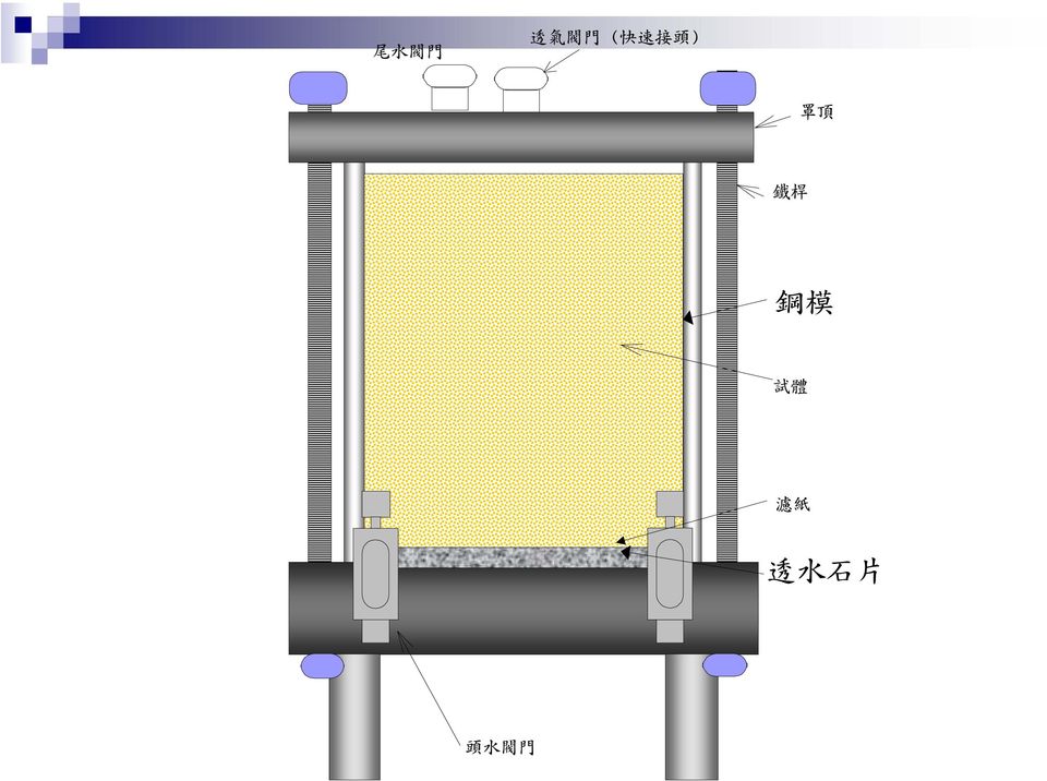
11 Constant-Head Method

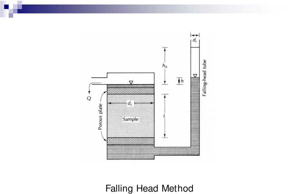
12 Falling Head Method
13 Influencing Factors of Lab Test Effective stress Hydraulic gradient Degree of saturation Chemistry of permeation liquid Volume of flow

14 Non-representative samples Sample size Fissures Voids formed during sample preparation Only becomes a problem for flexible-wall tests Smear zones Normally ~ 1/16 in Growth of micro-organisms Temperature Viscosity and density

15 Effective Stress k e σ

16 Selection of Effective Stress Based on the field condition Unit weight of soil ~ 16 kn/m 3 (130 pcf) Unit weight of solid waste ~ 5.5 kn/m 3 (45 pcf) Based on the test standards No specific stress level is specified in ASTM D5084
 Based on the test standards No specific")
17 Hydraulic Gradient Large hydraulic gradient will cause: Finer particles to migrate downstream and clogged the pores Particle distribution specimen becomes not uniform Hydraulic gradient should be comparable to that in the field usually low

18 Using low hydraulic gradient is timeconsuming ASTM D5084 suggests a maximum hydraulic gradient of 30 for soils with k 1 x 10⁻⁷ cm/s

19 Degree of Saturation k S r 100%

20 Air bubbles reduce the effective area to conduct flow Apply backpressure to saturate the specimen ASTM D5084 does not specify the magnitude of backpressure Usually apply backpressure up to kpa (~ psi)

21 Chemistry of Pore Liquid Effect of diffuse double layer Concentration of electrolyte Valence of cations Dielectric constant of liquid Importance of hydration liquid
22 Chemical Attack of Chemicals to Clays Double Layer Principles Permeation liquids Solution of salts Acid and Base Dissolutioning of finer particles Solutions of dilute organic chemicals NAPL Landfill leachate
23 T Thickness of DDL Distance controlling k Negatively charged clay particle T Flow T
24 Principle of Diffuse Double Layer D = dielectric Constant of liquid n 0 = concentration of electrolyte v = valence of cations T D n v 0 2 k = hydraulic conductivity k n v 0 2 D
25 Pore Volumes of Flow Pore Volume, P.V. = total volume of voids of the specimen Must allow enough liquid to flow through the specimen to be sure that the interaction between the soil and the pore liquid has stabilized
26 Termination Criteria The test should be conducted long enough in order to obtain reliable results Basic requirements are: Reasonable outflow/inflow ratio (q out /q in ) [ASTM D5084: ] Stable k over a certain period Neither increasing nor decreasing ASTM D5084: 2 to 4 consistent k values
27 In-Situ Hydraulic Conductivity Tests Borehole k test Porous Probes Infiltrometer Open single/double ring infiltrometer Sealed single/double ring infiltrometer Lysimeter
28 Two-Stage Borehole Test Developed by Boutwell (Soil Testing Engineers, 1983) Two testing stages, each its own bulb of saturation Obtain different rate of infiltration Can determine hydraulic conductivity in both vertical and horizontal direction
29
30 Two Stages of Testing
31 First stage Casing is driven to the bottom of the borehole Obtain hydraulic conductivity k 1 by falling head test Second stage The casing is driven deeper and then the infiltrometer is reassembled Obtain hydraulic conductivity k 2 by falling head test
32 Determine parameter m from k 1 and k 2 Determine hydraulic conductivity k v and k h k k 2 1 = L ln[ D ml ln[ D + + L 2 1+ ( ) ] D ml 2 1+ ( ) D m ] 1 k v = k1 k 1 m h = mk
33 Advantages Inexpensive ( < US$2000 ) Easy to install Can determine both vertical and horizontal hydraulic conductivity Can be used for soils of low hydraulic conductivity ( 10-9 cm/s) Can be conducted on slope
34 Disadvantages The volume of soil tested is small The absorption of water by soil is not taken into account when the soil is unsaturated Long test period required (it takes several days to weeks for the flow to become steady when k < 10-7 cm/s)
35 Constant-Head Borehole Permeameter Guelph Permeameter (Reynolds and Elrick 1985, 1986; Soilmoisture Equipment Corp.) Similar to borehole tests The absorption of water by soil is taken into account (sorptive number α)
36 (a) Guelph permeameter (b) Bulb of saturation
37 Important assumptions: The soil is homogeneous and isotropic The soil is saturated No volume change occurred during testing The assumption of isotropy may lead to significant
38 Advantages Inexpensive equipment ( < US$3000 ) Easy to install and assemble The absorption of water by soil is taken into account Relatively short testing period (a few hours to a few days) Relatively good for measuring vertical hydraulic conductivity Can measure hydraulic conductivity of soil at a little deeper depth
39 Disadvantages The volume of soil tested is small Not suitable for determining horizontal hydraulic conductivity Not suitable to be used for soils of low hydraulic conductivity (k < 10-7 cm/s)
40 Porous Probe Porous probes have been used to measure in-situ k for quite some time BAT permeameter (Torstensson 1984) was designed for unsaturated, low permeability soil Flow rate and pore pressure are computed using Boyle s law
41
42 Assumptions: Soils are homogeneous, isotropic, and incompressible Neglect the adsorption of water Temperature is constant through out the test Hvorslev s (1949) equations is valid
43 Advantages Easy to install Short testing time for soils of higher hydraulic conductivity (usually a few minutes to a few hours) Pore pressure can be measured at the same time Can be used for soils of low hydraulic conductivity ( cm/s) Suitable for determining vertical hydraulic conductivity Can measure hydraulic conductivity of soil deeper below ground surface
44 Disadvantages The equipment is relatively expensive ( > US$6000) The volume of soil tested is very small Not suitable for determining horizontal hydraulic conductivity The absorption of water by soil is not taken into account when the soil is unsaturated
45 Air-Entry Permeameter The test is performed on the ground surface Assumptions: Soils are homogeneous, isotropic, and incompressible Soils behind the wetting front are saturated
46
47
48 Advantages Moderate cost ( < US$ 3000 ) Short testing time (reached equilibrium within a few hours to a few days) Can be used for soils of low hydraulic conductivity ( cm/s) Suitable for determining vertical hydraulic conductivity
49 Disadvantages Volume of soil tested is relatively small The wetting front is within a few centimeters below the ground surface Cannot be performed on slope
50 Ring Infiltrometer Has been used to determine hydraulic conductivity of shallow soil for a long time Four types of setup: Open single- or double- ring infiltrometer (most frequently used) Sealed single- or double- ring infiltrometer Hydraulic gradient is often assumed to be 1
51 Open, Single-Ring Infiltrometer Most simple infiltrometer Assumptions: Soils are homogeneous, isotropic, and incompressible Soils behind the wetting front are saturated No leakage between the ring and soil
52 The flow of water for single-ring infiltrometer is not one-dimensional over estimate hydraulic conductivity Not suitable for soils with k < cm/s due to the relative amount of evaporation
53 Tensiometer A B H D
54 Advantages Low equipment cost ( < US$ 1000 ) Easy to install Can manufacture large-size infiltrometer to test larger volume of soil Suitable for determining vertical hydraulic conductivity
55 Disadvantages Not suitable for soils with k < cm/s Need to correct for evaporation Need to correct for non-one-dimensional flow Relatively long testing time (a few weeks to a few months for soils with k < cm/s) Cannot be performed on steep slope
56 Open, Double-Ring Infiltrometer Most often infiltrometer Assumptions: Soils are homogeneous, isotropic, and incompressible Soils behind the wetting front are saturated No leakage between the ring and soil Flow of water from inner ring is onedimensionally downward
57 Not suitable for soils with k < cm/s due to the relative amount of evaporation Use the flow rate of inner ring to compute infiltration rate and hydraulic conductivity
58
59 Tensiometer A B H D
60
61
62
63 Advantages Inexpensive equipment ( < US$ 1000 ) Suitable for measurement of vertical hydraulic conductivity The flow of water from inner ring can be treated as one-dimensional
64 Disadvantages Not suitable for soils of low hydraulic conductivity (< 10-7 cm/s) Need to correct for evaporation Relatively long testing time (a few days to a few weeks for soils with k < cm/s) [shorter than single-ring infiltrometer] Cannot be performed on steep slope
65 Sealed, Single-Ring Infiltrometer Same basic assumptions as those for open ring infiltrometers The inner ring is seal Do not need to correction for evaporation Particularly suitable for soils low hydraulic conductivity Need to correct for non-one-dimensional flow
66 A B H D
67 Advantages Relatively low cost ( < US$ 1000 ) Only suitable for determining vertical hydraulic conductivity Suitable for soils low hydraulic conductivity ( cm/s)
68 Disadvantages Volume of soil tested is still small the diameter of the ring is less than 1 m Need to correct for the flow direction of infiltrating water Relatively long testing time (a few weeks to a few months) Not suitable for sloping ground surface
69 Sealed Double Ring Infiltrometer, SDRI Same basic assumptions as those for open ring infiltrometers Do not need to consider the volume change of soil before the flow rate becomes stable The inner ring is seal Do not need to correction for evaporation Particularly suitable for soils low hydraulic conductivity
70 Measure vertical hydraulic conductivity Do not need to correct for direction of flow flow from inner ring can be treated as one-dimensionally downward
71 Tensiometer A B H D
72
73
74 Advantages Moderate cost ( < US$ 2500 ) Suitable for low permeability soils (< 10-8 cm/s) Flow of inner ring can be treated as onedimensional Dimension of outer ring is relatively large
75 Disadvantages Relatively long testing time (a few weeks to a few months) Not applicable on sloping ground surface
76 Underdrain Installed underneath the soil of which hydraulic conductivity is to be measured Collect water infiltrated through the soil to compute hydraulic conductivity Only suitable for test pad constructed of compacted soil
77 Large area of water ponds on the soil errors caused by assumption of onedimensional flow is small Water in the soil can be assumed to be under positive pressure the hydraulic gradient is better defined
78 Advantages Low equipment cost Applicable for determining vertical hydraulic conductivity Larger volume of soil tested Does not disturb the soil sample
79 Disadvantages Need construction work for installation Relatively long testing time (a few days to a few weeks for soils with k < cm/s)
80 Lab Test vs. In-Situ Test Advantages of lab test Particularly relevant for compacted soils Can conveniently test with different boundary conditions Economical to perform Many tests can be performed at the same time
81 Disadvantages of lab test Small specimen size Problems with sample selection Tend to select good sample for testing Effect of sample disturbance Flow may be in the direction that is not the most critical
82 Grain shape and orientation can affect the isotropy or anisotropy of a sediment
83 Advantages of in-situ test Test a large volume of soil Minimized sample disturbance More appropriate flow direction, more relevant results
84 Disadvantages of in-situ test Expensive to perform Time consuming Test procedure is ill-defined Problems with data reduction
85 Generalized Comments on k Tests Samples should be representative Orient flow direction properly Constant head test is preferable (constant volume during testing) Min. edge voids and smear zones Use relevant pore liquid
86 Avoid getting air bubbles Avoid the growth of micro-organism Use appropriate hydraulic gradient Monitor stress-induced volume change
87 Hydraulic Conductivity of Compacted Soils Earth dams Landfill liners (bottom liners and final covers) Surface impoundment liners Lining of canals
88 Compaction Curves Modified Proctor Zero air voids curve γ d Standard Proctor w
89 Zero air voids curve S r = 100% γ d 70% 50% 80% Line of optimums w
90 Types of Compaction Impact Proctor compaction test (lab) Dynamic compaction (field) Kneading Remolded Harvard miniature compaction (lab) Sheepfoot roller (field) Padfoot roller (field)
91 Static Piston Smooth wheel roller (field) Rubber tire roller Vibratory - Vibrator Vibratory smooth wheel roller (field)
92 Effect on Undrained Shear Strength γ d q u w opt w% w%
93 w opt q u w% u w% (-)
94 Stress-Strain Behavior γ d B C A w opt w% B σ A C ε
95 γ d A B w opt log w% σ A e B
96 γ d w opt w% k w%
CONSTANT HEAD AND FALLING HEAD PERMEABILITY TEST
 CONSTANT HEAD AND FALLING HEAD PERMEABILITY TEST 1 Permeability is a measure of the ease in which water can flow through a soil volume. It is one of the most important geotechnical parameters. However,
EXPERIMENT 10 CONSTANT HEAD METHOD
 EXPERIMENT 10 PERMEABILITY (HYDRAULIC CONDUCTIVITY) TEST CONSTANT HEAD METHOD 106 Purpose: The purpose of this test is to determine the permeability (hydraulic conductivity) of a sandy soil by the constant
METHOD OF TEST FOR DETERMINATION OF PERMEABILITY OF GRANULAR SOILS
 Laboratory Testing Manual Date: 99 06 21 Page 1 of 7 METHOD OF TEST FOR DETERMINATION OF PERMEABILITY OF GRANULAR SOILS 1. SCOPE 1.1 This method covers the determination of the coefficient of permeability
CHAPTER: 6 FLOW OF WATER THROUGH SOILS
 CHAPTER: 6 FLOW OF WATER THROUGH SOILS CONTENTS: Introduction, hydraulic head and water flow, Darcy s equation, laboratory determination of coefficient of permeability, field determination of coefficient
The University of Toledo Soil Mechanics Laboratory
 The University of Toledo Soil Mechanics Laboratory Permeability Testing - 1 Constant and Falling Head Tests Introduction In 1856 the French engineer Henri D arcy demonstrated by experiment that it is possible
Soil Suction. Total Suction
 Soil Suction Total Suction Total soil suction is defined in terms of the free energy or the relative vapor pressure (relative humidity) of the soil moisture. Ψ = v RT ln v w 0ω v u v 0 ( u ) u = partial
DIRECT SHEAR TEST SOIL MECHANICS SOIL MECHANICS LABORATORY DEPARTMENT OF CIVIL ENGINEERING UNIVERSITY OF MORATUWA SRI LANKA
 DIRECT SHEAR TEST SOIL MECHANICS SOIL MECHANICS LABORATORY DEPARTMENT OF CIVIL ENGINEERING UNIVERSITY OF MORATUWA SRI LANKA DIRECT SHEAR TEST OBJEVTIVES To determine the shear strength parameters for a
CEEN 162 - Geotechnical Engineering Laboratory Session 7 - Direct Shear and Unconfined Compression Tests
 PURPOSE: The parameters of the shear strength relationship provide a means of evaluating the load carrying capacity of soils, stability of slopes, and pile capacity. The direct shear test is one of the
Figure 2.31. CPT Equipment
 Soil tests (1) In-situ test In order to sound the strength of the soils in Las Colinas Mountain, portable cone penetration tests (Japan Geotechnical Society, 1995) were performed at three points C1-C3
PERMEABILITY TEST. To determine the coefficient of permeability of a soil using constant head method.
 PERMEABILITY TEST A. CONSTANT HEAD OBJECTIVE To determine the coefficient of permeability of a soil using constant head method. need and Scope The knowledge of this property is much useful in solving problems
SOUTHWEST FLORIDA WATER MANAGEMENT DISTRICT RESOURCE REGULATION TRAINING MEMORANDUM
 SOUTHWEST FLORIDA WATER MANAGEMENT DISTRICT RESOURCE REGULATION TRAINING MEMORANDUM DATE: December 04, 1996 This document is subject to change. If in doubt, verify current status with Technical Services
Soil Mechanics. Outline. Shear Strength of Soils. Shear Failure Soil Strength. Laboratory Shear Strength Test. Stress Path Pore Pressure Parameters
 Soil Mechanics Shear Strength of Soils Chih-Ping Lin National Chiao Tung Univ. cplin@mail.nctu.edu.tw 1 Outline Shear Failure Soil Strength Mohr-Coulomb Failure Criterion Laboratory Shear Strength Test
KWANG SING ENGINEERING PTE LTD
 KWANG SING ENGINEERING PTE LTD 1. INTRODUCTION This report represents the soil investigation works at Aljunied Road / Geylang East Central. The objective of the soil investigation is to obtain soil parameters
Interpretation of clogging effects on the hydraulic behavior of ion treated geotextiles
 9 th International Conference on Geosynthetics, Brazil, 2010 Interpretation of clogging effects on the hydraulic behavior of ion treated geotextiles Lee, K. W. Department of Civil Engineering, Dongseo
Trench Rescue by Buddy Martinette
 Trench Rescue by Buddy Martinette SOIL TYPE AND TESTING It is imperative that rescue personnel understand soil types and testing procedures if the want to be competent at trench rescue operations. Determining
For Water to Move a driving force is needed
 RECALL FIRST CLASS: Q K Head Difference Area Distance between Heads Q 0.01 cm 0.19 m 6cm 0.75cm 1 liter 86400sec 1.17 liter ~ 1 liter sec 0.63 m 1000cm 3 day day day constant head 0.4 m 0.1 m FINE SAND
UNDER DRAINAGE AND FILTER DESIGN
 UNDER DRAINAGE AND FILTER DESIGN Tailings and HLP Workshop 28 April to 1 May 2010 INTRODUCTION The internal drainage is of crucial importance to the reliability and safety of a tailings dam throughout
c. Borehole Shear Test (BST): BST is performed according to the instructions published by Handy Geotechnical Instruments, Inc.
: BST is performed according to the instructions published by Handy Geotechnical Instruments, Inc.") Design Manual Chapter 6 - Geotechnical 6B - Subsurface Exploration Program 6B-2 Testing A. General Information Several testing methods can be used to measure soil engineering properties. The advantages,
Design Manual Chapter 6 - Geotechnical 6B - Subsurface Exploration Program 6B-2 Testing A. General Information Several testing methods can be used to measure soil engineering properties. The advantages,
Period #16: Soil Compressibility and Consolidation (II)
") Period #16: Soil Compressibility and Consolidation (II) A. Review and Motivation (1) Review: In most soils, changes in total volume are associated with reductions in void volume. The volume change of the
Period #16: Soil Compressibility and Consolidation (II) A. Review and Motivation (1) Review: In most soils, changes in total volume are associated with reductions in void volume. The volume change of the
TECHNICAL SPECIFICATIONS CEMENT-BENTONITE SLURRY TRENCH CUTOFF WALL
 TECHNICAL SPECIFICATIONS CEMENT-BENTONITE SLURRY TRENCH CUTOFF WALL SCOPE This section of the specifications includes requirements for the Slurry Trench Cutoff Wall and related work as indicated on the
14.330 SOIL MECHANICS Assignment #4: Soil Permeability.
 Geotechnical Engineering Research Laboratory One University Avenue Lowell, Massachusetts 01854 Edward L. Hajduk, D.Eng, PE Lecturer PA105D Tel: (978) 94 2621 Fax: (978) 94 052 e mail: Edward_Hajduk@uml.edu
Determination of Thermal Conductivity of Coarse and Fine Sand Soils
 Proceedings World Geothermal Congress Bali, Indonesia, - April Determination of Thermal Conductivity of Coarse and Fine Sand Soils Indra Noer Hamdhan 1 and Barry G. Clarke 2 1 Bandung National of Institute
INTRODUCTION TO SOIL MODULI. Jean-Louis BRIAUD 1
 INTRODUCTION TO SOIL MODULI By Jean-Louis BRIAUD 1 The modulus of a soil is one of the most difficult soil parameters to estimate because it depends on so many factors. Therefore when one says for example:
1.72, Groundwater Hydrology Prof. Charles Harvey Lecture Packet #2: Aquifers, Porosity, and Darcy s Law. Lake (Exposed Water Table)
") 1.72, Groundwater Hydrology Prof. Charles Harvey Lecture Packet #2: Aquifers, Porosity, and Darcy s Law Precipitation Infiltration Lake (Exposed Water Table) River Water table Saturated zone - Aquifer
1.72, Groundwater Hydrology Prof. Charles Harvey Lecture Packet #2: Aquifers, Porosity, and Darcy s Law Precipitation Infiltration Lake (Exposed Water Table) River Water table Saturated zone - Aquifer
The University of Toledo Soil Mechanics Laboratory
 The University of Toledo Soil Mechanics Laboratory 1 Soil Moisture-Density Relationship Standard and Modified Proctor Tests Introduction For earthork construction it is important to compact soils to a
Embankment Consolidation
 Embankment Consolidation 36-1 Embankment Consolidation In this tutorial, RS2 is used for a coupled analysis of a road embankment subject to loading from typical daily traffic. Model Start the RS2 9.0 Model
Drained and Undrained Conditions. Undrained and Drained Shear Strength
 Drained and Undrained Conditions Undrained and Drained Shear Strength Lecture No. October, 00 Drained condition occurs when there is no change in pore water pressure due to external loading. In a drained
Geotechnical Properties of Fly Ash and Soil Mixtures for Use in Highway Embankments
 World of Coal Ash (WOCA) Conference - May 9-12, 2011, in Denver, CO, USA http://www.flyash.info/ Geotechnical Properties of Fly Ash and Soil Mixtures for Use in Highway Embankments Fabio Santos 1, Lin
Laboratory and Field Performance Assessment of Geocomposite Alternative to Gravel Drainage Overliner in Heap Leach Pads
 Laboratory and Field Performance Assessment of Geocomposite Alternative to Gravel Drainage Overliner in Heap Leach Pads Aigen Zhao, PhD, PE, GSE Environmental, LLC, USA Mark Harris, GSE Environmental,
USE OF GEOSYNTHETICS FOR FILTRATION AND DRAINAGE
 USE OF GEOSYNTHETICS FOR FILTRATION AND DRAINAGE Prof. G L Sivakumar Babu Department of Civil Engineering Indian Institute of Science Bangalore 560012 Functions of a Filter Retain particles of the base
Soil Mechanics. Soil Mechanics
 Soil is the most misunderstood term in the field. The problem arises in the reasons for which different groups or professions study soils. Soil scientists are interested in soils as a medium for plant
COSMOS 2012: Earthquakes in Action COSMOS 2012
 COSMOS 2012 What is SFSI and why is it important? Soil issues in Earthquakes Structures where SFSI important Retaining structures (lateral earth pressure) Foundations (spread and pile footings, bearing
Fluid Mechanics: Static s Kinematics Dynamics Fluid
 Fluid Mechanics: Fluid mechanics may be defined as that branch of engineering science that deals with the behavior of fluid under the condition of rest and motion Fluid mechanics may be divided into three
Stormwater Management Design Brief. Proposed Commercial Redevelopment 5830 Hazeldean Road Ottawa (Stittsville), Ontario.
, Ontario.") Stormwater Management Design Brief Proposed Commercial Redevelopment 5830 Hazeldean Road Ottawa (Stittsville), Ontario Prepared For: 1319 Kanata Tires & Rims June 30, 2015 Report No: FS-15-013-REP.02 Stormwater
Stormwater Management Design Brief Proposed Commercial Redevelopment 5830 Hazeldean Road Ottawa (Stittsville), Ontario Prepared For: 1319 Kanata Tires & Rims June 30, 2015 Report No: FS-15-013-REP.02 Stormwater
6. Base your answer to the following question on the graph below, which shows the average monthly temperature of two cities A and B.
 1. Which single factor generally has the greatest effect on the climate of an area on the Earth's surface? 1) the distance from the Equator 2) the extent of vegetative cover 3) the degrees of longitude
GEOSYNTHETICS ENGINEERING: IN THEORY AND PRACTICE
 GEOSYNTHETICS ENGINEERING: IN THEORY AND PRACTICE Prof. J. N. Mandal Department of civil engineering, IIT Bombay, Powai, Mumbai 400076, India. Tel.022-25767328 email: cejnm@civil.iitb.ac.in Module - 4
Procedure for the Determination of the Permeability of Clayey Soils in a Triaxial Cell Using the Accelerated Permeability Test
 Procedure for the Determination of the Permeability of Clayey Soils in a Triaxial Cell Using the Accelerated Permeability Test R&D Technical Report P1-398/TR/2 Dr E. J Murray Research Contractor: Murray
SOIL-LIME TESTING. Test Procedure for. TxDOT Designation: Tex-121-E 1. SCOPE 2. APPARATUS 3. MATERIALS TXDOT DESIGNATION: TEX-121-E
 Test Procedure for SOIL-LIME TESTING TxDOT Designation: Tex-121-E Effective Date: August 2002 1. SCOPE 1.1 This method consists of three parts. 1.1.1 Part I determines the unconfined compressive strength
GROUNDWATER FLOW NETS Graphical Solutions to the Flow Equations. One family of curves are flow lines Another family of curves are equipotential lines
 GROUNDWTER FLOW NETS Graphical Solutions to the Flow Equations One family of curves are flow lines nother family of curves are equipotential lines B C D E Boundary Conditions B and DE - constant head BC
Lecture 21. Compacted soil liners
 Lecture 21 Compacted soil liners TOWN OF BOURNE, ISWM DEPARTMENT LANDFILL LINER SYSTEM, PHASE 3 FALL 2000, View of the placement of the low permeability soil. See http://www.townofbourne.com/town%20offices/iswm/layer2.htm.
product manual HS-4210 HS-4210_MAN_09.08 Digital Static Cone Penetrometer
 HS-4210_MAN_09.08 product manual HS-4210 Digital Static Cone Penetrometer Introduction This Manual covers the measurement of bearing capacity using the Humboldt Digital Static Cone Penetrometer (DSCP).
Topic 8: Open Channel Flow
 3.1 Course Number: CE 365K Course Title: Hydraulic Engineering Design Course Instructor: R.J. Charbeneau Subject: Open Channel Hydraulics Topics Covered: 8. Open Channel Flow and Manning Equation 9. Energy,
When the fluid velocity is zero, called the hydrostatic condition, the pressure variation is due only to the weight of the fluid.
 Fluid Statics When the fluid velocity is zero, called the hydrostatic condition, the pressure variation is due only to the weight of the fluid. Consider a small wedge of fluid at rest of size Δx, Δz, Δs
4.3 Results... 27 4.3.1 Drained Conditions... 27 4.3.2 Undrained Conditions... 28 4.4 References... 30 4.5 Data Files... 30 5 Undrained Analysis of
 Table of Contents 1 One Dimensional Compression of a Finite Layer... 3 1.1 Problem Description... 3 1.1.1 Uniform Mesh... 3 1.1.2 Graded Mesh... 5 1.2 Analytical Solution... 6 1.3 Results... 6 1.3.1 Uniform
#4.43 HYDRAULIC WASTEWATER LOADING RATES TO SOIL. E.J. Tyler* ABSTRACT INTRODUCTION
 HYDRAULIC WASTEWATER LOADING RATES TO SOIL #4.43 E.J. Tyler* ABSTRACT Onsite wastewater infiltration rate into soil depends on the nature of soil clogging and soil characteristics. The rate of transmission
Liner system design for tailings impoundments and heap leach pads
 Liner system design for tailings impoundments and heap leach pads John F. Lupo, Ph.D., P.E. AMEC E&E TAILINGS & MINE WASTE 08, VAIL Liner Systems Liner systems Environmental containment of process solutions
FUNDAMENTALS OF CONSOLIDATION
 FUNDAMENTALS OF CONSOLIDATION SAND (Vertical Stress Increase) CLAY CONSOLIDATION: Volume change in saturated soils caused by the expulsion of pore water from loading. Saturated Soils: causes u to increase
ENCE 4610 Foundation Analysis and Design
 This image cannot currently be displayed. ENCE 4610 Foundation Analysis and Design Shallow Foundations Total and Differential Settlement Schmertmann s Method This image cannot currently be displayed. Strength
Technical Note by G.L. Sivakumar Babu, H. Sporer, H. Zanzinger, and E. Gartung SELF-HEALING PROPERTIES OF GEOSYNTHETIC CLAY LINERS
 Technical Note by G.L. Sivakumar Babu, H. Sporer, H. Zanzinger, and E. Gartung SELF-HEALING PROPERTIES OF GEOSYNTHETIC CLAY LINERS ABSTRACT: The sealing effect and containment of moisture in landfill covers
FIELD PERMEABILITY TESTING FOR A RCRA LANDFILL FINAL COVER
 Reprinted from Proceedings of Hazmacon '87 Santa Clara, California April 22, 1987 FIELD PERMEABILITY TESTING FIELD PERMEABILITY TESTING Andrew M. Petsonk Walter Romanowski Vince Richards B.A.T. Envitech
Analysis of Double-Ring Infiltration Techniques and Development of a Simple Automatic Water Delivery System
 2005 Plant Management Network. Accepted for publication 25 April 2005. Published. Analysis of Double-Ring Infiltration Techniques and Development of a Simple Automatic Water Delivery System Justin H. Gregory,
Constant Rate of Strain Consolidation with Radial Drainage
 Geotechnical Testing Journal, Vol. 26, No. 4 Paper ID GTJ10173_264 Available online at: www.astm.org Tian Ho Seah 1 and Teerawut Juirnarongrit 2 Constant Rate of Strain Consolidation with Radial Drainage
APPENDIX G SETTLEMENT
 APPENDIX G SETTLEMENT TABLE OF CONTENTS G.1 IN T R O D U C T IO N... 1 G.2 MATERIAL PLACEMENT AND COMPACTION... 1 G.2.1 Incom pressible M aterials... 1 G.2.2 Compressible Materials... 2 G.2.3 Soil P lacem
Theoretical and Experimental Modeling of Multi-Species Transport in Soils Under Electric Fields
 United States National Risk Management Environmental Protection Research Laboratory Agency Cincinnati, OH 45268 Research and Development EPA/6/SR-97/54 August 997 Project Summary Theoretical and Experimental
Soil Mechanics SOIL STRENGTH page 1
 Soil Mechanics SOIL STRENGTH page 1 Contents of this chapter : CHAPITRE 6. SOIL STRENGTH...1 6.1 PRINCIPAL PLANES AND PRINCIPAL STRESSES...1 6.2 MOHR CIRCLE...1 6.2.1 POLE METHOD OF FINDING STRESSES ON
GEOTECHNICAL ENGINEERING FORMULAS. A handy reference for use in geotechnical analysis and design
 GEOTECHNICAL ENGINEERING FORMULAS A handy reference for use in geotechnical analysis and design TABLE OF CONTENTS Page 1. SOIL CLASSIFICATION...3 1.1 USCS: Unified Soil Classification System...3 1.1.1
Strength of Concrete
 Strength of Concrete In concrete design and quality control, strength is the property generally specified. This is because, compared to most other properties, testing strength is relatively easy. Furthermore,
Specification Guidelines: Allan Block Modular Retaining Wall Systems
 Specification Guidelines: Allan Block Modular Retaining Wall Systems The following specifications provide Allan Block Corporation's typical requirements and recommendations. At the engineer of record's
To measure the solubility of a salt in water over a range of temperatures and to construct a graph representing the salt solubility.
 THE SOLUBILITY OF A SALT IN WATER AT VARIOUS TEMPERATURES 2007, 1995, 1991 by David A. Katz. All rights reserved. Permission for academic use provided the original copyright is included. OBJECTIVE To measure
01 The Nature of Fluids
 01 The Nature of Fluids WRI 1/17 01 The Nature of Fluids (Water Resources I) Dave Morgan Prepared using Lyx, and the Beamer class in L A TEX 2ε, on September 12, 2007 Recommended Text 01 The Nature of
Module 1 : Site Exploration and Geotechnical Investigation. Lecture 5 : Geophysical Exploration [ Section 5.1 : Methods of Geophysical Exploration ]
![Module 1 : Site Exploration and Geotechnical Investigation. Lecture 5 : Geophysical Exploration [ Section 5.1 : Methods of Geophysical Exploration ]](/thumbs/40/20679662.jpg "Module 1 : Site Exploration and Geotechnical Investigation. Lecture 5 : Geophysical Exploration [ Section 5.1 : Methods of Geophysical Exploration ]") Objectives In this section you will learn the following General Overview Different methods of geophysical explorations Electrical resistivity method Seismic refraction method 5 Geophysical exploration
Objectives In this section you will learn the following General Overview Different methods of geophysical explorations Electrical resistivity method Seismic refraction method 5 Geophysical exploration
Lab 1 Concrete Proportioning, Mixing, and Testing
 Lab 1 Concrete Proportioning, Mixing, and Testing Supplemental Lab manual Objectives Concepts Background Experimental Procedure Report Requirements Discussion Prepared By Mutlu Ozer Objectives Students
PHYSICAL AND PLASTICITY CHARACTERISTICS
 0 PHYSICAL AND PLASTICITY CHARACTERISTICS EXPERIMENTS #1-5 CE 3143 October 7, 2003 Group A David Bennett 1 TABLE OF CONTENTS 1. Experiment # 1: Determination of Water Content (August 26, 2003) pp. 1-3
LABORATORY II. PLASTICITY - Atterberg limits. w L - Cone test, Cassagrande test
 LABORATORY II. PLASTICITY - Atterberg limits w L - Cone test, Cassagrande test Consistency - limits I P w L w P Is plasticity important? Smectite Structure Tetrahedral layer Octahedral layer Tetrahedral
SHORE A DUROMETER AND ENGINEERING PROPERTIES
 SHORE A DUROMETER AND ENGINEERING PROPERTIES Written by D.L. Hertz, Jr. and A.C. Farinella Presented at the Fall Technical Meeting of The New York Rubber Group Thursday, September 4, 1998 by D.L. Hertz,
VOLUME III GEOLOGY, HYDROGEOLOGY & GEOTECHNICAL REPORT CAPITAL REGION RESOURCE RECOVERY CENTRE
 2.0 SITE INVESTIGATION METHODOLOGY The following section summarizes the Site investigation methodology applied during the subsurface investigation and hydrogeological assessment completed at the CRRRC
1.34 WASTE CONTAINMENT AND SITE REMEDIATION TECHNOLOGY TAKE-HOME FINAL EXAM DUE FRIDAY MAY 7, 2004 AT 9:30 AM
 1.34 WASTE CONTAINMENT AND SITE REMEDIATION TECHNOLOGY TAKE-HOME FINAL EXAM DUE FRIDAY MAY 7, 2004 AT 9:30 AM This is an open-book exam, but the work should be yours alone. Please do not work with others
INDIRECT METHODS SOUNDING OR PENETRATION TESTS. Dr. K. M. Kouzer, Associate Professor in Civil Engineering, GEC Kozhikode
 INDIRECT METHODS SOUNDING OR PENETRATION TESTS STANDARD PENETRATION TEST (SPT) Reference can be made to IS 2131 1981 for details on SPT. It is a field edtest to estimate e the penetration e resistance
NUMERICAL ANALYSIS OF SEEPAGE THROUGH EMBANKMENT DAMS (CASE STUDY: KOCHARY DAM, GOLPAYEGAN)
") NUMERICAL ANALYSIS OF SEEPAGE THROUGH EMBANKMENT DAMS (CASE STUDY: KOCHARY DAM, GOLPAYEGAN) *Reza Naghmehkhan Dahande 1 and Ahmad Taheri 2 1 Department of Civil Engineering-Water Management, Islamic Azad
NUMERICAL ANALYSIS OF SEEPAGE THROUGH EMBANKMENT DAMS (CASE STUDY: KOCHARY DAM, GOLPAYEGAN) *Reza Naghmehkhan Dahande 1 and Ahmad Taheri 2 1 Department of Civil Engineering-Water Management, Islamic Azad
CE 366 SETTLEMENT (Problems & Solutions)
") CE 366 SETTLEMENT (Problems & Solutions) P. 1) LOAD UNDER A RECTANGULAR AREA (1) Question: The footing shown in the figure below exerts a uniform pressure of 300 kn/m 2 to the soil. Determine vertical
CE 366 SETTLEMENT (Problems & Solutions) P. 1) LOAD UNDER A RECTANGULAR AREA (1) Question: The footing shown in the figure below exerts a uniform pressure of 300 kn/m 2 to the soil. Determine vertical
How To Model Soil On Gri
 TECHNICAL NOTE ON USING HELP MODEL (VER. 3.07) I: INPUT STEPS GUIDE The purpose of this document is to help the users of HELP Model through the input procedures, and interpretation of the output results.
CIVL451. Soil Exploration and Characterization
 CIVL451 Soil Exploration and Characterization 1 Definition The process of determining the layers of natural soil deposits that will underlie a proposed structure and their physical properties is generally
Chapter 8: Flow in Pipes
 Objectives 1. Have a deeper understanding of laminar and turbulent flow in pipes and the analysis of fully developed flow 2. Calculate the major and minor losses associated with pipe flow in piping networks
Material and methods. Värmeforsk report 1212 2012 Niklas Hansson DIANAS utilization of waste inciniration bottom ash in bound construction materials
 Värmeforsk report 1212 2012 Niklas Hansson DIANAS utilization of waste inciniration bottom ash in bound construction materials Executive Summary Introduction In an international perspective waste incineration
Treatment and longevity in Norwegian soil treatment units
 Treatment and longevity in Norwegian soil treatment units Nordisk konferens Små avlopp Malmø 8-9 feb 2011 Gro Bioforsk Jord og miljø Avdeling for Miljøteknologi og renseprosesser Outline: Wastewater soil
HIGHWAYS DEPARTMENT GUIDANCE NOTES ON SOIL TEST FOR PAVEMENT DESIGN
 HIGHWAYS DEPARTMENT GUIDANCE NOTES ON SOIL TEST FOR PAVEMENT DESIGN Research & Development Division RD/GN/012 August 1990 HIGHWAYS DEPARTMENT GUIDANCE NOTES (RD/GN/012) SOIL TEST FOR PAVEMENT DESIGN Prepared
SPECIFICATION FOR DYNAMIC CONSOLIDATION / DYNAMIC REPLACEMENT
 SPECIFICATION FOR DYNAMIC CONSOLIDATION / DYNAMIC REPLACEMENT 1.0 SOIL IMPROVEMENT 1.1 General Soil Investigation Information are provided in Part B1 annex as a guide to the Contractor for his consideration
CHAPTER 13 LAND DISPOSAL
 CHAPTER 13 LAND DISPOSAL Supplemental Questions: Which of Shakespeare's plays is the source of the opening quote? The Tempest [1611-1612],Act: I, Scene: i, Line: 70. 13-1. Cite four reasons landfills remain
FLUID DYNAMICS. Intrinsic properties of fluids. Fluids behavior under various conditions
 FLUID DYNAMICS Intrinsic properties of fluids Fluids behavior under various conditions Methods by which we can manipulate and utilize the fluids to produce desired results TYPES OF FLUID FLOW Laminar or
In-situ Density Determination by Sand Replacement Method
 University of Texas at Arlington Geotechnical Engineering Laboratory Test Procedure In-situ Density Determination by Sand Replacement Method Lecture Note 7 (Thursday 03-04-04) 1 Definitions, Objectives
Attachment G-1: Pit Latrine Diagram. Fig E.1a: Pit Latrine. Fig E.1b: Plan View of Twin Pits
 Attachment G-1: Pit Latrine Diagram Fig E.1a: Pit Latrine Fig E.1b: Plan View of Twin Pits Fig E.1c: Section of a water-sealed pan Fig E.1d: 3D view of Overflow Pipe Fig E.1e: 2D view of Overflow Pipe
Barometric Effects on Transducer Data and Groundwater Levels in Monitoring Wells D.A. Wardwell, October 2007
 Barometric Effects on Transducer Data and Groundwater Levels in Monitoring Wells D.A. Wardwell, October 2007 Barometric Effects on Transducer Data Barometric Fluctuations can Severely Alter Water Level
Tests and Analyses on Shear Strength Increment of Soft Soil under Embankment Fill
 Tests and Analyses on Shear Strength Increment of Soft Soil under Embankment Fill Guanbao Ye Professor Key Laboratory of Geotechnical and Underground Engineering,Tongji University, Ministry of Education,
DIVISION 300 BASES SECTION 304 AGGREGATE BASE COURSE DESCRIPTION MATERIALS CONSTRUCTION REQUIREMENTS
 304.06 DIVISION 300 BASES SECTION 304 AGGREGATE BASE COURSE DESCRIPTION 304.01 This work consists of furnishing and placing one or more courses of aggregate and additives, if required, on a prepared subgrade.
PART I SIEVE ANALYSIS OF MATERIAL RETAINED ON THE 425 M (NO. 40) SIEVE
 SIEVE") Test Procedure for PARTICLE SIZE ANALYSIS OF SOILS TxDOT Designation: Tex-110-E Effective Date: August 1999 1. SCOPE 1.1 This method covers the quantitative determination of the distribution of particle
Test Procedure for PARTICLE SIZE ANALYSIS OF SOILS TxDOT Designation: Tex-110-E Effective Date: August 1999 1. SCOPE 1.1 This method covers the quantitative determination of the distribution of particle
Estimation of Compression Properties of Clayey Soils Salt Lake Valley, Utah
 Estimation of Compression Properties of Clayey Soils Salt Lake Valley, Utah Report Prepared for the Utah Department of Transportation Research Division by Steven F. Bartlett, PhD. P.E. Assistant Professor
SIENA STONE GRAVITY RETAINING WALL INSTALLATION SPECIFICATIONS. Prepared by Risi Stone Systems Used by permission.
 SIENA STONE GRAVITY RETAINING WALL INSTALLATION SPECIFICATIONS Prepared by Risi Stone Systems Used by permission. 1-800-UNILOCK www.unilock.com FOREWORD This outline specification has been prepared for
LABORATORY CLASSIFICATION OF SOILS FOR ENGINEERING PURPOSES
 Test Procedure for LABORATORY CLASSIFICATION OF SOILS FOR ENGINEERING PURPOSES TxDOT Designation: Tex-142-E Effective Date: August 1999 1. SCOPE 1.1 This method is a system for classifying disturbed and
Course Plan Day 1: Introduction and Overview Hydrology & Fluvial Geomorphology Day 2: Fieldwork on the Braid Burn Alan Jones
 Course Plan Day 1: Introduction and Overview Hydrology & Fluvial Geomorphology Alan Jones E:mail: Alan.Jones@ed.ac.uk Water cycle Globally & Locally River shapes and forms River behaviour Closer look at
Penetration rate effects on cone resistance measured in a calibration chamber
 Penetration rate effects on cone resistance measured in a calibration chamber K. Kim Professional Service Industries, Inc, Houston, TX, USA M. Prezzi & R. Salgado Purdue University, West Lafayette, IN,
INSITU TESTS! Shear Vanes! Shear Vanes! Shear Vane Test! Sensitive Soils! Insitu testing is used for two reasons:!
 In-situ Testing! Insitu Testing! Insitu testing is used for two reasons:! To allow the determination of shear strength or penetration resistance or permeability of soils that would be difficult or impossible
Standard Test Procedures Manual
 STP 206-4 Standard Test Procedures Manual Section: 1. SCOPE 1.1. Description of Test This method describes the procedure for determining the liquid limit, plastic limit and the plasticity index of coarse-grained
Cone Penetration Testing in Geotechnical Practice. Tom Lunne Peter K. Robertson John J.M. Powell
 Cone Penetration Testing in Geotechnical Practice Tom Lunne Peter K. Robertson John J.M. Powell BLACKIE ACADEMIC & PROFESSIONAL An Imprint of Chapman & Hall London Weinheim New York Tokyo Melbourne Madras
GUIDELINES FOR SOIL FILTER MEDIA IN BIORETENTION SYSTEMS (Version 2.01) March 2008
 March 2008") GUIDELINES FOR SOIL FILTER MEDIA IN BIORETENTION SYSTEMS (Version 2.01) March 2008 The following guidelines for soil filter media in bioretention systems have been prepared on behalf of the Facility for
GUIDELINES FOR SOIL FILTER MEDIA IN BIORETENTION SYSTEMS (Version 2.01) March 2008 The following guidelines for soil filter media in bioretention systems have been prepared on behalf of the Facility for
pdi PLASTIC DRUM INSTITUTE Plastic Drum Paneling Issues
 pdi PLASTIC DRUM INSTITUTE Plastic Drum Paneling Issues PANELING BACKGROUND This report will explain the causes of paneling and suggest some possible ways to eliminate or minimize the paneling of plastic
PVC PIPE PERFORMANCE FACTORS
 PVC PIPE PERFORMANCE FACTORS PVC pipe, like all flexible pipe products, is very dependent on the surrounding soil for its structural capacity, in addition, the pipe material must have sufficient inherent
Effect of grain size, gradation and relative density on shear strength and dynamic cone penetration index of Mahi, Sabarmati and Vatrak Sand
 Discovery ANALYSIS The International Daily journal ISSN 2278 5469 EISSN 2278 5450 2015 Discovery Publication. All Rights Reserved Effect of grain size, gradation and relative density on shear strength
Operations and Maintenance Guidelines for Coal Ash Landfills Coal Ash Landfills are NOT the Same as Subtitle D Solid Waste Landfills
 Operations and Maintenance Guidelines for Coal Ash Landfills Coal Ash Landfills are NOT the Same as Subtitle D Solid Waste Landfills 1. INTRODUCTION: 2011 World of Coal Ash (WOCA) Conference May 9-12,
Ch 2 Properties of Fluids - II. Ideal Fluids. Real Fluids. Viscosity (1) Viscosity (3) Viscosity (2)
 Viscosity (3) Viscosity (2)") Ch 2 Properties of Fluids - II Ideal Fluids 1 Prepared for CEE 3500 CEE Fluid Mechanics by Gilberto E. Urroz, August 2005 2 Ideal fluid: a fluid with no friction Also referred to as an inviscid (zero viscosity)
Ch 2 Properties of Fluids - II Ideal Fluids 1 Prepared for CEE 3500 CEE Fluid Mechanics by Gilberto E. Urroz, August 2005 2 Ideal fluid: a fluid with no friction Also referred to as an inviscid (zero viscosity)
Water & Climate Review
 Water & Climate Review 1. The cross section below shows the direction of air flowing over a mountain. Points A and B are at the same elevation on opposite sides of the mountain. 4. The graph below shows