User Guide FA
|
|
|
- Meredith Adams
- 9 years ago
- Views:
Transcription
1 User Guide FA
2 IMPORTANT SAFETY INSTRUCTIONS 1. Read these instructions. 2. Keep these instructions. 3. Heed all warnings. 4. Follow all instructions. 5. Do not use this apparatus near water 6. Clean only with dry cloth. 7. Do not block any ventilation openings. Install in accordance with the manufacturer s instructions 8. Do not install near any heat sources such as radiators, heat registers, stoves, or other apparatus (including amplifiers) that produce heat.protect the power cord from being walked on or pinched particularly at plugs, convenience receptacles, and the point where they exit from the apparatus. 9. Do not defeat the safety purpose of the polarized or grounding-type plug. A polarized plug has two blades with one wider than the other. A grounding type plug has two blades and a third grounding prong. The wide blade or the third prong are provided for your safety. If the provided plug does not fit into your outlet, consult an electrician for replacement of the obsolete outlet. 10. Protect the power cord from being walked on or pinched particularly at plugs, convenience receptacles, and the point where they exit from the apparatus. 11. Only use attachments/accessories specified by the manufacturer. 12. Use only with the cart, stand, tripod, bracket, or table specified by the manufacturer, or sold with the apparatus. When a cart is used, use caution when moving the cart/ apparatus combination to avoid injury from tip-over 13. Unplug this apparatus during lightning storms or when unused for long periods of time. 14. Refer all servicing to qualified service personnel. Servicing is required when the apparatus has been damaged in any way, such as power-supply cord or plug is damaged, liquid has been spilled or objects have fallen into the apparatus, the apparatus has been exposed to rain or moisture, does not operate normally, or has been dropped. 15. No naked flames, such as lighted candles, should be placed on the apparatus. The appliance coupler is used as the disconnect device, the disconnect device shall remain readily operable. Do not use a damaged or frayed power cord. If the mains plug supplying the apparatus incorporates a fuse then it should only be replaced with a fuse of identical or lower rupture value. WARNING: Excessive sound pressure levels from earphones and headphones can cause hearing loss. WARNING: This equipment must only be connected to USB 2.0 type ports. GB The apparatus shall be connected to a mains socket outlet with a protective earthing connection. FIN Laite on liitettävä suojamaadoituskoskettimilla va rustettuumpistorasiaan. NOR Apparatet må tikoples jordet stikkontakt. SWE Apparaten skall anslutas till jordat uttag. 2

3 CAUTION: TO REDUCE THE RISK OF ELECTRIC SHOCK, DO NOT REMOVE COVER (OR BACK). NO USER-SERVICEABLE PARTS INSIDE. REFER SERVICING TO QUALIFIED SERVICE PERSONNEL. The lightning flash with arrowhead symbol, within equilateral triangle, is intended to alert the user to the presence of uninsulated dangerous voltage within the product s enclosure that may be of sufficient magnitude to constitute a risk of electric shock to persons. The exclamation point within an equilateral triangle is intended to alert the user to the presence of important operating and maintenance (servicing) instructions in the literature accompanying the appliance. WARNING: TO REDUCE THE RISK OF FIRE OR ELECTRIC SHOCK, DO NOT EXPOSE THIS APPARATUS TO RAIN OR MOISTURE AND OBJECTS FILLED WITH LIQUIDS SUCH AS VASES, SHOULD NOT BE PLACED ON THIS APPARATUS. 3
 instructions in the literature accompanying the")
4 ENVIRONMENTAL DECLARATION Product Identification: Responsible party: Address: Compliance Information Statement: Declaration of Compliance procedure Focusrite Scarlett 18i20 American Music and Sound 4325 Executive Drive Suite 300 Southaven MS Telephone: This device complies with part 15 of the FCC Rules. Operation is subject to the following two conditions: (1) This device may not cause harmful interference, and (2) this device must accept any interference received, including interference that may cause undesired operation. For USA To the User: 1. Do not modify this unit! This product, when installed as indicated in the instructions contained in this manual, meets FCC requirements. Modifications not expressly approved by Focusrite may void your authority, granted by the FCC,to use this product. 2. Important: This product satisfies FCC regulations when high quality shielded cables are used to connect with other equipment. Failure to use high quality shielded cables or to follow the installation instructions within this manual may cause magnetic interference with appliances such as radios and televisions and void your FCC authorization to use this productin theusa. 3. Note: This equipment has been tested and found to comply with the limits for a Class B digital device, pursuant to part 15 of the FCC Rules. These limits are designed to provide reasonable protection against harmful interference in a residential installation. This equipment generates, uses and can radiate radio frequency energy and, if not installed and used in accordance with the instructions, may cause harmful interference to radio communications.however, there is no guarantee that interference will not occur in a particular installation. If this equipment does cause harmful interference to radio or television reception, which can be determined by turning the equipment off and on, the user is encouraged to try to correct the interference by one or more of the following measures: Reorient or relocate the receiving antenna. Increase the separation between the equipment and receiver. Connect the equipmentinto an outlet on a circuit different from that to which the receiver is connected. Consult the dealer or an experienced radio/tv technician for help. For Canada To the User: This Class B digital apparatus complies with Canadian ICES-003. Cet appareil numérique de la classebest conforme à la norme NMB-003 du Canada. RoHS Notice Focusrite Audio Engineering Limited has conformed where applicable, to the European Union s Directive 2002/95/EC on Restrictions of Hazardous Substances (RoHS) as well as the following sections of California law which refer to RoHS, namely sections , , and 58012, Health and Safety Code; Section , Public Resources Code. 4

5 TABLE OF CONTENTS IMPORTANT SAFETY INSTRUCTIONS... 2 TABLE OF CONTENTS... 5 OVERVIEW Introduction Features Box Contents Mac OS...7 Windows GETTING STARTED... 8 Software Installation...8 HARDWARE FEATURES... 9 Front Panel....9 Rear Panel Connecting your Scarlett 18i Mac OS only:...12 Windows only: Audio Setup in your DAW...12 Example of Usage Recording a band Connecting Scarlett 18i20 to loudspeakers Using the ADAT connections Using the Scarlett 18i20 as a stand-alone mixer Scarlett MixControl...20 Mixer...21 Mixer Tab Input Channel...22 Output Channel...25 Routing Presets...27 Monitor Section...28 Device Status section File Menu...34 Scarlett 18i20 Performance Specifications...35 Physical and Electrical Characteristics...36 Troubleshooting...37 COPYRIGHT AND LEGAL NOTICES

6 OVERVIEW Introduction Thank you for purchasing this Scarlett 18i20, one of the family of Focusrite professional computer audio interfaces incorporating high quality Focusrite analogue pre-amplifiers. You now have a compact yet highly versatile solution for routing high quality audio to and from your computer. You can also use the Scarlett 18i20 as a stand-alone interface to any other type of recording device, once you have configured it using Scarlett MixControl software. This User Guide provides a detailed explanation of the hardware and software to help you achieve a thorough understanding of the product s operational features. We recommend that you take the time to read through the user guide, whether you re new to computer recording or a more experienced user, so that you are fully aware of all the possibilities that the Scarlett 18i20 and accompanying software has to offer. If the main User Guide sections do not provide the information you need, be sure to consult which contains a comprehensive collection of answers to common technical support queries. Features The Scarlett 18i20 hardware interface provides the means for connecting microphones, musical instruments, line level audio signals and digital audio signals to a computer running compatible versions of Mac OS or Windows via one of the computer s USB ports. The signals at the physical inputs can be routed to your audio recording software / digital audio workstation (referred to throughout this user guide as the DAW ); similarly, the DAW s monitor or recorded outputs can be configured to appear at the unit s physical outputs. Audio sources mics, instruments, etc. - connected to the physical inputs can be recorded in your DAW and then replayed from there to the physical outputs. The physical outputs can be connected to amplifiers and speakers, powered monitors, headphones, an audio mixer or any other analogue or digital audio equipment that you wish to use. Although all inputs and outputs on the Scarlett 18i20 are routed directly to and from your DAW for recording and playback, you can configure the routing within your DAW in order to meet your precise needs. The Scarlett 18i20 also has connectors for sending and receiving MIDI data, and for transmitting word clock to ensure synchronisation with other items of digital audio equipment. The accompanying software application, Scarlett MixControl, provides further routing and monitoring options, as well as the ability to control global hardware settings such as sample rate and synchronisation. All inputs on the Scarlett 18i20 are routed directly to your DAW software for recording, but Scarlett MixControl also allows you to route these signals internally within the device to the outputs so that you can monitor the audio signals with ultra-low latency - before they arrive at your DAW. 6

7 Box Contents Along with your Scarlett 18i20 you should have: AC mains cable with IEC connector USB cable Getting Started Guide Software Activation card, with codes for accessing the following on-line resources: - Scarlett MixControl includes Mac/Windows USB drivers - Scarlett Plug-in Suite for Mac and Windows - Ableton Live Lite - LoopMasters sample library - Novation Bass Station System requirements Mac OS Apple Macintosh with a high-speed USB 2.0-compliant USB port OS: Mac OS X 10.7, OS X 10.8, or later Windows Windows compatible computer with a USB 2.0-compliant USB port OS: Windows 7 (all versions) or Windows 8 (excluding Windows 8 RT) 7

8 GETTING STARTED IMPORTANT: PLEASE ENSURE THAT YOU INSTALL THE SCARLETT 18i20 DRIVERS BEFORE CONNECTING THE INTERFACE TO YOUR COMPUTER. Software Installation All software required by the Scarlett 18i20 - and several powerful and useful extras - is available for download from the Focusrite website ( The Software Activation card provided with your Scarlett 18i20 contains validation codes which you will need to enter at the above web address. This procedure ensures that you will have the most up-to-date software versions. Can t get started? If you have any trouble with this product do not go back to the place of purchase. Contact our support team on: US: FOCUS ( ) Support available Monday - Friday 8am 6pm (PST) UK & International: Support available Monday - Friday 9:30am 6pm (GMT/BST) Online: PLACE SERIAL NUMBER STICKER HERE FA Using your usual browser, go to 2. Follow the on-screen instructions, enter the Product Bundle Code into the form where prompted. Your Product Bundle Code can be found on the Software Download Card packed with the unit. 3. You will then be able to access the My Products page, where the software products to which your registration entitles you are available for download, complete with activation codes where applicable. 4. Download and install Scarlett MixControl. Follow all on-screen instructions. 5. When the installation is complete, restart your computer. 6. After restart, connect the Scarlett 18i20 to your computer with the USB cable supplied. 8

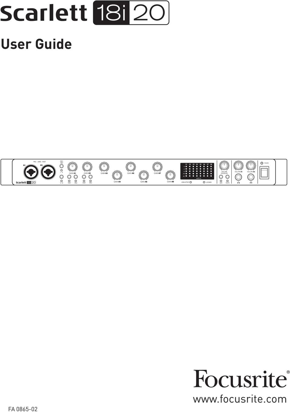
9 HARDWARE FEATURES Front Panel The front panel includes all the input gain and monitoring controls as well as two of the input connectors for Mic, Line and Instrument signals. 1. MIC-LINE-INST 01 & 02 Neutrik Combo input sockets - connect microphones, instruments (e.g., guitar), or line level signals via XLR or ¼ (6.35 mm) jacks as appropriate. Either ¼ TRS (balanced) or TS (unbalanced) jack plugs can be used for instruments or line level signals. 2. MIC 48V two switches enabling 48 V phantom power at the XLR contacts of the Combo connectors for mic inputs 1-4 and 5-8 respectively. (Note that inputs 3 to 8 are on the rear panel.) The switches each have an associated red LED indicating that phantom power is selected. 3. GAIN 01 and GAIN 02 - adjust the input gain for the signals at Inputs 1 and 2 respectively. 4. INST two switches changing the input configuration for the jack contacts at inputs 1 and 2. When INST is selected, the gain range and input impedance are altered (relative to LINE), and the input is made unbalanced. This optimises it for the direct connection of instruments (usually via a 2-pole (TS) jack plug). When INST is off, the inputs are suitable for the connection of line level signals. Line level signals may be connected either in balanced form via a 3-pole (TRS) jack or unbalanced, via a 2-pole (TS) jack. The switches each have an associated red LED indicating that INST is selected. 5. PAD two switches which insert a 10 db pad in the signal paths of Inputs 1 and 2. With the pad applied, the maximum input signal level is +16 dbu. The switches each have an associated red LED indicating that PAD is selected. 6. GAIN 03 to GAIN 08 adjust the input gain for the signals at Inputs 3 to 8 respectively. (Note that inputs 3 to 8 are on the rear panel.) 7. Input meters eight 5-segment LED bargraph meters indicating the signal levels of the eight analogue input signals. The meters show signal level after the input gain stage, and thus their indication is affected by the gain controls. The LEDs illuminate at -42 (green, signal present ), -18 (green), -6 (green), -3 (yellow) and 0 dbfs (red). A level of 0 dbfs implies digital clipping, and should always be avoided. 8. USB ACTIVE a green LED which illuminates when the unit is recognised by the computer to which it is connected. 9. LOCKED a green LED which confirms word clock synchronisation, either to the Scarlett s 18i20 s internal clock or to an external digital input. 10. VOLUME MONITOR - main monitor output level control this control will normally control 9

10 the level at the main monitor outputs on the rear panel, but can be configured in Scarlett MixControl to adjust the level at any of the unit s ten analogue outputs. 11. DIM and MUTE two switches controlling the 18i20 s monitor outputs; DIM reduces the output levels by 18 db, while MUTE turns the outputs off. By default, these switches affect the main monitor outputs 1 and 2, but may be configured in Scarlett MixControl to act on any of the analogue outputs. The switches each have an associated LED (DIM: yellow, MUTE: red) indicating that the function is selected. 12. VOLUME 01 and VOLUME 02 connect one or two pairs of stereo headphones at the two ¼ (6.25 mm) TRS jack sockets below the controls. The headphone outputs always carry the signals that currently routed to analogue outputs 7/8 and 9/10 (as stereo pairs) in Scarlett MixControl. 13. POWER - AC power switch and LED. 14. Rack ears for mounting the Scarlett 18i20 in a standard 19 equipment rack. 10
 indicating that the function is selected. 12. VOLUME 01 and VOLUME 02 connect one or two pairs of stereo headphones at the two ¼ (6.")
11 Rear Panel MIC/LINE INPUTS 3 to 8 - Neutrik Combo input sockets - connect further microphones or line level signals via XLR or ¼ (6.35 mm) jacks as appropriate. Either ¼ TRS (balanced) or TS (unbalanced) jack plugs can be used for line level signals. 2. LINE OUTPUTS 3 to 10 eight balanced analogue line outputs on ¼ (6.35 mm) jack sockets; use TRS jacks for a balanced connection or TS jacks for unbalanced. The signals available at these outputs are defined in Scarlett MixControl, and can typically be used for driving alternative speakers (i.e., midfield, nearfield, etc.), the additional speakers in a multichannel monitoring system, or to drive outboard FX processors. 3. MONITOR 1 and 2 two balanced analogue line outputs on ¼ (6.35 mm) jack sockets; use TRS jacks for a balanced connection or TS jacks for unbalanced. These are also Line Outputs 1 and 2 of the system, and will generally be used for driving the main L and R speakers of your monitoring system. However, the signals at the outputs may be defined in Scarlett MixControl. 4. OPTICAL IN and OUT two TOSLINK connectors, each carrying eight channels of digital audio in ADAT format at 44.1/48 khz sample rate or four channels at 88.2/96 khz. These are simply additional inputs and outputs (respectively) to/from the Scarlett 18i WORD CLOCK OUT a BNC connector carrying the Scarlett 18i20 s word clock; this may be used to synchronise other digital audio equipment forming part of the recording system. The source of sample clock synchronisation used by the Scarlett 18i20 is selected in Scarlett MixControl. 6. USB 2.0 port Type B connector; connect the Scarlett 18i20 to your computer with the cable supplied. 7. MIDI IN and MIDI OUT standard 5-pin DIN sockets for connection of external MIDI equipment. The Scarlett 18i20 acts as a Break-out (and Break-in) Box, allowing MIDI data to/from your computer to be distributed to additional MIDI devices. 8. SPDIF IN and OUT two phono (RCA) sockets carrying two-channel digital audio signals in or out of the Scarlett 18i20 in S/PDIF format. Like all the other inputs and outputs, signals at these connectors may be routed in Scarlett MixControl. 9. AC mains standard IEC receptacle. 11

12 Connecting your Scarlett 18i20 IMPORTANT: Before you connect the Scarlett 18i20 to your computer, please complete the software installation according to the instructions on page 8. This will ensure that the hardware uses the correct drivers, and will prevent unexpected behaviour. The Scarlett 18i20 should be connected to AC mains with the supplied AC power cable. Plug the IEC connector into the rear panel IEC receptacle and turn the unit on with the front panel power switch. The Scarlett 18i20 has a single USB 2.0 port (on the rear panel). Once the software installation is complete, simply connect the Scarlett 18i20 to your computer using the USB cable provided. (Note that Scarlett 18i20 is a USB 2.0 device, and thus the USB connection requires a USB 2.0-compliant port on your computer. It will not operate correctly with USB 1.0/1.1 ports.) Mac OS only: Your OS should automatically switch the computer s default audio connections to be the USB port to which the Scarlett 18i20 is connected. To verify this, go to System Preferences > Sound, and check that the active input and output are set to Scarlett 18i20. For more detailed setup options on a Mac, open Applications > Utilities > Audio MIDI Setup. Windows only: Your OS should automatically switch the computer s default audio connections to be the USB port to which the Scarlett 18i20 is connected. To verify this: on Windows 7 - go to Start > Control Panel > Hardware and Sound > Sound > Manage Audio Devices and ensure that Default Playback and Recording are set to Scarlett 18i20. on Windows 8, navigate to Control Panel and then select Hardware and Sound > Sound > Manage Audio Devices and ensure that Default Playback and Recording are set to Scarlett 18i20. Audio Setup in your DAW The Scarlett 18i20 is compatible with any Windows-based DAW that supports ASIO or WDM* or any Mac-based DAW that uses Core Audio. After installing the drivers and connecting the hardware, you can start using the Scarlett 18i20 with the DAW of your choice. To allow you to get started if you do not already have a DAW application installed on your computer, Ableton Live Lite is included; this will be available to you once you ve downloaded and activated your software on-line. To install Ableton Live Lite, download and save the Ableton installer file from your registered Focusrite My Products page as described above, and then run it, following all on-screen instructions. Operating instructions for Ableton Live Lite are beyond the scope of this User Guide, but the application includes a full set of Help files. *only compatible with 16-bit audio under WDM 12

13 Please note - your DAW may not automatically select the Scarlett 18i20 as its default I/O device. In this case, you must manually select the driver on your DAW s Audio Setup* page (select Scarlett 18i20 driver for Mac or Focusrite USB 2.0 driver for Windows). Please refer to your DAW s documentation (or Help files) if you are unsure where to select the ASIO/ Core Audio driver. The example below shows the correct configuration in the Ableton Live Lite Preferences panel (Mac version shown). Once the Scarlett 18i20 is set as the preferred Audio Device* in your DAW, all the inputs and outputs will appear in your DAW s Audio I/O preferences. Depending on your DAW, you may need to enable certain inputs or outputs before use. The two examples below show two inputs and two outputs enabled in the Ableton Lite Audio Preferences. *Typical name. Terminology may differ slightly between DAWs. 13
.")
14 25SL MkII Example of Usage The Scarlett 18i20 is an excellent choice for numerous recording and monitoring applications. Some typical configurations are shown below. 1. Recording a band Microphone Guitar Engineers Headphones (Front Panel) (Rear Panel) DI Box DI Box Stereo Keys Musicians Individual feedback mixes This setup illustrates a typical configuration for multitrack recording with DAW software on your Mac or PC. A selection of sources microphones, a guitar and DI boxes are shown connected to the Scarlett 18i20 s inputs. Note that only Inputs 1 and 2 can be configured to accept instruments directly, so we have chosen to plug the guitar into Input 2. Ensure the INST button is pressed and the INST LED is illuminated. The connection to the PC or Mac running DAW software is via the USB cable supplied. This will carry all the input and output signals between the DAW and the Scarlett 18i20. Once the audio setup is correctly configured in the DAW, each input source will be automatically routed to its own DAW track for recording. 14

15 25SL MkII Using Direct Monitoring You will frequently hear the term latency used in connection with digital audio systems. In the case of the simple DAW recording application described above, latency will be the time it takes for your input signals to pass through your computer and audio software. Latency can be a problem for a performer who wishes to record while monitoring their input signals. The Scarlett 18i20, in conjunction with Scarlett MixControl, allows Direct Monitoring, which overcomes this problem. You can route your input signals directly to the Scarlett 18i20 s headphone and line outputs. This enables the musicians to hear themselves with ultra-low latency i.e., effectively in real time along with the computer playback. The input signals to the computer are not affected in any way by this setting. In the example, each of the band members is receiving his/her own monitor mix, because they each have their own Scarlett 18i20 output. Scarlett MixControl lets you define up to eight separate mixes, and these mixes may include previously recorded DAW tracks as well the current input signals. Guitar Bass Headphones (Guitar) Headphones (Bass) Headphones (Keyboards) Headphones (Drums) Headphones (Vocals) Direct Monitoring set up in Mix Control Software Line to Headphone Converter Line to Headphone Converter Line to Headphone Converter Keyboards Kick Snare Overheads Vocals When using Direct Monitoring, ensure that your DAW software is not set to route any inputs (what you are currently recording) to any outputs. If it is, the musicians will hear themselves twice, with one signal audibly delayed as an echo. 15

16 2. Connecting Scarlett 18i20 to loudspeakers The 1/4 jack MONITOR outputs on the rear panel (Line Outputs 1 and 2) will normally be used to drive monitoring speakers. Self-powered monitors (e.g., typical computer speakers) incorporate internal amplifiers, and may be connected directly. Passive loudspeakers will require a separate stereo amplifier; in this case, the rear panel outputs should be connected to the amplifier s inputs. All the line output connectors are 3-pole (TRS) ¼ (6.35 mm) jack sockets, and are electronically balanced. Typical consumer (hi-fi) amplifiers and small powered monitors will have unbalanced inputs, either on phono (RCA) sockets, or via a 3.5 mm 3-pole jack plug intended for direct connection to a computer. In either case, use a suitable connecting cable with jack plugs at one end. Professional power amplifiers will generally have balanced inputs. When mixing, you can connect several pairs of additional speakers (mid-field. near-field, etc.) to pairs of outputs and use Scarlett MixControl to route your mix to the different outputs as desired, to check your mix on the different types of speaker. 16

17 Working with surround sound Because the Scarlett 18i20 is equipped with ten line outputs, it is ideally suited for use when working in multichannel sound formats LCRS, 5.1 surround or 7.1 surround, for example. Scarlett MixControl s Monitor section is pre-configured for several multichannel formats, and resetting the monitor routing can be achieved with a few mouse clicks. The example below shows how you would connect the six loudspeakers in a 5.1 surround monitoring arrangement. Left (L) Centre (C) Right (R) (Sub Bass) LFE Rear Left (RL) Note - Amplifiers not shown Rear Right (RR) The table below summarises how some common multichannel formats are mapped to the Scarlett 18i20 s outputs: FORMAT OUT 1 OUT 2 OUT 3 OUT 4 OUT 5 OUT 6 OUT 7 OUT 8 Quad L R RL RR 2.1 L R LFE 5.1 L R C LFE RL RR 7.1 L R C LFE SL SR RL RR RL/RR = Rear Left/Rear Right;; SL/SR = Side Left/Side Right;; LFE = sub-bass channel 17
 Centre (C) Right (R) (Sub Bass) LFE 1 4 3 2 8 7 Rear Left (RL) Note - Amplifiers not shown Rear Right (RR) The table below summarises how some common multichannel formats are mapped to the")
18 3. Using the ADAT connections In addition to the eight analogue inputs, the Scarlett 18i20 has an optical ADAT input port which can provide an additional eight audio inputs at 44.1/48 khz sample rate or four at 88.2/96 khz. Using a separate 8-channel microphone preamplifier equipped with an ADAT output such as the Focusrite OctoPre MkII provides a simple and excellent method of expanding the Scarlett 18i20 s input capability. Inputs 1 & 2 on front panel Octopre 8ch Mic Amp Computer running DAW and Scarlett Mix Control Wordclock link Inputs 1 & 2 on front panel Optical ADAT connection (TOSLINK) Up to 16 Mic/Line Sources The OctoPre MkII s ADAT output is connected to the Scarlett 18i20 s ADAT input with a single TOSLINK optical cable. Stable word clock synchronisation may be achieved by connecting the Scarlett 18i20 s WORD CLOCK OUT to the OctoPre MKII s WORD CLOCK IN and setting the OctoPre MkII to use this as its sync source; alternatively, the Scarlett 18i20 may be set (in Scarlett MixControl) to synchronise via Channel 1 of the incoming ADAT bitstream. TIP: when interconnecting two digital devices by any method, always ensure that both are set to use the same sample rate. The additional inputs realised by use of the ADAT port may be routed using Scarlett MixControl in exactly the same manner as the other inputs. The additional inputs can form part of any musician s headphone mix, as required. If a suitable ADAT break-out box is available, the ADAT output port may be used in the opposite manner; for example, additional outputs from the DAW may be converted into the analogue domain to allow the use of an external hardware mixing console to mix down a large number of DAW tracks. 18

19 25SL MkII 4. Using the Scarlett 18i20 as a stand-alone mixer The Scarlett 18i20 has the ability to store a mix configuration defined in Scarlett MixControl within the hardware. This feature lets you configure it for example, as an on-stage keyboard mixer using your computer, and then upload the configuration to the device itself. Then you can use the Scarlett 18i20 as a simple, rack-mounting mixer as part of your keyboard rig to control the overall mix of multiple keyboards. To FOH Mixer In the example illustrated, three stereo keyboards are connected to the rear panel inputs of the Scarlett 18i20; Outputs 3 and 4 go to the main PA system. The performer can adjust the volume of the individual keyboards from the front panel; he/she can also adjust the overall level of the keyboard mix. 19

20 Scarlett MixControl Scarlett MixControl software allows flexible mixing and routing of all audio signals to the physical audio outputs, as well as control of output monitor levels. All sample rate selection, digital syncing and buffer size settings (Windows only) are available from Scarlett MixControl. Note: Scarlett MixControl is a generic product, and may be used with other hardware interfaces in the Focusrite Scarlett range. When you connect a Scarlett interface to your computer and launch Scarlett MixControl, the model of interface is automatically detected, and the software configured to suit the number of inputs and outputs, and other facilities, available on the hardware. To open Scarlett MixControl: On a Windows PC: Go to Start > Programs > Focusrite > Scarlett MixControl. On a Mac: Open Finder > Applications > Scarlett MixControl. The Scarlett MixControl GUI (Graphical User Interface) will appear as shown below (Mac version illustrated). Mixer Mixer Tab Mixer Input Channel Mixer Output Channel Monitor Section Routing Section Device Status Section 20

21 Mixer Scarlett MixControl lets you create up to mono or stereo mixes, each of which may have up to 18 input channels. A combination of mono and stereo mixes, up to the maximum of mono-equivalent, is also permissible. Each mix may be formed from any of the 18 of the Scarlett 18i20 s inputs and/or any of the 20 DAW outputs, and each mix may be sent to any number of outputs. All mixer controls are independent for each mix. The Mixer Section is used to create mixes for monitoring and foldback purposes. The mixes you create do not affect how the audio inputs are routed to the DAW, nor does it affect the audio level of the signal to be recorded. How you set up the mixer section only affects what is sent to the audio outputs. The levels of the input signals sent to the DAW for recording are adjusted on the Scarlett 18i20 using the GAIN controls. An example of use for the mixer is recording multiple musicians simultaneously, e.g., a guitarist and a vocalist performing at the same time. To record them successfully, you need to provide them with a previously-recorded backing track, and a feed of each other s input signal. The guitarist will need to hear the backing track and his/her guitar mixed prominently, plus some vocals. The vocalist will need to hear the backing track, lots of his/her own vocals, plus a little of the guitar. You can create a separate mix for each performer with the exact mix and level that he/she needs. Each musician will have his/her own mix created using a different mixer tab. Mixer Tab There are Mixer Tabs, one for each mono mix. 21
22 Input Channel Two mixer input channels are shown below. The controls available on the input channels are as follows: Audio source select This is the button at the top of the channel strip; when no source is selected to the channel, it will display Off. Clicking the button offers two lists: Inputs and DAW; selecting Inputs opens a list of all the available Scarlett 18i20 inputs, and selecting DAW opens a list of all the available DAW outputs. Any input not available is greyed-out (e.g., analogue inputs 2 to 8 are already assigned elsewhere in the example shown). Note that channels may be mono, or in pairs for stereo operation. Stereo operation borrows a adjacent channel and lets you control both left and right legs of the stereo signal with a single fader. See Stereo on page 24 for details of mono/stereo channel definition. Note that an input can only be assigned to one channel in each mix. If it has already been assigned, it will be greyed-out on other channels. computer application are routed. To include previously-recorded DAW tracks, or audio from other computer applications into the mix, select the two relevant DAW inputs as a stereo input track. These may typically be DAW 1 and DAW 2, but this will depend how the outputs of the DAW or other 22
23 Input Channel Pan Control Pan Control Fader Fader Meter Meter Stereo PFL PFL Mute Solo Channel Name Mute Solo Pan Control If the mix has been defined as a stereo one (see Output Channel on page 25), the Pan control (in the form of a slider) positions the channel signal in the stereo image, i.e., the signal is faded between two audio outputs such as monitor L and R. In the case of a stereo channel, setting the Pan control fully left mutes the right channel, and viceversa. Fader Click the fader knob and slide it to set the level of the channel signal in the mix. Double-clicking the fader knob sets the channel gain to 0 db. Note that the channel gain range is from - (muted) to +6 db; the current fader level is displayed numerically below the fader. Meter Each fader has a bargraph-style channel meter immediately to its right. The meter shows the level of the channel s input signal. The maximum instantaneous level reached is displayed numerically in the box below, and clicking anywhere on the meter will reset the value. Note that the meter s source is pre-fade the meter always shows the level of the signal at the channel input, regardless of the fader setting. 23
24 Clip light The meter is colour coded; if the red portion at the top illuminates, the signal level is too high and digital clipping may occur. This can sound very unpleasant and should be avoided at all times! You will need to reduce the signal level either at source in the case of DAW tracks or external digital inputs, or by adjusting the GAIN controls on the Scarlett 18i20 in the case of the analogue inputs. The red clip light remains illuminated once it has been triggered by excessive signal level; when the signal level has been reduced, click on the red area to reset it. Mute Clicking this button mutes the channel; it illuminates red when Mute is active. Solo Clicking this button solos the signal; all other channels in the current mix are muted. The channel fader remains active. The button illuminates yellow when Solo is active. PFL (Pre-fade listen) Clicking this button performs a non-destructive solo; the signal in the channel is routed to the main Monitor Outputs 1 and 2. The soloed signal is pre-fade (i.e., its level will not be affected by the fader). PFL is purely a monitoring function and all other channels remain active with all signals still routed. The button illuminates green when PFL is active. Stereo You can use this button to create a stereo channel from two consecutive mono channels (odd = L, even = R). Note that the mixer channel graphics alter; a single fader controls the stereo signal, but the meter has separate L and R bargraph displays. Channel Name Each mixer channel may be named; by default, the names are the channel numbers. Double click the name to rename the channel to something more useful such as Vocal Mic. 24
25 Output Channel All the input channels are mixed together and routed to the output channel of the mixer. The output channel lets you control the overall level of the entire mix. (Remember there is a separate output channel for each.) An output channel is mono by default; stereo operation may be selected by clicking its Stereo button. When the output channel is stereo, you will note that the tab for the mix doubles in size. This is because the stereo version takes up 2 channels of the available total output channel count. An output channel s fader, meter, Mute and Solo buttons operate in the same manner as for an input channel. Note that the solo button is non-latching and routes the entire mix to Monitor outputs 1 and 2. The output routing is selected by clicking on the Sel button at the top of the channel strip, which opens a drop-down list of all the available hardware outputs. You can route the mix to any or all of the Scarlett 18i20 s hardware outputs; if just one output is selected, its name is displayed at the top of the output channel. The text Many will be displayed if multiple outputs are selected. The mix may be named; by default the name is Mix n. Click in the text field below the output channel and enter a more helpful name e.g., Monitor Mix, or the name of the performer who is receiving the mix as his/her foldback feed. The name also appears on the mix tab. You may copy an existing mix to another mix. This copies all the fader/pan/mute/solo settings and channel names. To do this, click on the Copy Mix To... button and select the mix (from the list presented) which you would like to duplicate the current one. Note that you can only copy a mono mix to another mono mix, and a stereo mix to another stereo mix. Therefore you must make sure that you have correctly set up the output channels before copying the mix. 25
26 Routing Section The routing section is where you to determine how the various audio sources available in both Scarlett 18i20 and Scarlett MixControl are to be routed to the Scarlett 18i20 s physical outputs. Every physical output on the Scarlett 18i20 is listed, and the audio signal to be sent to that output may be selected from the drop-down menu which appears when the button to the left of that output is clicked. Available sources include: Any input signal Any DAW playback track Any of the mixes from the mixer section* *Note: if you have already named a mix (see previous section), then this name is displayed as the mix source name. Note that the routing section also reflects any destination selections already made for the output channels in the mixer (see previous section). If you pre-assigned outputs when you created your mix, you will see that these assignments are already displayed in the routing section. This works both ways: if you change the audio source from the routing section, the mixer output channel will display the change automatically. 26
27 Remember that the signal available at the front panel Headphones 1 output jack will always be the signal currently routed to Line Outputs 7 and 8. The Headphones 2 output follows Line Outputs 9 and 10 in a similar manner. Note: ADAT SMUX - When working at sample rates of 88.2 khz or 96 khz, the total number of ADAT channels available drops from eight (at 44.1/48 khz) to four. At these sample rates, ADAT channels 5-8 are greyed out. Routing Presets As Scarlett MixControl permits such great flexibility in routing possibilities, Routing Presets are provided to help you with making your routing and mixer set-ups. Using Presets enables you to set up your routing quickly for recording (monitoring your inputs); mixing (sending signals out to outboard processors or external mixer). Clicking the Routing Preset button opens a list from which a further selection may be made; each of the options is described below. Clear Clicking Clear deselects all output routing. This is useful for resetting all routing when starting a new task; it saves you from having to manually turn everything off first. DAW Tracking DAW Tracking is intended to be used for the initial recording process. It automatically routes DAW Tracks 1 and 2 to all Line Outputs as odd-even pairs; this includes the main Monitor Outputs (1 and 2) and the front panel Headphone Outputs 1 and 2. All the input channels must be monitored from within the DAW application. Zero Latency Tracking The Zero Latency Tracking option can be used during the recording process. It routes the outputs of Mix 1 and Mix 2 to all your Line Outputs simultaneously as odd-even pairs; this includes the main Monitor Outputs (1 and 2) and the front panel Headphone Outputs 1 and 2. Line Inputs and DAW outputs must be set up in Mix 1(if stereo, or Mixes 1 and 2 if mono) so that you are can monitor these sources with ultra-low latency. You should ensure that you are not monitoring the same signals within your DAW at the same time, otherwise you will hear the signal twice (once direct from Scarlett MixControl and a second time delayed - because of latency - from your DAW.) 27
28 TIP: If you are using a stereo mix, the left output channel will be routed to all odd-numbered outputs and the right channel to all even-numbered outputs. With mono mixes, odd-numbered mixes go to odd-numbered outputs and even-numbered mixes to even-numbered outputs. Mixing The Mixing preset can be used during the mixing stage. DAW tracks are routed to the line output of the same number, e.g., DAW tracks 1-10 are routed to Monitor Outputs 1-2 and Line outputs 3-10 respectively. In the same manner, DAW tracks are routed to the ADAT output connector and tracks 19 and 20 to the S/PDIF output as a stereo pair. Thus all 20 tracks are simultaneously available as physical outputs, if required. Monitor Section The signal levels at the monitor outputs and line outputs are adjusted in Scarlett MixControl s Monitor Section. You can configure the hardware and software so that the VOLUME MONITOR control on the front panel will set the overall monitoring volume via the desired outputs, such as your stereo monitors or your surround sound system. Alternatively, the VOLUME MONITOR control can be disabled for specific outputs; e.g., when you are using some of the outputs as sends to external processors (such as a compressor), you want the front panel control to adjust only the level at the outputs which are being used for monitoring purposes. Additional monitor functions such as mute, dim and mono are also provided. 28
29 Monitor control enable buttons (1 to 10) These buttons select which line outputs of the Scarlett 18i20 are affected by the other GUI monitor section controls, and also the front panel monitor controls. Depending on your monitoring set-up, you can control no speakers, just a single pair of speakers, or up to 10 speakers simultaneously. Note: the levels at all the digital outputs on the Scarlett 18i20 are unaffected by Scarlett MixControl s monitor section controls. If you need to route individual DAW tracks to digital outputs, adjust the output levels from the DAW. The ten buttons determine the control status of the ten line outputs. There are three states; clicking on the buttons toggles between blue and red states; clicking while holding SHIFT down puts them in the grey state. When the button is blue, the level of the line output is controlled by the GUI monitor section. When the button is red, - the line output is muted. When the button is grey, the level at the line output is fixed at full volume and is not controlled by the GUI monitor section. WARNING: The grey state should be selected when a line output is to be used to drive external processors. Note that in this state, the signal routed to that output will be at full level. Should you have amplifiers/loudspeakers connected to the output, this may result in a very high sound level in your monitor speakers or headphones. Always check your levels (in your DAW or the Scarlett MixControl Mixer) before setting the monitor button to this mode. 29
30 Monitor Presets dropdown menu A range of preset monitoring configurations is provided; click on the Monitor Preset button to open a drop-down list. These presets allow simple selection of common monitoring configurations. For the monitor presets to work correctly, you must have your speakers connected to the line outputs as shown in the table on page 17. The Monitor Presets function as follows: Off all monitor control buttons disabled; all analogue outputs are off. Mono only Line Output 3 is enabled. Connect to a centrally-located speaker for working in mono. Stereo Line Outputs 1 and 2 (Monitor 1 and 2) are enabled. All other channels are muted. Connect Output 1 to your left monitor and 2 to your right. Quad Line Outputs 1, 2, 7 and 8 are enabled. All other channels are muted. Connect Outputs 1 and 2 as for stereo; Output 7 to Rear Left and 8 to Rear Right. 2.1 Surround Line Outputs 1, 2 and 4 are enabled. All other channels are muted. Connect Outputs 1 and 2 as for stereo, and Output 4 to your sub-bass (LFE) speaker. 5.1 Surround Line Outputs 1, 2, 3, 4, 7 and 8 are enabled; Outputs 5 and 6 are muted. Connect Outputs 1 and 2 as for stereo; Output 3 is the C channel, Outputs 7 and 8 are Left and Right Surround respectively, and Output 4 is the sub-bass (LFE) channel. 7.1 Surround Outputs 1 to 8 are enabled and Outputs 9 and 10 are muted. Connect as for 5.1 Surround, adding Left Side speakers to Output 5 and Right Side to Output 6. Mid + Phones 1 for use with multiple pairs of stereo monitors; connect a pair of midrange monitors to Outputs 7 and 8. Mini + Phones 2 as above; connect a pair of near-field monitors to Outputs 9 and 10. Monitor Section Controls The controls in Scarlett MixControl s Monitor section will affect those channels that have been selected for monitor control (i.e., those displaying blue status - see above). 30
31 Monitor level control knob Set the output level of all selected outputs with this control, using the mouse. The numeric display below shows the current monitor output level. Hardware control button Clicking this button transfers control of overall monitoring level between the Scarlett MixControl and the Scarlett 18i20 s front panel VOLUME MONITOR control. When enabled, the button shows blue and the on-screen knob is disabled. Note: if the hardware control position does not match the software control position as the H/W Control button is switched in and out, the volume knob works in pick-up mode. A volume change will only occur when the position of the hardware knob matches or passes through the position commanded by the software control. This will ensure that there are no sudden unwanted volume increases when the knob is moved. Dim Mute Left Mute switch Right Mute switch Mono switch Attenuates the monitor output level by 18 db. Mutes all monitor outputs. Mutes all odd-numbered outputs. Mutes all even-numbered outputs. Sums (combines) the odd- and even-numbered output signals in pairs (i.e., 1+2, 3+4, etc.). The summed signals are then sent to both outputs of each pair. NOTE: Remember that the monitor functions above only affect the outputs that have been selected for control in the monitor control section (i.e., outputs showing blue status). 31
32 20 db Pad If using active (powered) monitors for your primary monitoring, you may find that normal listening levels require the monitor volume knob to be set quite low. In this case, click the -20 db Pad button to reduce the level at Line Outputs 1 and 2 (Monitor Outputs 1 and 2) by this amount. This will allow the Volume knob to operate over a wider range. Device Status section The Device Status section displays information about the sample rate, synchronisation and driver status of the Scarlett 18i20. The sample rate and sync source can also be set here. Sample Rate display This displays the sample rate currently in use by the Scarlett 18i20. To change the sample rate, click on the red displayed value and select 44.1 khz, 48 khz, 88.2 khz, or 96 khz from the list. Note: it is advisable to quit your DAW application BEFORE you make sample rate changes to prevent any undesirable (and audible) side-effects! Sync Source display Displays the currently selected sync source. To change the sync source, click on the red sync source text and select from the list: Internal the Scarlett 18i20 uses its own internal generator for word clock ADAT the word clock source Is derived from the signal at the ADAT input S/PDIF word clock is derived from the signal at the S/PDIF input Sync Status display Displays Locked when the Scarlett 18i20 has successfully locked to the specified Sync Source. If No Lock is displayed, the unit cannot lock to an external synchronisation source. If this occurs, please check that the cables are properly connected, and that the external digital devices have been set up as master devices and have been set to the same sample rate as the Scarlett 18i20. USB Driver This should display Connected at all times when the Scarlett 18i20 is connected to the computer via 32
33 USB. If Disconnected is displayed, please check the USB connections and that the unit is switched on. If it continues to show Disconnected, restart the computer and re-launch Scarlett MixControl. Settings Menu The Settings... button is only available on the Windows version of Scarlett MixControl. It allows you set the size of the ASIO buffer. This option lets you set the buffer size of your ASIO driver. A small buffer size will in result in lower latency, but at the expense of increased CPU usage. A high buffer size will result in higher latency, but lower CPU usage. If you are using lots of virtual instruments and effects processing in your DAW project, and the CPU usage is high, then increase the buffer size. 33
34 File Menu The File menus differ slightly between Mac and Windows versions of Scarlett MixControl. Open - opens a File Open dialogue box, allowing selection of any previously saved Scarlett MixControl mix data. Save - opens a File Save dialogue box, allowing selection of a location to which your Scarlett MixControl mix data can be saved. Subsequent Saves overwrite the original file. Save As - opens a File Save As dialogue box. Use this option if you want to keep your original saved mix data but save the current mix data under a different filename. Restore Factory Default - resets the Scarlett 18i20 to its original default factory state. This can be used to globally reset all mixer, routing, and monitor settings, allowing creation of a new set-up from scratch. Save to Hardware - This saves the current Scarlett MixControl set-up to the Scarlett 18i20 hardware. If you are moving the Scarlett 18i20 from one computer to another and want to retain the set-up, or want to use it in stand-alone mode, select this option. Note that Scarlett MixControl does not automatically load from hardware (as this would overwrite a current set-up). As with nearly all other software applications, Open, Save and Save As all have standard keyboard shortcuts. 34
35 Scarlett 18i20 Performance Specifications Configuration Inputs 18: analogue (8), S/PDIF (2), ADAT (8) Outputs 20: analogue (10), S/PDIF (2), ADAT (8) Mixer Fully assignable 18-in/16-out mixer Digital Performance A-D Dynamic Range D-A Dynamic Range Supported sample rates Clock jitter 105 db CCIR-RMS (all inputs) 103 db CCIR-RMS (line outputs) 44.1 khz, 48 khz, 88.2 khz & 96 khz <250 ps Microphone Inputs Frequency Response THD+N Noise EIN Maximum input level 20 Hz ± 0.5 db, 20 khz ± 0.1 db (min. gain) 0.001% (1 khz, 1dBFS, 20 khz BW) 122 dbu CCIR-RMS (measured at 60 db of gain with 150 ohm termination) +8 dbu (without pad) Line Inputs Frequency Response THD+N Noise (NiPoS) Maximum input level 20 Hz 20 khz ± 0.1 db 0.007% (1 khz, 1dBFS, 20 khz BW) 105 dbfs CCIR-RMS (measured at min. gain with 50 ohm termination) +28 dbu Instrument Inputs Frequency Response THD+N Noise (NiPoS) Maximum input level 20 Hz 20 khz ± 0.1 db 0.007% (1 khz, 1dBFS, 20 khz BW) 103 dbfs CCIR-RMS (measured at min. gain) +8 db (without pad) Line Outputs 1 & 2 Maximum Output Level (0 dbfs) THD+N +16 dbu, balanced 0.001% (1 khz, 1dBFS, 20 khz BW) 35
36 Physical and Electrical Characteristics Analogue Inputs Inputs 1 & 2 Connectors Mic/Line switching Line/Instrument switching Phantom power Neutrik XLR Combo: Mic/Line/Inst, on front panel Automatic 2 x front panel switches Shared +48 V phantom power switch for inputs 1 to 4 Analogue Inputs 3 to 8 Connectors Mic/Line switching Phantom power Neutrik XLR Combo: Mic/Line, on rear panel Automatic Shared +48 V phantom power switch for inputs 1 to 4 and 5 to 8 Analogue Outputs Main outputs Stereo headphone outputs Main monitor output level control Headphones level controls 10 x balanced ¼ TRS jacks (on rear panel) 2 x ¼ TRS jack on front panel On front panel Other I/O ADAT I/O 2 x TOSLINK optical connectors; /48 khz S/PDIF I/O 2 x phono (RCA); can be re-assigned to ADAT ports in software Word clock output USB MIDI I/O BNC connector 1 x USB 2.0 Type B connector 2 x 5-pin DIN sockets Weight and Dimensions W x D x H Weight 482 mm x 265 mm x 45 mm (1U) 3 kg 36
37 Troubleshooting For all troubleshooting queries, please visit the Focusrite Answerbase at where you will find articles covering numerous troubleshooting examples. COPYRIGHT AND LEGAL NOTICES Focusrite is a registered trade mark and Scarlett 18i20 is a trade mark of Focusrite Audio Engineering Limited. All other trade marks and trade names are the property of their respective owners Focusrite Audio Engineering Limited. All rights reserved. 37
User Guide FFFA001106. www.focusrite.com
 User Guide FFFA001106 www.focusrite.com TABLE OF CONTENTS OVERVIEW.... 3 Introduction...3 Features.................................................................... 3 Box Contents...3 System Requirements....4
Focusrite Saffire 6 USB. User Guide
 Focusrite Saffire 6 USB User Guide 1 IMPORTANT SAFETY INSTRUCTIONS 1. Read these instructions. 2. Keep these instructions. 3. Heed all warnings. 4. Follow all instructions. 5. Do not use this apparatus
BIG GAMES HOME VIDEO ARCADE ASSEMBLY INSTRUCTIONS
 TM BIG GAMES HOME VIDEO ARCADE ASSEMBLY INSTRUCTIONS IN-HOME ASSEMBLY OF YOUR BIGGAMES HOME VIDEO ARCADE MAY BE AVAILABLE IN YOUR AREA FOR AN ADDITIONAL CHARGE. FOR INFORMATION, PLEASE CALL (800) 749-4345.
Evolution Digital HD Set-Top Box Important Safety Instructions
 Evolution Digital HD Set-Top Box Important Safety Instructions 1. Read these instructions. 2. Keep these instructions. 3. Heed all warnings. 4. Follow all instructions. 5. Do not use this apparatus near
CAUTION RISK OF ELECTRIC SHOCK NO NOT OPEN
 Evolution Digital HD Set-Top Box Important Safety Instructions 1. Read these instructions. 2. Keep these instructions. 3. Heed all warnings. 4. Follow all instructions. 5. Do not use this apparatus near
ATTENTION RISQUE D ÉLECTROCUTION! NE PAS OUVRIR!
 Quick Start Guide ATTENTION RISQUE D ÉLECTROCUTION! NE PAS OUVRIR! CAUTION: TO REDUCE THE RISK OF ELECTRIC SHOCK, DO NOT REMOVE COVER (OR BACK). NO USER-SERVICEABLE PARTS INSIDE. REFER SER- VICING TO QUALIFIED
IMPORTANT SAFETY INSTRUCTIONS
 IMPORTANT SAFETY INSTRUCTIONS Before you install or use the apparatus, you must read and understand these Important Safety Instructions. At all times when using the apparatus you must follow these Important
Digital Satellite Receiver
 USER GUIDE Digital Satellite Receiver Models DSR207, DSR317, DSR505, and DSR530 CONTENTS IMPORTANT SAFETY INSTRUCTIONS...1 DSR BASICS SYMBOLS/ICONS...6 Front Panel...6 Back Panel...7 CONNECTING YOUR DSR...10
Fast Track Solo Guide
 Fast Track Solo Guide Legal Notices 2013 Avid Technology, Inc., ( Avid ), all rights reserved. This guide may not be duplicated in whole or in part without the written consent of Avid. Avid, the Avid logo,
HD udta Quick-Start Guide
 HD udta Quick-Start Guide Vyve Broadband HD Set-Top Box Important Safety Instructions 1. Read these instructions. 2. Keep these instructions. 3. Heed all warnings. 4. Follow all instructions. 5. Do not
Spider IV 15. Pilot s Handbook Manuel de pilotage Pilotenhandbuch Pilotenhandboek Manual del Piloto 取 扱 説 明 書
 Spider IV 15 Pilot s Handbook Manuel de pilotage Pilotenhandbuch Pilotenhandboek Manual del Piloto 取 扱 説 明 書 40-00-0187 Pilot s Handbook available @ www.line6.com/manuals Rev D Important Safety Instructions
The Bouncer Bluetooth Stereo Speaker
 The Bouncer Bluetooth Stereo Speaker 1 Welcome to JLab! Thank you for purchasing The Bouncer Bluetooth Speaker! Enjoy your music wirelessly from any smartphone, tablet, laptop, or other Bluetooth enabled
ATTENTION RISQUE D ÉLECTROCUTION! NE PAS OUVRIR!
 Quick Start Guide ATTENTION RISQUE D ÉLECTROCUTION! NE PAS OUVRIR! CAUTION: TO REDUCE THE RISK OF ELECTRIC SHOCK, DO NOT REMOVE COVER (OR BACK). NO USER-SERVICEABLE PARTS INSIDE. REFER SER- VICING TO QUALIFIED
igroove SXT Owner's Manual
 TM igroove SXT Owner's Manual Important Safety Safety Information Information 1. READ these instructions. 2. KEEP these instructions. 3. HEED all warnings. 4. FOLLOW all instructions. 5. DO NOT use this
Power Supply Guide Version 1.0 for D-Show
 Power Supply Guide Version 1.0 for D-Show Digidesign 2001 Junipero Serra Boulevard Daly City, CA 94014-3886 USA tel: 650 731 6300 fax: 650 731 6399 Technical Support (USA) tel: 650 731 6100 fax: 650 731
2 series II COMPANION MULTIMEDIA SPEAKERS
 COMPANION MULTIMEDIA SPEAKERS Quick Setup Guide and Safety Information GuÍa rápida de instalación y información de seguridad Notice de montage et informations relatives à la sécurité 2 series II For additional
When you switch off your system, or mute the sound, the red indicator light appears immediately, indicating that the subwoofer is not in use.
 BeoLab 11 Guide WARNING: To reduce the risk of fire or electric shock, do not expose this appliance to rain or moisture. Do not expose this equip ment to dripping or splashing and ensure that no objects
Soundcraft Signature MTK Recording Guide
 Soundcraft Signature MTK Recording Guide S O U N D C R A F T S I G N AT U R E M T K R E C O R D I N G G U I D E 2 Table of Contents USB Overview... 04 Installing the Drivers (PC Only)... 04 Finding the
by HARMAN MADI-USB Combo Card User Guide
 by HARMAN MADI-USB Combo Card User Guide IMPORTANT Please read this manual carefully before using your card for the first time. This This equipment equipment complies complies with the EMC directive 2004/108/EC
User Manual DIGITAL MONITOR SPEAKERS MS /MS. 24-Bit/192 khz Digital 40/20-Watt Stereo Near Field Monitors
 User Manual DIGITAL MONITOR SPEAKERS MS /MS 24-Bit/192 khz Digital 40/20-Watt Stereo Near Field Monitors 2 DIGITAL MONITOR SPEAKERS /MS20 User Manual User Manual Table of Contents Thank you... 2 Important
PORTABLE ALARM CLOCK. Dual Alarm. FM Radio. Wake-up Sounds. USB Phone Charger G-1CR
 G-BUZZ PORTABLE ALARM CLOCK Dual Alarm FM Radio Wake-up Sounds USB Phone Charger G-1CR Welcome Alarm clocks can be boring. Get ready to shake things up with your new G-BUZZ. Slap the snooze for more ZZZ
VoiceTone T1 USER S MANUAL
 VoiceTone T1 USER S MANUAL Important Safety Instructions 1 Read these instructions. 2 Keep these instructions. 3 Heed all warnings. 4 Follow all instructions. 5 Do not use this apparatus near water. 6
User Guide FA9096-02. www.focusrite.com
 User Guide ON FA9096-02 www.focusrite.com IMPORTANT SAFETY INSTRUCTIONS 1. Read these instructions. 2. Keep these instructions. 3. Heed all warnings. 4. Follow all instructions. 5. Do not use this apparatus
USER GUIDE LOUDBOX MINI
 USER GUIDE LOUDBOX MINI Whenever this symbol appears, it alerts you to the presence of important operating and maintenance (servicing) instructions in the user s manual for this amplifier. Wherever this
SUB 10 ACTIVE STUDIO SUBWOOFER
 USER S MANUAL SUB 10 ACTIVE STUDIO SUBWOOFER CONTENTS page INTRODUCTION GENERAL INFORMATION 3 REAR PANEL REAR PANEL 4 INPUTS/OUTPUTS 4 SWITCHES 5 INDICATORS 6 TECHNICAL SPECIFICATIONS TECHNICAL SPECIFICATIONS
Model PS-4001 Power Supply User Instructions
 Model PS-4001 Power Supply User Instructions 9350-7710-000 Rev E 9/2009 PROPRIETARY NOTICE The product information and design disclosed herein were originated by and are the property of Bosch Security
Professional 24-bit USB Audio Interface. User s Guide
 Professional 24-bit USB Audio Interface User s Guide - Copyright 2016 Revision 1, January 2016 www.esi-audio.com INDEX 1. Introduction... 4 1.1 Features... 4 2. Installation... 5 2.1 System Recommendation...
BOSE. Link AL8 HOMEWIDE WIRELESS AUDIO LINK
 BOSE Link AL8 HOMEWIDE WIRELESS AUDIO LINK Français English SAFETY INFORMATION Please read this owner s guide Please take the time to follow the instructions in this owner s guide carefully. It will help
1 ULTRA-DI DI100 User Manual. User Manual ULTRA-DI DI100. Professional Battery/Phantom Powered DI-Box
 1 ULTRA-DI DI100 User Manual User Manual ULTRA-DI DI100 Professional Battery/Phantom Powered DI-Box 2 ULTRA-DI DI100 User Manual Table of Contents Thank you... 2 1. Control Elements... 7 2. DI100 Configurations...
Daily use. Never use alcohol or other solvents to clean any part of the loudspeakers!
 BeoLab 6002 Guide WARNING: To reduce the risk of fire or electric shock, do not expose this appliance to rain or moisture. Do not expose this equip ment to dripping or splashing and ensure that no objects
Mbox Basics Guide. Version 6.7 for LE Systems on Windows XP or Mac OS X. Digidesign
 Mbox Basics Guide Version 6.7 for LE Systems on Windows XP or Mac OS X Digidesign 2001 Junipero Serra Boulevard Daly City, CA 94014-3886 USA tel: 650 731 6300 fax: 650 731 6399 Technical Support (USA)
COMPANION 2 Series II MULTIMEDIA SPEAKERS
 COMPANION 2 Series II MULTIMEDIA SPEAKERS Owner s Guide Guia del usuario Notice d utilisation Français English SAFETY INFORMATION Please read this owner s guide Please take the time to follow the instructions
Important Safety Instructions
 PR-D7 GB Revision 1 Important Safety Instructions 1. Read these instructions. 2. Keep these instructions. 3. Heed all warnings. 4. Follow all instructions. 5. Do not use this apparatus near water. 6. Clean
USER GUIDE MANUAL DCT700. One-way Application
 USER GUIDE MANUAL DCT700 One-way Application CAUTION: CAUTION RISK OF ELECTRIC SHOCK TO REDUCE THE RISK OF ELECTRIC SHOCK, DO NOT REMOVE COVER (OR BACK). NO USER-SERVICEABLE PARTS INSIDE. REFER SERVICING
TABLETOP CONTROLLER USER'S MANUAL
 TABLETOP CONTROLLER USER'S MANUAL Preface TABLETOP CONTROLLER USER S MANUAL CLEARONE PART NO. 800-151-891 OCTOBER 2009 (REV. 2.1) 2009 ClearOne Communications, Inc. All rights reserved. No part of this
CAUTION RISK OF ELECTRIC SHOCK DO NOT OPEN
 BeoLab 4 Guide CAUTION RISK OF ELECTRIC SHOCK DO NOT OPEN CAUTION: To reduce the risk of electric shock, do not remove cover (or back). No User-serviceable parts inside. Refer servicing to qualified service
SDM-190M. User Guide
 SDM-190M User Guide High Resolution Stereoscopic 3D Monitor TRUE3Di CONTENTS Parts Included... 3 Button Function description... 5 Installation guide... 7 Stereoscopic driver installation guide... 17 Quadro
User Guide. MT-91 / MT-90 / MT-92 Interlinking Transmitter Module MT-90/MT-92 MT-91
 User Guide MT-9 / MT-90 / MT-9 MT-90/MT-9 All rights reserved. MN 04/08 Do not copy or forward without prior approvals MIPRO. Specifications and design subject to change without notice. CE5 0 4 A MT-9
PolyTune USER S MANUAL
 PolyTune USER S MANUAL Important Safety Instructions 1 Read these instructions. 2 Keep these instructions. 3 Heed all warnings. 4 Follow all instructions. 5 Do not use this apparatus near water. 6 Clean
XPanel V2. Remote Control Panel. User Manual. XILICA Audio Design
 XPanel V2 Remote Control Panel User Manual XILICA Audio Design Important Safety Instructions 1. READ THESE INSTRUCTIONS All the safety and operating instructions should be read before the product is operated.
Business Audio System: Music & Messaging MP3 Player. by Grace Digital Audio. User Guide. Model No. GDI-USBM10
 Business Audio System: Music & Messaging MP3 Player by Grace Digital Audio User Guide Model No. GDI-USBM10 User Guide Contents Introduction 2 Safety & General Use Information 2 Features 3 Set Up & Operation
Conference Phone UserÕs Manual. Part No. 54-2070-01R1 Printed in Korea. 2002 Bogen Communications, Inc.
 Part No. 54-2070-01R1 Printed in Korea. 2002 Bogen Communications, Inc. UserÕs Manual Notice Every effort was made to ensure that the information in this guide was complete and accurate at the time of
VIEW. SLX300 SpeakerLinX IP Zone. Amplifier Installation and Setup Guide. AVoIP
 VIEW SLX300 SpeakerLinX IP Zone Amplifier Installation and Setup Guide TM AVoIP ClearOne 5225 Wiley Post Way Suite 500 Salt Lake City, UT 84116 Telephone 1.800.283.5936 1.801.974.3760 Tech Sales 1.800.705.2103
COMPANION 20 MULTIMEDIA SPEAKER SYSTEM. Owner s Guide Guía de usuario Notice d utilisation
 COMPANION 20 MULTIMEDIA SPEAKER SYSTEM Owner s Guide Guía de usuario Notice d utilisation Safety and Regulatory Information Please read this owner s guide Please take the time to follow the instructions
QUALITY AV PRODUCTS INMATE/INMATE USB PROFESSIONAL 19" MIXER. User Guide and Reference Manual
 INMATE/INMATE USB PROFESSIONAL " MIXER User Guide and Reference Manual INTRODUCTION Welcome to the NEWHANK INMATE and INMATE USB professional " mixers series user manual. INMATE and INMATE USB both offer
User Guide USB 2.0 LAPTOP DOCKING STATION WITH VIDEO N2953
 USB 2.0 LAPTOP DOCKING STATION WITH VIDEO 410-1864-001B / ACP51US 1 YEAR LIMITED WARRANTY: We pride ourselves on the quality of our products. For complete warranty details and a list of our worldwide offices,
User guide. Stereo Bluetooth Headset SBH50
 User guide Stereo Bluetooth Headset SBH50 Contents Stereo Bluetooth Headset User guide...3 Introduction...4 Function overview...4 Hardware overview...4 Status icon overview...5 Basics...6 Charging the
Basics. Mbox 2. Version 7.0
 Basics Mbox 2 Version 7.0 Copyright 2005 Digidesign, a division of Avid Technology, Inc. All rights reserved. This guide may not be duplicated in whole or in part without the express written consent of
Funktional Technologies. Model: Chocolate Box
 Funktional Technologies Model: Chocolate Box November 2013 The Funktional Technologies Chocolate Box is a 2U analog & digital professional audio device. It incorporates two Cadac K type analog input modules.
Wave/PC Interactive System USB Adapter Kit. Installation Guide
 Wave/PC Interactive System USB Adapter Kit Installation Guide Safety Information 1. Read these instructions for all components before using this product. 2. Keep these instructions for future reference.
SoftRAID 5 QUICK START GUIDE. for OWC ThunderBay
 SoftRAID 5 QUICK START GUIDE for OWC ThunderBay TABLE OF CONTENTS INTRODUCTION...1 1.1 MINIMUM SYSTEM REQUIREMENTS 1.2 FEATURES 1.3 ABOUT THIS MANUAL SYSTEM SETUP...2 2.1 GETTING STARTED 2.2 INITIALIZING,
Message from the Development Team. Contents. Message from the Development Team..2. Panel Controls and Terminals...3. Using the UR22mkII...
 EN Contents Contents Message from the Development Team..2 Panel Controls and Terminals...3 Front Panel...3 Rear Panel...5 Software...7 Using the UR22mkII...10 Connections...10 Configuring Audio Driver
Prescott. CD Alarm Clock Radio INSTRUCTION MANUAL
 1215205 Prescott CD Alarm Clock Radio INSTRUCTION MANUAL Important Safety Instructions CAUTION RISK OF ELECTRIC SHOCK DO NOT OPEN The lightning flash with arrowhead symbol, within an equilateral triangle
MPA-101. WARNING: Improper installation could result in damage to the amplifier and/or speakers. Read all instructions before installation.
 MPA-101 WARNING: Improper installation could result in damage to the amplifier and/or speakers. Read all instructions before installation. The lightning flash with arrowhead, within an equilateral triangle,
2.0 AUDIO RECORDING INTERFACE
 24-Bit/96kHz USB 2.0 AUDIO RECORDING INTERFACE USER MANUAL 1 of 13 Contents: 1. Instruction 03 2. Key Features 03 3. Front Panel 03 4. Rear Panel 04 5. Minimum System Requirements 04 6. Installation Process
Instruction Manual. 5.1 Power Amplified Home Theatre Speaker System w/ Remote Control DSS-200
 R Instruction Manual DSS-200 R 5.1 Power Amplified Home Theatre Speaker System w/ Remote Control Read this manual carefully to get the excellent acoustics from this unit. SPECIFICATIONS SAFETY INFORMATION
DITTO LOOPER. User Manual
 DITTO LOOPER User Manual Table of contents Introduction 1 Important safety instructions 2 EMC/EMI 3 Unpacking and setting up 4 Ditto Looper in 30 seconds 5 Operation 5 Technical Specifications 5 Input,
CAUTION RISK OF ELECTRIC SHOCK DO NOT OPEN
 BeoLab 7-6 Guide CAUTION RISK OF ELECTRIC SHOCK DO NOT OPEN CAUTION: To reduce the risk of electric shock, do not remove cover (or back). No User-serviceable parts inside. Refer servicing to qualified
AM / FM Tuner + RDS. Model: TU-101. www.pulse-audio.co.uk
 AM / FM Tuner + RDS Model: TU-101 www.pulse-audio.co.uk 1 Safety Information The lightning bolt within a triangle is intended to alert the user to the presence of dangerous voltage levels within the product
Comfort Contego User Manual
 Comfort Contego User Manual Please read the User Manual before using this product. Comfort Contego T900 Transmitter English Comfort Contego R900 Receiver DO NOT USE the COMFORT CONTEGO if you have a PACEMAKER
HOME THEATER SYSTEM. Instruction Manual. Model ASR150. Please read the instruction manual carefully before using your unit.
 SURROUND SOUND HOME THEATER SYSTEM Instruction Manual Model ASR150 Please read the instruction manual carefully before using your unit. For support visit : www.1800customersupport.com GENERAL TABLE OF
User Manual CABLE TESTER CT100. Professional 6-in-1 Cable Tester
 User Manual CABLE TESTER CT100 Professional 6-in-1 Cable Tester 2 CABLE TESTER CT100 User Manual 1. Introduction Congratulations! With the CT100, you have purchased an indispensable tool that enables you
Tone Hammer 500. Owners Manual. Manual Version 1.0
 Tone Hammer 500 Owners Manual Manual Version 1.0 1. Incorporating the preamp from the popular Tone Hammer preamp/di pedal this superlight bass head combines three bands of flexible EQ, a colorful "Drive"
USER GUIDE ENGLISH ( 3 6 )
") USER GUIDE ENGLISH ( 3 6 ) GUÍA DEL USUARIO ESPAÑOL ( 7 10 ) GUIDE D'UTILISATION FRANÇAIS ( 11 14 ) GUIDA PER L'USO ITALIANO ( 15 18 ) BENUTZERHANDBUCH DEUTSCH ( 19 22 ) USER GUIDE (ENGLISH) Box Contents
USER GUIDE ENGLISH ( 3 6 ) GUÍA DEL USUARIO ESPAÑOL ( 7 10 ) GUIDE D'UTILISATION FRANÇAIS ( 11 14 ) GUIDA PER L'USO ITALIANO ( 15 18 ) BENUTZERHANDBUCH DEUTSCH ( 19 22 ) USER GUIDE (ENGLISH) Box Contents
Bluetooth Stereo Headphone. User Guide. Hive
 Bluetooth Stereo Headphone User Guide Hive 1. Product Description Avantree Hive is a Bluetooth stereo headphone with MIC from the Avantree family. It delivers clear voice transmission and high quality
HDVD 800. Pure audio in perfection. Instruction manual
 HDVD 800 Pure audio in perfection Instruction manual Contents Contents Important safety instructions... 2 The HDVD 800 headphone amplifier... 4 Package contents... 5 Product overview... 6 Overview of the
CAUTION RISK OF ELECTRIC SHOCK DO NOT OPEN
 BeoLab 4000 Guide CAUTION RISK OF ELECTRIC SHOCK DO NOT OPEN CAUTION: To reduce the risk of electric shock, do not remove cover (or back). No User-serviceable parts inside. Refer servicing to qualified
USER GUIDE ENGLISH ( 3 6 )
") USER GUIDE ENGLISH ( 3 6 ) GUÍA DEL USUARIO ESPAÑOL ( 7 10 ) GUIDE D'UTILISATION FRANÇAIS ( 11 14 ) GUIDA PER L'USO ITALIANO ( 15 18 ) BENUTZERHANDBUCH DEUTSCH ( 19 22 ) USER GUIDE (ENGLISH) Box Contents
USER GUIDE ENGLISH ( 3 6 ) GUÍA DEL USUARIO ESPAÑOL ( 7 10 ) GUIDE D'UTILISATION FRANÇAIS ( 11 14 ) GUIDA PER L'USO ITALIANO ( 15 18 ) BENUTZERHANDBUCH DEUTSCH ( 19 22 ) USER GUIDE (ENGLISH) Box Contents
Setup Guide. www.audioengineusa.com D1. Premium 24-bit DAC
 Setup Guide www.audioengineusa.com D1 24-bit DAC Premium 24-bit DAC Contents Introduction Package Contents Cleaning Features Overview Quick Setup Troubleshooting Specifications Contact Us About Audioengine
To Purchase This Item, Visit BMI Gaming www.bmigaming.com (800) 746-2255 +1.561.391.7200. Owner s Manual
 746-2255 +1.561.391.7200. Owner s Manual") Owner s Manual 4616 W. 19th Street, Cicero, IL 60804 (708) 780-0070 1 ARCADE LEGENDS 3 TM Thank you for purchasing Chicago Gaming Company s Arcade Legends 3. You can look forward to many hours of video
Owner s Manual 4616 W. 19th Street, Cicero, IL 60804 (708) 780-0070 1 ARCADE LEGENDS 3 TM Thank you for purchasing Chicago Gaming Company s Arcade Legends 3. You can look forward to many hours of video
To reduce the risk of electrical shocks, fire, and related hazards:
 Owner s Manual 1 Contents 1. Safety Notes 5 2. Introduction 6 3. Features 7 4. Installation Guide 8 5. Front Panel Explained 9 6. Rear Panel Explained 10 7. Software Control Panel 12 8. Advanced User Tips
2XWSXWFKDQQHOV 3KDVH &+ CH 2 &+ CH 4 &+ CH 6 L1 X X L2 X X L3 X X
 INSTALLATION INSTRUCTIONS ENGLISH Version 1 1 January 2004 EUROLIGHT LD6230 IMPORTANT SAFETY INSTRUCTIONS DETAILED SAFETY INSTRUCTIONS: 1) Read these instructions 2) Keep these instructions 3) Heed all
1. Introduction. 2. What s in the Box
 Table of Contents 1. Introduction.............................................................................................2 2. What s in the Box........................................................................................2
eela-audio EA916 Journalist Unit USB Audio module with Telephone Hybrid User manual
 eela-audio EA916 Journalist Unit USB Audio module with Telephone Hybrid User manual EA Broadcast / Eela Audio, Het Riet 8 A, 5431NM Cuijk, The Netherlands http://www.eela-audio.com e-mail: [email protected]
HP-1000E v2. User s Manual. Powerline Ethernet Adapter. HP1000E v2 User s Manual
 HP-1000E v2 Powerline Ethernet Adapter User s Manual HP1000E v2 User s Manual Table of Contents Chapter 1: Introduction...1 Chapter 2: Planning your Powerline Network...1 Network Topology...1 Chapter 3:
KEYBOARD EXTENDED RANGE. Sixty Owner, s Manual P/N 049254
 THE SOUND THAT CREATES LEGENDS KEYBOARD EXTENDED RANGE Sixty Owner, s Manual P/N 049254 INTRODUCTION Your new Fender KXR 60 Keyboard Amplifier is the result of Fender s ongoing dialog with many of today
Co-designed by TASCAM and
 Page 1 of 6 FW-1884 Control Surface and Audio/MIDI Interface Up to 18 simultaneous inputs Comprehensive mixing, automation, editing and navigation tools for DAWs Eight 100mm motorized touchsensitive channel
Getting Started with a blank desk...3. Understanding the Rear Panel and Top Connectors...3. Understanding the Front Panel...5
 2nd Edition Table of contents Getting Started with a blank desk...3 Understanding the Rear Panel and Top Connectors...3 Understanding the Front Panel...5 Controlling Channel Faders...6 Changing INPUT PATCH...7
Plantronics Calisto Headset with Bluetooth USB Adapter User Guide 56-K61A-23010
 56-K61A-23010 Plantronics Calisto Headset with Bluetooth USB Adapter User Guide Contents Package Contents... 1 Product Features... 2 Wearing Your Headset... 3 Powering Your Headset and USB Bluetooth Adapter...
undx2io 2-in/2-out Dante Wallplate
 2-in/2-out Dante Wallplate Date 11/14/2014 Revision 05 Attero Tech, LLC 1315 Directors Row, Suite 107, Ft Wayne, IN 46808 Phone 260-496-9668 Fax 260-496-9879 www.atterotech.com 614-00016-05 IMPORTANT SAFETY
Jabra BIZ 2400 USB USER MANUAL
 Jabra BIZ 2400 USB USER MANUAL 1 2011 GN Netcom A/S. All Rights Reserved. This user guide is published by GN Netcom A/S. The information in this user guide is furnished for informational use only, is subject
USB 2.0 USB 2.0 ETHERNET AUDIO JACK AND RCA VIDEO HDMI MICRO SD CARD MICRO USB POWER
 3 USB 2.0 USB 2.0 ETHERNET 4 1 MICRO SD CARD HDMI MICRO USB POWER AUDIO JACK AND RCA VIDEO 2 TO SET UP YOUR RASPBERRY PI YOU WILL NEED: ITEM MINIMUM RECOMMENDED SPECIFICATION & NOTES 1 microsd card Minimum
W O R L D C L A S S H I F I
 W O R L D C L A S S H I F I O W N E R S M A N U A L Accessories: NAPSC, i-supply, Headline, Stageline IMPORTANT In order to comply with current European safety regulations it is essential that the Naim
Home Gateway. User s Installation Guide. In This Guide
 Explorer 4250 Home Gateway User s Installation Guide In This Guide Safety Information... 2 Safety First... 6 Explorer eclub... 6 Explorer 4250 Home Gateway Serial Number... 6 What s On the Front Panel?...
AM/FM ALARM CLOCK RADIO
 AM/FM ALARM CLOCK RADIO Instruction Manual JL-206 Please read this manual carefully before operating and save it for future reference. Have a question? Please visit http:// INTRODUCTION Thank you for purchasing
BTX180 Wireless Bluetooth Speaker
 BTX180 Wireless Bluetooth Speaker User Manual 2012 Kinivo LLC. All rights reserved. Kinivo is a trademark of Kinivo LLC. Bluetooth word mark and the Bluetooth logo are registered trademarks of Bluetooth
US-16x08. USB2.0 Audio Interface/Mic Preamp. Reference Manual
 D01247020B US-16x08 USB2.0 Audio Interface/Mic Preamp Reference Manual Before connecting this unit to a computer, you must download and install a dedicated driver. Contents 1 Introduction...3 Features...
SOUNDDOCK DIGITAL MUSIC SYSTEM. Owner s Guide Guía de usuario Notice d utilisation
 SOUNDDOCK DIGITAL MUSIC SYSTEM Owner s Guide Guía de usuario Notice d utilisation TAB 8 TAB 7 TAB 6 TAB 5 TAB 4 TAB 3 TAB 2 English IMPORTANT SAFETY INSTRUCTIONS Please read this owner s guide Please take
Model 70A00-1. GSM Cellular Communications Center
 Home Automation, Inc. Model 70A00-1 GSM Cellular Communications Center Operation Manual Document Number 70I00-1 Rev A August, 2009 Contents Description... 1 Use with security systems...1 Everyday use...2
DIGITAL MONITOR SPEAKERS MS20/MS40
 User s Manual Version 1.1 August 2005 IMPORTANT SAFETY INSTRUCTIONS DETAILED SAFETY INSTRUCTIONS: 1) Read these instructions. 2) Keep these instructions. 3) Heed all warnings. 4) Follow all instructions.
User Guide ACT-32T Bodypack Transmitters
 User Guide ACT-T s All rights reserved. Do not copy or forward without prior approvals MIPRO. Specifications and design subject to change without notice. MN 0/0 CE5 A IMPORTANT SAFETY INSTRUCTIONS WARNING.
ES-CAM2AU IP Camera. www.etiger.com
 ES-CAM2AU IP Camera www.etiger.com EN Box content Connect your smartphone to the camera - ES-CAM2AU x1 - Mounting bracket x1 - AC Adaptor x1 - User Manual x1 and apps Before using the ES-CAM2AU, download
S/PDIF D/A Converter. User Manual. Rev.B, December 2011 Audial d.o.o Belgrade, Serbia www.audialonline.com, [email protected]
 S/PDIF D/A Converter User Manual Rev.B, December 2011 Audial d.o.o Belgrade, Serbia www.audialonline.com, [email protected] IMPORTANT PRECAUTIONS 1. Do not expose this device to rain or moisture,
Safety Warnings and Guidelines
 Safety Warnings and Guidelines Thank you for purchasing this Wireless Speaker Amplifier! For best results, please thoroughly read this manual and carefully follow the instructions. Please pay extra attention