PERFORMANCE TESTING OF A LOW HEAD SMALL HYDRO POWER (SHP) PLANT-ZHO SUWEI (TAIWAN) A CASE STUDY
|
|
|
- Andra Caldwell
- 7 years ago
- Views:
Transcription
1 PERFORMANCE TESTING OF A LOW HEAD SMALL HYDRO POWER (SHP) PLANT-ZHO SUWEI (TAIWAN) A CASE STUDY SYNOPSIS Santosh Ghosh Associate Manager Corporate Research & Engineering Development, Kirloskar Brothers Ltd. Yamuna, Baner-98/7, Pune , India. Tel: Sudhir Mali Divisional Manager Corporate Research & Engineering Development, Kirloskar Brothers Ltd. Yamuna, Baner-98/7, Pune , India. Tel: Jagadish T. Kshirsagar Vice President Corporate Research & Engineering Development, Kirloskar Brothers Ltd. Yamuna, Baner-98/7, Pune , India. Tel: Kirloskar Brothers Ltd. (KBL), India, one of the leading companies in the world in the field of fluid handling equipments, has designed, manufactured, installed and commissioned Electro-mechanical equipments for several Small Hydro Power (SHP) projects across the world. Recently, KBL has commissioned a Run-of-the-River (ROR), low head, SHP plant Zho Suwei (1 X 3607 kw) at Taiwan. Performance testing of the Electro-mechanical equipments has been subsequently carried out as part of the contractual obligation and also for obtaining strategic inputs for introspection of our design and manufacturing process. This paper presents the experience of carrying out the Performance Test encompassing the technocommercial intricacies involved in executing that for an international project. The choice of the methods should not only comply with the technical requirements of the standard/ codes in vogue but also the commercial implications of the chosen method should justify the scale of the project. A cross plane, external mounted, ultrasonic transit Time Flow Meter (UTTF) and Vertical Acoustic Doppler Profiler (VADP) have been used for discharge measurement. Mix of Pressure Transducer (in penstock) and level sensors (at draft tube exit) have been used to calculate the net head. Justification for those choices and calculations involved to arrive at the result are also discussed. I. INTRODUCTION: Performance test of Electromechanical Equipments is part of the contract obligation and also provides strategic input for revisiting the design and manufacturing process. Also reconfirms the accuracy and authenticity of the claimed model tests results. The performance of a turbine is quantified generally under the following reference: the efficiency of the machine within specified range of output and head variation should meet the guaranteed efficiency; the turbine power output should meet the guarantee as a function of the net head and discharge available. The performance also includes safe operation of the machine without being subject to cavitation or fatigue in the specified head range. The machine behavior under load throw-off condition is also in some cases constitute performance test. In addition to these performance tests done during acceptance, it becomes relevant several times in the operational life of the turbine in the course of operation, as wear and cavitation pitting occur on critical parts of the turbine and as a result efficiency decreases. This test result becomes paramount for the policy decision regarding rehabilitation. Typically performance test of a Hydro Power plant includes: (a) (b) Inspection of all components, systems and station auxiliaries. Functional checks of simpler devices and systems. 44

2 (c) (d) (e) (f) (g) (h) Testing of measuring instruments. Secondary injection tests on protective relays. Operational tests on control systems. Measurement of the parameters critical for generation. Measurement of maximum power output of generating units. Determination of efficiency of generating units, combined and individually. CODES/ STANDARDS FOR PERFORMANCE TESTING The ASME Performance Test Code 18 (PTC 18): Hydraulic Turbines, [1] Specifies procedures for the field performance testing of hydraulic turbines and of pump/turbines operating in the turbine mode. PTC 18 provides guidelines measuring discharge (Q), head (H), and power output (P) to calculate turbine power output and efficiency and finally quantifying turbine performance. Required pretest arrangements are also included, specifications of the instruments to be used, methods of measurement, methods of calculation, and constituents of test reports are also elaborated. The specified test procedures can limit the total uncertainty for calculated turbine power output at 1.2% and at 2.0% for calculated efficiency, calculated in accordance with PTC 19.1 and PTC 18 respectively. Any test with uncertainties greater than the above shall not qualify as an ASME Code test. Further smaller uncertainties should occur where good measurement conditions exist and best methodology can be used. The other code which is most widely referred by the performance testing professional of hydraulic machines is the IEC 41 (1991): Field Acceptance Test to Determine the Hydraulic Performance of Hydraulic Turbines, Storage Pumps and Pump- Turbines International Electrotechnical Commission (IEC), Publication No. 41 [2]. This Code defines methods for all size and type of turbines (impulse, reaction), storage pump, or pump turbine. The Code provides guidelines for determining whether the performance guaranteed under contract has been met. Like PTC 18, it also includes rules governing these tests as well as the methods of computing the results and the content of the final test report. II. SALIENT FEATURE OF THE PROJECT UNDER CONSIDERATION ZHO SUWEI (1 X 3607 kw) The site under consideration is a Run-of- the-river; Small Hydro Project built on the irrigation canal drawn from river- Zho Suwei at Douliou, Taiwan. The design head and discharge is m and 30 Cumecs respectively. Water is carried to the fore bay through trapezoidal; RCC power channel of 1500 m in length. Buried penstock of 30 m in length carries the water from the fore Bay to the turbine. The spill way bypasses the excess water to the tail race and sluice gate removes the silt deposition from the fore bay floor. The salient features of the project are appended below: (a) Location : N, E (b) Name of the Place : Douliou, Taiwan (c) Type of Turbine : Kaplan (d) Orientation : L-Type (Vertical) (e) Generator : 6.6 kv, 30 P, Synchronous (f) Coupling : Direct (g) Maximum net head : m (h) Design net head : m (i) Minimum net head : m (j) Turbine rated speed : 240 rpm (k) Rated generator output : 3607 kw (l) Rated turbine output : kw (m) Rated Flow : Cumecs (n) The specific gravity of water at site ρ (at 19 ) : kg/m 3 (o) The gravity acceleration at site (g) : m/sec 2 (p) Penstock Diameter : 3400 mm (q) Runner Diameter : 2440 mm (r) Shaft diameter : 360 mm (s) Hydraulic thrust : kgf 45
![CODES/ STANDARDS FOR PERFORMANCE TESTING The ASME Performance Test Code 18 (PTC 18): Hydraulic Turbines, [1] Specifies procedures for the field performance testing of hydraulic turbines and of](/docs-images/47/20789908/images/page_2.jpg "pump/turbines operating in the turbine mode.")
3 III. DETERMINATION OF TURBINE EFFICIENCY AND MEASUREMENTS INVOLVED: Turbine Efficiency: Mechanical Power Produced. Mechanical Power (Turbine) P m =P g /η g +P th +P gd +P au +P gb Hydraulic Power Available...Hydraulic Power P h = g X H n X ρ X Q Where, P g = Generator output η g = Tested generator efficiency. P th = Thrust bearing loss corresponding to turbine. P gd = Mechanical power dissipated in guide bearing. P au = Electrical Power supplied to auxiliary equipment P gb = Mechanical power loss in Gear Box In case of Zho Suwei as the orientation is vertical, the generator is directly coupled to the turbine hence Mechanical power loss in Gear Box (P gb ) component is eliminated. Again Electrical Power supplied to auxiliary equipment (P au ) can be eliminated my measuring the generator out put at its terminals before any consumption. Further in Small hydro power machines the bearing losses are negligible and as these are within the scope of the turbine manufacturer hence are not considered separately. Hence Turbine Efficiency: P g /η g.(i) g X H n X ρ X Q The measurements involved in determining the efficiency are: (i) For determining the Hydraulic power (a) Discharge (Q) (b) Head (m) (c) Specific gravity of water (ρ).from IEC 41 [2] (d) Acceleration due to gravity (g).from IEC 41 [2] (ii) For determining Mechanical Power (a) Electrical Power Out Put (b) Generator efficiency.from Generator test report The subsequent section deals with the methods adopted for measurement of each parameter required for quantifying the efficiency of the hydraulic turbine. Figure I depict the Instrument Allocation Scheme for carrying out performance testing of the E & M equipments. Although efforts have been made to comply with the recommendations of IEC 41, site specific applicability is also considered while making the choice of the measurement methods to make the test economical and less labor intensive to suit the small scale of the project. A. MEASUREMENT OF DISCHARGE (Q) The discharge measurement methods applicable in hydropower plants, which are recommended by the International Standard IEC and American National Standard ASME PTC , are: 1. Current meter method 2. Pitot tube gauging 3. Pressure-time method (Gibson method) 4. Tracer methods 5. Ultrasonic method 6. Weirs 7. Standardised differential pressure devices 8. Volumetric gauging method 9. Relative discharge measurement: Index Test Though choices are many but which of these methods are to be used in the respective power plants is a matter of choice based on main numerous governing factors, some of them are enumerated below: 46

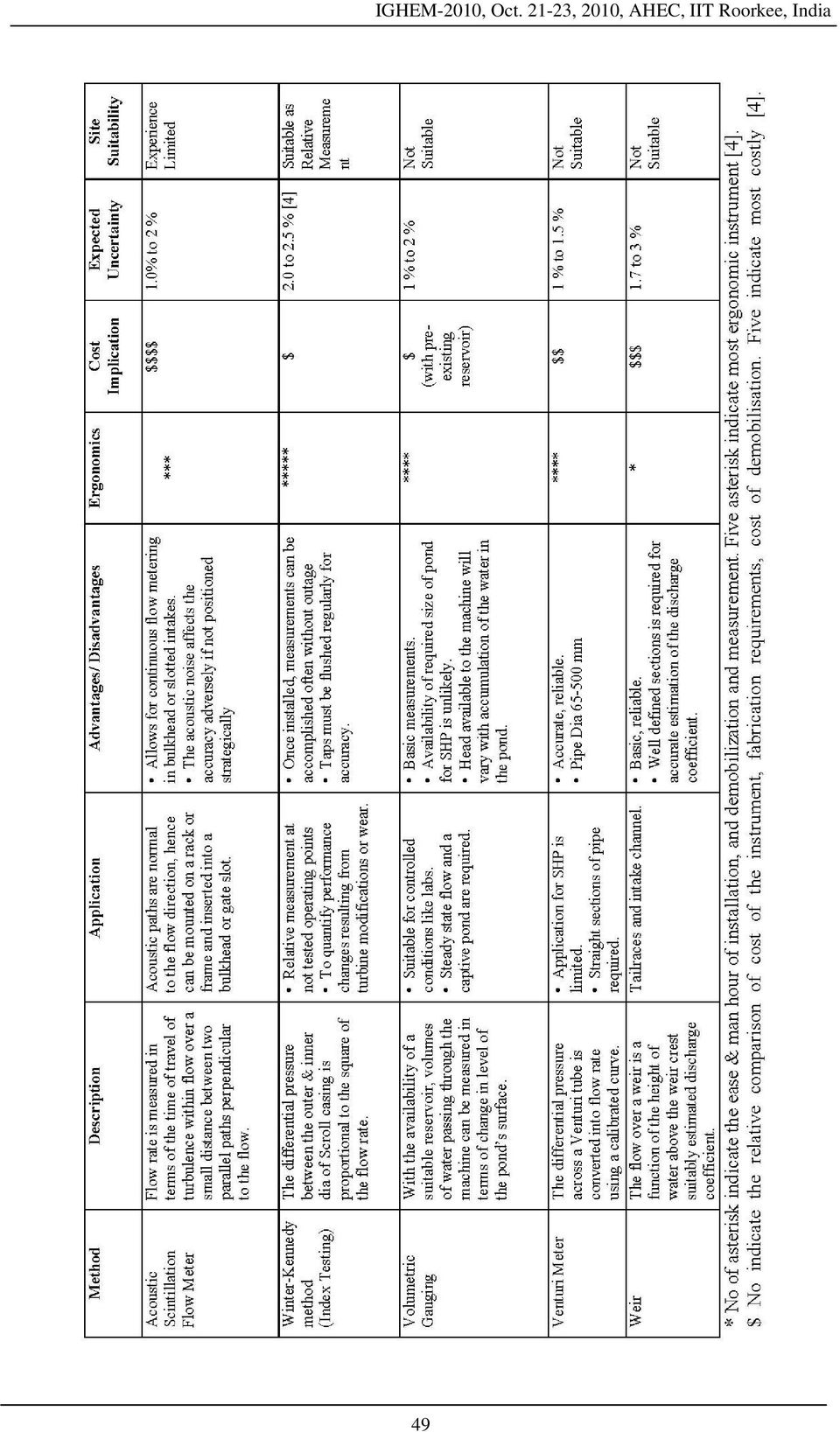
4 Factors governing the choice of the discharge measurement methods [3]: 1. Site Specific Applicability 2. Adaptability to variable operating conditions 3. Accuracy requirements 4. Cost justifiable for the scale of the project. 5. Legal constraints 6. Range of flow rates 7. Head loss 8. Operating requirements 9. Response to sediment and debris 10. Longevity of device for given environment 11. Maintenance requirements 12. Construction and installation requirements 13. Device standardization and calibration 14. Field verification, troubleshooting, and repair 15. Availability of expertise and user acceptance of new methods 16. Vandalism potential 17. Impact on environment In addition to these, dominant factors ergonomics of the Instruments, Lead time of the Instrument supplier, Time required for Installation at site, time and laborer required for performing the measurement are also plays a major role in making the choice especially for the international projects, as the cost involved is immensely sensitive to all of these. The applicability of each methods and their relative advantage and disadvantage are juxtaposed in table II [4]. After carefully weighing all the options cross plane Ultrasonic Transit time Flow (UTTF) Meter is found to be suitable for measurement of discharge at the penstock. United States Department of the Interior Bureau of Reclamation (USBR) has reported the acoustic method to be a major contributor to shorter and less expensive performance testing based on their wide experience of testing pumps and turbines in last two decades [5]. Other feasible option was current meter at the intake gate. But Current Meter method is more time consuming, costly and labor intensive [6]. Current meter method of discharge measurement also tends to be erroneous when subjected to swirl and secondary flow which is a common phenomenon in low head plants [7]. Analysis of the velocities in each acoustic path exhibits the pattern of swirl and secondary flows, which goes unnoticed and neglected in case of current meter and this affects the current-meter readings adversely. A Vertical Acoustic Doppler Profiler is chosen as the second method of discharge measurement at the tail race. Purpose of this is to cross verify the readings of the readings of UTTF installed at the penstock. The model used is River Surveyor S5 manufactured by Sontek. Both of these discharge measuring instruments were sourced locally from Taiwan Power Research Institute at Taiwan to reduce the time component and capital investment required for procurement. The comparison of the readings of both of these instruments is presented in table I. Table I. Comparison of Flow Readings UTTF Model: Yokogawa VADP Model: River Surveyor S5 Make: Sonteck Discharge (Cumecs) Discharge (Cumecs) LOAD 100 % 75 % 50 % 30 %

5 48

6 49
7 Figure 1: Instrument Allocation Scheme, ZHO Suwei (1 X 3607 kw) Performance Testing B. NET HEAD CALCULATION Net head available to the turbine can be calculated either by deducting the calculated head loss from the gross had measured or by deriving from the measured static pressure at the inlet and the out let of the turbine. The first method has an element of estimation in it. The accuracy of such measurement depends substantially upon the loss coefficient selected. However, the loss coefficients adopted from the standards and codes [8],[9] does not cater for the actual condition of the surface of the hydraulic passage hence has a possibility of being influenced by inaccurate estimation. Hence the later method is adopted for calculation of net head. 50

8 Net Head, H n = P 1 -P 2 + V V 2 ρg 2 g + (Z 1 -Z 2 ) = ΔP + V V 2 ρg 2 g + (Z 1 -Z 2 ) Where, P 1 = Pressure at up stream (U/S) of the turbine P 2 = Pressure at Down stream (D/S) of the turbine V 1 = Velocity at Location of Pressure Gauge Installation at U/S V 2 = Velocity at Location of Pressure Gauge Installation at D/S Z 1 = Level of U/S pressure Gauge Z 2 = Level of D/S pressure Gauge Up stream pressure (P 1 ) have been measured using manifolded pressure taps on the penstock. A high accuracy battery operated portable pressure transducer was installed to the manifold for taking the reading. For the down stream pressure gauges were installed at two locations. One digital pressure gauge at the draft tube cone, i.e. just below the runner and the other one pair of hydro static pressure gauge at the end of steel liner of draft exit. How ever it was observed during testing that the readings from either of them were not stable, as the one at the draft tube cone were subject to turbulence of the runner. The reading of the hydro static type pressure transducer is highly influenced by its relative orientation with the velocity of water. Hence it was mutually agreed to consider the free surface level at the draft tube gate as the down stream pressure of the turbine (P 2 ). In that case the formula for net head calculation becomes: Net Head, H n = P 1 * L tw + H v + a ρ a = Position head (m) = b + (c-d) b = Level difference between pressure transducer and penstock center line (m) c = Elevation of penstock center line (m) d = Elevation of center line of draft tube section (m) ρ = Specific gravity of water (kg/m 3 ) C. MEASUREMENT OF POWER Where, P 1 = Upstream pressure (kg/cm 2 ) H v = Velocity Head (m) = V 1 2 -V g V 1 = Velocity at upstream pressure measurement section (m/s). V 2 = Velocity at end of steel liner of draft tube (m/s). L tw = Water level above draft tube exit center line (m) IEC 41 requires electric power output measurement by a Watt meter connected through a current transformer (CT) and potential transformer (PT) of class 0.2 or better. The CT and PT installed at site are of accuracy class 0.2 hence as another step towards making the test economic those were calibrated and used for performance testing. A watt meter of accuracy class 0.1 was locally sourced from Taiwan Power Research Institute (TPRI). IV. INTERPRETATION OF RESULTS Table III. Test Results Load Q m 3 /s Vel Head (m) Net Head (m) Hydraulic Power (kw) Mechanical Power (kw) Efficiency (%) 100 % % % %

9 The result of all the measurements and calculations are presented in table III. The comparison of the tested efficiency with that of predicted efficiency form model test data is plotted in Figure II. It can be observed that there is a marginal deviation of the tested results from the predicted performance and in most of the operating points the tested results were better. At 50 % power output the actual efficiency is observed to be less than the predicted/ committed efficiency but the deviation is within the upper limit of combined uncertainty of the measurement Efficiency (%) Efficiency-Commited Efficiency-Tested Load (%) V. CONCLUSION. Figure II: Efficiency Tested vs. Efficiency Committed In case of performance testing of small scale power plants, where the economy and labor intensiveness becomes critical, careful selection of instruments becomes is very important. Various options are required to be weighted considering the lead time of the instrument supplier, man-hour required for installation, additional fabrication requirement of frame etc, ergonomics of the instrument, time required to demobilize and total down time required in addition to the estimated uncertainty of the equipments. Instrument based on new technological innovations like Doppler Profiler and UTTF may be resorted to, to obtain a balance between the accuracy and economy and ergonomics. A little modification in the methods to suit the site requirement like calculation of net head can bring in increase in ease and better accuracy in measurement. Fig. III. Installation of UTTF Fig. IV: Surface Preparation for Sensors 52
 90.00 89.00 90.02 88.00 87.00 86.65 86.50 Efficiency-Commited Efficiency-Tested 86.00 20.00 30.00 40.00 50.00 60.00 70.00 80.00 90.00 100.")
10 Fig. V: Q Measurement using Riversurveyor Fig. VI: Manifold for Upstream Pressure Fig. VII: Sectional View-Power House REFERENCE [1] PTC : The American Society of Mechanical Engineers (ASME) Performance Test Code 18. [2] IEC : Field Acceptance Test to Determine the Hydraulic Performance of Hydraulic Turbines, Storage Pumps and Pump- Turbines International Electro-technical Commission (IEC), Publication No. 41. [3] Water Measurement Manual, United States Department of the Interior Bureau of Reclamation (USBR). [4] Flow Measurement at Hydro Facilities: Achieving Efficiency, Compliance, and Optimal Operation (TR V5) A Hydropower Technology Roundup Report, Volume 5, January 2002, EPRI. [5] David et al, Turbine Performance Testing: Bureau of Reclamation s Experience, Hydroworld.com. [6] Karan et al, experience with Kaplan turbine efficiency measurement current meters and/or index test flow measurement, IGHEM international conference [7] Burch et al, Ultrasonic flow measurement for unit testing and Performance monitoring at low-head hydroelectric plants. 53
![[2] IEC 41-1991: Field Acceptance Test to Determine the Hydraulic Performance of Hydraulic Turbines, Storage Pumps and Pump- Turbines International Electro-technical Commission (IEC), Publication No.](/docs-images/47/20789908/images/page_10.jpg "41. [3] Water Measurement Manual, United States Department of the Interior Bureau of Reclamation (USBR).")
11 [8] JEC , Field efficiency test Method for Hydraulic Turbine, Japanese Electro-Technical Commission. [9] IS , Criteria for Hydraulic Design of Penstock, Bureau of Indian Standards. BIOGRAPHY Mr. Santosh Ghosh graduated in Electrical Engineering from The Institution of Engineers (India) and did his masters from Alternate Hydro Energy Center at Indian Institute of Technology (Roorkee) in He has worked in Indian Navy from 2000 to 2007 and specialized in Control and Navigation System of new generation war ships from Naval Academy, Russia. Presently he is working with Kirloskar Brothers Ltd. (India) in corporate R&D division in Turbine design group and also involved in new energy efficient product development for application in the field of renewable energy. Dr. Jagadish Kshirsagar graduated in Mechanical Engineering from Nagpur University in He obtained his ME and PhD from Indian Institute of Science, Bangalore in 1978 and 1989 respectively. His research interest includes 3D flows in turbo machinery, Numerical Analysis of fluid handling equipments. He has 28 years of industrial, academic and research experience in the field of turbo machinery. Presently he is working with Kirloskar Brothers Ltd, India in the capacity of vice president of R&D division. He is member of various professional societies like ASME, FMFP, Indian Hydraulic Society, fellow of Institute of Engineers and recognized as chattered Engineer. He is recipient of two US patents for innovative design of fluid handling system. Mr. Sudhir Mali graduated in Mechanical Engineering in 1995 and subsequently did his Masters in Design from College of Engineering, Pune (COEP). Since 1995 he is associated with Corporate R&D of Kirloskar Brothers Limited (KBL), India. Presently, he is heading the design and engineering of hydro turbines division. He has been instrumental in KBL for the technology transfer from the collaborators and bringing in innovation in turbine design. He has worked on the mechanical design and engineering for about 30 various small hydro projects done by Kirloskar Brothers Limited including Kaplan, Francis and Pelton turbines. 54

Analytical Approach for Cost Estimation of Low Head Small Hydro Power Schemes
 Analytical Approach for Cost Estimation of Low Head Small Hydro Power Schemes S.K. Singal and R.P. Saini Alternate Hydro Energy Centre, Indian Institute of Technology, Roorkee, India Email : sunilfah@iitr.ernet.in
KEYWORDS Micro hydro turbine, Turbine testing, Cross flow turbine
 DEVELOPMENT OF COST EFFECTIVE TURBINE FOR HILLY AREAS [Blank line 11 pt] A. Tamil Chandran, Senior Research Engineer Fluid Control Research Institute, Kanjikode west, Plalakkad, Kerala, India tamilchandran@fcriindia.com
HYDROMATRIX Jebel Aulia - Sudan
 HYDROMATRIX Jebel Aulia - Sudan www.andritz.com HYDROMATRIX - Concept Jebel Aulia - Sudan HYDROMATRIX is a new concept of hydraulic energy generation, which has been developed by an American engineer in
Mini & Micro Hydro Power Generation. EBARA Hatakeyama Memorial Fund Tokyo, Japan
 Mini & Micro Hydro Power Generation EBARA Hatakeyama Memorial Fund Tokyo, Japan Definitions Large Scale hydro power generation : Capacity 100(MW) Most of them involve major construction of dams. Small
Flow Measurement Calibration and Measurement
 Calibration and Measurement Flow Measurement Flow measurement for agricultural irrigation delivery can be accomplished with four general approaches. These categories are generalized below. I. Standard
Performance Improvement of Pump-turbine for Large Capacity Pumped Storage Power Plant in USA
 Performance Improvement of Pump-turbine for Large Capacity Pumped Storage Power Plant in USA 198 Performance Improvement of Pump-turbine for Large Capacity Pumped Storage Power Plant in USA 300-MW Pump-turbine
Flow Measurement Options for Pipeline and Open Channel Flow
 Flow Measurement Options for Pipeline and Open Channel Flow October 2013 Presented by Molly Skorpik - 2013 Montana Association of Dam and Canal Systems Conference Irrigation Training and Research Center
Performance of Gangrel Hydroelectric Power Plant A Case Study
 Performance of Gangrel Hydroelectric Power Plant A Case Study Bhoumika Sahu 1, Sanjiv Kumar 2, Dhananjay Kumar Sahu 3,Brijesh patel 4,Kalpit P. Kaurase 5 1 M.Tech scholar (TurboMachinary) & Mats University,
MICRO-HYDROPOWER NEED FOR ENERGY FOR RURAL DEVELOPMENT. By: Payman Hassan Rashed
 MICRO-HYDROPOWER NEED FOR ENERGY FOR RURAL DEVELOPMENT Significant water resources are found in many developing countries. In areas where adequate water resources are present, harnessing the power of falling
HYDROPOWER SYSTEMS BY APPOINTMENT TO H.M. THE QUEEN WATER TURBINE ENGINEERS, GILBERT GILKES & GORDON LTD, KENDAL
 HYDROPOWER SYSTEMS BY APPOINTMENT TO H.M. THE QUEEN WATER TURBINE ENGINEERS, GILBERT GILKES & GORDON LTD, KENDAL 1 WWW.GILKES.COM CONTENTS THE COMPANY 3 GILKES HYDROPOWER 5 GILKES PACKAGE 7 TURBINE SELECTION
RECYCLED MICRO HYDROPOWER GENERATION USING HYDRAULIC RAM PUMP (HYDRAM)
") IMPACT: International Journal of Research in Engineering & Technology (IMPACT: IJRET) Vol., Issue 3, Aug 23, - Impact Journals RECYCLED MICRO HYDROPOWER GENERATION USING HYDRAULIC RAM PUMP (HYDRAM) C.
IMPACT: International Journal of Research in Engineering & Technology (IMPACT: IJRET) Vol., Issue 3, Aug 23, - Impact Journals RECYCLED MICRO HYDROPOWER GENERATION USING HYDRAULIC RAM PUMP (HYDRAM) C.
Institut für Energietechnik Department of Energy Systems. Hydroelectric power. Elias Bartos 2/7 2010
 Institut für Energietechnik Department of Energy Systems Hydroelectric power Elias Bartos 2/7 2010 1 Contents Different types of power plants Potential Economics Conclusion 2 Impoundment A dam is built
TURBINE SELECTION RANGE
 GILKES GILKESTURGO TURGOIMPULSE IMPULSEHYDRO HYDROTURBINE TURBINE TURBINE SELECTION On 17th August 1856 we received our first order for a water turbine. It produced mechanical power to drive agricultural
DESIGN OF SMALL HYDRO ELECTRIC PROJECT USING TAILRACE EXTENSION SCHEME
 DESIGN OF SMALL HYDRO ELECTRIC PROJECT USING TAILRACE EXTENSION SCHEME Delson Jose 1, Lini Varghese 2, Renjini G. 3 1,2B.Tech Scholars Engineering College, Cheruthuruthy, Thrissur, 3Assistant Professor,
Micro-Hydro. Module 4.1. 4.1.1 Introduction. Tokyo Electric Power Co. (TEPCO)
") Module 4.1 Micro-Hydro 4.1.1 Introduction Tokyo Electric Power Co. (TEPCO) Workshop on Renewable Energies November 14-25, 2005 Nadi, Republic of the Fiji Islands Subjects to be Covered in Workshop Potential
Module 4.1 Micro-Hydro 4.1.1 Introduction Tokyo Electric Power Co. (TEPCO) Workshop on Renewable Energies November 14-25, 2005 Nadi, Republic of the Fiji Islands Subjects to be Covered in Workshop Potential
HYDRAULICS. H91.8D/C - Computerized Open Surface Tilting Flow Channel - 10, 12.5, 15 and 20 m long
 HYDRAULICS H91.8D/C - Computerized Open Surface Tilting Flow Channel - 10, 12.5, 15 and 20 m long 1. General The series of channels H91.8D has been designed by Didacta Italia to study the hydrodynamic
APPENDIX F. Baker County. Mason Dam Hydroelectric Project FERC No. P-12686. Turbidity Monitoring Plan
 APPENDIX F Baker County Mason Dam Hydroelectric Project FERC No. P-12686 Turbidity Monitoring Plan April 2011 857 Table of Contents 1.0 Introduction 1 2.0 Purpose and Scope 2 3.0 Turbidity Monitoring and
S.1 Introduction to the Case Study on Micro-Hydro Power Plants
 S.1 Introduction to the Case Study on Micro-Hydro Power Plants Micro-Hydro power is an alternative technology for power generation. This section provides a case study on the design and development of a
Head Loss in Pipe Flow ME 123: Mechanical Engineering Laboratory II: Fluids
 Head Loss in Pipe Flow ME 123: Mechanical Engineering Laboratory II: Fluids Dr. J. M. Meyers Dr. D. G. Fletcher Dr. Y. Dubief 1. Introduction Last lab you investigated flow loss in a pipe due to the roughness
Chapter 3.5: Fans and Blowers
 Part I: Objective type questions and answers Chapter 3.5: Fans and Blowers 1. The parameter used by ASME to define fans, blowers and compressors is a) Fan ration b) Specific ratio c) Blade ratio d) Twist
Index-Velocity Rating Development for Rapidly Changing Flows in an Irrigation Canal Using Broadband StreamPro ADCP and ChannelMaster H-ADCP
 Index-Velocity Rating Development for Rapidly Changing Flows in an Irrigation Canal Using Broadband StreamPro ADCP and ChannelMaster H-ADCP HENING HUANG, RD Instruments, 9855 Businesspark Avenue, San Diego,
Open Channel & Partially Filled Pipe Ultrasonic Flow Meters
 Open Channel & Partially Filled Pipe Ultrasonic Flow Meters DYNAMETERS series DMDF-OP has three types as below: DMDF-OP-A for partially filled pipe application; DMDF-OP-B for partially filled pipe, channel
HYDRO POWER GENERATION
 Course on IntegratingRenewableEnergySourcesintoEmerging ElectricPowerSystems (16-20 May, 2011) IIT Mandi SMALL HYDRO POWER GENERATION By : Dr. R.P. Saini Associate Professor AlternateHydroEnergyCentre,
An Introduction to. Micro- Hydropower. Systems. Natural Resources Canada. Ressources naturelles Canada
 An Introduction to Micro- Hydropower Systems Natural Resources Canada Ressources naturelles Canada Introduction Hydropower technology has been around for more than a century. Hydropower comes from converting
Practice Problems on Pumps. Answer(s): Q 2 = 1850 gpm H 2 = 41.7 ft W = 24.1 hp. C. Wassgren, Purdue University Page 1 of 16 Last Updated: 2010 Oct 29
: Q 2 = 1850 gpm H 2 = 41.7 ft W = 24.1 hp. C. Wassgren, Purdue University Page 1 of 16 Last Updated: 2010 Oct 29") _02 A centrifugal with a 12 in. diameter impeller requires a power input of 60 hp when the flowrate is 3200 gpm against a 60 ft head. The impeller is changed to one with a 10 in. diameter. Determine the
_02 A centrifugal with a 12 in. diameter impeller requires a power input of 60 hp when the flowrate is 3200 gpm against a 60 ft head. The impeller is changed to one with a 10 in. diameter. Determine the
Amir Bashirzadeh Tabrizi, Nassir Gifani. TOOSSAB Consulting Engineers Company e-mail: bashirzadeh@hotmail.com, nssrgifani@gmail.com.
 International Renewable Energy Congress November 5-7, 2010 Sousse, Tunisia Economical and Environmental Effects of Pressure Reducer Valve Substituting by Small Hydro Power-Plants in Gravity Water Transmission
Pumps: Convert mechanical energy (often developed from electrical source) into hydraulic energy (position, pressure and kinetic energy).
 into hydraulic energy (position, pressure and kinetic energy).") HYDRAULIC MACHINES Used to convert between hydraulic and mechanical energies. Pumps: Convert mechanical energy (often developed from electrical source) into hydraulic energy (position, pressure and kinetic
HYDRAULIC MACHINES Used to convert between hydraulic and mechanical energies. Pumps: Convert mechanical energy (often developed from electrical source) into hydraulic energy (position, pressure and kinetic
Index-Velocity Rating Development (Calibration) for H-ADCP Real-Time Discharge Monitoring in Open Channels
 for H-ADCP Real-Time Discharge Monitoring in Open Channels") Index-Velocity Rating Development (Calibration) for H-ADCP Real-Time Discharge Monitoring in Open Channels Hening Huang Teledyne RD Instruments, Inc., 14020 Stowe Drive, Poway, CA. 92064, USA (Tel: 858-842-2600,
Index-Velocity Rating Development (Calibration) for H-ADCP Real-Time Discharge Monitoring in Open Channels Hening Huang Teledyne RD Instruments, Inc., 14020 Stowe Drive, Poway, CA. 92064, USA (Tel: 858-842-2600,
A MTR FUEL ELEMENT FLOW DISTRIBUTION MEASUREMENT PRELIMINARY RESULTS
 A MTR FUEL ELEMENT FLOW DISTRIBUTION MEASUREMENT PRELIMINARY RESULTS W. M. Torres, P. E. Umbehaun, D. A. Andrade and J. A. B. Souza Centro de Engenharia Nuclear Instituto de Pesquisas Energéticas e Nucleares
Experiment 3 Pipe Friction
 EML 316L Experiment 3 Pipe Friction Laboratory Manual Mechanical and Materials Engineering Department College of Engineering FLORIDA INTERNATIONAL UNIVERSITY Nomenclature Symbol Description Unit A cross-sectional
Frequently Asked Questions (FAQs) on Hydropower
 on Hydropower") Frequently Asked Questions (FAQs) on Hydropower What are the advantages of Hydropower? A renewable source of energy - saves scarce fuel reserves. Non-polluting and hence environment friendly. Long life
Frequently Asked Questions (FAQs) on Hydropower What are the advantages of Hydropower? A renewable source of energy - saves scarce fuel reserves. Non-polluting and hence environment friendly. Long life
Flow Like An Egyptian: The Basics of Open channel flow
 Flow Like An Egyptian: The Basics of Open channel flow Walt Boyes,as ISA Life Fellow, Fellow of InstMC, Chartered Measurement and Control Technologist, Editor of Control and ControlGlobal.com and principal
Waste, Just Another Resource: A Case for Waste Water
 Energy Engineering ISSN: 0199-8595 (Print) 1546-0118 (Online) Journal homepage: http://www.tandfonline.com/loi/uene20 Waste, Just Another Resource: A Case for Waste Water David Goodman, Arash Edalatnoor
HydroHelp 1 AN EXCEL PROGRAM DEVELOPED FOR TURBINE-GENERATOR SELECTION FOR HYDROELECTRIC SITES
 HydroHelp 1 AN EXCEL PROGRAM DEVELOPED FOR TURBINE-GENERATOR SELECTION FOR HYDROELECTRIC SITES Selecting the correct turbine for a hydro site is difficult, particularly for small low-head sites. Manufacturers
Experiment (13): Flow channel
: Flow channel") Introduction: An open channel is a duct in which the liquid flows with a free surface exposed to atmospheric pressure. Along the length of the duct, the pressure at the surface is therefore constant and
Introduction: An open channel is a duct in which the liquid flows with a free surface exposed to atmospheric pressure. Along the length of the duct, the pressure at the surface is therefore constant and
Tracking the Flow: Meeting the Challenge of Open- Channel Flow Measurement in Municipal Applications
 Tracking the Flow: Meeting the Challenge of Open- Channel Flow Measurement in Municipal Applications By Jeff Smith Source: Primary Flow Signal, Inc. Open channels can be tough to measure but careful attention
MICRO HYDRO FOR THE FARM AND HOME
 MICRO HYDRO FOR THE FARM AND HOME How much can I expect to save? This depends entirely on the available flow, available head (fall) and the duration that the flow is available. Some farms struggle to maintain
What are the Benefits?
 Micro hydro power system introduction Not everyone is lucky enough to have a source of running water near their homes. But for those with river-side homes or live-on boats, small water generators (micro-hydro
How To Measure The Flow Rate Of The Sacramento River With An Adfm
 Measuring Sacramento River Diversions with ADFM Technology in the Glenn-Colusa Irrigation District Michael A. Metcalf, Ph.D., MGD Technologies Inc., 9815 Carroll Canyon Rd., Suite 2, San Diego, CA 92131,
INDIAN STANDARDS FOR NATURAL GAS PIPELINE SYSTEM
 INDIAN STANDARDS FOR NATURAL GAS PIPELINE SYSTEM 1. IS 15663(Part 1):2006 This code covers requirements and recommendations for the design, materials, construction and testing of pipelines made of steel
The original OSSBERGER Crossflow Turbine
 The original OSSBERGER Crossflow Turbine History The history of the original OSSBERGER Crossflow Turbine started with an intellectual exchange between two highly innovative geniuses: the Australian inventor
Hydroelectric Power (3 Semester Hours)
") ECET 3811 Hydroelectric Power (3 Semester Hours) I. Course Overview: Hydroelectric power is a form of hydropower which exploits the movement of water to generate electricity. Hydroelectricity is a well-established
ECET 3811 Hydroelectric Power (3 Semester Hours) I. Course Overview: Hydroelectric power is a form of hydropower which exploits the movement of water to generate electricity. Hydroelectricity is a well-established
Design of Micro-Hydro-Electric Power Station
 International Journal of Engineering and Advanced Technology (IJEAT) ISSN: 2249 8958, Volume-3, Issue-3, February 214 Design of Micro-Hydro-Electric Power Station Bilal Abdullah Nasir Abstract: Micro-hydro-electric
Wind Turbine Power Calculations
 Wind Turbine Power Calculations RWE npower renewables Mechanical and Electrical Engineering Power Industry INTRODUCTION RWE npower is a leading integrated UK energy company and is part of the RWE Group,
Power Recovery Turbines
 Power Recovery Turbines Fixed and Variable Geometry Vertical Horizontal Bulletin PS-90-1 (E) Pump Supplier To The World Flowserve is the driving force in the global industrial pump marketplace. No other
Open Channel Flow Measurement Weirs and Flumes
 Open Channel Flow Measurement Weirs and Flumes by Harlan H. Bengtson, PhD, P.E. 1. Introduction Your Course Title Here Measuring the flow rate of water in an open channel typically involves some type of
HEAVY OIL FLOW MEASUREMENT CHALLENGES
 HEAVY OIL FLOW MEASUREMENT CHALLENGES 1 INTRODUCTION The vast majority of the world s remaining oil reserves are categorised as heavy / unconventional oils (high viscosity). Due to diminishing conventional
Systems and services for small hydro power plants
 Systems and services for small hydro power plants Two become one providing more services for you The demand to generate electricity from renewable sources is a global focus. Hydro power has tremendous
Pico Power: A Boon for Rural Electrification
 Advance in Electronic and Electric Engineering. ISSN 2231-1297, Volume 3, Number 7 (2013), pp. 865-872 Research India Publications http://www.ripublication.com/aeee.htm Pico Power: A Boon for Rural Electrification
AN ECONOMICAL AND TECHNICAL CASE STUDY FOR A SMALL HYDROPOWER SYSTEM
 AN ECONOMICAL AND TECHNICAL CASE STUDY FOR A SMALL HYDROPOWER SYSTEM Dumitru Dan POP 1, Vasile Simion CRĂCIUN, Liviu Neamţ, Radu Tîrnovan, Teodor VAIDA Technical University of Cluj Napoca, dan.pop@eps.utcluj.ro
Exercise (4): Open Channel Flow - Gradually Varied Flow
: Open Channel Flow - Gradually Varied Flow") Exercise 4: Open Channel Flow - Gradually Varied Flow 1 A wide channel consists of three long reaches and has two gates located midway of the first and last reaches. The bed slopes for the three reaches
Exercise 4: Open Channel Flow - Gradually Varied Flow 1 A wide channel consists of three long reaches and has two gates located midway of the first and last reaches. The bed slopes for the three reaches
Module 3. Irrigation Engineering Principles. Version 2 CE IIT, Kharagpur
 Module 3 Irrigation Engineering Principles Lesson 9 Regulating Structures for Canal Flows Instructional objectives On completion of this lesson, the student shall be able to learn: 1. The necessity of
FLUID MECHANICS. TUTORIAL No.7 FLUID FORCES. When you have completed this tutorial you should be able to. Solve forces due to pressure difference.
 FLUID MECHANICS TUTORIAL No.7 FLUID FORCES When you have completed this tutorial you should be able to Solve forces due to pressure difference. Solve problems due to momentum changes. Solve problems involving
CHAPTER 6: ELECTROMECHANICAL EQUIPMENT CONTENTS LIST OF FIGURES. Guide on How to Develop a Small Hydropower Plant ESHA 2004
 CHAPTER 6: ELECTROMECHANICAL EQUIPMENT CONTENTS 6 Electromechanical equipment... 154 6.1 Powerhouse...154 6.2 Hydraulic turbines...156 6.2.1 Types and configuration...156 6.2.2 Specific speed and similitude...168
CENTRIFUGAL PUMP OVERVIEW Presented by Matt Prosoli Of Pumps Plus Inc.
 CENTRIFUGAL PUMP OVERVIEW Presented by Matt Prosoli Of Pumps Plus Inc. 1 Centrifugal Pump- Definition Centrifugal Pump can be defined as a mechanical device used to transfer liquid of various types. As
CE 6303 MECHANICS OF FLUIDS L T P C QUESTION BANK PART - A
 CE 6303 MECHANICS OF FLUIDS L T P C QUESTION BANK 3 0 0 3 UNIT I FLUID PROPERTIES AND FLUID STATICS PART - A 1. Define fluid and fluid mechanics. 2. Define real and ideal fluids. 3. Define mass density
A LAMINAR FLOW ELEMENT WITH A LINEAR PRESSURE DROP VERSUS VOLUMETRIC FLOW. 1998 ASME Fluids Engineering Division Summer Meeting
 TELEDYNE HASTINGS TECHNICAL PAPERS INSTRUMENTS A LAMINAR FLOW ELEMENT WITH A LINEAR PRESSURE DROP VERSUS VOLUMETRIC FLOW Proceedings of FEDSM 98: June -5, 998, Washington, DC FEDSM98 49 ABSTRACT The pressure
FLOW CONDITIONER DESIGN FOR IMPROVING OPEN CHANNEL FLOW MEASUREMENT ACCURACY FROM A SONTEK ARGONAUT-SW
 FLOW CONDITIONER DESIGN FOR IMPROVING OPEN CHANNEL FLOW MEASUREMENT ACCURACY FROM A SONTEK ARGONAUT-SW Daniel J. Howes, P.E. 1 Charles M. Burt, Ph.D., P.E. 2 Brett F. Sanders, Ph.D. 3 ABSTRACT Acoustic
Hydro Power. Chapter 4. Mohammed Taih Gatte and Rasim Azeez Kadhim. 1. Introduction
 Chapter 4 Hydro Power Mohammed Taih Gatte and Rasim Azeez Kadhim Additional information is available at the end of the chapter http://dx.doi.org/10.5772/52269 1. Introduction Humans have used the power
Equipment for Engineering Education
 Equipment for Engineering Education Instruction Manual Venturi Flume G.U.N.T. Gerätebau GmbH Fahrenberg 4 D-885 Barsbüttel Germany Phone: ++49 (40) 670854.0 Fax: ++49 (40) 670854.4 E-mail: sales@gunt.de
Small-Scale Hydroelectric Power Generation Potential: A case study of Washpen Falls Brendan Grayson-Wallace
 5 10 15 20 Small-Scale Hydroelectric Power Generation Potential: A case study of Washpen Falls Brendan Grayson-Wallace Abstract: Small-scale hydroelectric power generation provides an attractive alternative
ENVIRONMENTAL MITIGATION AT HYDROELECTRIC PROJECTS Volume 1. Current Practices for Instream Flow Needs, Dissolved Oxygen, and Fish Passage
 DOEIID-10360 Distribution Category: UC-22S ENVIRONMENTAL MITIGATION AT HYDROELECTRIC PROJECTS Volume 1. Current Practices for Instream Flow Needs, Dissolved Oxygen, and Fish Passage M. J. Sale G. F. Cada
National Electric Power Regulatory Authority
 National Electric Power Regulatory Authority MECHANISM FOR DETERMINATION OF TARIFF FOR HYDROPOWER PROJECTS Preamble Conservative estimates show total hydroelectric potential in the country to be 45000
Unit 24: Applications of Pneumatics and Hydraulics
 Unit 24: Applications of Pneumatics and Hydraulics Unit code: J/601/1496 QCF level: 4 Credit value: 15 OUTCOME 2 TUTORIAL 2 HYDRAULIC AND PNEUMATIC CYLINDERS The material needed for outcome 2 is very extensive
Michael Montgomery Marketing Product Manager Rosemount Inc. Russ Evans Manager of Engineering and Design Rosemount Inc.
 ASGMT / Averaging Pitot Tube Flow Measurement Michael Montgomery Marketing Product Manager Rosemount Inc. Russ Evans Manager of Engineering and Design Rosemount Inc. Averaging Pitot Tube Meters Introduction
Grant Agreement No. 228296 SFERA. Solar Facilities for the European Research Area SEVENTH FRAMEWORK PROGRAMME. Capacities Specific Programme
 Grant Agreement No. 228296 SFERA Solar Facilities for the European Research Area SEVENTH FRAMEWORK PROGRAMME Capacities Specific Programme Research Infrastructures Integrating Activity - Combination of
Broad Crested Weirs. I. Introduction
 Lecture 9 Broad Crested Weirs I. Introduction The broad-crested weir is an open-channel flow measurement device which combines hydraulic characteristics of both weirs and flumes Sometimes the name ramp
Copa Raked Bar Screen
 Copa Raked Bar Screen Mechanically Raked Combined Sewer Overflow (CSO) Screen Key features & benefits Stainless steel with Tivar screen comb 10mm bar spacing Complete range up to 3000 l/sec per screen
Commissioning of 87,000-kW Kaplan Turbine and Generator for Otori Power Station
 Commissioning of 87,000-kW Kaplan Turbine and Generator for Otori Power Station 126 Commissioning of 87,000-kW Kaplan Turbine and Generator for Otori Power Station Asami Sato Keiichi Goto OVERVIEW: The
FLUID FLOW Introduction General Description
 FLUID FLOW Introduction Fluid flow is an important part of many processes, including transporting materials from one point to another, mixing of materials, and chemical reactions. In this experiment, you
APPLICATION OF DENSITOMETERS TO LIQUID MEASUREMENT Class # 2010
 APPLICATION OF DENSITOMETERS TO LIQUID MEASUREMENT Class # 2010 Colin B. Blakemore Sr. Product Specialist Pipeline & Gas Measurement Products AMETEK Process Instruments 455 Corporate Boulevard Newark,
Hydropower: A closer look at Archimedes Screws. Dr Peter Walker APEM Senior Aquatic Scientist
 Hydropower: A closer look at Archimedes Screws Dr Peter Walker APEM Senior Aquatic Scientist Why am I here? To talk about Archimedes screw hydropower Topics covered: A brief, general overview of hydropower
BARREL ALIGNMENT- A CRITICAL FACTOR IN REDUCING EXTRUDER WEAR
 BARREL ALIGNMENT- A CRITICAL FACTOR IN REDUCING EXTRUDER WEAR Jeff A. Myers- BARR Inc., Onsted, MI Mike Puhalla Milacron, Batavia, OH Abstract As processors increase the demand on the extruder for increased
Strain gauge measurements of rotating parts with telemetry
 1. Abstract IGHEM 01 The 9 th International conference on hydraulic efficiency measurements Trondheim, Norway June 7 th - 30 th, 01 Strain gauge measurements of rotating parts with telemetry Johannes Löfflad,
Introduction of Duplex Pump HPD71+71 and Short-Stroke Pump HPV112+112
 Shin-ichi Kamimura Komatsu has come up with a high-pressure, large-capacity, duplex swash plate pump, HPD71+71, as the main pump for PC160-7 and a short-length, tandem swash plate pump (short-stroke pump),
American International Journal of Research in Science, Technology, Engineering & Mathematics
 American International Journal of Research in Science, Technology, Engineering & Mathematics Available online at http://www.iasir.net ISSN (Print): 2328-3491, ISSN (Online): 2328-3580, ISSN (CD-ROM): 2328-3629
Introduction. Chapter 1. 1.1 The Motivation
 Chapter 1 Introduction 1.1 The Motivation Hydroelectric power plants, like real systems, have nonlinear behaviour. In order to design turbine controllers, it was normal practice in the past, when computer
Module 7: Hydraulic Design of Sewers and Storm Water Drains. Lecture 7 : Hydraulic Design of Sewers and Storm Water Drains
 1 P age Module 7: Hydraulic Design of Sewers and Storm Water Drains Lecture 7 : Hydraulic Design of Sewers and Storm Water Drains 2 P age 7.1 General Consideration Generally, sewers are laid at steeper
Mobile field balancing reduces vibrations in energy and power plants. Published in VGB PowerTech 07/2012
 Mobile field balancing reduces vibrations in energy and power plants Published in VGB PowerTech 07/2012 Dr. Edwin Becker PRÜFTECHNIK Condition Monitoring PRÜFTECHNIK Condition Monitoring GmbH 85737 Ismaning
Methodology for Merit Order Dispatch. Version 1.0
 Methodology for Merit Order Dispatch Version 1.0 25 th April 2011 TABLE OF CONTENTS 1. OBJECTIVES... 1 2. ROADMAP FOR IMPLEMENTATION... 1 3. DEFINITIONS... 3 4. OPERATIONS PLANNING... 3 4.1. General Considerations...
Accurate Air Flow Measurement in Electronics Cooling
 Accurate Air Flow Measurement in Electronics Cooling Joachim Preiss, Raouf Ismail Cambridge AccuSense, Inc. E-mail: info@degreec.com Air is the most commonly used medium to remove heat from electronics
INTEGRATED SYSTEM FOR DATA ACQUISITION AND NUMERICAL ANALYSIS OF THE SHIP RESISTANCE PERFORMANCE IN THE TOWING TANK OF GALAÞI UNIVERSITY
 INTEGRATED SYSTEM FOR DATA ACQUISITION AND NUMERICAL ANALYSIS OF THE SHIP RESISTANCE PERFORMANCE IN THE TOWING TANK OF GALAÞI UNIVERSITY DAN OBREJA, LEONARD DOMNIªORU, FLORIN PÃCURARU University Dunãrea
Open channel flow Basic principle
 Open channel flow Basic principle INTRODUCTION Flow in rivers, irrigation canals, drainage ditches and aqueducts are some examples for open channel flow. These flows occur with a free surface and the pressure
Guide on how to refurbish low head small hydro sites
 Guide on how to refurbish low head small hydro sites Contents 1 About SHAPES PROJECT 3 2 Foreword 3 3 What s peculiar? Definitions 3 4 When to refurbish 4 5 Basic technical-economic presuppositions 4 6
1. Carry water under the canal 2. Carry water over the canal 3. Carry water into the canal
 Lecture 21 Culvert Design & Analysis Much of the following is based on the USBR publication: Design of Small Canal Structures (1978) I. Cross-Drainage Structures Cross-drainage is required when a canal
Training programme on flow measurements
 WMO / OMM Autorite du Bassin du Niger Niger-HYCOS and Volta-HYCOS Projects Training programme on flow measurements 2 nd part : Flow measurement techniques Flow measurements and calculations Definitions
2.0 BASIC CONCEPTS OF OPEN CHANNEL FLOW MEASUREMENT
 2.0 BASIC CONCEPTS OF OPEN CHANNEL FLOW MEASUREMENT Open channel flow is defined as flow in any channel where the liquid flows with a free surface. Open channel flow is not under pressure; gravity is the
STEAM TURBINE 1 CONTENT. Chapter Description Page. V. Steam Process in Steam Turbine 6. VI. Exhaust Steam Conditions, Extraction and Admission 7
 STEAM TURBINE 1 CONTENT Chapter Description Page I Purpose 2 II Steam Turbine Types 2 2.1. Impulse Turbine 2 2.2. Reaction Turbine 2 III Steam Turbine Operating Range 2 3.1. Curtis 2 3.2. Rateau 2 3.3.
USAID ENERGY POLICY PROGRAM SITE VISIT REPORT STATUS OF 4 RUN OF RIVER HYDROPOWER PROJECTS. October 2013
 USAID ENERGY POLICY PROGRAM SITE VISIT REPORT STATUS OF 4 RUN OF RIVER HYDROPOWER PROJECTS October 2013 This program is made possible by the support of the American people through the United States Agency
Assessment of hydropower resources
 Assessment of hydropower resources Oliver Froend Assessment of hydropower resources Relevance of surveys, data assessment and analyses to the success of the project. Required data and field survey. Key
A Comparison of Analytical and Finite Element Solutions for Laminar Flow Conditions Near Gaussian Constrictions
 A Comparison of Analytical and Finite Element Solutions for Laminar Flow Conditions Near Gaussian Constrictions by Laura Noelle Race An Engineering Project Submitted to the Graduate Faculty of Rensselaer
Case Study 5 Use of Wind Turbine Technology
 Case Study 5 Use of Wind Turbine Technology 1. Context Hong Kong relies on an adequate and reliable electricity supply for its economic development. Our electricity needs are met by the two electricity
Smart Electromagnetic Flowmeter Open channel Flowmeter Detector
 Magne3000 PLUS Smart Electromagnetic Flowmeter Open channel Flowmeter Detector Model NNK150/951 OVERVIE The Magne3000 PLUS Electromagnetic Flowmeter is submersible type of flowmeter mainly used for flow
Selection and Use of Water Meters for Irrigation Water Measurement 1
 ABE18 Selection and Use of Water Meters for Irrigation Water Measurement 1 Melissa C. Baum, Michael D. Dukes, and Dorota Z. Haman 2 The demand for water by agriculture, industry, urban users, and recreation
525-MVA Generator-motor and Thyristor Starter Put into Service at the Tokyo Electric Power Co., Inc. s Kannagawa Hydroelectric Power Station
 525-MVA Generator-motor and Thyristor Starter Put into Service at the Tokyo Electric Power Co., Inc. s Kannagawa Hydroelectric Power Station 114 525-MVA Generator-motor and Thyristor Starter Put into Service
Steven R. McManus Environmental Product Support Teledyne Isco
 Steven R. McManus Environmental Product Support Teledyne Isco Flow Measurement Applications and Technologies. Methods of flow measurement Technologies of flow measurement Flow Rate Applications Channel
Lecture 24 Flumes & Channel Transitions. I. General Characteristics of Flumes. Flumes are often used:
 Lecture 24 Flumes & Channel Transitions I. General Characteristics of Flumes Flumes are often used: 1. Along contours of steep slopes where minimal excavation is desired 2. On flat terrain where it is
www.klmtechgroup.com TABLE OF CONTENT
 Page : 1 of 24 Project Engineering Standard www.klmtechgroup.com KLM Technology #03-12 Block Aronia, Jalan Sri Perkasa 2 Taman Tampoi Utama 81200 Johor Bahru Malaysia S TABLE OF CONTENT SCOPE 2 DEFINITIONS
Design and manufacturing of Crossflow, Pelton, Kaplan and Francis turbines
 Design and manufacturing of Crossflow, Pelton, Kaplan and Francis turbines Founded in 1990 as a manufacturer of hydro power plant equipment In 2005, the company underwent complete modernization and extended
www.klmtechgroup.com TABLE OF CONTENT
 Page : 1 of 26 Project Engineering Standard www.klmtechgroup.com KLM Technology #03-12 Block Aronia, Jalan Sri Perkasa 2 Taman Tampoi Utama 81200 Johor Bahru Malaysia TABLE OF CONTENT SCOPE 2 REFERENCES