wilkinsonstar.com TIG 200P DC Pulse TIG / MMA Welding - Dual voltage Order code JT-200PDV OPERATOR MANUAL
|
|
|
- Ethel Houston
- 7 years ago
- Views:
Transcription
1 wilkinsonstar.com TIG 200P DC Pulse TIG / MMA Welding - Dual voltage Order code JT-200PDV OPERATOR MANUAL

2 Your new product Thank you for selecting this Jasic Technology, Wilkinson Star product. This product manual has been designed to ensure that you get the most from your new product. Please ensure that you are fully conversant with the information provided paying particular attention to the safety precautions. The information will help protect yourself and others against the potential hazards that you may come across. Please ensure that you carry out daily and periodic maintenance checks to ensure years of reliable and trouble free operation. Wilkinson Star Limited are a leading supplier of equipment in the UK and our products are supported by our extensive service network. Call your distributor in the unlikely event of a problem occurring. Please record below the details from your product as these will be required for warranty purposes and to ensure you get the correct information should you require assistance or spare parts. Date purchased From where Serial Number (The serial number will normally be located on the equipment data plate on the underside of the machine or on the rear panel) Please note products are subject to continual development and may be subject to change without notice i

3 1 Safety Precautions These general safety norms cover both arc welding machines and plasma cutting machines unless otherwise noted. The equipment must only be used for the purpose it was designed for. Using it in any other way could result in damage or injury and in breach of the safety rules. Only suitably trained and competent persons should use the equipment. Operators should persons. Prevention against electric shock respect the safety of other The equipment should be installed by a qualified person and in accordance with current standards in operation.it is the users responsibility to ensure that the equipment is connected to a suitable power supply. Consult with your utility supplier if required If earth grounding of the work piece is required, ground it directly with a separate cable. Do not use the equipment with the covers removed. Do not touch live electrical parts or parts which are electrically charged. Turn off all equipment when not in use. Cables (both primary supply and welding) should be regularly checked for damage and overheating. Do not use worn, damaged, under sized, or poorly jointed cables. Ensure that you wear the correct protective clothing, gloves, head and eye protection. Insulate yourself from work and ground using dry insulating mats or covers big enough to prevent any physical contact with the work ground. Never touch the electrode if you are in contact with the work ground, or another electrode from a different machine. Do not wrap cables over your body. Ensure that you take additional safety precautions when you are welding in electrically hazardous conditions such as damp environments, wearing wet clothing, and metal structures. Try to avoid welding in cramped or restricted positions. Ensure that the equipment is well maintained. Repair or replace damaged or defective parts immediately. Carry out any regular maintenance in accordance with the manufacturers instructions. Safety against fumes and welding gases Locate the equipment in a well-ventilated position. Keep your head out of the fumes. Do not breathe the fumes. Ensure the welding zone is in a well-ventilated area. If this is not possible provision should be made for suitable fume extraction. If ventilation is poor, wear an approved respirator. Read and understand the Material Safety Data Sheets (MSDS s) and the manufacturer s instructions for metals, consumable, coatings, cleaners, and de-greasers. Do not weld in locations near any de-greasing, cleaning, or spraying operations. Be aware that heat and rays of the arc can react with vapours to form highly toxic and irritating gases. 2

4 Do not weld on coated metals, unless the coating is removed from the weld area, the area is well ventilated, and while wearing an air-supplied respirator. The coatings on many metals can give off toxic fumes if welded. Prevention against burns and radiation Arc rays from the welding process produce intense, visible and invisible (ultraviolet and infrared) rays that can burn eyes and skin. Wear an approved welding helmet fitted with a proper shade of filter lens to protect your face and eyes when welding or watching Wear approved safety glasses with side shields under your helmet. Never use broken or faulty welding helmets. Always ensure there are adequate protective screens or barriers to protect others from flash, glare and sparks from the welding area. Ensure that there are adequate warnings that welding or cutting is taking place. Wear suitable protective flame resistant clothing. The sparks and spatter from welding, hot work pieces, and hot equipment can cause fires and burns Welding on closed containers, such as tanks, drums, or pipes, can cause them to explode. Accidental contact of electrode to metal objects can cause arcs, explosion, overheating, or fire. Check and be sure the area is safe and clear of inflammable material before carrying out any welding. Protection against noise Some welding and cutting operations may produce noise. Wear safety ear protection to protect your hearing. Protection from moving parts When the machine is in operation keep away from moving parts such as motors and fans. Moving parts, such as the fan, may cut fingers and hands and snag garments. Replace the coverings and protections and close all doors when the intervention is finished, and before starting the equipment. Take care to avoid getting fingers trapped when loading and feeding wire during set up and operation. When feeding wire be careful to avoid pointing it at other people or toward your body. Always ensure machine covers and protective devices are in operation. Precautions against fire and explosion Avoid causing fires due to sparks and hot waste or molten metal Ensure that appropriate fire safety devices are available near the cutting / welding area. Remove all flammable and combustible materials from the cutting / welding zone and surrounding areas Do not cut/weld fuel and lubricant containers, even if empty. These must be carefully cleaned before they can be cut/ welded. Always allow the cut/welded material to cool before touching it or placing it in contact with combustible or flammable material. Do not work in atmospheres with high concentrations of combustible fumes, flammable gases and dust. Always check the work area half an hour after cutting to make sure that no fires have begun. Risks due to magnetic fields The magnetic fields created by high currents may affect the operation of pacemakers or electronically controlled medical equipment. Wearers of vital electronic equipment should consult their physician before beginning any arc welding, cutting, gouging or spot welding operations. Do not go near welding equipment with any sensitive electronic equipment as the magnetic fields may cause damage. Protections and coverings may be removed for maintenance and controls only by qualified personnel, after first disconnecting the power supply cable. 3

5 RF Declaration Equipment that complies with directive 2004/108/EC concerning electromagnetic compatibility (EMC) and the technical requirements of EN is designed for use in industrial buildings and not those for domestic use where electricity is provided via the low voltage public distribution system. Difficulties may arise in assuring class A electromagnetic compatibility for systems installed in domestic locations due to conducted and radiated emissions. Keep your head and face away from the cylinder valve outlet when opening the cylinder valve. Always secure the cylinder safely Never deface or alter any cylinder In the case of electromagnetic problems, it is the responsibility of the user to resolve the situation. It may be necessary to shield the equipment and fit suitable filters on the mains supply. LF Declaration Consult the data plate on the equipment for the power supply requirements. Due to the elevated absorbance of the primary current from the power supply network, high power systems affect the quality of power provided by the network. Consequently, connection restrictions or maximum impedance requirements permitted by the network at the public network connection point must be applied to these systems. In this case the installer or the user is responsible for ensuring the equipment can be connected, consulting the electricity provider if necessary. Materials and their disposal The equipment is manufactured with materials, which do not contain any toxic or poisonous materials dangerous to the operator. When the equipment is scrapped, it should be dismantled separating components according to the type of materials. Do not dispose of the equipment with normal waste. The European Directive 2002/96/EC on Waste Electrical and Electronic Equipment states the electrical equipment that has reached its end of life must be collected separately and returned to an environmentally compatible recycling facility. Handling of Compressed gas cylinders and regulators All cylinders and pressure regulators used in welding operations should be handled with care. Never allow the electrode, electrode holder or any other electrically hot parts to touch a cylinder. 4

6 2 Product Overview The unique electronic structure and air channel design in this series of machines provides efficient cooling of the power devices as well as improving the duty cycles of the machines. The design of the forced air-cooling system channel can effectively prevent the power devices and control circuits from being damaged by the dust introduced into the machine by the fan. The reliability of the machine is greatly improved as a result. The streamline design means front and rear panels are naturally integrated via large-radian transition. The front and rear panels of the machine and the handle are coated with rubber oil*, giving the machine a very tactile and comfortable grip with an excellent appearance. Product functions DC TIG, Pulsed TIG and MMA modes are available. Easy to use intuitive digital control panel for setting of parameters. LED display Rotary encoder control Hot start arc ignition function. Arc force current control 2T/4T and spot function. Upslope, Downslope, pre and post-flow gas function all adjustable Full control of pulse parameters Self-adaptive arc force technology improves the performance of the machine when using long-cable welding. Excellent HF arc ignition: High reliability arc striking. Advanced arc ignition by lift arc: TIG welding without HF arc ignition circuit. Over current, under-voltage and overheating protection functions are standard. Fault memory display Memory function Product performance characteristics Advanced IGBT inverter technology Inverting frequency of 33~43 khz greatly reduces the size and weight of the welder. Great reduction in magnetic and resistance loss enhances the welding efficiency and energy saving effect. Working frequency is beyond the audio range, which almost eliminates noise pollution. Industry leading control system Advanced control technology meets the various welding applications and provides excellent welding performance. It can be used with a wide range of welding electrodes. Easy arc starting, less spatter, stable current and good weld bead shaping. Modern high tech design Streamline design of front and rear panels. Front and rear panels made of high-intensity plastics suitable for working in severe conditions. Excellent insulating property. Water-resistant, antistatic and anticorrosion design. 5

7 3 Technical data Technical Parameter Unit Model TIG180P (JT-180PDV) TIG200P (JT-200PDV) Rated input voltage V AC110V±15%; 50/60HZ AC230V±15%; 50/60HZ AC110V±15%; 50/60HZ AC230V±15%; 50/60HZ Rated input power MMA TIG KVA Welding current range MMA TIG A 19~90 10~150 10~100 10~180 10~110 10~180 10~130 10~200 Rated duty cycle 1 % 35 No-load voltage MMA TIG V Pre-flow time s 0~15 Upslope time s 0~60 Downslope time s 0~60 Post-flow time s 0~20 Pulse duty s 20~70 Pulse frequency Hz 0.5~200 Overall efficiency % 85 Power factor cosφ 0.7 Arc ignition mode HF arc ignition Housing protection grade IP 21S Insulation grade Size without handle with handle 2 mm F 365*135* *135*277 Weight kg Tested at the environment temperature of 40 0 C 2- Product design may vary due to customer requirements. 6

8 4 Controls Front view 1. Operating panel: To set the parameters output terminal 3. - output terminal 4. Control terminal: To connect the signal wire of the TIG torch trigger. 5. Gas terminal: To connect the gas hose of the TIG torch. 6. Handle Rear view 7. Power switch: Power ON/OFF switch. 8. Warning sign 9. Power input: Power input cable. 10. Cooling fan 11. Gas inlet: For shield gas input. Control Panel 1. Display screen 2. Welding parameter selecting key 3. Operation mode selecting key 4. Welding parameter adjusting knob: The parameter adjusting encoder is used to adjust the parameters, and parameters can be adjusted by turning the knob clockwise or counterclockwise. 5. Welding mode selecting key 7

9 6. Indicator for pulsed TIG 7. Indicator for DC TIG 8. Indicator for MMA 9. Indicator for 2T 10. Indicator for 4T 11. Indicator for spot welding 12. Indicator for base current 13. Indicator for welding current 14. Indicator for upslope 15. Indicator for initial current 16. Indicator for pre-flow 17. Indicator for pulse duration ratio 18. Indicator for frequency 19. Indicator for arc ignition/spot welding time 20. Indicator for arc force current 21. Indicator for post-flow 22. Indicator for pilot arc current 23. Indicator for downslope 24. Protection indicator 25. Indicator for output voltage 8

10 Parameter autosaving The parameters having been adjusted will be autosaved in the parameter group currently used (no autosaving will be done in the case that no operation is done after parameters are adjusted and the machine was turned off in 5s time). When the machine is turned on next time, the parameters in each parameter group are the parameters used during the last operation. Protection Function When the over current indicator illuminates and the digital meter displays E-1, it indicates that over current occurs. Restart the machine, and welding can be continued. When the under-voltage indicator illuminates and the digital meter displays E-2, it indicates that the mains voltage is too low, and welding can be recovered when the mains voltage goes into normal operating range. When the overheating indicator illuminates and the digital meter displays E-3, it indicates that welding is forced to stop because the main circuit of the machine gets overheated. In this condition, It is unnecessary to turn off the machine, but just wait until the unit cools, and then welding can be continued. When the current sensor fails and the digital meter displays E-4, welding may still be carried out. However, the current value at this time is inaccurate. Foot control option This machine can identify the foot control automatically. The machine will enter into foot control mode automatically after the plug of the foot control is connected to the welding machine and the machine is powered on again. In foot control mode, the maximum current is the preset current and the minimum current is 10A. Voltage indicator When this indicator illuminates, it indicates that there is voltage output at the output terminals of the welding machine. When TIG is selected as the welding mode, there will be voltage output only when the torch trigger is pressed continuously and after arc is ignited successfully. When MMA is selected as the welding mode, there will be voltage output whether arc is ignited or not. 9

11 5 Installation Unpacking Check the packaging for any signs of damage. Carefully remove the machine and retain the packaging until the installation is complete. Insert the cable plug of the work return lead into the - socket on the front panel of the welding machine, and tighten it clockwise Location The machine should be located in a suitable position and environment. Care should be taken to avoid moisture, dust, steam, oil or corrosive gases Place on a secure level surface and ensure that there is adequate clearance around the machine to ensure natural airflow. Input connection Before connecting the machine you should ensure that the correct supply is available. Details of the machine requirements can be found on the data plate of the machine or in the technical parameters shown in the manual. The equipment should be connected by a suitably qualified competent person. Always ensure the equipment has a proper grounding. Never connect the machine to the mains supply with the panels removed. TIG Welding Insert the cable plug with the work clamp into the + socket on the front panel of the welding machine, and tighten it clockwise. Insert the cables plug of the TIG torch into the - socket on the front panel of the machine and tighten clockwise. Connect the TIG torch control switch into the socket on the machine front panel. Output connections Electrode polarity In general when using manual arc welding electrodes the electrode holder is connected the the positive terminal and the work return to the negative terminal. Always consult the electrode manufacturer s data sheet if you have any doubts. When using the machine for TIG welding the TIG torch should be connected to the negative terminal and the work return to the positive terminal MMA welding Insert the cable plug with electrode holder into the + socket on the front panel of the welding machine, and tighten it clockwise. Connect the gas hose to the regulator / flowmeter located on the shield gas cylinder and connect the other end to the machine. 10

12 Operation Before starting any welding activity ensure that you have suitable eye protection and protective clothing. Also take the necessary steps to protect any persons within the area. MMA After connecting the welding leads as detailed you will need to switch the power switch on the back panel to ON Select MMA mode by pressing the welding mode selecting key, and MMA can be carries out. There is voltage output at both output terminals. At this time, the voltage indicator illuminates, and welding can be carried out. Set the amperage on the machine suitable for the electrode being used. Please see below a guide to amperages required. Ensure you check that you have the electrode polarity correct. Electrode Diameter (mm) Recommended Welding Current (A) ~ ~ ~ ~ ~ ~ ~ ~260 Select arc ignition time setting function (This function changes into spot welding time setting function in TIG spot welding mode.) by pressing the welding parameter selecting key, and arc ignition time in MMA can be set. This sets the arc ignition time. Standard TIG mode Connect the TIG torch leads as detailed above. Ensure that a suitable inert gas supply is connected. Switch the power switch on the back panel to ON Select the TIG welding mode using the selector switch. Select the TIG operating mode (2T, 4T or Spot) using the selector switch. 2T: Press the torch trigger, gas valve opens, and HF arc ignition starts; Keep the torch 2~4mm away from the work piece to ignite the arc. When the arc is established the HF stops, and current rises to the preset value; Release the torch trigger, current decreases to the minimum value, and then arc stops; Gas keeps flowing for the post-flow time, and welding ends. 4T: Press the torch trigger, gas valve opens, and HF arc ignition starts; Keep the torch 2~4mm away from the work piece to ignite the arc. When the arc is established the HF stops, and current rises to the preset value; Release the torch trigger, and welding continues at the preset current level. Press the torch trigger again and release it, current begins to decrease to the minimum value, and then arc stops; Gas keeps flowing for the post-flow time, and welding ends. After the parameters are set appropriately For control keys see below), open the gas valve of the cylinder, and adjust the gas regulator to obtain the desired flow rate. Keep the torch 2~4mm away from the work piece, and then press the torch trigger. The gas solenoid valve operates. The gas will flow, and then HF output will start. After arc is ignited, the HF discharge will cease, the current rises up to the preset value, and welding can be carried out. After releasing the torch trigger, the current begins to decrease as determined by the downslope setting to the pilot arc value. Then, arc stops with gas kept flowing for the post-flow time, and welding ends. Spot TIG mode Select the spot welding mode by pressing the operation mode selecting key. Select the spot welding time the welding parameter selecting key, and set the spot welding time. Operation steps in spot welding: 11

13 Press the torch trigger, gas valve opens, and HF arc ignition starts; Keep the torch 2~4mm away from the work piece to ignite the arc. When the arc is ignited the HF stops, and current rises to the preset value. Welding begins, and it ends when the preset spot welding time is reached. There is no current upslope and downslope in spot welding mode. TIG guides The recommended size of tungsten to be used can be selected from the table below The welding current reference for different electrode diameter Electrode diameter /mm Welding current /A Electrode type Type Mode Colour Thoriated 2% Ceriated Lanthanated DC welding of steel, stainless steel and copper DC welding of steel, stainless steel and copper DC welding of steel, stainless steel and copper Red Grey Black The corresponding relationship between gas nozzle diameter and electrode diameter Gas nozzle diameter/mm Electrode diameter/mm or For welder training please visit our Academy website at 12

14 Control keys Standard TIG Mode Select the pre-flow time t h e w e l d i n g p a r a m e t e r selecting key, and then set the pre-flow time. Select the initial current t h e w e l d i n g p a r a m e t e r initial current. Select the upslope time t h e w e l d i n g p a r a m e t e r upslope time. Select the welding current t h e w e l d i n g p a r a m e t e r welding current. Select the downslope time t h e w e l d i n g p a r a m e t e r downslope time. Select the pilot arc current t h e w e l d i n g p a r a m e t e r pilot arc current. Select the post-flow time t h e w e l d i n g p a r a m e t e r post-flow time. Pulsed TIG mode Select the pre-flow time t h e w e l d i n g p a r a m e t e r selecting key, and then set the pre-flow time. Select the upslope time the welding parameter upslope time. Select the welding current the welding parameter welding current. Select the base current the welding parameter base current. Select the downslope time the welding parameter downslope time. Select the pilot arc current the welding parameter pilot arc current. Select the post-flow time the welding parameter post-flow time. Select the pulse duration ratio setting function by p r e s s i n g t h e w e l d i n g parameter selecting key, and set the pulse duration ratio. Select pulse frequency the welding parameter pulse frequency. Select the initial current t h e w e l d i n g p a r a m e t e r i n i t i a l c u r r e n t. 13

15 6 Maintenance and troubleshooting The following operation requires sufficient professional knowledge on electric aspects and comprehensive safety knowledge. Make sure the input cable of the machine is disconnected from the electricity supply and wait for 5 minutes before removing the machine covers. In order to guarantee that the arc welding machine works efficiently and in safety, it must be maintained regularly. Operators should understand the maintenance methods and means of arc welding machine operation. This guide should enable customers to carry on simple examination and safeguarding by oneself, try to reduce the fault rate and repair times of the arc welding machine, so as to lengthen service life of arc welding machine Period Daily examination Monthly examination Yearly examination Maintenance item Carry out a full visual inspection. Check for any damage to the machine, leads, cables and connections. Replace where necessary. Switch on the machine and check for any warning Led s and general operation Using the dry compressed air to clean the inside of arc welding machine. Especially check for build up of dust / debris on intake grills, main voltage transformer, inductance, IGBT module, the fast recover diode and PCB, etc. Take care when blowing electronic components and do not dislodge any wiring connections Check the security of output connections and plugs. Replace if signs of overheating. Carry out an annual service. Check earth continuity and insulation resistance of the machine at the relevant points. PLEASE NOTE THIS WORK SHOULD BE CARRIED OUT BY A TRAINED COMPETENT PERSON. Troubleshooting Before arc welding machines are dispatched from the factory, they have already been checked thoroughly. The machine should not be tampered with or altered. Maintenance must be carried out carefully. If any wire becomes loose or is misplaced, it maybe potential danger to user! Only professional maintenance personnel should repair the machine! Ensure the power is disconnected before working on the machine. Always wait 5 minutes after power switch off before opening the case. Malfunction symptom Causes and Solutions Turn on the machine, the power LED 1 Check if the power switch is closed. is off, the fan doesn't work, and no 2 No input power. welding output. Turn on the machine, the fan works, 1 The current potentiometer fails. Replace but the output current is unstable it. and can't be controlled by 2 Check if any loose contact exists inside potentiometer when welding. the machine. If any, reconnect. 1 Check if any loose contact exists inside the machine. 2 Open circuit or loose contact occurs at the joint of output terminal. 3 The overheating LED is on. Turn on the machine,, the fan works, The machine is under over-heating p r o t e c t i o n s t a t u s. I t c a n r e c o v e r but no welding output. automatically after the welding machine is cooled. 4 Check if the thermal switch is ok. Replace it if damaged. 5 Check if the thermal switch is loosely connected, and reconnect it if necessary. The electrode holder becomes very smaller than its actual working current. hot. Excessive spatter in MMA welding. The rated current of the electrode holder is Replace it with a higher rated current capacity. The output polarity connection is incorrect. Exchange the polarity. 14

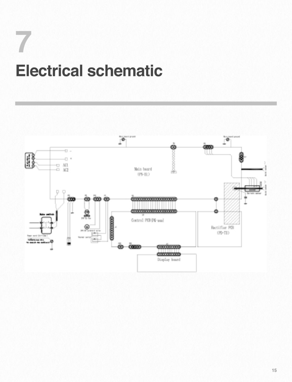
16 7 Electrical schematic 15
17 8 Parts list 16

18 No. Part no Description No. Part no Description Power switch IRF9Z24N Power line IRFZ24N Connector for input gas Driver transformer TIG200P Dual voltage fan Thermal switch Back Panel Switching mode power supply transformer Handle V Electric reply Louver TOP266KG Bottom panel KA Isolation transformer Solenoid value Quick socket Pin insulation cover Front Panel Knob TIG200P Dual voltage electrolytic capacitor TIG200P Dual voltage silicon bridge board Display panel TIG200P Dual voltage IGBT EPC connection between hose and gas connector Hose TIG200P Dual voltage control board Air socket Arc Coil TIG200P Dual voltage high frequency transformer Machine Cover Rectifier board Electric Relay Thermal resistor

19 TIG 200PDV DC TIG/MMA WELDING MACHINE Part number JT-200PDV Wilkinson Star Limited Issue 1 January 2014 Product is subject to change without notice xviii

20 JT-200 DC Pulsed TIG Series DC TIG/MMA WELDING MACHINE Order code! JT-200PDV (TIG 200PDV) Wilkinson Star Limited Issue 1 January 2014 Product is subject to change without notice xix

TIG INVERTER INSTRUCTION MANUAL
 TIG INVERTER INSTRUCTION MANUAL Contents Warning General Description Block Diagram Main Parameters Circuit Diagram Installation and Operation Caution Maintenance Spare Parts List Troubleshooting 3 4 4
SVENSKA.......................................................3 DANSK.........................................................10 NORSK................
 Caddy 150 & Caddy Tig 150 LHQ 150, LTV 150 SVENSKA.......................................................3 DANSK.........................................................10 NORSK.........................................................17
SMARTY 160 POWER page 4-5 SMARTY 180 / 220 XL page 4-6 SMARTY TX 250 page 4-7. SMARTY TX 160 Alu page 4-8 SMARTY TX 220 Alu page 4-9
 CHAPTER TIG welding Introduction pages - & - WELDING POWER SOURCES DC power sources SMARTY 60 POWER page -5 SMARTY 80 / 0 XL page -6 SMARTY TX 50 page -7 AC/DC power sources SMARTY TX 60 Alu page -8 SMARTY
UNI FLAME AUTOLIFT MIG/MMA/TIG. 165/190/220/250 Inverter Manual. 240 Volt. Standard MIG / MAG
 UNI FLAME AUTOLIFT MIG/MMA/TIG 165/190/220/250 Inverter Manual 240 Volt Standard MIG / MAG UNI FLAME AUTOLIFT 2YEARS Warranty * Machine Model Description Part Number MIG/MM/TIG Inverter KUMJR165 / 190
Portable Air Conditioner
 Portable Air Conditioner Owner's Manual Model:3 in 1 12,000 Btu/h Series 3 Please read this owner s manual carefully before operation and retain it for future reference. CONTENTS 1. SUMMARY...1 2. PORTABLE
120Volt 60-70A ARC WELDER. 80000 Rev 80000-20080214
 80000 Rev 80000-20080214 10006 Santa Fe Springs Road Santa Fe Springs, CA 90670 USA Made in China Owner s Manual and Operating Instructions 120Volt 60-70A ARC WELDER Table of Contents Introduction...
WEEKLY SAFETY MEETING All Euramax Subsidiaries WELDING SAFETY / HOT WORK SAFETY. Safety Meeting Contents. Meeting Notice.
 Safety Meeting Contents Meeting Notice Leaders Guide Employee Handout Employee Quiz Meeting Sign-In Sheet Employee Puzzle PRIOR TO THE WEEKLY MEETING: - Post the meeting notice by the timeclock - Read
INFRARED QUARTZ WALL HEATER
 INFRARED QUARTZ WALL HEATER MODEL NO: IQ2000 PART NO: 6939004 MOUNTING & OPERATION INSTRUCTIONS GC0715 INTRODUCTION Thank you for purchasing this CLARKE Infrared Wall Heater. Before attempting to use this
USER INSTRUCTIONS FOR 10 LITRE PORTABLE DEHUMIDIFIER MODEL NO. DHMD102
 USER INSTRUCTIONS FOR 10 LITRE PORTABLE DEHUMIDIFIER MODEL NO. DHMD102 THANK YOU FOR CHOOSING YOUR NEW DEHUMIDIFIER. BEFORE USING THE UNIT READ THESE INSTRUCTIONS FULLY AND RETAIN THEM FOR FUTURE REFERENCE
IMPORTANT SAFETY INSTRUCTIONS WARNING READ AND SAVE THESE OPERATING AND SAFETY INSTRUCTIONS BEFORE USING THIS HEATER.
 THERMAWAVE CERAMIC HEATER Model HZ-850 Series Model HZ-860 Series IMPORTANT SAFETY INSTRUCTIONS WARNING READ AND SAVE THESE OPERATING AND SAFETY INSTRUCTIONS BEFORE USING THIS HEATER. Warning Failure to
Installation Instructions for Alarm Module Kit A043F059
 Instruction Sheet 07-2013 Installation Instructions for Alarm Module Kit A043F059 1 Introduction The information contained within is based on information available at the time of going to print. In line
WELDING POSITIONER 00337OG091207 WARNINGS, SAFEGUARDS & OPERATING INSTRUCTIONS
 WELDING POSITIONER 00337OG09207 WARNINGS, SAFEGUARDS & OPERATING INSTRUCTIONS Warnings and Safeguards for Welding and Cutting Operations IMPORTANT - Protect yourself and others! Remember that safety depends
Installation and safety instructions for AC/DC built-in devices
 The device type and date of manufacture (week/year) can be found on the device rating plate. In the event of any queries about the device, please quote all the details given on the rating plate. For further
National- Spencer Inc.
 9-27-2010 National- Spencer Inc. 19.2V HEAVY DUTY GREASE GUN PRODUCT SPECIFICATION Charger Input Power 110 VAC Battery Output Power 19.2V Battery Capacity 1500 MAH Battery Pack Charge Time 1 Hour Maximum
Oxy-Fuel Gas Welding. Given a functional oxy-fuel gas unit, instruction and demonstration of use, each student will be able to:
 I. Competencies Oxy-Fuel Gas Welding Given a functional oxy-fuel gas unit, instruction and demonstration of use, each student will be able to: A. Identify the major parts of the oxy-fuel gas unit. B. Pass
PLASMA CUTTER - 35 AMP
 PLASMA CUTTER - 35 AMP 45949 ASSEMBLY AND OPERATING INSTRUCTIONS 3491 Mission Oaks Blvd., Camarillo, CA 93011 Visit our Web site at http://www.harborfreight.com Copyright 2003 by Harbor Freight Tools.
SMD Rework Station TABLE OF CONTENTS
 SMD Rework Station Thank you for purchasing the Hakko 50B SMD Rework Station. The Hakko 50B is designed to solder and desolder surface mounted devices with hot air. Please read this manual before operating
Kemppi Mastertig MLS 2500 and 3500. Welding Versatility for Professionals
 Kemppi Mastertig MLS 2500 and 3500 Welding Versatility for Professionals Kemppi Mastertig MLS 2500 and 3500 Welding Versatility for Professionals The Mastertig MLS 2500 and 3500 offer outstanding TIG performance
SBC90. Abrasive Blast Cabinet Assembly & Operating Instructions
 SBC90 Abrasive Blast Cabinet Assembly & Operating Instructions READ ALL INSTRUCTIONS AND WARNINGS BEFORE USING THIS PRODUCT. SAVE THESE INSTRUCTIONS FOR FUTURE REFERENCE. This manual provides important
English. Symbols used to mark instructions...3. Congratulations...5 Getting the best results...5. Warnings...6 Operating Procedure...
 2 Contents Components Attachments Guidance Installation Operation Maintenance Service Technical Troubleshooting Symbols used to mark instructions...3 Included Attachments...4 Congratulations...5 Getting
PS07572. ARC Welder Assembly & Operating Instructions
 PS07572 201107 ARC Welder Assembly & Operating Instructions READ ALL INSTRUCTIONS AND WARNINGS BEFORE USING THIS PRODUCT. This manual provides important information on proper operation & maintenance. Every
FOR THE FOLLOWING MODELS: EE-8075W EE-8075O EE-8075R EE-8075BK
 FIREPLACE HEATER FOR THE FOLLOWING MODELS: EE-8075W EE-8075O EE-8075R EE-8075BK If you have any questions about the operation of your fireplace heater, please contact Crane Customer Care. Toll Free: 888-599-0992
BC-5000 OPERATIONS MANUAL BATTERY CAPACITY TESTER COFKO LLC.
 BC-5000 BATTERY CAPACITY TESTER OPERATIONS MANUAL COFKO LLC. COPYRIGHT 2010 1 UNPACKING As you unpack your new BC-5000 battery capacity tester, inspect the tester for signs of shipping damage. If shipping
CARING FOR YOUR WATER HEATER
 http://waterheatertimer.org/troubleshoot-rheem-tankless-water-heater.html Water Heater Inspections CARING FOR YOUR WATER HEATER Venting System (Direct Vent Only) The venting system should be inspected
SHHH AIR COMPRESSOR Model Nos. SHHH2 - SHHH2/9 - SHHH3/9 - SHH3/24
 SHHH AIR COMPRESSOR Model Nos. SHHH2 - SHHH2/9 - SHHH3/9 - SHH3/24 OPERATING & MAINTENANCE INSTRUCTIONS 1205 PARTS & SERVICE For Spare Parts and Service,please contact your nearest dealer, or CLARKE International,
Fire Protection Notice No. 9 ELECTRICAL SAFETY
 Fire Protection Notice No. 9 ELECTRICAL SAFETY Because electricity is one of the most controllable forms of energy it can also be one of the safest. But, as industry and commerce draw ever more heavily
- 2 - IMPORTANT SAFETY REMINDERS
 USER MANUAL IMPORTANT SAFETY REMINDERS This appliance should only be used for domestic cleaning, as described in this user guide. Please ensure that this guide is fully understood before operating the
15GAL STEEL OIL DRAIN WITH 110V PUMP
 15GAL STEEL OIL DRAIN WITH 110V PUMP OWNER S MANUAL WARNING: Read carefully and understand all ASSEMBLY AND OPERATION INSTRUCTIONS before operating. Failure to follow the safety rules and other basic safety
RADIANT PLASMA 4700 Plasma Spark Generator
 RADIANT PLASMA 4700 Plasma Spark Generator Installation Guide / User Manual A S P A R K O F F R E S H A I R Aquapulser.com Contents 1 Introduction 2 1.1 About the Product....................................
FLUORESCENT UV- RING LIGHT OPERATING INSTRUCTION
 FLUORESCENT UV- RING LIGHT OPERATING INSTRUCTION Caution! UV-radiation of this device is in the range of UV-A (320-400 nm). Direct exposure to eyes shall therefore be avoided. UV protection glasses shall
400 Amp Rechargeable Jump Start System RAC-HP082
 400 Amp Rechargeable Jump Start System RAC-HP082 MAINTENANCE Always inspect the tool before use to ensure the cables are in good condition and the clamps are clean and free from corrosion. Keep clean by
High Efficiency Vaporizing System and Highly Durable Heaters Ensure 25% Increased Output.
 High Efficiency Vaporizing System and Highly Durable Heaters Ensure 25% Increased Output. Modular Design for Easy, Cost Effective Maintenance. Standardized Interface Allows Interchangeable Control Modules
Instruction manual for Firstline FCS12000CH
 Instruction manual for Firstline FCS12000CH Contents Introduction... 2 Safety Awareness... 3 Safety Awareness... 4 Name of Parts... 5 Name of Parts... 6 Remote Controller Preparation... 7 Operation of
AWELD160. ARC Welder w/thermal Overload Assembly & Operating Instructions
 AWELD160 ARC Welder w/thermal Overload Assembly & Operating Instructions READ ALL INSTRUCTIONS AND WARNINGS BEFORE USING THIS PRODUCT. This manual provides important information on proper operation & maintenance.
How To Use A Power Supply Unit (Upu)
") BRAVER UPS (Uninterruptible Power System) User s Manual Safety CAUTION! This UPS utilizes voltages that may be hazardous. Do not attempt to disassemble the unit. The unit contains no user replaceable parts.
BRAVER UPS (Uninterruptible Power System) User s Manual Safety CAUTION! This UPS utilizes voltages that may be hazardous. Do not attempt to disassemble the unit. The unit contains no user replaceable parts.
IMPORTANT SAFETY RULES TO FOLLOW
 WARNING FLOOR & CARPET CLEANER Any piece of equipment can be dangerous if not operated properly. YOU are responsible for the safe operation of this equipment. The operator must carefully read and follow
ENGLISH INSTRUCTION & INSTALLATION MANUAL DUCTLESS MINI SPLIT AIR CONDITIONING SYSTEMS
 ENGLISH INSTRUCTION & INSTALLATION MANUAL DUCTLESS MINI SPLIT AIR CONDITIONING SYSTEMS Céliera Corporation. All rights reserved. Unauthorized duplication, reproduction prohibited. CONTENTS SAFETY PRECAUTIONS...
INSTRUCTION MANUAL CIRRO MK 3/TYPE 2 MIST GENERATOR
 INSTRUCTION MANUAL CIRRO MK 3/TYPE 2 MIST GENERATOR INTRODUCTION The Cirro MK 3 is a fully professional mist generator for producing sufficient airborne reflection particles to enable effect lighting to
Transcutaneous Electrical Nerve Stimulation Device LUMI-TENS
 Transcutaneous Electrical Nerve Stimulation Device LUMI-TENS Operation Manual Read Before Using LUMI-TENS-INS-LAB-RevA08 TABLE OF CONTENTS INTRODUCTION TO TENS INDICATIONS AND CONTRAINDICATIONS WARNINGS
12. Inspection and Maintenance
 12. and Maintenance Mandatory Be sure to inspect the inverter regularly and periodically to prevent it from breaking down because of the environment of use, such as temperature, humidity, dust and vibration,
ALVERNIA UNIVERSITY OSHA REGULATION: 29 CFR 1910.252 WELDING, CUTTING, AND BRAZING ( HOT WORK ) SECTION: 3600
 SECTION: 3600") OSHA REGULATION: 9 CFR 90.5 WELDING, CUTTING, AND BRAZING ( HOT WORK ) A. POLICY. This procedure follows requirements set forth in 9 CFR 90.5.. This policy applies to all Hot Work operations being done
OSHA REGULATION: 9 CFR 90.5 WELDING, CUTTING, AND BRAZING ( HOT WORK ) A. POLICY. This procedure follows requirements set forth in 9 CFR 90.5.. This policy applies to all Hot Work operations being done
NewAir AC-10000E, AC-10000H Portable Air Conditioner Owner s Manual PLEASE READ AND SAVE THESE INSTRUCTIONS
 NewAir AC-10000E, AC-10000H Portable Air Conditioner Owner s Manual PLEASE READ AND SAVE THESE INSTRUCTIONS BEFORE USE GENERAL SAFETY INSTRUCTIONS: ALWAYS OPERATE THE UNIT IN AN UPRIGHT POSITION AND PLACE
Meaco 30L and Meaco 40L dehumidifier instruction manual
 Meaco 30L and Meaco 40L dehumidifier instruction manual Please read this instruction manual before using the dehumidifier and keep safe for future reference SAFETY INSTRUCTIONS PLEASE READ ALL INSTRUCTIONS
Operating instructions
 ebm-papst Mulfingen GmbH & Co. KG Bachmühle D-74673 Mulfingen Phone +49 (0) 7938 81-0 Fax +49 (0) 7938 81-110 info1@de.ebmpapst.com www.ebmpapst.com CONTENTS 1. SAFETY REGULATIONS AND S 1.1 Levels of hazard
Please read operating instructions carefully before use and keep for further reference.
 GB OPERATING INSTRUCTIONS LEISTER Welding-Pen R Hot air tool Please read operating instructions carefully before use and keep for further reference. APPLICATION The LEISTER Welding-Pen R is a hot air tool
User s Manual Before using the inverter, you need to read and save the safety instructions.
 User s Manual Before using the inverter, you need to read and save the safety instructions. STI SERIES (STI200, STI300, STI500, STI700, STI1000) Power Frequency Pure Sine Wave Inverter The information
Battery Power Inverters
 Battery Power Inverters Renogy 500W 1000W 2000W Pure Sine Wave Inverter Manual 2775 E. Philadelphia St., Ontario, CA 91761 1-800-330-8678 1 Version 1.1 Important Safety Instructions Please save these instructions.
ecomax Instructions for use Wall hung room sealed fan assisted condensing boilers For the user
 For the user Instructions for use ecomax Wall hung room sealed fan assisted condensing boilers ecomax 63/ E ecomax 68/ E ecomax 6/ E ecomax 635 E ecomax 84/ E ecomax 88/ E ecomax 835 E GB Table of contents
Service manual. Website: www.andico.com.au CAUTION - BEFORE SERVICING THE UNIT, READ THE SAFETY - PRECAUTIONS IN THIS MANUAL.
 Website: www.andico.com.au Service manual CAUTION - BEFORE SERVICING THE UNIT, READ THE SAFETY - PRECAUTIONS IN THIS MANUAL. - ONLY FOR AUTHORISED SERVICE PERSONNEL. MODELS: MPK1-09CR-QB8 MPK1-12ER-QB6
Forename: Surname: School / College/ Institution. Course date: / / RDTHSC:
 Specialist Extension Level S5HS Forename: Surname: School / College/ Institution Course date: / / RDTHSC: These Training and Accreditation Guidelines are based on the following essential publications:
Achat 115MA full-range speaker. user manual
 Achat 115MA full-range speaker user manual Musikhaus Thomann Thomann GmbH Hans-Thomann-Straße 1 96138 Burgebrach Germany Telephone: +49 (0) 9546 9223-0 E-mail: info@thomann.de Internet: www.thomann.de
OPERATING MANUAL ASSEMBLY. Remote control docks magnetically. click. until it clicks and locks. REGISTER YOUR FREE 2 YEAR GUARANTEE TODAY
 OPERATING MANUAL ASSEMBLY Remote control docks magnetically. 1 2 Align the black arrows. click Then twist clockwise until it clicks and locks. YOUR FREE 2 YEAR GUARANTEE TODAY Controls 1. Power on 2. Thermostat
Metal welding safety. Guidance Note. Practical advice for employers on controlling hazards when welding. June 2011. Background. How to use the table
 Guidance Note Metal welding safety Practical advice for employers on controlling hazards when welding. June 2011 Background Metal welding involves the application of heat to join two metals together. The
Dear Neuton Owner, This is a helpful hint to guide you in getting the most out of your NEUTON Battery and Charger.
 Battery-Powered Mower NEUTON 24-Volt Charger Instructions Booklet Dear Neuton Owner, In order for you to get the most out of your Neuton Mower, we recently reviewed and revised our battery-charging instructions.
Compressed Gas Cylinder Program
 Department of Environmental Health & Safety Procedures Compressed Gas Cylinder Program March 2010 Compressed Gas Cylinder Program Page 1 of 8 Table of Contents I. Introduction II. III. IV. Policy Scope
Installation and Operating Instructions (for chargers shown below)
") Installation and Operating Instructions (for chargers shown below) For additional information please call our Technical Support Group 800.742.2740 PRO CHARGING SYSTEMS, LLC 1551 Heil Quaker Boulevard,
Installation and Operating Instructions (for chargers shown below) For additional information please call our Technical Support Group 800.742.2740 PRO CHARGING SYSTEMS, LLC 1551 Heil Quaker Boulevard,
VLT Series 300 Watt True Sine Wave Inverter
 VLT Series 300 Watt True Sine Wave Inverter PURE SINE WAVE INVERTER I ON 0 OFF REMOTE CONTROL AC OUTPUT POWER STATUS Vout Vin Models VLT12-300 VLT24-300 300 Watt VLT Series Inverter - 1 - TABLE OF CONTENTS
MICA HEATER INSTRUCTION MANUAL Model No: UHM-786 230V 50Hz 2200W
 MICA HEATER INSTRUCTION MANUAL Model No: UHM-786 230V 50Hz 2200W Safety Precautions To reduce the risk of personal injury or damage to property, basic safety precautions must be observed including the
Auto Feed Screwdriver
 ENGLISH (Original instructions) INSTRUCTION MANUAL Auto Feed Screwdriver 684 00607 DOUBLE INSULATION IMPORTANT: Read Before Using. ENGLISH (Original instructions) SPECIFICATIONS Model 684 Screw strip 4
UV100A Ultraviolet Air Treatment System
 UV100A Ultraviolet Air Treatment System INSTALLATION INSTRUCTIONS APPLICATION When installed in forced air heating and cooling systems, the UV100A Ultraviolet Air Treatment System kills airborne microorganism
Cooking at the Speed of light!
 Cooking at the Infrared Cooking & Colouring Infrabaker is a modular infrared continuous cooking system developed by Infrabaker International. The machine is designed to cook and/or put colour on a wide
SPOT WELDER OPERATING & MAINTENANCE INSTRUCTIONS. Models CSW6T & CSW13T. Part Nos. 6030005 & 60300010 0204
 SPOT WELDER Models CSW6T & CSW13T Part Nos. 6030005 & 60300010 0204 OPERATING & MAINTENANCE INSTRUCTIONS Copyright Clarke International. All rights reserved. October, 2001 2 Thank you for purchasing this
COMPRESSED AIR DRYER
 COMPRESSED AIR DRYER Model 40211 ASSEMBLY and OPERATING INSTRUCTIONS 3491 Mission Oaks Blvd., Camarillo, CA 93011 Visit our Web site at http://www.harborfreight.com Copyright 2002 by Harbor Freight Tools.
Get Cleaning... User Guide Vax Careline: (UK) 0844 412 8455 (ROI) 1-800 928 308. Multifunction. vax.co.uk. 6131 Series. What s your Vax model number?
 0844 412 8455 (ROI) 1-800 928 308. Multifunction. vax.co.uk. 6131 Series. What s your Vax model number?") 6131 Series User Guide v1.1-06.09.10:user guide 09/09/2010 11:42 Page 1 User Guide Vax Careline: (UK) 0844 412 8455 Multifunction Get Cleaning... What s your Vax model number? 6 1 3 1 What s your serial
6131 Series User Guide v1.1-06.09.10:user guide 09/09/2010 11:42 Page 1 User Guide Vax Careline: (UK) 0844 412 8455 Multifunction Get Cleaning... What s your Vax model number? 6 1 3 1 What s your serial
6 & 12 Volt Battery and Systems Tester with 100 Amp Load
 6 & 12 Volt Battery and Systems Tester with 100 Amp Load Form No. 841-731 -000 DESCRIPTION This Load Tester tests 6 or 12 volt automotive-size lead-acid batteries under load. It will also test 6 or 12
EVAPORATIVE AIR COOLER INSTRUCTION MANUAL
 EVAPORATIVE AIR COOLER INSTRUCTION MANUAL Model: SF-614P Please read this manual thoroughly before using this product. Keep in a safe place for future reference. CONTENTS A. PRODUCT INTRODUCTION 2 B. TECHNICAL
Bullet Camera. Installation Guide. Hangzhou Hikvision Digital Technology Co., Ltd. http://www.hikvision.com
 Bullet Camera Installation Guide Hangzhou Hikvision Digital Technology Co., Ltd. http://www.hikvision.com 1 Thank you for purchasing our product. If there are any questions, or requests, please do not
SELECTION, APPLICATION AND MAINTENANCE
 DIESEL PROTECTION SYSTEMS Automatic Diesel Engine Shut Down System for Safe Area Applications SELECTION, APPLICATION AND MAINTENANCE Series 300 Series 310 SYSTEM DESCRIPTION Suitable for attended engine
Oil and Coolant Circulating Heating System. Model - OCSM
 Oil and Coolant Circulating Heating System Model - OCSM Installation & Operation Manual 216280-000 REV 2 Identifying Your System The HOTSTART heating system is designed to heat fluids for use in marine
Contact Details. Please note that some of the contact details on this PDF document may not be current.
 Contact Details Please note that some of the contact details on this PDF document may not be current. Please use the following details if you need to contact us: Telephone: 0844 879 3588 Email: customer.services@gdcgroup.co.uk
36G22, 36G23, 36G24 & 36G52 36J22, 36J23, 36J24 & 36J52 DSI and HSI Single Stage Combination Gas Valve
 Operator: Save these instructions for future use! FAILURE TO READ AND FOLLOW ALL INSTRUCTIONS CAREFULLY BEFORE INSTALLING OR OPERATING THIS CONTROL COULD CAUSE PERSONAL INJURY AND/OR PROPERTY DAMAGE. DESCRIPTION
THC 85 INDUSTRIAL / COMMERCIAL SPACE HEATER
 THC 85 INDUSTRIAL / COMMERCIAL SPACE HEATER Certified to / Certifié à CGA 2.14 M2000 Conforms to / Conforme à ANSI std Z83.7 2000 Suitable for indoor or outdoor installation / Unvented / Unattended Type
WSD130 SOLDERING STATION
 NOTES S2032ACH 8/98 Rev. 11/01 WSD130 SOLDERING STATION 1. Power Switch 2. Digital Display 3. UP Button 4. DOWN Button 5. Optical Regulator, Right 6. Connection for Soldering Iron, Right 7. Selection Switch
CHARGING SYSTEMS INTERNATIONAL
 CHARGING SYSTEMS INTERNATIONAL INSTALLATION AND OPERATING INSTRUCTIONS FOR THE FOLLOWING BATTERY CHARGING SYSTEMS: MODELS MAX AMPS/BANK NO. OF BANKS BATTERY SYSTEM PRO XL 6 1 12 DUAL PRO XL 6 2 12/24 PRO
PBX Series Quick Fit Connector Bimetallic Steam Traps
 6262100/6 IM-P626-01 ST Issue 6 PBX Series Quick Fit Connector Bimetallic Steam Traps Installation and Maintenance Instructions 1. Safety information 2. General product information 3. Installation 4. Commissioning
SHOT BLAST CABINET MODEL NO: CSB20B
 SHOT BLAST CABINET MODEL NO: CSB20B PART NO: 7640110 USER INSTRUCTIONS GC0216 INTRODUCTION Thank you for purchasing this CLARKE Shot Blast Cabinet which is designed for professional workshop use. Before
BD150 INDUSTRIAL DEHUMIDIFIER USER MANUAL
 BD150 INDUSTRIAL DEHUMIDIFIER USER MANUAL Drawing : - TPC337 Issue : - 2 Date : - 24/01/12 UNPACKING Thank you for deciding to purchase an EIPL Industrial dehumidifier. Like the many tens of thousands
12 Volt 30 Amp Digital Solar Charge Controller
 12 Volt 30 Amp Digital Solar Charge Controller User s Manual WARNING Read carefully and understand all INSTRUCTIONS before operating. Failure to follow the safety rules and other basic safety precautions
The table below lists the symbols used on the Clamp and/or in this manual. Important Information. See manual.
 i800 AC Current Clamp Instruction Sheet Introduction The i800 AC Current Clamp, the Clamp, has been designed for use with multimeters, recorders, power analyzers, safety testers, etc., for accurate non-intrusive
Portable Air Conditioner. OWNER S MANUAL Read these instructions before use. Model: MM14CCS. Voltage rating: 115V~60Hz Power rating : 1400W
 Portable Air Conditioner OWNER S MANUAL Read these instructions before use Model: MM14CCS Customer Support : 1-800-474-2147 Voltage rating: 115V~60Hz Power rating : 1400W For product inquiries or support
Please read and keep these instructions. Run water through your machine before first use
 47070 Rev 1 24/3/05 2:23 PM Page 1 12 cup filter coffee maker Please read and keep these instructions getting the best from your new coffee maker Safety first Caution must be used when handling hot water,
RIGOL. Quick Guide. DS1000CA Series Oscilloscope. Aug. 2011. RIGOL Technologies, Inc.
 Quick Guide DS1000CA Series Oscilloscope Aug. 2011 Technologies, Inc. Guaranty and Declaration Copyright 2011 Technologies, Inc. All Rights Reserved. Trademark Information is a registered trademark of
DRM75A 230V 20/100A DIN rail single phase two wire energy meter
 DRM75A 230V 20/100A DIN rail single phase two wire energy meter 1.1 Safety instruction 1.2 Foreword 1.3 Performance criteria 1.4 Specifications 1.5 Basic errors 1.6 Description 1.7 Dimensions 1.8 Installation
PIPELINE INSPECTION COMPANY LTD. Portable Holiday Detectors. OPERATING INSTRUCTIONS SPY PORTABLE HOLIDAY DETECTORS Models 780, 785, & 790
 PIPELINE INSPECTION COMPANY LTD. Portable Holiday Detectors OPERATING INSTRUCTIONS SPY PORTABLE HOLIDAY DETECTORS Models 780, 785, & 790 Safety Disclaimer Only trained and responsible personnel should
USER S MANUAL. MaxPower 400-600 UPS. Uninterruptible Power System 28-2MAXPO0018
 USER S MANUAL MaxPower 400-600 UPS Uninterruptible Power System 28-2MAXPO0018 IMPORTANT SAFETY INSTRUCTIONS SAVE THESE INSTRUCTIONS This manual contains important instructions for models MaxPower 400 and
Safety, Operation and Maintenance Manual with Parts List
 Safety, Operation and Maintenance Manual with Parts List 20-Gallon Wet/Dry Vac Important Information and Safety Instructions PLEASE READ BEFORE USE! # 961130020 9/10-Rev 1 20-Gallon Wet/Dray Vac TABLE
User s Manual AURORA 1.2K/2.2K
 User s Manual AURORA 1.2K/2.2K Uninterruptible Power System Safety CAUTION This UPS utilizes voltages that may be hazardous. Do not attempt to disassemble the unit. The unit contains no user serviceable
SL280UHV SERIES GAS FURNACE WARNING
 2010 Lennox Industries Inc. Dallas, Texas, USA 506677 01 11/2010 Supersedes 506409 01 SL280UHV SERIES GAS FURNACE Litho U.S.A. FIRE OR EXPLOSION HAZARD. Failure to follow safety warnings exactly could
Pressure Vessels (Air Compressors) and LPG Tanks
 and LPG Tanks") Pressure Vessels (Air Compressors) and LPG Tanks 1. Identification of Workplace Hazard Any container, tank or vessel that contains pressurized material is a potential hazard to employees due to the force
Pressure Vessels (Air Compressors) and LPG Tanks 1. Identification of Workplace Hazard Any container, tank or vessel that contains pressurized material is a potential hazard to employees due to the force
tire inflator with pressure gauge
 tire inflator with pressure gauge Model 95583 Assembly And Operation Instructions Due to continuing improvements, actual product may differ slightly from the product described herein. 3491 Mission Oaks
Portable Air Conditioner. OWNER S MANUAL Read these instructions before use. Model: MN12CES / MN10CESWW
 Portable Air Conditioner OWNER S MANUAL Read these instructions before use 8 Model: MN12CES / MN10CESWW Voltage rating: 120V~60Hz Power rating : 1100W (MN12CES) Power rating : 900W (MN10CESWW) Customer
Battery Tester. GxT Incorporated, Cheboygan MI, U.S.A. All Rights Reserved E040-01G. 40 & 42HD Operator s Manual
 Battery Tester GxT Incorporated, Cheboygan MI, U.S.A. All Rights Reserved E040-01G 40 & 42HD Operator s Manual SPECIFICATIONS Measurement Range...Ferret 40... Ferret 42HD Battery Volts... 4.0 to 19.99...
User Guide. Bagless Cylinder White. Get Cleaning... vax.co.uk. Vax Careline: (UK) 0844 412 8455 (ROI) 1-800 928 308. White series
 0844 412 8455 (ROI) 1-800 928 308. White series") C88-VW-B UG [Update 10.05.12]_User guide 10/05/2012 09:40 Page 1 User Guide Vax Careline: (UK) 0844 412 8455 Bagless Cylinder White Get Cleaning... What s your Vax model number? (Located on the top flap
C88-VW-B UG [Update 10.05.12]_User guide 10/05/2012 09:40 Page 1 User Guide Vax Careline: (UK) 0844 412 8455 Bagless Cylinder White Get Cleaning... What s your Vax model number? (Located on the top flap
CAUTION OPC-LM1-IL. Option Card for Encoder of Line Driver Output. Instruction Manual
 Instruction Manual OPC-LM1-IL Option Card for Encoder of Line Driver Output CAUTION Deliver this instruction manual without fail to those who actually operate the equipment. Read this operation manual
Getting started with
 PART NO. CMA113 MADE IN CHINA 1. Measuring CAT II 2. Max. voltage 250V ~ 3. Max. current 71 Amp Getting started with Electricity consumption monitoring single phase for homes and some smaller light commercial
FF30. Flexicon. Operator s Manual. FF30-F In-feed Rotary Table. OPERATOR S MANUAL Serial Number yyww xxxx. Filling and Capping System
 Flexicon Filling and Capping System FF30 Operator s Manual FF30-F In-feed Rotary Table FF30F OM 2.02 EN Page 1 of 19 DECLARATION OF CONFORMITY....3 CAUTION...4 1 GENERAL INFORMATION....5 1.1 Use...5 1.2
REB 1 REB 3 REB 5 REB 6 REB 8 REB 10 REB 12 REB 16
 REB 1 REB 3 REB 5 REB 6 REB 8 REB 10 REB 12 REB 16 Manually Operated Electronic Speed Controller Single Phase For all applications using suitably specified single-phase induction motor fans 1 GENERAL The
CDS TROUBLESHOOTING SECTION I. VACUUM. 1.0. Weak vacuum at wand. Gauge reads normal (10hg to 14hg)
") CDS TROUBLESHOOTING SECTION I. VACUUM 1.0. Weak vacuum at wand. Gauge reads normal (10hg to 14hg) 1.1. Clogged hoses or wand tube. Disconnect hoses and carefully check for an obstruction. 1.2. Excessive
CDS TROUBLESHOOTING SECTION I. VACUUM 1.0. Weak vacuum at wand. Gauge reads normal (10hg to 14hg) 1.1. Clogged hoses or wand tube. Disconnect hoses and carefully check for an obstruction. 1.2. Excessive
Cable Drum Machine. Operation Manual BC260 SERIES. Cleans 1 1/4" to 3" lines up to 50'
 Cable Drum Machine Operation Manual BC260 SERIES Cleans 1 1/4" to 3" lines up to 50' Used For: Sink, Shower & Floor Drains 42FM " WARNING - Read All Instructions, When Using Electric Tools, Basic Safety