EXECUTIVE SUMMARY CHAPTER 6
|
|
|
- Briana Tyler
- 7 years ago
- Views:
Transcription
1

2 EXECUTIVE SUMMARY CHAPTER 6 This Bridge Development Report was prepared to document the decision process and recommendations for constructing a bridge carrying Maitland Boulevard (eastbound) over I-4 as part of the I-4/Maitland Boulevard interchange improvement project. This bridge is a two-span curved structure with spans of 164 feet 5 inches and 158 feet 7 inches. The pier and end bents are skewed to match the I-4 alignment. The structure types evaluated for suitability at this site were Florida Bulb-T (FBT) 72 spliced girders, cast-in-place (CIP) concrete box girders, steel plate girders, and steel box girders. Criteria used to evaluate the alternatives include construction cost, traffic control, constructability, and aesthetics. The recommended superstructure is the FBT 72 spliced girder alternative due to its competitive cost, ease of construction, and reduced MOT requirements. The recommended intermediate pier alternative is single columns founded on 24-inch prestressed concrete pile footers. The recommended end bent is rectangular concrete caps founded on 24-inch square prestressed concrete piles. Permanent proprietary walls are recommended at the bridge abutments. The total estimated construction cost of the bridge is $3,916,000 including aesthetic treatments. See Chapter 11 for the cost of retaining walls associated with this bridge. Interstate 4 Interchange at Maitland Boulevard Bridge Development Report Eastbound Maitland Boulevard over I-4 Chapter 6 ES-1
 72 spliced girders, cast-in-place (CIP) concrete box girders, steel plate girders, and steel box girders.")
3 TABLE OF CONTENTS EXECUTIVE SUMMARY CHAPTER ES INTRODUCTION Location Existing Roadway Conditions Existing Structure Geotechnical Conditions/Environmental Classification Utilities SUPERSTRUCTURE Bridge Layout Superstructure Alternatives Alternative 1 Florida Bulb-T 72 Spliced Girders Alternative 2 CIP Concrete Box Girder Alternative 3 Steel Plate Girders Alternative 4 Steel Box Girders Miscellaneous Superstructure Details Expansion Joints Bearings Deck Drainage SUBSTRUCTURE Columns Geotechnical inch, 24-inch, and 30-inch Prestressed Concrete Piles Steel H-piles Steel Pipe Piles Pile Evaluation End Bents Footings Piers Steel Girder and FBT 72 Spliced Girder Alternatives Interstate 4 Interchange at Maitland Boulevard Bridge Development Report Eastbound Maitland Boulevard over I-4 Chapter 6 i

4 3.6.2 CIP Concrete Box Girder Alternative Foundation Constructability COST ESTIMATE Unit Costs (BDR Cost Estimating Guidelines) Other Costs Cost Summary TRAFFIC CONTROL Foundation Construction FBT 72 Spliced Girder Alternative CIP Concrete Box Superstructure Construction Steel Superstructure Construction CONSTRUCTABILITY Foundations Superstructure Florida Bulb-T 72 Spliced Girders CIP Concrete Box Girders Steel Girder Alternatives AESTHETICS EVALUATIONS Cost Traffic Control Constructability Aesthetics Recommendation Interstate 4 Interchange at Maitland Boulevard Bridge Development Report Eastbound Maitland Boulevard over I-4 Chapter 6 ii
 ----------------------------------------------4-1 4.")
5 LIST OF FIGURES Figure 1-1 Bridge Location at I-4 Maitland Blvd. Interchange Figure 1-2 Project Photographs Figure 2-1 Plan and Elevation (1 of 3) Maitland Blvd. Over I Figure 2-2 Plan and Elevation (2 of 3) Maitland Blvd. Over I Figure 2-3 Plan and Elevation (3 of 3) Maitland Blvd. Over I Figure 2-4 FBT 72 Spliced Girder Alternative Typical Section Figure 2-5 CIP Concrete Box Girder Alternative Typical Section Figure 2-6 Steel Plate Girder Alternative Typical Section Figure 2-7 Steel Box Girder Alternative Typical Section Figure Square Prestressed Concrete Pile Foundation FBT 72 Spliced Girder and Steel Girder Alternatives Figure Square Prestressed Concrete Pile Foundation CIP Concrete Box Girder Alternative Figure 5-1 Foundation Construction Pier Figure 6-1 FBT 72 Spliced Girder Alternative Eastbound - Construction Sequence Figure 6-2 CIP Concrete Box Girder Alternative - Temporary Falsework Figure 7-1 Bridge Aesthetics FBT 72 Spliced Girder Alternative Figure 7-2 Bridge Aesthetics CIP Concrete Box Girder Alternative Figure 7-3 Bridge Aesthetics Steel Plate Girder Alternative Figure 7-4 Bridge Aesthetics Steel Box Girder Alternative Figure 7-5 Bridge Aesthetic Photos Figure 7-6 Bridge Aesthetic Photos Figure 7-7 Fiberglass Panel Rendering LIST OF TABLES Table 3-1 Alternative Foundation Types Table 3-2 Substructure Cost Comparison (Spliced Girder Alternative) Table 4-1 Estimated Construction Cost for Eastbound Maitland Boulevard over I Table 8-1 Alternative Evaluation Matrix Interstate 4 Interchange at Maitland Boulevard Bridge Development Report Eastbound Maitland Boulevard over I-4 Chapter 6 iii
 Maitland Blvd.")
6

7 1.0 INTRODUCTION 1.1 Location Maitland Boulevard will be reconstructed between Keller Road and Sandspur Road. Improvements include 12-foot shoulders and added lanes to ease traffic movements at the I-4/Maitland Boulevard interchange. Currently, Maitland Boulevard passes over four westbound lanes of I-4, three eastbound lanes of I-4, and a single-lane ramp that exits I- 4 eastbound. A large submerged drainage area between the ramp and I-4 eastbound is also spanned by this bridge. The project location map is shown in Figure Existing Roadway Conditions Within the project area, Maitland Boulevard is classified as an urban minor arterial and is currently a six-lane divided roadway. The existing eastbound Maitland Boulevard bridge typical section has three 12-foot travel lanes flanked by a 6-foot inside shoulder and a 10-foot outside shoulder. Standard 1-foot 6½-inch traffic barriers border the travel way. I-4 is classified as an urban freeway/expressway. I-4 eastbound has three through lanes, and I-4 westbound has three through lanes and one lane for an entrance ramp. 1.3 Existing Structure The existing eastbound bridge has seven simple spans. The bridge number for the existing bridge is The span arrangement is 36 feet, 115 feet 6 inches, 106 feet, 79 feet 6 inches, 79 feet 6 inches, 84 feet and 33 feet 9 inches with a constant 55-foot 1- inch bridge width. The superstructure consists of a 7-inch cast-in-place concrete deck supported on AASHTO Type II and IV prestressed concrete beams. The substructure consists of intermediate piers with rectangular pier caps supported by three 3-foot diameter columns. Each column is founded on a rectangular pile cap, supported by four to eight 18-inch square concrete batter piles. End bents consist of rectangular caps supported on 18-inch square concrete batter piles. A sloped paved embankment was placed in front of each end bent. See Figure 1-2 for general project photos. 1.4 Geotechnical Conditions/Environmental Classification Geotechnical and Environmental Consultants, Inc. prepared the preliminary geotechnical report for Eastbound Maitland Boulevard over I-4. A summary of the subsurface conditions from the land borings is as follows: +90 to +65 feet NAVD: Loose to medium dense fine sane with varying silt content (SP-SM, SM). Interstate 4 Interchange at Maitland Boulevard 1-1 Bridge Development Report Eastbound Maitland Boulevard over I-4 Chapter 6

8

9

10 +65 to +38 feet NAVD: Very loose to loose to fine sand with varying silt content (SP-SM, SM). +38 to +22 feet NAVD: Medium dense silty fine sand (SM) and stiff to very stiff elastic silt with sand to silt (ML, MH), fat clay with sand to fat clay (CH). +22 to -15 feet NAVD: Dense to very dense silty fine sand (SM), hard sandy silty to silt with sand (ML) and limestone. The substructure has an environmental classification of slightly aggressive for all elements. The superstructure has also been classified as slightly aggressive. 1.5 Utilities Existing electrical conduits are mounted on the bridge. Interstate 4 Interchange at Maitland Boulevard 1-4 Bridge Development Report Eastbound Maitland Boulevard over I-4 Chapter 6

11

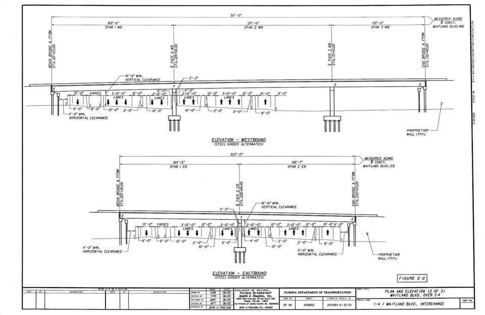
12 2.0 SUPERSTRUCTURE 2.1 Bridge Layout The proposed eastbound bridge will be constructed approximately 50 feet north of its current location. The new structure will be a two-span continuous bridge with an approximate length of 323 feet along the baseline of eastbound Maitland Boulevard. The span arrangement will be 164 feet 5 inches and 158 feet 7 inches. The bridge has a constant roadway width of 87 feet 1 inch. The bridge will carry five lanes of traffic with 12-foot shoulders on each side. All lanes and shoulders of I-4, Ramp B, and Ramp D1 will be spanned by the proposed structure. It is necessary to place Pier 2 in the median of the Ultimate I-4. The District has given a directive that the Special Use Lanes (SUL) and General Use Lanes (GUL) of I-4 in each direction shall be contiguous with 12-foot wide full depth shoulders. This will allow flexibility in the Ultimate I-4 Section to go from three GUL, two 12-foot shoulders, and two SUL to a seven GUL Section. This directive essentially rules out locating any substructure units between the SUL and GUL. Spans 1 and 2 will each carry traffic over three 12-foot GUL, two 12-foot shoulders, and two 12-foot wide SULs. The depth of the superstructure is limited by the unique vertical geometry of the Maitland Boulevard/I-4 interchange. Both eastbound and westbound Maitland Boulevard profiles are restricted by vertical clearances related to the Ramp C1 and Ramp A1 underpasses (separate structures) as well as the I-4 travel lanes. Ramp B and Ramp D1, which pass under the Maitland Boulevard over I-4 Bridge, do not control the Maitland Boulevard profile. The maximum superstructure depth given these constraints is approximately 7 feet 4 inches. The point of minimum vertical clearance is on the inside edge of eastbound SUL. This depth provides the necessary vertical clearance of 16 feet 6 inches for all travel lanes. Standard bridge traffic barriers will be used on both sides of the bridge. Proprietary walls will be needed at the beginning and end of the bridge to maintain the fill for the grade separation. See Figure 2-1, Figure 2-2 and Figure 2-3 for the plan and elevation of the proposed bridge. 2.2 Superstructure Alternatives An effective superstructure balances both span limitation of beams and beam spacing. However, structure depth limits can often control and limit some superstructure options. Four superstructure alternatives will be efficient for the maximum 164-foot-5 inch span length and will have structure depth of less than 7 feet 4 inches. Florida Bulb-T 72 Spliced Girder Cast-in-Place Concrete Box Girder Steel Plate Girder Steel Box Girder Interstate 4 Interchange at Maitland Boulevard 2-1 Bridge Development Report Eastbound Maitland Boulevard over I-4 Chapter 6

13

14
15

16 2.2.1 Alternative 1 Florida Bulb-T 72 Spliced Girders Spliced concrete girders with main spans in excess of 220 feet have been successfully used on many bridges in Florida. The required span lengths are well within the capabilities of this type of superstructure. Cost savings is the primary advantage of using post-tensioned Florida Bulb-T (FBT) 72 spliced girders. The main span unit will consist of nine precast, prestressed FBT 72 girders made continuous through the use of post-tensioning tendons anchored and stressed at both ends of the unit with an 8½-inch cast-in-place concrete deck. Precast segments over the piers will have an approximate length of 59 feet. The flanking span segments will have approximate lengths of 134 feet and 128 feet accordingly. 1-foot closure pours will be cast-in-place during construction at the interface of the precast sections. Cantilevered sections at the interior pier will be supported on temporary supports (falsework) located in Span 1. This falsework will be located on one side of the pier section away from the existing travel lanes for support until the other segments are constructed. The preliminary design documentation for the FBT 72 spliced girder alternative is included in Appendix C and a typical section is shown in Figure 2-4. Initially, an alternative with two simple spans using FBT 78 was also considered. However, it would have resulted in span lengths up to 164 feet 6 inches (±). At these span lengths the limit of allowable prestress is reached. Also, transport of concrete beams this long is a major undertaking. Because of these reasons, FDOT District 5 has advised against recommending the FBT 78 for simple spans of similar length in the recent past Alternative 2 CIP Concrete Box Girder A cast-in-place (CIP) concrete box girder can be utilized to create an efficient superstructure that meets the span length and curvature requirements of the new structure. Aesthetics is the primary advantage of a cast-in-place superstructure. A major disadvantage of CIP construction is the high cost of formwork and falsework. Additional consideration is also given to maintenance of traffic because of the need for formwork and falsework over existing lanes of traffic. A constant depth CIP concrete box girder alternative was developed as a viable alternative for the eastbound Maitland Boulevard over I-4 bridge given the span lengths and the needed structure depth. Since the eastbound and westbound Maitland Boulevard bridge over I-4 will be constructed in phases, opportunities exist for the reuse of formwork and falsework. The westbound structure will have the same depth and cross section as the majority of the eastbound bridge. See Chapter 7 for the similar typical sections of Westbound Maitland Boulevard over I-4. A comprehensive effort was made to estimate the costs associated with the construction of this alternative beyond a more expensive unit cost of concrete. Temporary substructure elements for support piers were included in the estimated costs for this alternative. These piers are needed for the falsework that support the formwork over I-4 traffic. Interstate 4 Interchange at Maitland Boulevard 2-5 Bridge Development Report Eastbound Maitland Boulevard over I-4 Chapter 6

17

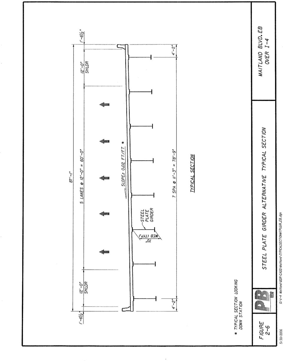
18 The primary features of the CIP concrete box girder alternative are summarized below: Constant depth box Similar cross section for both Maitland Boulevard bridges over I-4 The preliminary design documentation for the CIP Concrete Box girder alternative is included in Appendix C and a typical section is shown in Figure 2-5. Recently, the long-term performance of post-tensioned bridges has been called into question due to corrosion problems. It has been recognized that the procedures, specifications, materials, and inspection of the grouting operation have been insufficient. The FDOT has been proactive in both the identification of the problems and the development of solutions associated with post-tensioning systems. Due to the inland location of the Maitland Boulevard bridges, the changes to the Structures Design Guidelines, and grouting specifications, the long-term performance of the posttensioning system should be consistent with the performance of the other superstructure alternatives examined in this report Alternative 3 Steel Plate Girders Curved steel plate girders can be readily designed and constructed to meet the requirements of the new structures. The cross section of the bridge allows a beam spacing of 11 feet 3 inches. Exterior deck cantilevers are only 4 feet 2 inches to reduce the load on the exterior girder. Flange thickness is varied to optimize the girder section throughout its length. The plate girder alternative utilizes eight girders with an 8½-inch cast-in-place concrete deck. Girders will utilize Grade 50 structural steel in all regions with A36 steel used for the cross-bracing. The girders will be horizontally curved. The web depth of 70 inches (5 feet 10 inches) provides a maximum span to web depth ratio of Maximum flange plate sizes were 22 inches x 1 3/8 inches over Pier 2. The preliminary design documentation for the plate girder alternative is included in Appendix C and a typical section is shown in Figure Alternative 4 Steel Box Girders Steel box girders offer improved aesthetics over the plate girders. The principal disadvantages of steel box girders are the increased complexity of detailing and fabrication. The FDOT BDR Cost Estimating Guidelines recommend increasing the cost for structural steel by approximately 20 percent for steel box girders. The typical section for the Maitland Boulevard over I-4 bridges is ideal for steel box girders. Since both steel alternatives have eight webs, a superstructure section utilizing four box girders results in an efficient structure similar in steel quantity to the plate girder alternative. Interstate 4 Interchange at Maitland Boulevard 2-7 Bridge Development Report Eastbound Maitland Boulevard over I-4 Chapter 6

19

20
21 Improved aesthetics is the most important attribute of the steel box girders. The continuous lines of the bottom soffit will accentuate the slight curvature of the bridge alignment. FDOT-District 5 has generally recommended using box girders for curved structures in locations that call for higher aesthetic standards. On a similar project (I-4/SR 408 Interchange), the District and the City of Orlando/Orange County Aesthetics Committee agreed on using steel box girders superstructure for all curved bridges over I-4. The steel box girder alternative utilizes four boxes with an 8½-inch cast-in-place concrete deck. Boxes will utilize Grade 50 structural steel in all regions with A36 steel used for the internal-bracing, end diaphragms and pier diaphragms. The ideal web depth is 72 inches (6 feet) that provides a maximum span to web depth ratio of 27.4 creating a slender attractive superstructure. Maximum flange plate sizes were 94 inches x 7/8 inches over the interior pier. The thickest top flange of 18 inches x 2¼ inches is also at this location. The preliminary design documentation for the plate girder alternative is included in Appendix C. The superstructure cross section developed for the steel box girder alternative is shown in Figure Miscellaneous Superstructure Details Expansion Joints Due to the insignificant curvature of the superstructure, the movement of the superstructure will be along girder lines. Expansion joints will only be provided at the end bents to reduce maintenance and construction costs Steel Girder Alternatives Strip seal expansion joints can be designed to accommodate the movements for the steel girder. The maximum joint movements should be within 2 inches, making strip seals the logical choice FBT 72 Spliced Girder and CIP Concrete Box Girder Alternatives In addition to thermal movements, the joints for the cast-in-place concrete box girder alternative must be detailed to accommodate movements created by long-term creep and shrinkage of the post-tensioned superstructure. Strip seal type joints should handle the expected movement of 2 inches Bearings All alternatives will require elastomeric bearings at the end bents. The steel girder alternatives will require pot bearings at the piers. The FBT 72 spliced girder alternative will use elastomeric bearings at the pier. The CIP concrete box girder alternative does not need any bearings at the pier due to integral superstructure-to-column connection. Interstate 4 Interchange at Maitland Boulevard 2-10 Bridge Development Report Eastbound Maitland Boulevard over I-4 Chapter 6
22
23 Bearing Replacement Bearing replacement at the end bents will be facilitated by jacking between the bearings in the CIP concrete box girder and FBT 72 spliced girder alternatives and underneath the girders in front of the bearings for the steel superstructure alternatives. For the steel alternatives, pot bearings at piers can be replaced, jacking the steel box girders on either side of the column using falsework in the roadway shoulder area Deck Drainage Spread calculations indicate that a bridge deck drainage system is not required. Inlets that will carry the water from the bridge surface to drainage pipes located beneath the proprietary walls will be provided adjacent to each end bent. Interstate 4 Interchange at Maitland Boulevard 2-12 Bridge Development Report Eastbound Maitland Boulevard over I-4 Chapter 6
24
25 3.0 SUBSTRUCTURE 3.1 Columns Maximum column dimensions are limited to 5 feet at Pier 2 based on the location in the median and the minimum shoulder width. The FBT 72 Spliced Girder Alternative will use 5-foot square columns with rustications. The steel girder alternatives use similar 4-foot square columns. An advantage of thinner columns is that the adjacent I-4 SUL inside shoulders can realize their full typical width of 4 feet 6 inches. The CIP concrete box alternative will use a 5-foot diameter column under each box. 3.2 Geotechnical The preliminary geotechnical investigation consisted of multiple Standard Penetration Test (SPT) borings. The boring logs and preliminary analysis are included in the preliminary Geotechnical Report. The borings identified a pile end-bearing layer consisting of medium dense to very dense silty fine sand. Depending on the location, this layer was encountered between Elevations +22 feet NAVD to Elevation -15 feet NAVD, at which depth the boring was ended. The preliminary Geotechnical Report recommends driven pile foundations and an elevation of +5 feet NAVD to -4 feet NAVD for pile tip. Drilled shafts are not considered a better solution compared to pile foundations. The preliminary SPT borings were analyzed using the FDOT pile capacity program SPT 97. The maximum ultimate bearing capacity (UBC) was limited by the soil conditions encountered in the borings. Table 3-1 identifies foundation types that were investigated for the I-4/Maitland Boulevard interchange project. This table uses Elevation +0 feet as an average pile tip elevation for this bridge. Table 3-1 Alternative Foundation Types Description Unit Unit Cost Anticipated Length (ft) UB C (To ns) Cost to Capacity Ratio ($/Ton) Concrete Piling Prestressed (18" Sq.) LF $ Concrete Piling Prestressed (24" Sq.) LF $ Concrete Piling Prestressed (30" Sq.) LF $ Steel Piling (HP 12 X 53 ) LF $ Steel Piling (HP 14 X 89 ) LF $ Steel Piling (16-inch Dia. Pipe) LF $ Steel Piling (20-inch Dia. Pipe) LF $ Interstate 4 Interchange at Maitland Boulevard 3-1 Bridge Development Report Eastbound Maitland Boulevard over I-4 Chapter 6
26 inch, 24-inch, and 30-inch Prestressed Concrete Piles Square prestressed concrete piles are commonly used for bridge construction in Florida. These piles offer proven performance and are economically produced by several prestressed concrete producers in Florida. Square prestressed concrete piles are difficult to splice and produce vibrations when driven (same for all displacement piles). In locations where there is limited space or when the piles need to be driven near existing structures square prestressed concrete piles may not be a viable option. Since neither location has these constraints, square prestressed concrete piles are a suitable foundation site Steel H-piles The geotechnical report also evaluated HP 12 x 53 and HP 14 x 89 for their suitability at this location. The steel H-piles are considered favorable in supporting relatively high compressive loads for end bearing when hard, sound limestone/mudstone, dense sands, or consolidated clay soils are encountered at depth. As shown in Table 3-1, the HP 12 x 53 and HP 14 x 89 are not economical due to higher cost and lower capacities. Steel H-piles were not given further consideration in this report Steel Pipe Piles The Geotechnical Report also evaluated steel pipe piles for their suitability at this location. The 16-inch and 20-inch steel pipe piles are easy to splice As shown in Table 3-1, the 16-inch and 20-inch steel pipe piles are not economical due to higher cost and lower capacities. Steel pipe piles were not given further consideration in this report. 3.3 Pile Evaluation It is accepted practice to use the same foundation type for all piers and end bents of the same bridge. The need for different pile hammers adds unnecessary expense to pile driving operations. Preliminary foundation designs were completed to determine the most efficient foundation system. Table 3-2 shows the cost comparison between 18-inch piles and 24-inch square prestressed concrete piles with the 24-inch pile being the more economical choice. Therefore, the preferred foundation alternative is 24-inch prestressed concrete piles. Pile layouts for 24-inch prestressed concrete piles for all superstructure alternatives are shown in Figure 3-1 and Figure 3-2. Interstate 4 Interchange at Maitland Boulevard 3-2 Bridge Development Report Eastbound Maitland Boulevard over I-4 Chapter 6
27 Pay Item Number Table 3-2 Substructure Cost Comparison (Spliced Girder Alternative) Pile and Pile Cap Comparison Table for Pier 2 Pile Cap Description Unit Unit Price Quantity Subtotal 18-inch Piles with a 23'-0" x 70'-0" Pile Cap Concrete Class IV (Mass Substructure) Reinforcing Steel (Substructure) CY $ $ 93, LB $ $ 26, Concrete Piling (18-inch) LF $ $ 188, Test Piles (18-inch) LF $ $ 17, Test Load (Dynamic) EA $ $ 2, Cofferdam (Temporary Sheet Piles) 24-inch Piles with a 17'-0" x 70'-0" Pile Cap Concrete Class IV (Mass Substructure) Reinforcing Steel (Substructure) SF $ $ 48, Total $375, CY $ $ 69, LB $ Concrete Piling (24-inch) LF $ Test Piles (24-inch) LF $ Test Load (Dynamic) EA $ Cofferdam (Temporary Sheet Piles) SF $ $ 19, $ 166, $ 18, $ 2, $ 45, Total $ 321, Interstate 4 Interchange at Maitland Boulevard 3-3 Bridge Development Report Eastbound Maitland Boulevard over I-4 Chapter 6
28
29
30 3.4 End Bents Soil reinforcement will be used on the end bent backwalls to restrict overturning soil forces and horizontal superstructure loads. A minimum end bent cap width of 4 feet is required for jacking the superstructure for replacement of bearing pads. The preliminary design steel girder alternatives consists of a 4-foot wide by 3-foot 6-inch thick pile cap with eight piles. The preliminary design for the CIP concrete box girder alternative consists of a 4-foot wide by 3-foot 6-inch thick pile cap with ten piles. The preliminary design for the FBT 72 spliced girder alternative consists of a 4-foot wide by 3-foot 6-inch thick pile cap with nine piles. The preliminary design documentation is included in Appendix C. 3.5 Footings The footer width is limited so eastbound I-4 traffic can be maintained while the footer is constructed, see Section 5 for further details. A footing for Pier 2 was designed for the spliced girder and steel girder superstructure alternatives. A single large 5-foot thick concrete footing with a three by eleven pile configuration of 24-inch prestressed concrete piles handles all of the superstructure loads and provides the necessary space needed to maintain traffic for the spliced girder and steel alternatives. A 5-foot 6-inch thick footer with a four by four 24-inch prestressed concrete pile configuration at each column is adequate for Pier 2 for the CIP Box Girder alternative. See Figure 3-1 and Figure 3-2 for the footer plan and elevations. 3.6 Piers Piers are required based on the previous superstructure discussions. It was decided to use a multi-column pier as shown on the renderings submitted to the District and aesthetics committee Steel Girder and FBT 72 Spliced Girder Alternatives The Steel Girder and FBT 72 alternatives will use a standard multi-column pier supported on pile footings. The depth of the pier cap will taper between the columns for heightened aesthetics. See Figure 7-1, Figure 7-3, and Figure 7-4 for elevation views of this pier with each superstructure alternative CIP Concrete Box Girder Alternative A major advantage of the cast-in-place concrete box alternative is that pier caps are not required. Internal diaphragms will be provided to transmit the reactions from the superstructure to the columns. See Figure 7-2 for an elevation view of this pier. Interstate 4 Interchange at Maitland Boulevard 3-6 Bridge Development Report Eastbound Maitland Boulevard over I-4 Chapter 6
31 3.7 Foundation Constructability Given the soils encountered in the preliminary geotechnical investigation, 24-inch prestressed piles are expected to be readily installed by experienced bridge contractors. Their modest weight and UBC enables these piles to be transported, lifted and driven by commonly available construction equipment. Noise and vibrations can be reduced by preforming and bagging the pile that involves wrapping the hammer and pile in an insulated shroud. Interstate 4 Interchange at Maitland Boulevard 3-7 Bridge Development Report Eastbound Maitland Boulevard over I-4 Chapter 6
32
33 4.0 COST ESTIMATE Preliminary quantities were calculated for each superstructure alternative. These quantities were then multiplied by unit prices to estimate the superstructure cost for each alternative. The quantity calculations are included in Appendix A. 4.1 Unit Costs (BDR Cost Estimating Guidelines) During the corridor-wide structures coordination meeting on March 1, 2005, it was decided that unit costs from the January 2004 Structures Design Guidelines, BDR Cost Estimating Section would be used, and supplemented when necessary by FDOT pay item cost history data. The primary goal of developing costs for the BDR was to identify the relative costs between various alternatives using the BDR Cost Estimating unit prices. 4.2 Other Costs The BDR Cost Estimating Guidelines gives a method to measure the relative construction cost of each alternative. The guidelines do not take into account the maintenance costs associated with particular bridge superstructure types or costs to the public due to travel delays during construction. While these costs are not quantified in this report, it should be noted CIP concrete box and FBT 72 spliced girder superstructures have lower average maintenance costs over the life span of the bridge than steel girder superstructures. The CIP concrete box girder superstructure will result in more traffic delays and associated costs due to the constricted opening under the falsework. 4.3 Cost Summary The total estimated construction cost of the bridge for the four alternatives with aesthetic treatments is: Alternative 1 FBT 72 Spliced Girder $3,916,000 Alternative 2 CIP Concrete Box $4,401,000 Alternative 3 Steel Plates $4,307,000 Alternative 4 Steel Box $4,177,000 Table 4-1 itemizes the estimated construction cost for the four alternatives. Interstate 4 Interchange at Maitland Boulevard 4-1 Bridge Development Report Eastbound Maitland Boulevard over I-4 Chapter 6
34 Maitland Blvd. over I-4 FPID Estimated Quantities for BDR Table 4-1 Estimated Construction Cost for Eastbound Maitland Boulevard over I-4 Pay Item Description Unit Unit Price Quantity Subtotal Quantity Subtotal Quantity Subtotal Quantity Subtotal Number Additional Costs Alternative 1 FBT 72 Spliced Girder Alternative 2 CIP Concrete Box Girder Alternative 3 Steel Plate Girders Alternative 4 Steel Box Girders Structures, Removal of Existing SF $ $ 320, $ 320, $ 320, $ 320, Conc Class II (Approach Slabs)(2 req.) CY $ $ 48, $ 48, $ 48, $ 48, Reinforcing Steel (Approach Slabs) LB $ $ 19, $ 19, $ 19, $ 19, Aesthetic Treatments on Bridge* SF $ $ 398, $ $ 414, $ - Total Additional Cost = $ 787, $ 388, $ 803, $ 388, Superstructure Class IV Concrete (Superstructure) CY $ $ 313, $ $ 313, $ 313, Class IV Concrete (CIP Superstructure) CY $ $ 57, $ 1,398, $ $ Reinforcing Steel (Superstructure) LB $ $ 76, $ 152, $ 69, $ 69, Bridge Floor Grooving SY $ $ 8, $ 8, $ 8, $ 8, Composite Neoprene Bearing Pads CF $ $ 6, $ 3, $ 7, $ 5, Prestressed Beams (Bulb-T)(72)(Modified) LF $ $ 523, $ $ $ Post-tensioning Strands (Transverse) LB $ $ $ 55, $ - 0 $ Post-tensioning Strands (Longitudinal) LB $ $ 124, $ 145, $ - 0 $ Multirotational Bearing Assembly (F&I) ( Kips) EA $ 5, $ - 0 $ - 0 $ - 4 $ 22, Struct Steel (Carbon) LS(LB) $ $ - 0 $ $ 65, $ 68, Struct Steel (Low Alloy) (Plates) LS(LB) $ $ - 0 $ $ 901, $ Struct Steel (Low Alloy) (Boxes) LS(LB) $ $ - 0 $ - 0 $ $ 1,206, Expansion Joint Seal LF $ $ 17, $ 17, $ 17, $ 17, Traffic Railing Barrier (32" F-shape) LF $ $ 33, $ 33, $ 33, $ 33, Total Superstructure Cost = $ 1,163, $ 1,815, $ 1,418, $ 1,746, Substructure - per End Bent Concrete Class IV (Substructure) CY $ $ 36, $ 36, $ 36, $ 36, Reinforcing Steel (Substructure) LB $ $ 4, $ 4, $ 4, $ 4, Concrete Piling (24 in) LF $ $ 52, $ 58, $ 45, $ 45, Concrete Test Piles (24 in) LF $ $ 21, $ 21, $ 21, $ 21, Test Load (Dynamic) EA $ 2, $ 2, $ 2, $ 2, $ 2, Cost Per End Bent = $ 116, $ 123, $ 110, $ 110, Number of End Bents = End Bent Total = $ 233, $ 246, $ 220, $ 220, Substructure - per Pier Concrete Class IV (Substructure) CY $ $ 37, $ 19, $ 37, $ 37, Concrete Class IV (Mass) (Substructure) CY $ $ 100, $ 67, $ 100, $ 100, Reinforcing Steel (Substructure) LB $ $ 34, $ 22, $ 34, $ 34, Concrete Piling (24 in) LF $ $ 166, $ 161, $ 166, $ 166, Concrete Test Piles (24 in) LF $ $ 18, $ 18, $ 18, $ 18, Test Load (Dynamic) EA $ 2, $ 2, $ 2, $ 2, $ 2, Post-tensioning Strands LB $ $ - 0 $ - 0 $ - 0 $ Cofferdam (Temporary sheet piles) SF $ $ 45, $ 51, $ 45, $ 45, Cost Per Pier = $ 405, $ 342, $ 405, $ 405, Number of Piers = Pier Total = $ 405, $ 342, $ 405, $ 405, Total Bridge Cost = $ 1,802, $ 2,405, $ 2,044, $ 2,373, Cost per Sq. ft = $ $ $ $ Total Bridge Cost (With Additional Cost)= $ 2,589, $ 2,794, $ 2,847, $ 2,761, Cost per Sq. ft (With Additional Cost) = $ $ $ $ Contingencies(25%) = $ 647, $ 698, $ 711, $ 690, Subtotal = $ 3,236, $ 3,492, $ 3,559, $ 3,452, Urban Construction (6%) = $ 194, $ 209, $ 213, $ 207, Construction over Traffic (20% for CIP Box 15% for steel and FBT Spliced Girder )= $ 485, $ 698, $ 533, $ 517, Grand Total Without Aesthetic Treatments = $ 3,313, $ 4,400, $ 3,680, $ 4,177, Grand Total = $ 3,916, $ 4,400, $ 4,307, $ 4,177, Cost per Sq. ft (Grand Total) = $ $ $ $ * Optional Cost for Aesthetic Treatments on Bridge **MOT and Mobilization Costs are not included in this estimate 6/8/ of 1 Maitland EB over I-4 Cost\Summary
35
36 5.0 TRAFFIC CONTROL Traffic control is a major element in the successful construction of the I-4/Maitland Boulevard interchange. All alternatives will use the same proposed traffic phasing to construct the bridge carrying Maitland Boulevard (eastbound) over I-4. Construct temporary pavement for I-4 (eastbound) to the immediate east of existing pavement (Phase I Stage 1). Shift I-4 (eastbound) traffic to east to create room for construction of foundations and piers for both bridges carrying Maitland Boulevard over I-4. Then, construct piers for Maitland Boulevard bridges (eastbound and westbound) over I-4 (Phase I Stage 2). Construct westbound Maitland Boulevard over I-4 Bridge (Phase II Stages 3 and 4). Shift westbound Maitland Boulevard traffic from existing bridge to the new westbound bridge and demolish existing westbound bridge (Phase III Stage 1). Construct new eastbound Maitland Boulevard over I-4 Bridge (Phase III Stage 2). Shift eastbound Maitland Boulevard traffic to the new bridge (Phase III Stage 3). Demolish existing bridge (Phase IV Stage 3). 5.1 Foundation Construction The traffic control required to construct the end bents and piers will be the same for all alternatives. Construction areas required to construct the foundations will be provided in the maintenance of traffic scheme. This will also create a lay-down area for piling as well as provide room for the necessary construction equipment. See Figure 5-1 for a detail of lane shifts and construction area. Foundation construction should not impact Maitland Boulevard traffic since it is carried by existing structures that are an adequate distance away. 5.2 FBT 72 Spliced Girder Alternative Falsework will support girder segments as they are erected. Rolling roadblocks will be required when beams are set and the cast-in-place concrete deck is poured over the I-4 travel lanes. Section 6 shows the expected location of the falsework required to support the FBT 72 pier section. Girder erection will be accomplished using ground cranes. Interstate 4 Interchange at Maitland Boulevard 5-1 Bridge Development Report Eastbound Maitland Boulevard over I-4 Chapter 6
37
38 5.3 CIP Concrete Box Superstructure Construction Overhead formwork supported by temporary falsework spanning I-4 traffic is required for this alternative. The conceptual scheme for the formwork is shown in Section 6. Construction of the falsework and formwork over traffic will be restricted to nighttime hours to reduce traffic delays. The proposed erection scheme for the eastbound Maitland Boulevard bridge over I-4 utilizes proven techniques that have been used in other parts of the country for cast-inplace concrete box bridges over traffic. Vertical clearance during construction was checked since an additional depth of 2 feet will be needed to build this alternative over I- 4 traffic. The proposed I-4 mainline cross section is about 2 feet higher than the existing I-4 cross section. This effectively adds 2 feet of extra clearance under the proposed superstructure during construction since the structures will be constructed over the existing I-4. The major disadvantage of this alternative is the limited roadway width under the formwork. Temporary columns close to traffic will be needed to support falsework beams. These beams will span over I-4 traffic to support the superstructure formwork. The temporary roadway typical section, consisting of one 12-foot lane, two 11-foot lanes and two 2-foot shoulders, will shorten the falsework span and reduce the beam depth but will also impair traffic flow. An extra 2 feet behind the traffic barriers will be used to further protect the temporary piers that will be founded on steel pipe piles. It is necessary to minimize the depth of the steel support beams over traffic to maintain vertical clearance over I-4. The current concept calls for at least 16 feet of vertical clearance to the temporary girders that support the formwork, which is consistent with FDOT PPM, Chapter 2 requirements. 6 inches of additional clearance, intended to accommodate future resurfacing, need not be provided during the construction stage. 5.4 Steel Superstructure Construction The steel erection will be accomplished using ground cranes. The cranes will be located adjacent to the superstructure in the median or east or west of the I-4 travel lanes. Additionally, traffic will not be permitted beneath the position of the superstructure where deck concrete is being placed. The use of nighttime rolling roadblocks along I-4 will be used to create construction windows to pour the deck and place the girders. Construction during off-hours will mitigate inconveniences to the public. This type of construction is standard with steel girder bridge alternatives. Interstate 4 Interchange at Maitland Boulevard 5-3 Bridge Development Report Eastbound Maitland Boulevard over I-4 Chapter 6
39
40 6.0 CONSTRUCTABILITY 6.1 Foundations The constructability of the foundations is equivalent for all alternatives. Driving prestressed concrete piles is considered standard bridge construction. Given the adequate lay-down area adjacent to the end bents, the delivery and storage of material will not be a significant issue. 6.2 Superstructure Florida Bulb-T 72 Spliced Girders Falsework will support the pier girder section in locations away from traffic until the end girder sections are spliced. Steel strongbacks will aid in connecting these two sections until the last section over the main span can be dropped in and closure pours cast. The spliced beams will be post-tensioned in two stages and use three 3½-inch ducts each containing twelve 0.6-inch strands. The post-tensioning tendons will be stressed before construction of the end bent backwalls. See Figure 6-1 for the construction sequence CIP Concrete Box Girders The principal challenge for the CIP concrete box girder alternative is to span the existing lanes of I-4 with temporary falsework, while maintaining the necessary minimum vertical clearance (16 feet based on AASHTO and PPM requirements when resurfacing/overlay is not expected). The alignment of I-4 relative to the proposed eastbound Maitland Boulevard alignment makes these falsework spans approximately 50 feet over both westbound and eastbound I-4. The temporary steel support beams and most of the formwork can be reused from the westbound Maitland Boulevard structure. See Figure 6-2 for the falsework concept for the CIP concrete box alternative Steel Girder Alternatives Common construction methods for continuous steel girder bridges will be used to erect the bridge superstructure. The lack of post-tensioning, as well as a lack of any falsework requirements for CIP concrete box construction, will speed the construction of these alternatives. Interstate 4 Interchange at Maitland Boulevard 6-1 Bridge Development Report Eastbound Maitland Boulevard over I-4 Chapter 6
41
42
43
44 7.0 AESTHETICS The Maitland Boulevard bridges over I-4 will be highly visible due to the large traffic volume passing beneath the structures from one of the busiest transportation corridors in the state. The FDOT and design team are committed to providing attractive yet costeffective features to enhance the immediate surroundings. It is generally accepted that the overall form of the structure has the most significant impact on aesthetics. Fortunately, the shape and curvature of the new bridges will create an inherently attractive structure. The column shape is controlled by roadway shoulder constraints. The proposed circular columns of the CIP concrete box girder alternative will blend well with the subtle overall curves of the structure provided by the horizontal and vertical geometry of the bridge alignment. The CIP concrete box alternative will have one less column than the other alternatives. This alternative also will not require pier caps since these are integral with the box. The piers required for the steel girder and FBT 72 spliced girder alternatives will use elements from the FDOT preferred details to enhance the aesthetics of the substructure. The pier cap will vary in height between the columns and use a radius on the bottom to further the curve motif of the bridges. See Figure 7-1 through Figure 7-4 for a conceptual example of a proposed pier with each superstructure alternative. FDOT has an option to add fiberglass reinforced plastic panels or precast concrete fascia panels to the fascia on the FBT 72 spliced girders and steel plate girder alternatives to improve aesthetics. Fiberglass reinforced plastic panels can be molded into many different shapes and use a variety of surface finishes. Figure 7-7 shows a rendering of the fiberglass reinforced panel configuration proposed for the FBT 72 spliced girders and steel plate girder alternatives. Long term maintenance for the fiberglass reinforced plastic panels must be considered when developing details. Connections made between panels and to the structure need to be designed not to corrode or become loose. Columns and superstructure elements will receive either a Class V or concrete stain finish. The color and texture of the finish will be selected after coordinating with the architect and the project aesthetics committee. The preliminary concept for the proprietary walls is to have a recessed diamond finish. Steel box girders are preferred over the plate girders because of the smooth bottom soffit and uncluttered appearances. The box girders have discontinuities in the form of end cross frames. The simple form of cast-in-place concrete box girders offers improved aesthetics to steel plate, steel box girder, and FBT 72 spliced girder bridges. The large overhangs, smooth bottom soffit and modest substructures create a series of smooth lines that follow the alignment of the bridge. Figure 7-5 and Figure 7-6 show examples of each superstructure type. Interstate 4 Interchange at Maitland Boulevard 7-1 Bridge Development Report Eastbound Maitland Boulevard over I-4 Chapter 6
Safe & Sound Bridge Terminology
 Safe & Sound Bridge Terminology Abutment A retaining wall supporting the ends of a bridge, and, in general, retaining or supporting the approach embankment. Approach The part of the bridge that carries
The unit costs are based on the trend line of the 3 low bids for the average quantity.
 Page 1 of 8 COST ESTIMATE GENERAL INSTRUCTIONS The unit costs are based on the trend line of the 3 low bids for the average quantity. Apply the Unit Costs to ordinary structures. Unit Costs should generally
3.1 Historical Considerations
 3. Recommended Scope of Bridge improvements 3.1 Historical Considerations In the fall of 2000, an outside consultant, Fraser Design, suggested that the existing 4 th St. Bridge is potentially eligible
Bridge Type Selection
 Bridge Type Selection The major consideration for bridge type selection for bridges on the State Aid system is initial cost. Future maintenance costs, construction time, and location are considered when
Micropiles Reduce Costs and Schedule for Merchant RR Bridge Rehabilitation
 Micropiles Reduce Costs and Schedule for Merchant RR Bridge Rehabilitation Jeff R. Hill, P.E. Hayward Baker Inc. 111 W. Port Plaza Drive Suite 600 St. Louis, MO 63146 314-542-3040 JRHill@HaywardBaker.com
IH-635 MANAGED LANES PROJECT, SEG. 3.2
 IH-635 MANAGED LANES PROJECT, SEG. 3.2 Location: Dallas, Texas Owner: Texas Department of Transportation Client: Ferrovial Agroman Construction Cost: $1 Billion Construction Completion Date: December,
CHAPTER 9 LONG TERM MONITORING AT THE ROUTE 351 BRIDGE
 CHAPTER 9 LONG TERM MONITORING AT THE ROUTE 351 BRIDGE 9.1 INTRODUCTION An important reason that composite piles have not gained wide acceptance in the civil engineering practice is the lack of a long
Challenging Skew: Higgins Road Steel I-Girder Bridge over I-90 OTEC 2015 - October 27, 2015 Session 26
 2014 HDR Architecture, 2014 2014 HDR, HDR, Inc., all all rights reserved. Challenging Skew: Higgins Road Steel I-Girder Bridge over I-90 OTEC 2015 - October 27, 2015 Session 26 Brandon Chavel, PhD, P.E.,
TECHNICAL SPECIFICATION SERIES 8000 PRECAST CONCRETE
 TECHNICAL SPECIFICATION SERIES 8000 PRECAST CONCRETE TECHNICAL SPECIFICATION PART 8000 - PRECAST CONCRETE TABLE OF CONTENTS Item Number Page 8100 PRECAST CONCRETE CONSTRUCTION - GENERAL 8-3 8101 General
Value Engineering vs. Alternate Designs in Bridge Bidding
 Value Engineering vs. Alternate Designs in Bridge Bidding Compares the advantages and disadvantages of alternate designs and value engineering in bidding of bridges as experienced in the State of Florida.
4B-2. 2. The stiffness of the floor and roof diaphragms. 3. The relative flexural and shear stiffness of the shear walls and of connections.
 Shear Walls Buildings that use shear walls as the lateral force-resisting system can be designed to provide a safe, serviceable, and economical solution for wind and earthquake resistance. Shear walls
Up-Down Construction Utilizing Steel Sheet Piles and Drilled Shaft Foundations
 Up-Down Construction Utilizing Steel Sheet Piles and Drilled Shaft Foundations Nathan A. Ingraffea, P.E., S.E. Associate, KPFF Consulting Engineers, Portland, Oregon, USA Abstract The use of steel sheet
Index 20010 Series Prestressed Florida-I Beams (Rev. 07/12)
") Index 20010 Series Prestressed Florida-I Beams (Rev. 07/12) Design Criteria AASHTO LRFD Bridge Design Specifications, 6th Edition; Structures Detailing Manual (SDM); Structures Design Guidelines (SDG)
Index 20010 Series Prestressed Florida-I Beams (Rev. 07/12) Design Criteria AASHTO LRFD Bridge Design Specifications, 6th Edition; Structures Detailing Manual (SDM); Structures Design Guidelines (SDG)
US 51 Ohio River Bridge Engineering and Environmental Study
 US 51 Ohio River Bridge Engineering and Environmental Study ITEM NOS. 1-100.00 & 1-1140.00 Prepared by: Michael Baker Jr., Inc. 9750 Ormsby Station Rd Louisville, KY 40223 August 16, 2013 Table of Contents
BRIDGE RESTORATION AND LANDSLIDE CORRECTION USING STRUCTURAL PIER AND GRADE BEAM
 BRIDGE RESTORATION AND LANDSLIDE CORRECTION USING STRUCTURAL PIER AND GRADE BEAM Swaminathan Srinivasan, P.E., M.ASCE H.C. Nutting/Terracon David Tomley, P.E., M.ASCE KZF Design Delivering Success for
USE OF MICROPILES IN TEXAS BRIDGES. by John G. Delphia, P.E. TxDOT Bridge Division Geotechnical Branch
 USE OF MICROPILES IN TEXAS BRIDGES by John G. Delphia, P.E. TxDOT Bridge Division Geotechnical Branch DEFINITION OF A MICROPILE A micropile is a small diameter (typically less than 12 in.), drilled and
FUTURE SLAB. PENETRATIONS and. DEMOLITION of POST-TENSIONED FLOORS
 FUTURE SLAB PENETRATIONS and DEMOLITION of POST-TENSIONED FLOORS 1.0 INTRODUCTION Post-tensioned floor slabs in Australia and South East Asia are now universally regarded as the most cost effective form
SPECIFICATIONS FOR PRECAST MODULAR BLOCK RETAINING WALL SYSTEM (revised 11/5/13)
") Page 1 of 7 STONE STRONG SYSTEMS SPECIFICATIONS FOR PRECAST MODULAR BLOCK RETAINING WALL SYSTEM (revised ) PART 1: GENERAL 1.01 Description A. Work includes furnishing and installing precast modular blocks
Page 1 of 7 STONE STRONG SYSTEMS SPECIFICATIONS FOR PRECAST MODULAR BLOCK RETAINING WALL SYSTEM (revised ) PART 1: GENERAL 1.01 Description A. Work includes furnishing and installing precast modular blocks
Chapter 3 Pre-Installation, Foundations and Piers
 Chapter 3 Pre-Installation, Foundations and Piers 3-1 Pre-Installation Establishes the minimum requirements for the siting, design, materials, access, and installation of manufactured dwellings, accessory
GLOSSARY OF TERMINOLOGY
 GLOSSARY OF TERMINOLOGY AUTHORIZED PILE LENGTHS - (a.k.a. Authorized Pile Lengths letter) Official letter stating Engineer's recommended length of concrete piles to be cast for construction of foundation.
FEBRUARY 2014 LRFD BRIDGE DESIGN 4-1
 FEBRUARY 2014 LRFD BRIDGE DESIGN 4-1 4. STRUCTURAL ANALYSIS AND EVALUATION The analysis of bridges and structures is a mixture of science and engineering judgment. In most cases, use simple models with
2015 ODOT Bridge Design Conference May 12, 2014. DeJong Rd Bridge High- Seismic Zone Case Study: Bridge Rehab vs. Replacement.
 2015 ODOT Bridge Design Conference May 12, 2014 DeJong Rd Bridge High- Seismic Zone Case Study: Bridge Rehab vs. Replacement Mary Ann Triska 2015 HDR, all rights reserved. Presentation Outline Project
How to Design and Build a Fence/G traverse Bridge or Graffiti Project
 Outline Project Location Project Description Project History Site Constraints Geotechnical Investigation & Soil Profile Foundation Design Process Photos Project Location Project Limits: The Grand River
Elevated Roads for Sri Lanka
 Elevated Roads for Sri Lanka M.T.R. Jayasinghe (Senior Professor, Structural Engineering, University of Moratuwa) Senior Professor M.T.R. Jayasinghe is a Professor of Structural Engineering, University
2006-2008 MHD BRIDGE SECTION WEIGHTED AVERAGE UNIT PRICES GUIDELINES FOR THE USE OF THE WEIGHTED AVERAGE UNIT PRICE TABULATION SHEETS
 2006-2008 MHD BRIDGE SECTION WEIGHTED AVERAGE UNIT PRICES GUIDELINES FOR THE USE OF THE WEIGHTED AVERAGE UNIT PRICE TABULATION SHEETS GENERAL 10/16/2008 The listed average unit prices are based on the
Rehabilitation of the Red Bank Road Bridge over Hoover Reservoir. Presented By: Doug Stachler, P.E.
 Rehabilitation of the Red Bank Road Bridge over Hoover Reservoir Presented By: Doug Stachler, P.E. Project Organization Owner Delaware County Engineers Office Design Consultant CH2M HILL Contractor Double
Emergency repair of Bridge B421
 Emergency repair of Bridge B421 over the Olifants River after fl ood damage INTRODUCTION AND BACKGROUND Bridge B421 is located on the R555 at km 5.03 on Section 01E between Witbank (now known as emalahleni)
Virginia Approach Spans
 Virginia Concrete Conference 2009 Woodrow Virginia Approach Spans David Tackoor, HNTB Formerly of URS Corp for Potomac Crossing Consultants Woodrow 1 Second Severn Crossing 2 Medway Crossing (Channel Tunnel
CONCRETE FLOOR SLAB & CASTING BED CONSTRUCTION
 CONCRETE FLOOR SLAB & CASTING BED CONSTRUCTION General 7 www.meadowburke.com 877-518-7665 MB1109 CONCRETE FLOOR SLAB AND CASTING BED CONSTRUCTION Quality Construction Begins at Ground Level Everything
Overhang Bracket Loading. Deck Issues: Design Perspective
 Deck Issues: Design Perspective Overhang Bracket Loading Deck overhangs and screed rails are generally supported on cantilever brackets during the deck pour These brackets produce an overturning couple
Prestressed Concrete I-Beam and TxGirder Haunch Design Guide
 Prestressed Concrete I-Beam and TxGirder Haunch Design Guide Components of the Haunch Camber: Camber is the upward deflection in the beam after release of the prestressing strands due to the eccentricity
High Strain Dynamic Load Testing of Drilled Shafts
 Supplemental Technical Specification for High Strain Dynamic Load Testing of Drilled Shafts SCDOT Designation: SC-M-712 (9/15) September 3, 2015 1.0 GENERAL This work shall consist of performing high-strain
Quality Control and Quality Assurance Guide
 Quality Control and Quality Assurance Guide Bridge Division, Design Section October 2013 Table of Contents Chapter 1 About this Guide... 3 Chapter 2 Goals and Objectives... 5 Chapter 3 Participants...
Design of Steel Structures Prof. S.R.Satish Kumar and Prof. A.R.Santha Kumar. Fig. 7.21 some of the trusses that are used in steel bridges
 7.7 Truss bridges Fig. 7.21 some of the trusses that are used in steel bridges Truss Girders, lattice girders or open web girders are efficient and economical structural systems, since the members experience
SUPPLEMENTAL TECHNICAL SPECIFICATIONS BI-DIRECTIONAL STATIC LOAD TESTING OF DRILLED SHAFTS
 July 14, 2015 1.0 GENERAL BI-DIRECTIONAL STATIC LOAD TESTING OF DRILLED SHAFTS This work shall consist of furnishing all materials, equipment, labor, and incidentals necessary for conducting bi-directional
STRUCTURES. 1.1. Excavation and backfill for structures should conform to the topic EXCAVATION AND BACKFILL.
 STRUCTURES 1. General. Critical structures may impact the integrity of a flood control project in several manners such as the excavation for construction of the structure, the type of foundation, backfill
MEMORANDUM. 1509 West Swann Avenue, Suite 225 Tampa, Florida 33606 Phone (813) 258-8818 Fax (813) 258-8525
 258-8818 Fax (813) 258-8525") 1509 West Swann Avenue, Suite 225 Tampa, Florida 33606 Phone (813) 258-8818 Fax (813) 258-8525 To: From: Date: Subject: Mr. Thomas Gibson, City of St. Petersburg Jeffrey D. Malyszek, PE and Deborah C.
1509 West Swann Avenue, Suite 225 Tampa, Florida 33606 Phone (813) 258-8818 Fax (813) 258-8525 To: From: Date: Subject: Mr. Thomas Gibson, City of St. Petersburg Jeffrey D. Malyszek, PE and Deborah C.
Design of Bridges. Introduction. 3 rd to 4 th July 2012. Lecture for SPIN Training at the University of Dar es Salaam
 Design of Bridges Introduction 3 rd to 4 th July 2012 1 FUNCTION OF A BRIDGE To connect two communities which are separated by streams, river, valley, or gorge, etc. 2 EVOLUTION OF BRIDGES 1. Log Bridge
Investigation of the November 2, 2013 collapse of concrete beams at Fort Lauderdale-Hollywood Airport runway project
 Investigation of the November 2, 2013 collapse of concrete beams at Fort Lauderdale-Hollywood Airport runway project U.S. Department of Labor Occupational Safety and Health Administration Directorate of
Chapter 2 Basis of design and materials
 Chapter 2 Basis of design and materials 2.1 Structural action It is necessary to start a design by deciding on the type and layout of structure to be used. Tentative sizes must be allocated to each structural
COLUMN-FREE OFFICE SPACE RISES IN CHICAGO S LOOP
 COLUMN-FREE OFFICE SPACE RISES IN CHICAGO S LOOP 30 x45 bay provides maximum tenant flexibility and increases leasing marketability By David E. Eckmann AIA, S.E. P.E. SURGING DEMANDS FOR RENTABLE OFFICE
SCHEMATIC AND PROJECT BUDGET APPROVAL EAST CAMPUS NURSING EDUCATION AND CLASSROOM
 Shepherd University Board of Governors June 9, 2005 Agenda Item No. 9 SCHEMATIC AND PROJECT BUDGET APPROVAL EAST CAMPUS NURSING EDUCATION AND CLASSROOM In 1994 construction began on the Byrd Science and
Residential Decks. Planning and Development Services Department
 Building Safety Division 8500 Santa Fe Drive Overland Park, KS 66212 (913) 895-6225 Fax (913) 895-5016 Email: permitservices@opkansas.org Planning and Development Services Department Residential Decks
Residential Deck Safety, Construction, and Repair
 Juneau Permit Center, 4 th Floor Marine View Center, (907)586-0770 This handout is designed to help you build your deck to comply with the 2006 International Residential Building code as modified by the
METHOD OF STATEMENT FOR STATIC LOADING TEST
 Compression Test, METHOD OF STATEMENT FOR STATIC LOADING TEST Tension Test and Lateral Test According to the American Standards ASTM D1143 07, ASTM D3689 07, ASTM D3966 07 and Euro Codes EC7 Table of Contents
SECTION 1 GENERAL REQUIREMENTS
 Page 1 of 6 SECTION 1 GENERAL REQUIREMENTS 1. SCOPE OF WORK: The work to be performed under the provisions of these documents and the contract based thereon includes furnishing all labor, equipment, materials,
Technical Assignment 2 TABLE OF CONTENTS
 2 TABLE OF CONTENTS Executive Summary...3 Introduction..5 Gravity Loads......6 Design Codes......7 Materials..8 Existing Structural System.. 10 Existing Floor System 15 Alternate Floor Framing Systems...17
SECTION 55 PIPE FOR STORM DRAINS AND CULVERTS (FAA D-701)
") SECTION 55 PIPE FOR STORM DRAINS AND CULVERTS (FAA D-701) 55-1 GENERAL The Contractor shall perform all work required by the plans for construction of pipe for storm drains, precast polymer trench drains
SECTION 55 PIPE FOR STORM DRAINS AND CULVERTS (FAA D-701) 55-1 GENERAL The Contractor shall perform all work required by the plans for construction of pipe for storm drains, precast polymer trench drains
ENCE 4610 Foundation Analysis and Design
 This image cannot currently be displayed. ENCE 4610 Foundation Analysis and Design Shallow Foundations Total and Differential Settlement Schmertmann s Method This image cannot currently be displayed. Strength
Designed and Engineered to Perform
 History EARTH CONTACT PRODUCTS, L.L.C., is a family owned company, based in Olathe, Kansas. This company was built upon Don May s U.S. Patented fourth-generation Steel Piering System that has led to the
Peer Review Scope of Work
 1.0 PROJECT OVERVIEW The St. Croix River Crossing Project has been developed in response to traffic congestion, operation deficiencies, safety concerns, and structural deficiencies of the Stillwater Lift
National Council of Examiners for Engineering and Surveying. Principles and Practice of Engineering Structural Examination
 Structural Effective Beginning with the April 2011 The structural engineering exam is a breadth and exam examination offered in two components on successive days. The 8-hour Vertical Forces (Gravity/Other)
KOSCIUSZKO BRIDGE PROJECT BRIDGE PRIMER
 KOSCIUSZKO BRIDGE PROJECT BRIDGE PRIMER The New York State Department of Transportation (NYSDOT) is preparing an Environmental Impact Statement (EIS) to evaluate alternatives for the rehabilitation or
Ohio Department of Transportation Division of Production Management Office of Geotechnical Engineering. Geotechnical Bulletin PLAN SUBGRADES
 Ohio Department of Transportation Division of Production Management Office of Geotechnical Engineering Geotechnical Bulletin GB 1 PLAN SUBGRADES Geotechnical Bulletin GB1 was jointly developed by the Offices
Analysis of the Interstate 10 Twin Bridge s Collapse During Hurricane Katrina
 Analysis of the Interstate 0 Twin Bridge s Collapse During Hurricane Katrina By Genda Chen, Emitt C. Witt III, David Hoffman, Ronaldo Luna, and Adam Sevi The Interstate 0 Twin Span Bridge over Lake Pontchartrain
INCREASE OF DURABILITY AND LIFETIME OF EXISTING BRIDGES. PIARC TC 4.4 EXPERIENCE.
 INCREASE OF DURABILITY AND LIFETIME OF EXISTING BRIDGES. PIARC TC 4.4 EXPERIENCE. M.Sc. Gediminas Viršilas Head of Bridge Division, Lithuanian Road Administration Working group 2 of PIARC Technical Committee
Long-term serviceability of the structure Minimal maintenance requirements Economical construction Improved aesthetics and safety considerations
 Design Step 7.1 INTEGRAL ABUTMENT DESIGN General considerations and common practices Integral abutments are used to eliminate expansion joints at the end of a bridge. They often result in Jointless Bridges
9.3 Two-way Slabs (Part I)
") 9.3 Two-way Slabs (Part I) This section covers the following topics. Introduction Analysis and Design Features in Modeling and Analysis Distribution of Moments to Strips 9.3.1 Introduction The slabs are
9.3 Two-way Slabs (Part I) This section covers the following topics. Introduction Analysis and Design Features in Modeling and Analysis Distribution of Moments to Strips 9.3.1 Introduction The slabs are
State of Illinois Department Of Transportation CONSTRUCTION INSPECTOR S CHECKLIST FOR STORM SEWERS
 State of Illinois Department Of Transportation CONSTRUCTION INSPECTOR S CHECKLIST FOR STORM SEWERS While its use is not required, this checklist has been prepared to provide the field inspector a summary
6 RETROFITTING POST & PIER HOUSES
 Retrofitting Post & Pier Houses 71 6 RETROFITTING POST & PIER HOUSES by James E. Russell, P.E. 72 Retrofitting Post & Pier Houses Retrofitting Post & Pier Houses 73 RETROFITTING POST AND PIER HOUSES This
The Impact of Market Demands on Residential Post-Tensioned Foundation Design: An Ethical Dilemma
 The Impact of Market Demands on Residential Post-Tensioned Foundation Design: An Ethical Dilemma Bart B. Barrett, B.S., P.E.1 Kerry S. Lee, M.B.A., P.E., M. ASCE2 Erik L. Nelson, Ph.D., P.E., M. ASCE3
Formwork for Concrete
 UNIVERSITY OF WASHINGTON DEPARTMENT OF CONSTRUCTION MANAGEMENT CM 420 TEMPORARY STRUCTURES Winter Quarter 2007 Professor Kamran M. Nemati Formwork for Concrete Horizontal Formwork Design and Formwork Design
Table of Contents. July 2015 12-1
 Table of Contents 12.1 General... 3 12.2 Abutment Types... 5 12.2.1 Full-Retaining... 5 12.2.2 Semi-Retaining... 6 12.2.3 Sill... 7 12.2.4 Spill-Through or Open... 7 12.2.5 Pile-Encased... 8 12.2.6 Special
Materials. Estimating Steel. Players. Materials. Shop Drawings. Detailing Process. Standard shapes. Fabricated members, Built-up sections
 Materials Standard shapes W sections, C channels, Structural T, Angles, Pipes, Tubes, Rods and Plates Fabricated members, Built-up sections Adding plates to beam flanges, Stiffeners to beam webs Built
DESIGN OF PRESTRESSED BARRIER CABLE SYSTEMS
 8601 North Black Canyon Highway Suite 103 Phoenix, AZ 8501 For Professionals Engaged in Post-Tensioning Design Issue 14 December 004 DESIGN OF PRESTRESSED BARRIER CABLE SYSTEMS by James D. Rogers 1 1.0
Reinforced Concrete Slab Design Using the Empirical Method
 Reinforced Concrete Slab Design Using the Empirical Method BridgeSight Solutions for the AASHTO LRFD Bridge Design Specifications BridgeSight Software TM Creators of effective and reliable solutions for
REPAIR AND STRENGTHENING OF HISTORICAL CONCRETE BRIDGE OVER VENTA RIVER IN LATVIA
 1 REPAIR AND STRENGTHENING OF HISTORICAL CONCRETE BRIDGE OVER VENTA RIVER IN LATVIA Verners Straupe, M.sc.eng., Rudolfs Gruberts, dipl. eng. JS Celuprojekts, Murjanu St. 7a, Riga, LV 1024, Latvia e-mail:
CONCRETE SEGMENTAL RETAINING WALL SYSTEM
 CONCRETE SEGMENTAL RETAINING WALL SYSTEM PART 1: GENERAL SPECIFICATIONS 1.01 Work Included A. Work shall consist of furnishing and constructing a Rockwood Vintage TM unit segmental retaining wall (SRW)
Residential Foundations and Basements
 Residential Foundations and Basements Disclaimer All of the following information is based on the 2006 International Residential Code with Kentucky Amendments. As some information is paraphrased, article
Structure Design Manual
 Structure Design Manual MARCH 2015 ILLINOIS STATE TOLL HIGHWAY AUTHORITY The Structure Design Manual dated March 2015 replaces the Structure Design Manual issued March 2014. Revision Summary Article 1.1:
Granger Bay Boulevard and Green Point Roundabout
 Granger Bay Boulevard and Green Point Roundabout INTRODUCTION Aurecon was appointed for the design and construction supervision of the Granger Bay Boulevard and Green Point roundabout that provides access
1,045 m length of the Deh Cho Bridge
 Innovative Design Features: Lightweight truss: The principles of lightweight design led to a saving of 25% in the use of structural steel. State of the art deck system: Designed as a four-way slab, it
CID STREET INFRASTRUCTURE ASSESSMENT
 ABSTRACT An evaluation of the street infrastructure in Foxberry Estates Phase 1, including pavement condition, verification of construction techniques, and subgrade quality. Recommendations and costs for
FLORIDA DEPARTMENT OF TRANSPORTATION GUIDELINE FOR
 FLORIDA DEPARTMENT OF TRANSPORTATION GUIDELINE FOR ESTABLISHING CONSTRUCTION CONTRACT DURATION July 2010 DISCLAIMER: The following documentation as a whole was derived from Federal Highway Administration
COMMONLY USED RESIDENTIAL BUILDING CODES
 COMMONLY USED RESIDENTIAL BUILDING CODES INTERNATIONAL RESIDENTIAL CODE (2009) form revised 5/10 FOUNDATION 1. DESIGN OF FORMWORK. Section 1906.1 IBC 2009, Section R404.1.2.3.6 IRC 2009, ACI 318 Section
Section A Roof Truss
 Section A Roof Truss Truss Types Wisconsin Truss, Inc. can build a variety of truss types, pictured below are some common examples. Common Bobtail Scissor Mono Studio Dual Slope Cathedral Tray Vault Parallel
TABLE OF CONTENTS. Section / Article Page
 TABLE OF CONTENTS Section / Article Page 1. INTRODUCTION 1.1 Purpose................ 6 1.2 Definitions................ 6 1.3 Guidelines and References............ 7 2. AGREEMENTS 2.1 Applicant and Contractor
SECTION 15076 CEMENT-MORTAR LINED AND COATED STEEL PIPE
 SECTION 15076 CEMENT-MORTAR LINED AND COATED (CML&C) STEEL PIPE PART 1 GENERAL 1.01 DESCRIPTION This section designates the requirements for steel pipe fabrication, test in shop, installation of steel
Structural Performance of Highway Bridges under Given Foundation Settlements
 ASEE 2014 Zone I Conference, April 3-5, 2014, University of Bridgeport, Bridgeport, CT, USA. Structural Performance of Highway Bridges under Given Foundation Settlements Zhan Su*; Qian Wang, PhD, PE, Assistant
PROJECT COST ESTIMATE ASSUMPTIONS AND EXCLUSIONS
 C PROJECT ESTIMATE ASSUMPTIONS AND EXCLUSIONS In support of the alternatives development process, preliminary cost estimates were prepared for each of the three Candidate Build Alternatives. The cost estimates
APPENDIX H DESIGN CRITERIA FOR NCHRP 12-79 PROJECT NEW BRIDGE DESIGNS
 APPENDIX H DESIGN CRITERIA FOR NCHRP 12-79 PROJECT NEW BRIDGE DESIGNS This appendix summarizes the criteria applied for the design of new hypothetical bridges considered in NCHRP 12-79 s Task 7 parametric
Lighthouse Engineering, L.L.C.
 Registered Engineering Firm (F: 9334) Phone: 214-577-1077 Fax: 214-224-0549 Website: www.lighthouseeng.com Email: Office@LighthouseEng.com Thursday, September 04, 2014 TO: Our Client RE: Initial Engineering
3 Tappan Zee Bridge Rehabilitation Options
 3 Tappan Zee Bridge Rehabilitation Options 3.1 Introduction This chapter describes possible options that rehabilitate and enhance the existing Tappan Zee Bridge. Four Rehabilitation Options have been developed:
RETAINING WALL CONSTRUCTION DETAILS 2006 ESTIMATING AND INSTALLATION MANUAL. Featuring Highland Stone. anchorwall.com
 RETAINING WALL CONSTRUCTION DETAILS 2006 ESTIMATING AND INSTALLATION MANUAL 11 Featuring Highland Stone anchorwall.com TABLE OF CONTENTS 2 TABLE OF CONTENTS BEFORE YOU BEGIN............................
SECTION III-06 Surfacing Page 1 Revised 3/2/10. See the DESIGN GUIDELINES in Section I-06 for requirements for cross slope of the roadway.
 Page 1 Revised 3/2/10 See the DESIGN GUIDELINES in Section I-06 for requirements for cross slope of the roadway. For New/Reconstruction projects: The cross slope of the driving lanes range from 1.5% to
PANELIZED HOME INSTALLATION GUIDELINE
 PANELIZED HOME INSTALLATION GUIDELINE A typical home package will be constructed of Snap-N-Lock Insulated Panels clad with steel skins. 4" panels will be used for the walls, and 6" panels for the roof.
PILE FOUNDATIONS FM 5-134
 C H A P T E R 6 PILE FOUNDATIONS Section I. GROUP BEHAVIOR 6-1. Group action. Piles are most effective when combined in groups or clusters. Combining piles in a group complicates analysis since the characteristics
Design and Construction of Auger Cast Piles
 Design and Construction of Auger Cast Piles 101 th Annual Road School 2015 3/11/2015 Malek Smadi, Ph.D., P.E. Principal Engineer - GEOTILL - Fishers, IN msmadi@geotill.com - www.geotill.com CONTENTS 1.
Informational Workshop Public Meeting Kanawha Falls Bridge Project
 Informational Workshop Public Meeting Kanawha Falls Project WV Department of Transportation Division of Highways in Cooperation with the Federal Highway Administration State Project S310-13-0.02 00 Federal
REHABILITATION PACKAGE 1-a
 1-a WINONA BRIDGE (BRIDGE 5900) REHABILITATION PACKAGE 1-a Rehab option 1-a is a rehabilitation package whereby all spans of the existing structure would be rehabilitated to the degree feasible and strengthened
1.2 Advantages and Types of Prestressing
 1.2 Advantages and Types of Prestressing This section covers the following topics. Definitions Advantages of Prestressing Limitations of Prestressing Types of Prestressing 1.2.1 Definitions The terms commonly
How to Estimate the Cost of Support of Excavation for Foundation Installation. CPE Candidate No. 0113013. May 15, 2013
 How to Estimate the Cost of Support of Excavation for Foundation Installation CPE Candidate No. 0113013 May 15, 2013 1 How to Estimate the Cost of Support of Excavation for Foundation Installation Table
Source: Port Mann Bridge Plans Unveiled Today, CBC News, February 4, 2009.
 Total project cost $2.5 billion (Canadian) Financed by tolls about $3 each direction. Total project length 37 km (McGill St in Vancouver to 216 th in Langley) The new Port Mann bridge 10 lanes (existing
SEISMIC UPGRADE OF OAK STREET BRIDGE WITH GFRP
 13 th World Conference on Earthquake Engineering Vancouver, B.C., Canada August 1-6, 2004 Paper No. 3279 SEISMIC UPGRADE OF OAK STREET BRIDGE WITH GFRP Yuming DING 1, Bruce HAMERSLEY 2 SUMMARY Vancouver
STRUCTURAL FORENSIC INVESTIGATION REPORT
 STRUCTURAL FORENSIC INVESTIGATION REPORT Partial Failure of Ramp AC Dunn Memorial Bridge Interchange BIN 109299A City of Albany, Albany County, New York July 27, 2005 Prepared by: NYSDOT October 20, 2005
DESIGNING STRUCTURES IN EXPANSIVE CLAY
 DESIGNING STRUCTURES IN EXPANSIVE CLAY A GUIDE FOR A RCHITECTS AND E NGINEERS Table of Contents 1. Introduction Page 1 2. Common Foundation Systems Page 2 3. Drilled Piers Page 3 a. Skin Friction Piers
BRIDGES ARE relatively expensive but often are
 Chapter 10 Bridges Chapter 10 Bridges Bridg Bridges -- usually the best, but most expensive drainage crossing structure. Protect bridges against scour. BRIDGES ARE relatively expensive but often are the
EAST LYME HIGH SCHOOL
 Overview: 1971 N 1966 GYM 1966 CLASSROOM WING 1966 AUD. 1971 GYM 1998 1998 POOL EAST LYME HIGH SCHOOL Original 1966 Building: The original East Lyme High School was constructed in 1966 and was composed
CERTIFIED TECHNICIAN PROGRAM TRAINING MANUAL. Bridge Construction and Deck Repair
 CERTIFIED TECHNICIAN PROGRAM TRAINING MANUAL Bridge Construction and Deck Repair Revised 2014 This material is to be used for training purposes only. Some of the procedures, field tests, and other operating
June 2007 CHAPTER 7 - CULVERTS 7.0 CHAPTER 7 - CULVERTS 7.1 GENERAL
 7.0 7.1 GENERAL For the purpose of this manual, culverts are defined as structures that are completely surrounded by soil and located below the surface of the roadway parallel to the general direction