Owner s Manual. Walk-in Monitoring System 100. Cooler is Better! TM. Used in UL Listed Door Panel Assemblies
|
|
|
- Beatrice Strickland
- 7 years ago
- Views:
Transcription
1 REV. G Cooler is Better! TM Owner s Manual Walk-in Monitoring System 100 Used in UL Listed Door Panel Assemblies American Panel Corporation 5800 S.E. 78th Street, Ocala, Florida Phone: (352) Fax: (352) service@americanpanel.com
 245-7055 Fax:")
2 Thank you, and congratulations on your purchase of an American Panel Walk-in Monitoring System 100. We take great pride in engineering and manufacturing each of our products. With the goal of providing the highest accuracy and quality possible, our state-of-the-art manufacturing and quality control facility enables us to continually explore new technologies so that we can provide you with the finest equipment in the industry. Because of our commitment to your satisfaction, we have developed this Owner s Manual to guide you through the complete installation process, and to help you maintain your equipment properly. Familiarization and compliance with this manual will ensure you years of trouble-free operation. On occasion situations can arise and will require the help of the factory, whether it be technical information, service or replacement of parts. We have a highly trained Customer Service and Parts Department available to help when these situations arise. We also offer a national network of service agencies that may be contacted for warranty and out-of-warranty service. When contacting the factory, please refer to the equipment serial number which can be located on the identification plate positioned on the interior of the door frame. Thank you once again for your purchase of American Panel equipment. Our reputation rests on the steadfast pursuit of your satisfaction. E78551 American Panel Corporation 5800 S.E. 78th Street, Ocala, Florida Phone: (352) Fax: (352) service@americanpanel.com

3 INDEX Attachments Introduction and Features Temperature Monitoring and Alarms Door Frame Heater Temperature Control and Monitoring Electronically Controlled Light Switch and Automatic Light Off Controller Parameter Programming Air Temperature Probe Offset Calculating the Probe Temperature Offset Adjust the Probe Temperature Offset Change the Access Code Restore the Default Settings Operating WIMS Turn On the Controller Read the Walk-in Air Temperature Read the Door Frame Heater Temperature Operate the Light Switch High Alarm Low Alarm Error Messages Field Wiring Light Connection Additional Light and 3 Way, 4 Way Light Operation External Alarm Connection (Optional) Dry Contact Connection - For Temperature Alarm Remote Notification (Optional) Dry Contact Connection For Power Failure Remote Notification (Optional) Electrical Diagrams Standard Door Dry Contacts Way 4 Way Light Control

4 INTRODUCTION 1 Introduction and Features WALK-IN MONITORING SYSTEM 100 (WIMS 100) was designed by American Panel Corporation to address multiple issues regarding walk-in units and to incorporate the functionalities of various walk-in door devices in a single flexible, reliable, and user friendly controller. WIMS 100 features: Walk-in Temperature Monitoring Walk-in Temperature Alarms External Alarm Output With Direct 115VAC, Up To 150W Door Frame Heater Temperature Controlling Door Frame Heater Temperature Monitoring Electronically Controlled Light Switch With Light On/Off Indicator Automatic Light Off External Switch Connection For CAL-OSHA Back-To-Back Light Control (Optional) Celsius Or Fahrenheit Temperature Selection 1.1 Temperature Monitoring and Alarms To efficiently monitor the walk-in air temperature, WIMS 100 is equipped with a highly accurate temperature probe mounted inside the walk-in. The ultra bright LED display indicates the air temperature at all times. The controller alarm system is comprised of a high and low temperature alarm with built in trigger delay to allow small temperature fluctuations (occurring in daily walk-in operations such as door openings, door closings, and evaporator defrost cycles) without triggering the alarms. The alarm s set points and delay times are fully programmable to the user s needs. In case the air temperature inside the walk-in is reaching an alarm condition, WIMS 100 uses visual and audible alert methods. In addition to the integrated buzzer and alarm display message, the controller has a 115V/60Hz/150W output for additional external alarm devices (optional). 1.2 Door Frame Heater Temperature Control and Monitoring Door frame heater control and monitoring is done by two different methods that work in conjunction to save energy and to maintain the door frame heater temperature within a preset range. A temperature probe is mounted on the door frame heater wire to accurately monitor its temperature. Viewing the door frame heater temperature is as easy as pressing a button. 1.3 Electronically Controlled Light Switch and Automatic Light Off The flexibility of WIMS 100 allows the user to operate the light from multiple locations such as multiple doors. The integrated light button is equipped with two LED lights to display the ON/OFF status of the light and also to indicate the button location in the dark. The Automatic Light Off feature of WIMS 100 enables the user to save energy. The amount of time the light will stay on can be set from 1 minute to 60 minutes, or can be set for manual shut off only. Back-to-back light control is provided as an optional feature. 2
 Celsius Or")
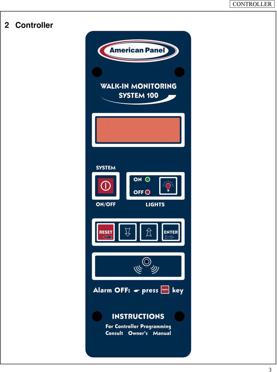
5 CONTROLLER 2 Controller 3
6 PROGRAMMING 3 Parameter Programming All American Panel Corporation walk-in monitoring systems are programmed at the factory. The settings in this manual are considered default for WIMS 100 and were established to suit generic walk-in operating environments. However, the customer may change any of these settings as required. Note: During the programming steps, any delay longer than one minute before pushing the next button will cause the controller to revert to the OFF state. To avoid this, the following instructions should be carefully reviewed and the desired settings should be determined before proceeding. If the controller goes to the OFF state, the programming mode will have to be restarted. Note: During programming, pressing and holding the UP or DOWN button will increase the programming speed. The instructions below contain screens with the exact messages displayed by the controller during the programming procedure. Follow the notes located to the left of these screens. Before entering the programming mode, the controller has to be in the OFF state. If it is not, press and hold for five seconds. To enter the programming mode, press and hold for five seconds. Enter The Access Code To enter the default access code, press the following buttons in order:. When finished, press. Note: If the code entered is not correct, the controller will display the error message and switch back to the previous screen. Note: The access code is a safety feature that limits the access to the programming mode and therefore will prevent unauthorized personnel from tampering with the settings. After entering the code successfully, the controller will ask you if you want to change the code. To leave it unchanged, press. 4

7 PROGRAMMING Press. Door Frame Heater Settings This function will turn the door frame heater on or off. By default, the door frame heater is set to on ( 1 ). If you wish to turn the door frame heater off, change the flashing value from 1 to 0 (off) by pressing or. Press when done. Note: If you set the flashing value to 0, door frame heater off, the controller will skip to alarm settings. In case the flashing value is set to 1, door frame heater on, the controller will guide you thru door frame heater settings This function will display the walk-in temperature which will determine when the door frame heater will start. Set the air temperature inside the walk-in at which the door frame heater will start. To do so press to increase or to decrease the flashing value representing the air temperature. Press when done. (Default value for coolers) This function will set the door frame heater temperature. (Default value for freezers) Press or to change the door frame heater temperature (the flashing value). Once the door frame heater temperature reaches this setting, it will stay close to the set point according to the factory set differential. Note: Set the door frame heater temperature between 75 0 F and F. 5

8 PROGRAMMING Press when done. (Default value for coolers) (Default value for freezers) Press or to set the percentage (flashing value) of the 4 minute cycle which the door frame heater will stay on. The remaining time left of the 4 minute cycle the door frame heater will be off. This cycle will repeat for as long as the controller is on. See the examples below. Ex1: If the flashing value is set 75P (75%), the door frame heater will run for 3 minutes and it will be off for 1 minute. This cycle will repeat for as long as the controller is on. Ex2: If the flashing value is set to 100P (100%), the door frame heater will run continuously. Ex3: If the flashing value is set to 0P (0%), the door frame heater will not run at all. Ex4: If the flashing value is set to 50P (50%), the door frame heater will run for 2 minutes and it will be off for 2 minutes. The cycle will repeat for as long as the controller will be on. Note: Do not set Door Frame Heater Percent to 0P (0%) unless you want to turn the door frame heater off. Press when done. Alarm Settings - High Air Alarm (Default value for coolers) (Default value for freezers) Press or to change the flashing value representing degrees Fahrenheit. If the air temperature goes above this set point, the alarm will go off. 6
, the door frame heater will run continuously. Ex3: If the flashing value is set to 0P (0%), the door frame heater will not run at all.")
9 PROGRAMMING Press when done. Alarm Settings - Low Air Alarm (Default value for coolers) (Default value for freezers) Press or to change the flashing value representing degrees Fahrenheit. If the air temperature goes below this set point, the alarm will go off. You can set low air alarm anywhere between F and 50 0 F. Press when done. Alarm Settings - Time Delay Press or to change the flashing value representing minutes. If the air temperature goes out of the preset limits the alarm will go off only after the time set here elapses. The alarm time delay can be set anywhere between 0 (no delay) and 60 minutes. Press when done Light Off Delay Next the controller will prompt you to set the automatic light off delay. The automatic light off delay is the elapsed time between the moment the user turns the light on and the moment the controller will automatically turn it off. Set the automatic light off delay by pressing or to change the flashing value representing minutes. The automatic light off delay can be set between 1 and 60 minutes. In case the customer does not want an automatic light off delay, set this function to. Press when done. 7
 and 60 minutes. Press when done Light Off Delay Next the controller will prompt you to set the automatic light off delay.")
10 PROGRAMMING 4 Air Temperature Probe Offset As standard, the air temperature probe is located on the door frame, inside the walk-in. The WIMS 100 will display the air temperature at that particular location ONLY. However, WIMS 100 can be adjusted to estimate the temperature of a remote location inside the walk-in. 4.1 Calculating the Probe Temperature Offset Establish the location inside the walk-in where you want to monitor the air temperature. Ex: Return Air Temperature (behind the evaporator) Using a calibrated thermometer, measure the air temperature at that particular location. T MEASURED Read the air temperature on the display of WIMS 100. T WIMS 100 The temperature difference between the two temperatures is the temperature offset. T OFFSET Ex: Return Air Temperature (measured behind the evaporator) 37 0 F WIMS 100 Displayed Temperature 40 0 F The Temperature Offset will be: (37 0 F) - (40 0 F) = -3 0 F 4.2 Adjust the Probe Temperature Offset Make sure the controller is in OFF state. If it is not, press and hold for 5 seconds. Press and hold for ten seconds. To enter the default access code, press the following buttons in order:. When finished, press. Press or to change the displayed unit of temperature. When finished, press. Press, to skip. 8
 Using a calibrated thermometer, measure the air temperature at that particular location.")
11 PROGRAMMING Press, to skip. Adjust the Air Probe Temperature Offset Press or to match the flashing value with the temperature offset (T OFFSET ) calculated in the previous chapter (4.1). The temperature reading at the temperature probe will automatically be changed by the temperature offset entered. When finished, press. Press, to skip. Press, to skip. You have finished adjusting the probe temperature offset. Press will reflect the air temperature at the desired location. to turn the controller on. The display Note: The air probe temperature offset is not to be used to make up for undersized or defective refrigeration systems. If a different temperature is desired inside the walk-in, contact a refrigeration technician to adjust your refrigeration system. Special care should be taken when adjusting the air probe temperature offset. You should never adjust the air probe temperature offset for more than 5 0 F. American Panel Corporation is not responsible for any losses such as food spoilage resulted from misusing the air probe temperature offset. 9

12 PROGRAMMING 5 Change the Access Code To change the Access Code, you have to enter the programming mode. Follow the instructions below. Before entering the programming mode, the controller has to be in the OFF state. If it is not, press and hold for 5 seconds. To enter the programming mode, press and hold for five seconds. Enter The Access Code To enter the default access code, press the following buttons in order:. When finished, press. After entering the code successfully, the controller will ask if you want to change the access code. To change the code, change the flashing value to 1 by pressing or and then press. Enter The New Code Enter any three key combination of the following buttons:. Next, the controller will display for a second the message shown in the figure below and then switch to the three dashes display. 10

13 PROGRAMMING Re-enter the new code. After successfully re-entering the new code, the controller will briefly display the message shown in the figure below. If you wish to skip parameter programming press until you get to the OFF message. To change the controller parameters, see the Parameter Programming section of this manual. Make a note of the new code. 6 Restore the Default Settings 9. To restore the default settings, press and hold and for ten seconds Press. 12. Note: After restoring the default settings, you may have to reprogram the controller. Pay special attention to the door frame heater settings. 11

14 OPERATING 7 Operating WIMS Turn On the Controller From the OFF state, turn the controller on by pressing. The controller needs to stay on in order to operate. Leave it on at all times. 7.2 Read the Walk-in Air Temperature When on, the LED display will indicate the inside air temperature of the walk-in at all times. 7.3 Read the Door Frame Heater Temperature WIMS 100 monitors and controls the door frame heater temperature at all times. To display the door frame heater temperature, press and hold heater temperature. As an example see the illustration on the right.. The display will indicate the door frame When is released, the controller will switch back to air temperature display. 7.4 Operate the Light Switch To turn the light on, press. The green LED, next to the light button, will illuminate indicating ON status of the light. To turn the light off, press one more time. The green LED will go off and the red LED will illuminate indicating OFF status of the light. If the automatic light off feature is enabled, the light will turn off automatically after the preset time expires. If a back-to-back light control option was purchased, the light can be switched on and off from the provided button. 7.5 High Alarm If the air inside the walk-in goes above the preset high limit, the alarm will go off. The buzzer will go off and the display will flash the following message: 12

15 OPERATING 7.6 Low Alarm If the air inside the walk-in goes below the preset low limit, the alarm will go off. Just as in high alarm event, the buzzer will go off and the display will flash the following message: In both cases, Low Alarm and High Alarm, the integrated alarm buzzer and the optional external alarm can be turned off by pressing. However, the visual alarm message will stay on the display until the air temperature enters the preset range. 8 Error Messages Problems beyond the routine maintenance would most likely involve the refrigeration system or the control system. Please contact the factory for assistance if this should occur. Note that the warranty would be voided if these components are serviced by other than trained technicians approved by the manufacturer. There are two error messages that could occur on WIMS 100 display: Air probe is not good Heater probe is not good If any of the error messages occur call a technician to check the integrity of the probes. Here is a chart with acceptable electrical resistance (Ohm) at various temperatures for the temperature probes. o C o F kohm

16 FIELD WIRING 9 Field Wiring Note: All field wiring must be done by a licensed electrician in compliance with the national and local electrical codes. Note: Electrician must provide seal-offs at every conduit entry on warmer side of panels. Seal inside and around all conduits where passing through panels. Make all the connections inside the j-box located on the door frame inside the walk-in, next to the vapor proof light fixture. If an electrical stub-out construction was requested, all the connection wires will be stubbed-out thru the ceiling. In this case, the field connections will be made in a j-box provided by the installer. 9.1 Light Connection Additional Light and 3 Way, 4 Way Light Operation Note: Check the blue print to find out which doors interconnect, if any. Consult the electrical schematics , , or at page 19 for any special lighting configuration (3 way, 4 way application). For additional light connection, consult electrical schematic , at page External Alarm Connection (Optional) As a standard configuration, system 100 is equipped with an external alarm output (120V for up to 150W) for a third party audible/visual alarm. Make the external alarm connections inside the main j-box at terminal blocks labeled 8 and 9; see electrical schematic at page 15. Note: If the system is equipped with the optional dry contact, terminal blocks 8 and 9 will be replaced by a relay to provide the dry contact option. 9.3 Dry Contact Connection - For Temperature Alarm Remote Notification (Optional) The dry contact relay (labeled AL) is located in the main j-box (above the door on the interior of the cabinet). Connect to the relay terminals 14 and 11 for the normally open dry contact; see electrical schematic at page 17. If an electrical stub-out construction was requested, two brown wires from the relay terminals 14 and 11 will be stubbed-out thru the ceiling. 9.4 Dry Contact Connection For Power Failure Remote Notification (Optional) The dry contact relay (labeled W) is located in the main j-box (above the door on the interior of the cabinet). Connect to the relay terminals NO/NC (see el. schematic at page 17), according to the requirements of the notification device (phone dialer). If an electrical stub-out construction was requested, two purple wires from the relay terminals 12 and 11 will be stubbed-out thru the ceiling. In the event of power loss, the dry contact will close. If an open action is needed (if power loss), check the electrical schematic on the relay, the wire at the relay terminal 12 could be moved to relay terminal

17 ELECTRICAL DIAGRAMS 10 Electrical Diagrams 10.1 Standard Door 15

18

19 ELECTRICAL DIAGRAMS 10.2 Dry Contacts 17

20

21 ELECTRICAL DIAGRAMS Way 4 Way Light Control 19
22
23 ELECTRICAL DIAGRAMS 21
24
25 ELECTRICAL DIAGRAMS 23
26 American Panel Corporation 5800 S.E. 78th Street, Ocala, Florida Phone: (352) Fax: (352)
Walk-in Monitoring System 200
 REV. 1/18/16 Cooler is Better! TM Walk-in Monitoring System 200 Used in UL Listed Door Panel Assemblies American Panel Corporation 5800 S.E. 78th Street, Ocala, Florida 34472-3412 Phone: (352) 245-7055
TC-9102 Series Surface Mount Temperature Controllers
 TC-9102 Series Surface Mount Temperature Controllers General Description & Applications The TC-9102 Series Temperature Controller offers a versatile solution for a wide variety of applications that may
Mold Alert... Operation Manual P0270
 Mold Alert... Operation Manual P0270 introduction Congratulations on your purchase of the P0270 Mold Alert! Mold is as old as the Earth and it s everywhere. Under the right set of conditions, it can actually
Gastronorm Supra Cabinet & Counter
 By Appointment to Gastronorm Supra Cabinet & Counter Her Majesty Queen Elizabeth II Suppliers of Commercial Refrigeration Foster Refrigerator (UK) Ltd King s Lynn S e r v i c e M a n u a l Gastronorm Supra
INSTALLATION INSTRUCTIONS
 LIGHTING CONTROL PANELS 4 AND 8 RELAYS INSTALLATION INSTRUCTIONS INSTALLATION OVERVIEW The installation instructions contained in this document are provided as a guide for proper and reliable installation.
AN500T, AN1000, AN1000T, AN1500, AN1500T AN2000, AN2000T
 Product Instruction Manual Accona AN500T, AN1000, AN1000T, AN1500, AN1500T AN2000, AN2000T Panel heater v16.5/5 Version 3.2 Jan 2015 Contents 1. Important safety points 2. Installation 2.1. Wall mounting
SSW-iLM Keypad. Wire Harness Configuration. Note: This product is designed to be installed and serviced by security and lock industry professionals
 SSW-iLM Keypad Note: This product is designed to be installed and serviced by security and lock industry professionals Specifications Case dimensions: 6 1/2 L x 1 3/4 W x 1 1/8 D Electrical: 5-12VDC Only
WAM Remote Wireless Asset Monitoring. Website User Guide
 WAM Remote Wireless Asset Monitoring Website User Guide Table of Contents Overview... 2 Login Page... 2 Quick Start Guide...3-4 Locations Page... 5 Devices Page... 5 Register Devices Page... 6 Temp or
ADDING and/or DELETING PIN NUMBERS (Plus other simple programming commands) in My DK-16 or DK-26 DIGITAL KEYPAD
 in My DK-16 or DK-26 DIGITAL KEYPAD") ADDING and/or DELETING PIN NUMBERS (Plus other simple programming commands) in My DK-16 or DK-26 DIGITAL KEYPAD A recurring call that we get here at Securitron Technical Support is from end users of our
ADDING and/or DELETING PIN NUMBERS (Plus other simple programming commands) in My DK-16 or DK-26 DIGITAL KEYPAD A recurring call that we get here at Securitron Technical Support is from end users of our
GSM Alarm System User Manual
 GSM Alarm System User Manual For a better understanding of this product, please read this user manual thoroughly before using it. Quick Guider After getting this alarm system, you need to do the following
New GSM Alarm System. User s Manual. Profile For a better understanding of this product, please read this user manual thoroughly before using it.
 New GSM Alarm System User s Manual Profile For a better understanding of this product, please read this user manual thoroughly before using it. Chapter 1. Features Chapter 2. Alarm Host Introduction Chapter
PUSH BUTTON START INSTALLATION MANUAL
 PUSH BUTTON START INSTALLATION MANUAL ALTHOUGH THIS PRODUCT HAS BEEN THOROUGHLY TESTED KPIERSON TECHNOLOGIES ASSUMES NO RESPONSIBILITY FOR ANY DAMAGE THAT MAY RESULT BY THE INSTALLATION OF THIS PRODUCT.
Secure Keypads for access control
 torm Secure Keypads for access control Strike Master Read this manual carefully before attempting to install, program or operate the STORM AXS Strike Master Keypad. After installation the Command Summary
NL708 (XWA11V) Walk-In Temp / Door /Alarm / Light Module
 Walk-In Temp / Door /Alarm / Light Module") NL708 (XWA11V) Walk-In Temp / Door /Alarm / Light Module 1. General Description 1 2. General Warnings 1 3. Interface 2 4. Temp Alarms Setting 3 5. Programming 3 6. Light Management 4 7. Installation and
NL708 (XWA11V) Walk-In Temp / Door /Alarm / Light Module 1. General Description 1 2. General Warnings 1 3. Interface 2 4. Temp Alarms Setting 3 5. Programming 3 6. Light Management 4 7. Installation and
Commercial Refrigeration Temperature and Defrost Controls
 Commercial Refrigeration Temperature and Defrost Controls UNI-LINE PRODUCT KNOWLEDGE 2010 Invensys. All Rights Reserved. The names, logos, and taglines identifying the products and services of Invensys
INSTALLATION MANUAL XM3 Reader
 INSTALLATION MANUAL XM3 Reader Conditions Transactions, deliveries et cetera will be according to the general terms of delivery as deposited at the Chamber of Commerce at Meppel, The Netherlands. Registration
Sensi TM. Wi-Fi Programmable Thermostat MANUAL OPERATION. Version: March 2016 2016 Emerson Electric Co. All rights reserved.
 Sensi TM Wi-Fi Programmable Thermostat MANUAL OPERATION Version: March 2016 2016 Emerson Electric Co. All rights reserved. Contents MANUAL OPERATION GUIDE Buttons and Icons 3 Basic Functionality 4 Manual
GENERATOR START CONTROL MODULE - MINI (2 Wire to 3 Wire)
") FEATURES & APPLICATIONS Inexpensive 2 wire to 3 wire start controller for electric start high speed gas generators. Optimized for use with Outback Invertors. Supports three types of 3 wire generator control
FEATURES & APPLICATIONS Inexpensive 2 wire to 3 wire start controller for electric start high speed gas generators. Optimized for use with Outback Invertors. Supports three types of 3 wire generator control
site monitoring Kit Site Monitoring Kit User Manual we prove it.
 site monitoring Kit 1 User Manual Site Monitoring Kit User Manual we prove it. 2 site monitoring Kit Content 1. Introduction 3 2. Content of the Site Monitoring Kit 4 3. Preparation 6 1. Positioning of
SPR-5 FOUR SECTOR COMPOS I TE CONTROL UN I T.
 SPR-5 FOUR SECTOR COMPOS I TE CONTROL UN I T. -SECTORS- EXIT 1 2 3 4 POWER OFF 4 SECTOR SPR-5 The SPR-5 is the culmination of many years experience in control module and power supply design and manufacture,
Comfort Control Relay Panel (CCRP)
") CCRP9 "Commitment to Innovation" OPERATION & INSTALLATION GUIDE FOR Comfort Control Panel (CCRP) Off-Peak System Control 9 Pole CCRP 4 Pole CCRP (Applicable to Software Version 14.0-14.9) "Manufactured
CCRP9 "Commitment to Innovation" OPERATION & INSTALLATION GUIDE FOR Comfort Control Panel (CCRP) Off-Peak System Control 9 Pole CCRP 4 Pole CCRP (Applicable to Software Version 14.0-14.9) "Manufactured
SECTION 26 09 26 LOW VOLTAGE LIGHTING CONTROLS
 SECTION 26 09 26 LOW VOLTAGE LIGHTING CONTROLS PART 1 - GENERAL 1.01 RELATED DOCUMENTS: A. The Conditions of the Contract and applicable requirements of Division 1, "General Requirements", and Section
AC-115 Compact Networked Single Door Controller. Installation and User Manual
 AC-115 Compact Networked Single Controller Installation and User Manual December 2007 Table of Contents Table of Contents 1. Introduction...5 1.1 Key Features... 6 1.2 Technical Specifications... 7 2.
Operating Manual Color Changing Fountains
 Operating Manual Color Changing Fountains 1-877-80-PONDS www.atlanticwatergardens.com Introduction Thank you for purchasing Atlantic s Color Changing Fountains overflowing features that glow from within.
SECTION 11 78 13 MORTUARY REFRIGERATORS
 PART 1 - GENERAL 1.1 DESCRIPTION SECTION 11 78 13 MORTUARY REFRIGERATORS SPEC WRITER NOTE: Delete between //---// if not applicable to project. Also delete any other item or paragraph not applicable in
KCIEN KCIENSBP. Heavy Duty Stainless Steel Illuminated Keypads INSTALLATION MANUAL. Range: DIGICODE (Stand-Alone Keypad)
") KCIENSBP KCIEN Heavy Duty Stainless Steel Illuminated Keypads Range: DIGICODE (Stand-Alone Keypad) INSTALLATION MANUAL Features: Input voltage: 12V to 24V AC or 12V to 48V DC Illuminated keys Heavy duty
KCIENSBP KCIEN Heavy Duty Stainless Steel Illuminated Keypads Range: DIGICODE (Stand-Alone Keypad) INSTALLATION MANUAL Features: Input voltage: 12V to 24V AC or 12V to 48V DC Illuminated keys Heavy duty
Operating Manual for the Electronic Built-in Interval Timer. Micro II (Countdown Timer)
") Operating Manual for the Electronic Built-in Interval Timer Micro II (Countdown Timer) Note: This document has been designed for our OEM customers. They can use it as supporting material when creating
Operating Manual for the Electronic Built-in Interval Timer Micro II (Countdown Timer) Note: This document has been designed for our OEM customers. They can use it as supporting material when creating
POINTS POSITION INDICATOR PPI4
 POINTS POSITION INDICATOR PPI4 Advanced PPI with Adjustable Brightness & Simplified Wiring Monitors the brief positive operating voltage across points motors when they are switched Lights a corresponding
Manual. IP Sensor and Watchdog IPSW2210. I P S W 2 2 1 0 M a n u a l P a g e 1. Relay Output. Power input. 12VDC adapter LED Indicators. 2 Dry.
 IP Sensor and Watchdog IPSW2210 Manual Relay Output Power input 12VDC adapter LED Indicators 1 wire 2 Dry Output Green : Power Yellow: Link temperature & humidity contact inputs LED indicator sensor input
Applied Electronics. Commercial Dimming System UPDATE NOTICE
 REV. A Applied Electronics Commercial Dimming System UPDATE NOTICE This notice is to inform the end user of an additional feature added to this DP12/2400 dimming unit. This unit has been outfitted with
LG Air Conditioning Multi F(DX) Fault Codes Sheet. Multi Split Units
 Fault Codes Sheet. Multi Split Units") Multi Split Units If there is a fault on any LG Multi unit, an Error mark is indicated on the display window of the indoor unit, wired-remote controller, and LED s of outdoor unit control board. A two
Multi Split Units If there is a fault on any LG Multi unit, an Error mark is indicated on the display window of the indoor unit, wired-remote controller, and LED s of outdoor unit control board. A two
Advantium 2 Plus Alarm
 ADI 9510-B Advantium 2 Plus Alarm INSTALLATION AND OPERATING INSTRUCTIONS Carefully Read These Instructions Before Operating Carefully Read These Controls Corporation of America 1501 Harpers Road Virginia
ITC-308 Plug and Play Temperature Controller
 ITC-308 Plug and Play Temperature Controller 1. Overview ITC-308 is an easy-to-use, safe and reliable dual relay output temperature controller. It can be used as Over-temperature protection and automatic
VARIO PROX CARD READER INSTALLATION MANUAL
 VARIO PROX CARD READER INSTALLATION MANUAL TABLE OF CONTENTS 1.0 INTRODUCTION...2 1.1 Legend...3 1.2 Terminology...4 2.0 MOUNTING...5 3.0 WIEGAND CONNECTION...6 4.0 AUX BUTTON INPUT...7 5.0 INSTALLER PROGRAMMING...8
PK-01. Standalone door control module. SATEL sp. z o.o. ul. Schuberta 79 80-172 Gdańsk POLAND tel. + 48 58 320 94 00
 Standalone door control module PK-01 Firmware version 1.00 pk-01_en 06/12 SATEL sp. z o.o. ul. Schuberta 79 80-172 Gdańsk POLAND tel. + 48 58 320 94 00 info@satel.pl www.satel.eu WARNINGS Read carefully
LCD5500Z / PKP-LCD v3.x Installation Instructions
 LCD5500Z / PKP-LCD v3.x Installation Instructions TM Introduction The LCD5500Z / PKP-LCD keypad displays system status using an LCD screen. The keypad can be used on PowerSeries security systems with up
Sigma Control PC INSIDE. 97 psi 187 F R on load
 Sigma Control PC INSIDE 97 psi 187 F R on load Innovation Sigma Control with a PC inside At Kaeser, we pride ourselves on being the world s leading innovator in air system technology. Over twenty-five
Installation and Operating Manual
 Installation and Operating Manual XL-660 Digital Access Control Station Your Partner in Access Control summitaccesscontrol.com Contents Two-Year Limited Warranty 3 PARTS CHECKLIST 4 INTRODUCTION 5 INSTALLATION
Rock-Ola Music Center Set-Up and Installation Guide For all Q-Series models 230V, Export
 Part No. 61745-01 Rock-Ola Music Center Set-Up and Installation Guide For all Q-Series models 230V, Export IMPORTANT SAFETY INSTRUCTIONS a. Read these instructions. b. Keep these instructions. c. Follow
ELECTRONIC THERMOSTAT AND THERMOMETER With SPEED CONTROL
 148 OLD CONCORD TURNPIKE, BARRINGTON NH 03825 USA TEL (603) 868-5720 FAX (603) 868-1040 1-800-435-6708 E-Mail:sales@seafrost.com www.seafrost.com ELECTRONIC THERMOSTAT AND THERMOMETER With SPEED CONTROL
FIRE ALARM AND DETECTION SYSTEMS SECTION 16721
 PART 1 - GENERAL 1.01 WORK INCLUDED FIRE ALARM AND DETECTION SYSTEMS SECTION 16721 A. Provide a complete fully addressable, power limited, fire detection and evacuation system. The system shall be connected
SERVICE MANUAL FOR 12 VDC WALL THERMOSTAT AIR CONDITIONING SYSTEMS ROOF TOP UNITS ONLY
 RV Products Division SERVICE MANUAL FOR 12 VDC WALL THERMOSTAT AIR CONDITIONING SYSTEMS ROOF TOP UNITS ONLY Airxcel, Inc. RV Products Division P.O. Box 4020 Wichita, KS 67204 1976A376 (1-11) TABLE OF CONTENTS
GSM Autodialer Professional GJD700 Speech & Text Autodialer
 Text Edit message GSM Autodialer Professional GJD700 Speech & Text Autodialer Introduction The GSM Autodialer Professional works in conjunction with standard alarm systems and makes use of your preferred
The Child Reminder System Installation Manual
 The Child Reminder System Installation Manual Revised June, 2006 Detailed installation information can be found at www.childreminder.com. Get through your installation quickly and easily by calling 1-888-330-6786
VEHICLE SECURITY SYSTEM G25/G20
 VEHICLE SECURITY SYSTEM G25/G20 Limited Lifetime Warranty This vehicle security system is warranted to the original purchaser, to be free from defects in material and workmanship. The manufacturer will
BLOCK OCCUPANCY DETECTOR WITH SEMAPHORE OPERATION BOD1/DAP4-BR
 BLOCK OCCUPANCY DETECTOR WITH SEMAPHORE OPERATION BOD1/DAP4-BR This Block Occupancy Detector recognises the current drawn by moving trains within a block, and can operate a number of built-in programs
PRODUCTIVITY THROUGH INNOVATION 600 CONTROL DIRECT DRIVE TECHNICAL/OPERATION MANUAL
 Rev. D PRODUCTIVITY THROUGH INNOVATION 600 CONTROL DIRECT DRIVE TECHNICAL/OPERATION MANUAL 10 BORIGHT AVENUE, KENILWORTH NEW JERSEY 07033 TELEPHONE: 800-524-0273 FAX: 908-686-9317 TABLE OF CONTENTS Page
EBDSPIR-PRM, EBDSPIR-PRM-IP
 Product Guide EBDSPIR-PRM, EBDSPIR-PRM-IP Ceiling PIR presence/absence detector Overview The EBDSPIR-PRM PIR (passive infrared) presence detector provides automatic control of lighting loads with optional
User Manual. Humidity-Temperature Chart Recorder. Model RH520
 User Manual Humidity-Temperature Chart Recorder Model RH520 Introduction Congratulations on your purchase of the Extech RH520 Temperature + Humidity Chart Recorder. The RH520 measures and displays Temperature,
Model SRMD Setra Remote Monitoring Display
 Model SRMD Setra Remote Monitoring Display 1.0 GENERAL INFORMATION Thank you for purchasing the Setra Remote Monitoring Display (SRMD). The SRMD is a digital panel meter with a bright 1 LED display for
WAMLocal. Wireless Asset Monitoring - Local Food Safety Software. Software Installation and User Guide BA/WAM-L-F
 Wireless Asset Monitoring - Local Food Safety Software BA/WAM-L-F Software Installation and User Guide System Overview The BAPI Wireless Asset Monitoring Local (WAM Local) Software receives temperature
The Parts of the System
 2 The Parts of the System THE RECEIVER THE RECEIVER FRONT PANEL Power Light This green light on the receiver front panel lights up when the receiver is turned ON. This light flashes when the receiver memory
DC REFRIGERATORS 12/24 VOLTS INSTALLATION AND OWNER S MANUAL
 DC REFRIGERATORS 12/24 VOLTS INSTALLATION AND OWNER S MANUAL Service Information If service or parts are required, contact the nearest Norcold Service Center. To find an authorized Norcold Service Center
75LC multi-monitor Installation and Operating Instructions
 75LC multi-monitor Installation and Operating Instructions MODULARM CORPORATION, 61 MALL DRIVE, COMMACK, NY 11725 www.modularm.com, PH: 631.864.3860, FX: 631.864.3863 Copyright 2009 rev110,11/09 Thank
NO ONE DARES COME CLOSE
 The company behind Viper Auto Security Systems is Directed. Since its inception, Directed has had one purpose, to provide consumers with the finest vehicle security and accessories available. The recipient
Single Station Remote Alarm
 ADI 5106G Certified ISO 9001:2000 Single Station Remote Alarm 529 5106-01-120 529 5106-01-220 INSTALLATION AND OPERATING INSTRUCTIONS Carefully Read These Instructions Before Operating Controls Corporation
LDG SLS-2 Two-Port RJ45 Switch
 SLS-2 OPERATIONS MANUAL MANUAL REV. A LDG SLS-2 Two-Port RJ45 Switch LDG Electronics 1445 Parran Road St. Leonard MD 20685-2903 USA Phone: 410-586-2177 Fax: 410-586-8475 ldg@ldgelectronics.com www.ldgelectronics.com
FAN-PWM-V3. Instructions
 FAN-PWM-V3 Instructions HOLDER AMP BOOKLET YELLOW RING CONNECTORS (2) INSTRUCTION INSTRUCTION BOOKLETBOOKLET ITEMS INCLUDED IN KIT INSTRUCTION ITEMS INCLUDED IN KIT ITEMS INCLUDED IN KIT INSTRUCTION BOOKLET
INSTALLATION/PROGRAMMING INSTRUCTIONS 928 ENTRYCHECK
 3580 Willow Lane, Westlake Village, CA 91361-4921 (805) 494-0622 Fax: (805) 494-8861 www.sdcsecurity.com E-mail: service@sdcsecurity.com INSTALLATION/PROGRAMMING INSTRUCTIONS 928 ENTRYCHECK INTRODUCTION
Table of Contents Function Keys of Your RF Remote Control Quick Setup Guide Advanced Features Setup Troubleshooting
 Congratulations on your purchase of the AT&T U-verse TV Point Anywhere RF Remote Control. This product has been designed to provide many unique and convenient features to enhance your AT&T U-verse experience.
HOBO U14 Data Logger User Manual
 HOBO U14 Data Logger User Manual The U family of data loggers offers reliability and convenient monitoring for applications that require higher accuracy, better resolution, more memory, or USB connectivity
Stop Alert Flasher with G-Force sensor
 Stop Alert Flasher with G-Force sensor Stop Alert module creates brake light flashing effect to catch attention of the drivers behind to avoid dangerous rear end collision. The flasher module is a state
CONTENTS QUICK SETUP & INSTALLATION USER MANUAL. SUPA8 Quick Setup & User Manual
 SUPA8 Quick Setup & User Manual QUICK SETUP & INSTALLATION CONTENTS FACTORY DEFAULTS... 1 INSTALLATION OF THE SECURITY SYSTEM... 2 COMMISSIONING THE DIALLER PANEL... 5 ZONE INPUT CONNECTIONS... 7 PANEL
Installation and Operation Back-UPS 1250, 1300, 1500
 Installation and Operation Back-UPS 1250, 1300, 1500 Inventory bu001a Safety and General Information This unit is intended for indoor use only. Do not operate this unit in direct sunlight, in contact with
FIRE ALARM SYSTEM. A. Shop drawings shall be submitted as follows: 1. Manufacturer's published literature. for aspproval.
 Polk School District Specifications for the New Fire Alarm in the Existing Building Eastside Elementary School FIRE ALARM SYSTEM 1.01 SUBMITTALS A. Shop drawings shall be submitted as follows: 1. Manufacturer's
Owner s Guide Guide du propriétaire Guía para el usuario TH115-AF-GB-10. Programmable thermostat Thermostat programmable Termostato programable
 Owner s Guide Guide du propriétaire Guía para el usuario TH115-AF-GB-10 Programmable thermostat Thermostat programmable Termostato programable Read and save these instructions. Veuillez lire le mode d
Single Zone LCD Thermostat Operating Instructions
 Fan Cool Furnace *Heat Pump or Heat Strip On/Off F Single Zone LCD Thermostat Operating Instructions MODEL 3313192.XXX Cool/Furnace 3313193.XXX Cool/Furnace/Heat Pump 3313194.XXX Cool/Furnace/Heat Strip
Troubleshooting Guide, Freedom and Fleet Power Inverter/Chargers
 Technical Note Freedom/Fleet Power 512-0084-01-01 Rev 1 Troubleshooting Guide, Freedom and Fleet Power Inverter/Chargers Overview This document is a guide for troubleshooting inverters, battery chargers,
Important Operating Instructions and Warranty Information On Your New Electronic AMSEC Safe
 Important Operating Instructions and Warranty Information On Your New Electronic AMSEC Safe MODELS: ES712, ES914, ES149, ES1814, ES813, ES916, ES1014, ES2014, ES412, WES149, WES2114 Read Contents Carefully
ETC TWO STAGE ELECTRONIC TEMPERATURE CONTROL
 RANCO INSTALLATION INSTRUCTIONS ETC TWO STAGE ELECTRONIC TEMPERATURE CONTROL Relay Electrical Ratings PRODUCT DESCRIPTION The Ranco ETC is a microprocessor-based family of electronic temperature controls,
PRO PLM Installation Instructions
 PRO PLM Installation Instructions PROFESSIONAL INSTALLATION STRONGLY RECOMMENDED Installation Precautions: Roll down window to avoid locking keys in vehicle during installation Avoid mounting components
G-100/200 Operation & Installation
 G-100/200 Operation & Installation 2 Contents 7 Installation 15 Getting Started 16 GPS Mode Setup 18 Wheel Sensor Mode Setup 20 Fuel Calibration 23 Basic Operation 24 Telemetery Screen 27 Entering a Distance
www.sebury.com.cn Digital Keypad Use s Manual
 K3 K4 www.sebury.com.cn Digital Keypad Use s Manual Contents Introduction Introduction Specifications Intramural Interface Circuit 3 Mounting 3 Wiring 5 Power UP 7 Engineer Programming Mode 7 The K3/K4
USER MANUAL OPERATION AND USE OF CAR WITH. Diego G3 / NEVO SEQUENTIAL GAS INJECTION SYSTEM
 USER MANUAL OPERATION AND USE OF CAR WITH Diego G3 / NEVO SEQUENTIAL GAS INJECTION SYSTEM Page 2 z 7 Table of contents 1. STARTING THE ENGINE... 3 2. CONTROL PANEL... 3 2.1 Indication of the current level
Intelligent GSM Auto-dial Alarm System User s Manual
 Intelligent GSM Auto-dial Alarm System User s Manual Profile For a better understanding of this product, please read this user manual thoroughly before using it. [Function Instruction] [Control Panel Introduction]
NELSON VOLTAGE MONITOR INSTALLATION & PROGRAMMING MANUAL
 NELSON VOLTAGE MONITOR INSTALLATION & PROGRAMMING MANUAL CONTENTS GENERAL INFORMATION...3 INSTALLATION...3 FIELD WIRING...4 PROGRAMMING...4 Circuit Monitor Options...5 Power Frequency...5 Alarm Silence
Dual Laser InfraRed (IR) Thermometer with Color Alert
 Thermometer with Color Alert") User Manual Dual Laser InfraRed (IR) Thermometer with Color Alert MODEL 42509 Introduction Congratulations on your purchase of the Model 42509 IR Thermometer with Color Alert. This Infrared thermometer
User Manual Dual Laser InfraRed (IR) Thermometer with Color Alert MODEL 42509 Introduction Congratulations on your purchase of the Model 42509 IR Thermometer with Color Alert. This Infrared thermometer
MR8 Loop System OWNER'S MANUAL
 MR8 Loop System OWNER'S MANUAL Contents Introduction... 3 Warranty... 4 Precautions... 5 Front panel... 6 Rear panel... 7 Block diagram... 9 Loop configurations. 10 Control functions. 12 Midi Control Assignments...
OPL BASIC. Dosing System for Professional Laundry machines. Contents
 OPL BASIC Dosing System for Professional Laundry machines Contents 1 Getting Started. Page 2 2 Installation. Page 4 3 Set Up & Operation. Page 8 4 Maintenance & Accessories. Page 10 5 Troubleshooting Page
INSTALLATION GUIDE. www.security.soundstream.com FCC ID NOTICE
 AL.1 AUTO SECURITY SYSTEM INSTALLATION GUIDE www.security.soundstream.com FCC ID NOTICE This device complies with Part 15 of the FCC rules. Operation is subject to the following conditions: 1. This device
SAFETY PRECAUTIONS Read all of the instructions before using this appliance. When using this appliance, always exercise basic safely precautions,
 SAFETY PRECAUTIONS Read all of the instructions before using this appliance. When using this appliance, always exercise basic safely precautions, including the following: Do not use if the power supply
TSn SERIES Surge Protective Device
 Page: 1 of 8 TSn SERIES Surge Protective Installation & Operation Manual 3621 Saunders Avenue www.systems.us Ph 804.355.1100 Richmond, VA 23227 4354 Sales@Systems.us Fax 804.355.8900 Page: 2 of 8 Quick
AUTOMATIC TRANSFER SWITCH CONTROL UNIT OPERATOR S MANUAL
 ATS-220 AUTOMATIC TRANSFER SWITCH CONTROL UNIT OPERATOR S MANUAL For Use in 208 to 240 Volts Single and 3 Phase ATS Systems With 110Volt AC or DC Control Motors and selenoids 4501 NW 27 ave Miami FL 33142
e-ask electronic Access Security Keyless-entry
 e-ask electronic Access Security Keyless-entry e-fob Keyless-entry entry System Full-Function Function Installation Manual FCC ID: TV2EFOB1 (UM20 ~ 22793-02) Table of Contents Introduction... 1 e-fob Operation
What you get Welcome to the best generation of security with remote start. Your system contains everything you need.
 Congratulations Congratulations on the purchase of your state-of-the-art security and remote start system. Reading this Owner s Guide prior to using your system will help maximize the use of your system
Thermistor Thermometer MODEL NO. 93210-00
 Thermistor Thermometer MODEL NO. 93210-00 Cole-Parmer Instrument Co. 625 East Bunker Court Vernon Hills, Illinois U.S.A. 60061-1844 (847) 549-7600 (847) 247-2929 (Fax) 800-323-4340 www.coleparmer.com e-mail:
SERVICE MANUAL REFRIGERATION
 SERVICE MANUAL REFRIGERATION ELECTROLUX HOME PRODUCTS S.p.A. Publication no. Spares Operations Italy 599 36 16-90 Corso Lino Zanussi, 30 031117 I - 33080 PORCIA / PN (ITALY) ITZ/SERVICE/AA Fax +39 0434
Security System. User Guide for the LED Command Center
 Security System User Guide for the LED Command Center MY SECURITY COMPANY IS: CALL BEFORE TEST: THIS SECURITY SYSTEM IS CONNECTED TO TELEPHONE NUMBER: THE SECURITY CONTROL PANEL IS CONNECTED TO THE PHONE
Fire Pump Controllers Remote Alarm Panels
 Fire Pump Controllers Remote Alarm Panels Remote Alarm Panels 1.8 Remote Alarm Panels FDAP-M Electric... DFDAP-M Diesel... Product Specifications... 2 6 9 Features 1-1 DFDAP-M / FDAP-M Remote Alarm Panel
IPX AUTOMATIC IP NETWORK LOSS BACKUP A/B SWITCH INSTRUCTION BOOK IB6444-02
 IPX AUTOMATIC IP NETWORK LOSS BACKUP A/B SWITCH INSTRUCTION BOOK IB6444-02 TABLE OF CONTENTS DESCRIPTION 2 MOUNTING INSTRUCTIONS 2 HOW TO CABLE THE IPX 2/3 POWER SUPPLY INSTALLATION 3 OPERATION 3 CARE
Maintenance Manual PC6010. WARNING This manual contains information on limitations regarding product use and function
 WARNING This manual contains information on limitations regarding product use and function and information on the limitations as to liability of the manufacturer. The entire manual should be carefully
Voice Dialer Alarm System Installation Manual DA-712K
 Voice Dialer Alarm System Installation Manual DA-712K FEATURES: 1. stores 4 sets of telephone number and 4-digit secret cords. each telephone number has a 16-digit capacity. 2. Built-in voice I.C. records
Service Guide 12/27/03 TESTING, SERVICE & REPAIR GUIDE (For SH Space Heating Models & RA Water Heating Models)
") TESTING, SERVICE & REPAIR GUIDE (For SH Space Heating Models & RA Water Heating Models) WARNING - HIGH VOLTAGE AC electrical circuits are connected to this heater. Do not attempt any service work on the
TESTING, SERVICE & REPAIR GUIDE (For SH Space Heating Models & RA Water Heating Models) WARNING - HIGH VOLTAGE AC electrical circuits are connected to this heater. Do not attempt any service work on the
High Temperature InfraRed Thermometer with Laser Pointer
 User s Manual High Temperature InfraRed Thermometer with Laser Pointer MODEL 42540A 6 42540 6 Introduction Congratulations on your purchase of the Model 42540A IR Thermometer. The 42540A is capable of
DIVISION 28 ELECTRONIC SAFETY AND SECURITY SECTION 28 13 00 SECURITY AND ACCESS CONTROL SYSTEM
 DIVISION 28 ELECTRONIC SAFETY AND SECURITY PART 1 GENERAL 1.01 DESCRIPTION A. Division 28 Contractor shall extend a complete Matrix Systems Access Control System as shown on the Drawings and as specified
Fitting/Installation Guide - UNIVERSAL
 ATTENTION: This wiring information is being provided free of charge and on an as is basis, without any representation or warranty. It is your responsibility to verify any circuit before interfacing with
EK908FHL - Thermostat for floor heating
 EK908FHL - Thermostat for floor heating EK908FHL is a programmable thermostat designed for floor warming application or helping to limit floor temperature. This thermostat can be used for hot water radiant
SECURITY ALARM CONTROL PANEL QUICK SETUP & USER MANUAL
 SECURITY ALARM CONTROL PANEL QUICK SETUP & USER MANUAL PINKERTON Quick Setup & User Manual QUICK SETUP & INSTALLATION CONTENTS FACTORY DEFAULTS...1 INSTALLATION OF THE SECURITY SYSTEM...2 COMMISSIONING
1955-1956 Chevy Bel-Era
 Classic Instruments 1955-1956 Chevy Bel-Era Installation Manual Revised January 2, 2014 Page 1 Table of Contents Table of Contents 2 Welcome to the Team of Classic Instruments! 3 55-56 Chevy Part Identification
Installation and Operation Manual Back-UPS BX800CI-AS/BX1100CI-AS
 + Installation and Operation Manual Back-UPS BX800CI-AS/BX1100CI-AS Inventory Safety and General Information bu001c This unit is intended for indoor use only. Do not operate this unit in direct sunlight,