Tune and Chromaticity Tracking in the Tevatron. C.Y. Tan 09 May 2006
|
|
|
- Terence Noah Ball
- 7 years ago
- Views:
Transcription
1 Tune and Chromaticity Tracking in the Tevatron C.Y. Tan 09 May 2006

2 Overview What is the Tevatron tune tracker? Selected results from some stores. (There are many stores with TT running). Planned chromaticity tracker.

3 Tune Tracker There are at least two ways to track the tune Tune fitting which is available for 21.4MHz and 1.7 Ghz Schottky. Slow (~1 Hz) Actively exciting the beam and tracking the zero phase response of the beam. This is the PLL method. Fast (100 Khz limited by ethernet bw)

4 Tune Tracker Principle (Thought Experiment) Young Fermi wants to find the peak a pendulum resonance (SHO). He is armed with Sine wave generator to excite the pendulum Phase detector Detect phase of pendulum w.r.t. phase of sine wave

5 How to find the peak from phase

6 What I need A detector 21. 4MHz Schottky at A1 A kicker 1 foot long stripline BPMs converted to kickers at A1 Can I measure a frequency response?

7 Can we measure a frequency response?

8 In Principle

9 The Hardware
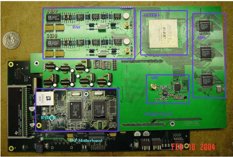
10 Tune Tracker Status Tune Tracker (TT) at Tevatron declared commissioned on 13 Sep 2005 with first successful tracking of both horz and vert tunes in store As of this date, TT has been on for all stores. The data that has been collected was extremely useful for analysis when things went wrong. E.g. Skew quads not ramping, separator polarity did not switch.

11 Normal Store

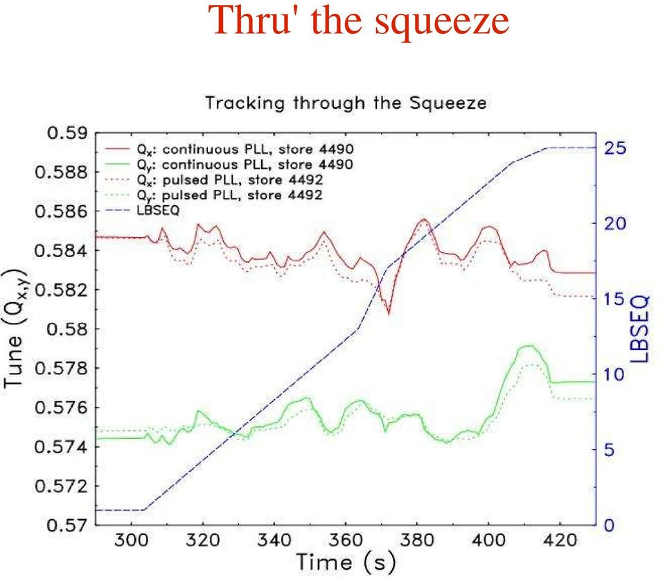
12 Thru' the squeeze
13 When Skew Quads Don't Turn On Flying tunes

14 Tune Tracker Performance TT has performed very well over the past 5-6 months. Very little human intervention. It just works! No retuning required even after 2 unscheduled shutdowns of approximately 1 week each. However, the beam frequency response changed suddenly in the first week of Feb. Cause is still unknown. Also noticed phase drift over a few weeks.

15 Plans No tune feedback plans. RHIC has successfully done feedback but not during stores. Important for LHC! TT will be used as the basis for the chromaticity tracker (CT) using the McGinnis method. LHC evaluating different ways to do chromaticity tracking. SPS experiment planned.
 using")
16 The McGinnis Method Classical method: measures change in RF frequency (i.e. p/p) to betatron frequency change. Q= C f f McGinnis method: Phase modulate the RF frequency. This couples to transverse plane because of chromaticity. Novelty: Phase demodulate the betatron frequency to obtain chromaticity

17 The McGinnis Method (cont'd) The McGinnis formula for calculating chromaticity when using the VSA as a phase demodulator: = 2 Z h k Q 0 mod = chromaticity = slip factor Z = demod. height in radrms mod = size of modulation h = harmonic number k = revolution harmonic Q 0 = fractional betatron tune

18 McGinnis Method (cont'd) McGinnis method requires that: RF be phase modulated. TT supplies the carrier frequency (i.e. Betatron tune) for phase demodulation. Phase demodulated height is related to the chromaticity.

19 Why we need the TT TT will lock at 0. If modulation is outside the bw of the TT, it will not follow the modulation and thus, can be measured w.r.t. the locked frequency.

20 Requirements Modulation frequency must be outside the closed loop bw of the TT. For Tevatron TT, closed loop bw is about 5Hz. Modulation frequency must less than ½ the synchrotron frequency to prevent emittance growth. For Tevatron at 150GeV approx 20Hz. mod is approx. 5 degrees or less to prevent beam loss and tune change < This corresponds to dp/p ~ 1e-5 if chromaticity is 5 to 20 in the Tev.

21 Limitations If only using VSA to demodulate, can only get magnitude of chromaticity. Cannot get sign without adding more hardware. Coming real soon now... Will not work at transition because = 0. Not a problem at Tevatron or LHC. Longitudinal dampers which work on coupled bunch mode zero will damp this. Should not be a problem at the Tevatron because current dampers do not work on mode 0.
22 Set up
23 Demodulated Signal Mod freq = 23Hz mod = 10 deg.
24 Tracking with Phase Modulation ON No beam loss during modulation of mod = 5 deg. Tune moved when chrom knob changed. (Checked that tune change not synch. freq or 23 Hz. However, I need to be sure)
25 Results for Tevatron Note that calibration of phase shifter needs to be checked. McGinnis = 0.83 expected 0.6 if mod =10 o McGinnis = 1.0 expected 1.7 if mod =5 o
26 Using 3D-BBQ TT still at 21.4MHz and locked. (a) phase mod off. (b) phase mod on. mod = 40 deg.
27 BBQ Phase Demodulated mod = 5deg.
28 Chrom Measured using BBQ
29 Planned Implementation (Phase II)
30 Conclusion TT is now routinely used for stores. People are using it in a feedforward sense to tune the Tevatron between stores. Quite robust and not much attention needed for it to work. Future plan is to work on chromaticity tracking. Preliminary work shows that the McGinnis method is promising. However, I need to prove that it will work up the ramp and thru the squeeze. Note that LHC synchrotron frequency is 64 Hz at injection (450GeV) and 23Hz at flattop (7TeV). TT for CT must have closed loop bw of ~5Hz if McGinnis method is used.
31 Acknowledgements The Tevatron group for supporting this project. US-LARP Operated by Universities Research Association Inc. under Contract No. DE-AC02-76CH03000 with the United States Department of Energy.
LHC optics measurement & correction procedures. M. Aiba, R. Calaga, A. Morita, R. Tomás & G. Vanbavinckhove
 LHC optics measurement & correction procedures M. Aiba, R. Calaga, A. Morita, R. Tomás & G. Vanbavinckhove Thanks to: I. Agapov, M. Bai, A. Franchi, M. Giovannozzi, V. Kain, G. Kruk, J. Netzel, S. Redaelli,
Advanced Photon Source. RF Beam Position Monitor Upgrade Robert M. Lill
 Advanced Photon Source RF Beam Position Monitor Upgrade Robert M. Lill Filter Comparator (original design) to ATT LPF A+B ATT BPF S bo ATT ATT LPF 180 A-B 180 ATT BPF D x ti ATT LPF C+D ATT BPF D y 180
MATRIX TECHNICAL NOTES
 200 WOOD AVENUE, MIDDLESEX, NJ 08846 PHONE (732) 469-9510 FAX (732) 469-0418 MATRIX TECHNICAL NOTES MTN-107 TEST SETUP FOR THE MEASUREMENT OF X-MOD, CTB, AND CSO USING A MEAN SQUARE CIRCUIT AS A DETECTOR
Beam Instrumentation Group, CERN ACAS, Australian Collaboration for Accelerator Science 3. School of Physics, University of Melbourne 4
 Prototype tests of a wide-band Synchrotron-Light based Beam Pattern Monitor for measuring charge-couple bunch instabilities in High-Energy Particle Accelerator Beams Sophie Dawson2,3, Mark Boland2,4, David
Advantages of Real-time Spectrum Analyzers in High Energy Physics Applications
 Advantages of Real-time Spectrum Analyzers in High Energy Physics Applications Introduction In High Energy Physics (HEP) applications, the fundamental challenges facing operators and researchers are sustained
FREQUENCY RESPONSE ANALYZERS
 FREQUENCY RESPONSE ANALYZERS Dynamic Response Analyzers Servo analyzers When you need to stabilize feedback loops to measure hardware characteristics to measure system response BAFCO, INC. 717 Mearns Road
Frequency Map Experiments at the Advanced Light Source. David Robin Advanced Light Source
 Frequency Map Experiments at the Advanced Light Source David Robin Advanced Light Source work done in collaboration with Christoph Steier (ALS), Ying Wu (Duke), Weishi Wan (ALS), Winfried Decking (DESY),
10EaZy SW White Paper Choosing the right hardware
 10EaZy SW White Paper Choosing the right hardware Selecting proper hardware for the 10EaZy SW This white paper describes important elements to consider before purchasing hardware intended for sound level
Status of the SOLEIL project Commissioning from Linac to beamlines
 Status of the SOLEIL project Commissioning from Linac to beamlines On behalf of the commissioning team 2 D01-1-CX1/DT/DTC/absorption Y Axis Title 0-200 0 200 400 600 800 1000 1200 1400 X Axis Title 1 Site
Results: Low current (2 10 12 ) Worst case: 800 MHz, 12 50 GeV, 4 turns Energy oscillation amplitude 154 MeV, where
 Worst case: 800 MHz, 12 50 GeV, 4 turns Energy oscillation amplitude 154 MeV, where") Status Focus has shifted to a neutrino factory Two comprehensive designs of acceleration (liancs, arcs) Jefferson Lab, for Fermilab Study CERN (Keil et al.) Jefferson Lab study Low (2 10 12 ) charge per
Status Focus has shifted to a neutrino factory Two comprehensive designs of acceleration (liancs, arcs) Jefferson Lab, for Fermilab Study CERN (Keil et al.) Jefferson Lab study Low (2 10 12 ) charge per
Damping Wigglers in PETRA III
 Damping Wigglers in PETRA III WIGGLE2005, Frascati 21-22.2.2005 Winni Decking, DESY-MPY Introduction Damping Wiggler Parameters Nonlinear Dynamics with DW Operational Aspects Summary DESY and its Accelerators
Engineering Sciences 151. Electromagnetic Communication Laboratory Assignment 3 Fall Term 1998-99
 Engineering Sciences 151 Electromagnetic Communication Laboratory Assignment 3 Fall Term 1998-99 WAVE PROPAGATION II: HIGH FREQUENCY SLOTTED LINE AND REFLECTOMETER MEASUREMENTS OBJECTIVES: To build greater
BIULA AUDIO TRIGGER for Canon Digic II DSLR
 BIULA AUDIO TRIGGER for Canon Digic II DSLR During several years of astroimaging, I ve used every sort of imaging device (from film to SC modified TouCams to modern modified DSLR), but the increasing level
THE BASICS OF PLL FREQUENCY SYNTHESIS
 Supplementary Reading for 27 - Oscillators Ron Bertrand VK2DQ http://www.radioelectronicschool.com THE BASICS OF PLL FREQUENCY SYNTHESIS The phase locked loop (PLL) method of frequency synthesis is now
HIGH-ENERGY COLLIDER PARAMETERS: e + e Colliders (I)
") 28. High-energy collider parameters 1 HIGH-ENERGY COLLIDER PARAMETERS: e + e Colliders (I) Updated in early 2012 with numbers received from representatives of the colliders (contact J. Beringer, LBNL).
28. High-energy collider parameters 1 HIGH-ENERGY COLLIDER PARAMETERS: e + e Colliders (I) Updated in early 2012 with numbers received from representatives of the colliders (contact J. Beringer, LBNL).
VME IF PHASE MODULATOR UNIT. mod. 205-01
 mod. 205-01 02/06 B 1/12 INDEX 1 DESCRIPTION pg. 3 2 FRONT VIEW pg. 4-5 3 TECHNICAL CHARACTERISTICS pg. 6-7 4 OPERATING INSTRUCTIONS pg. 8 5 ANNEX LIST pg. 12 02/06 B 2/12 1 - DESCRIPTION The PHASE MODULATOR
Rotating Machinery Diagnostics & Instrumentation Solutions for Maintenance That Matters www.mbesi.com
 13 Aberdeen Way Elgin, SC 29045 Cell (803) 427-0791 VFD Fundamentals & Troubleshooting 19-Feb-2010 By: Timothy S. Irwin, P.E. Sr. Engineer tsi@mbesi.com Rotating Machinery Diagnostics & Instrumentation
Jeff Thomas Tom Holmes Terri Hightower. Learn RF Spectrum Analysis Basics
 Jeff Thomas Tom Holmes Terri Hightower Learn RF Spectrum Analysis Basics Learning Objectives Name the major measurement strengths of a swept-tuned spectrum analyzer Explain the importance of frequency
SIGNAL GENERATORS and OSCILLOSCOPE CALIBRATION
 1 SIGNAL GENERATORS and OSCILLOSCOPE CALIBRATION By Lannes S. Purnell FLUKE CORPORATION 2 This paper shows how standard signal generators can be used as leveled sine wave sources for calibrating oscilloscopes.
Running in 2011 - Luminosity. Mike Lamont Verena Kain
 Running in 2011 - Luminosity Mike Lamont Verena Kain Presentations Many thanks to all the speakers! Experiments expectations Massi Ferro-Luzzi Pushing the limits: beam Elias Métral Pushing the limits:
RF Network Analyzer Basics
 RF Network Analyzer Basics A tutorial, information and overview about the basics of the RF Network Analyzer. What is a Network Analyzer and how to use them, to include the Scalar Network Analyzer (SNA),
LLRF. Digital RF Stabilization System
 LLRF Digital RF Stabilization System Many instruments. Many people. Working together. Stability means knowing your machine has innovative solutions. For users, stability means a machine achieving its full
Electrical Resonance
 Electrical Resonance (R-L-C series circuit) APPARATUS 1. R-L-C Circuit board 2. Signal generator 3. Oscilloscope Tektronix TDS1002 with two sets of leads (see Introduction to the Oscilloscope ) INTRODUCTION
LHC MACHINE PROTECTION
 LHC MACHINE PROTECTION Rossano Giachino, CERN, Geneva, Switzerland Abstract The energy stored in LHC magnets presents a considerable challenge for commissioning even before any beam is injected. Furthermore,
Synthetic Sensing: Proximity / Distance Sensors
 Synthetic Sensing: Proximity / Distance Sensors MediaRobotics Lab, February 2010 Proximity detection is dependent on the object of interest. One size does not fit all For non-contact distance measurement,
The front end of the receiver performs the frequency translation, channel selection and amplification of the signal.
 Many receivers must be capable of handling a very wide range of signal powers at the input while still producing the correct output. This must be done in the presence of noise and interference which occasionally
Experiment # (4) AM Demodulator
 AM Demodulator") Islamic University of Gaza Faculty of Engineering Electrical Department Experiment # (4) AM Demodulator Communications Engineering I (Lab.) Prepared by: Eng. Omar A. Qarmout Eng. Mohammed K. Abu Foul Experiment
Islamic University of Gaza Faculty of Engineering Electrical Department Experiment # (4) AM Demodulator Communications Engineering I (Lab.) Prepared by: Eng. Omar A. Qarmout Eng. Mohammed K. Abu Foul Experiment
Timing Errors and Jitter
 Timing Errors and Jitter Background Mike Story In a sampled (digital) system, samples have to be accurate in level and time. The digital system uses the two bits of information the signal was this big
Nuclear Magnetic Resonance
 Nuclear Magnetic Resonance Practical Course M I. Physikalisches Institut Universität zu Köln May 15, 2014 Abstract Nuclear magnetic resonance (NMR) techniques are widely used in physics, chemistry, and
Application Note Noise Frequently Asked Questions
 : What is? is a random signal inherent in all physical components. It directly limits the detection and processing of all information. The common form of noise is white Gaussian due to the many random
Brookhaven National Laboratoy, Upton, NY 11973, USA
 10th Beam Instrumentation Workshop BNL, Upton, NY, May 6-9,2002 BNL-69259 BPM System for the SNS Ring and Transfer Lines1 W. C. Dawson, P. Cameron, P. Cerniglia, J. Cupolo, C. Degen, A. DellaPenna, A.
Calorimetry in particle physics experiments
 Calorimetry in particle physics experiments Unit n. 8 Calibration techniques Roberta Arcidiacono Lecture overview Introduction Hardware Calibration Test Beam Calibration In-situ Calibration (EM calorimeters)
Libera at ELETTRA: prehistory, history and present state
 Libera at ELETTRA: prehistory, history and present state S. Cleva, S. Bassanese, R. De Monte, G. Gaio, M. Lonza, C. Scafuri Elettra - Sincrotrone Trieste 1 ELETTRA and FERMI@Elettra plants ELETTRA (SR):
Agilent 8904A Multifunction Synthesizer dc to 600 khz
 Agilent 8904A Multifunction Synthesizer dc to 600 khz Technical Specifications Build complex waveforms from common signals The Agilent Technologies 8904A Multifunction Synthesizer uses VLSIC technology
Using the Equalizer Filter in the VSA Application Firmware for R&S Signal and Spectrum Analyzer Application Note
 Using the Equalizer Filter in the VSA Application Firmware for R&S Signal and Spectrum Analyzer Application Note Products: R&S FSQ R&S FSG R&S FMU R&S FSU R&S FSUP R&S FSMR The R&S spectrum analyzers and
How to Change WaveCall Coverage Areas For WaveCall by Marlink Updated: May 22 nd, 2012
 [HOW TO CHANGE WAVECALL COVERAGE AREAS Satellite Coverage Document] 1 How to Change WaveCall Coverage Areas For WaveCall by Marlink Updated: May 22 nd, 2012 NOTE: To ensure you have the most current information,
A Practical Guide to Free Energy Devices
 A Practical Guide to Free Energy Devices Electrolysis Patents No. 16: Last updated: 30th September 2006 Author: Patrick J. Kelly The major difficulty in using Stan s low-current Water Fuel Cell (recently
Signal Processing in So.ware and Electric Field Sensing
 Signal Processing in So.ware and Electric Field Sensing CSE 466: So.ware for Embedded Systems Winter 2009 B. Mayton University of Washington CSE & Intel Research SeaMle CSE
NUCLEAR MAGNETIC RESONANCE. Advanced Laboratory, Physics 407, University of Wisconsin Madison, Wisconsin 53706
 (revised 4/21/03) NUCLEAR MAGNETIC RESONANCE Advanced Laboratory, Physics 407, University of Wisconsin Madison, Wisconsin 53706 Abstract This experiment studies the Nuclear Magnetic Resonance of protons
Application Note Synchronization and MIMO Capability with USRP Devices Ettus Research
 Application Note Synchronization and MIMO Capability with USRP Devices Ettus Research Introduction Some applications require synchronization across multiple USRP (Universal Software Radio Peripheral) devices.
'Possibilities and Limitations in Software Defined Radio Design.
 'Possibilities and Limitations in Software Defined Radio Design. or Die Eierlegende Wollmilchsau Peter E. Chadwick Chairman, ETSI ERM_TG30, co-ordinated by ETSI ERM_RM Software Defined Radio or the answer
R&S FS-K7 FM Measurement Demodulator for R&S FSx Software Manual
 R&S FS-K7 FM Measurement Demodulator for R&S FSx Software Manual Software Manual Test and Measurement 1141.1821.42 07 The Software Manual R&S FS-K7 describes the following Options: R&S FS-K7 2014 Rohde
MAINTENANCE & ADJUSTMENT
 MAINTENANCE & ADJUSTMENT Circuit Theory The concept of PLL system frequency synthesization is not of recent development, however, it has not been a long age since the digital theory has been couplet with
Fast and Accurate Test of Mobile Phone Boards
 Products: R&S FSP Fast and Accurate Test of Mobile Phone Boards Short test times in conjunction with accurate and repeatable measurement results are essential when testing and calibrating mobile phones
Coupling Impedance of SIS18 and SIS100 beampipe CERN-GSI-Webmeeting
 Coupling Impedance of SIS18 and SIS100 beampipe CERN-GSI-Webmeeting 23 October 2011 TU Darmstadt Fachbereich 18 Institut Theorie Elektromagnetischer Felder Uwe Niedermayer 1 Contents Motivation / Overview
Voltage. Oscillator. Voltage. Oscillator
 fpa 147 Week 6 Synthesis Basics In the early 1960s, inventors & entrepreneurs (Robert Moog, Don Buchla, Harold Bode, etc.) began assembling various modules into a single chassis, coupled with a user interface
INTEGRATED CIRCUITS DATA SHEET. TDA7000 FM radio circuit. Product specification File under Integrated Circuits, IC01
 INTEGRATED CIRCUITS DATA SHEET File under Integrated Circuits, IC01 May 1992 GENERAL DESCRIPTION The is a monolithic integrated circuit for mono FM portable radios, where a minimum on peripheral components
DDX 7000 & 8003. Digital Partial Discharge Detectors FEATURES APPLICATIONS
 DDX 7000 & 8003 Digital Partial Discharge Detectors The HAEFELY HIPOTRONICS DDX Digital Partial Discharge Detector offers the high accuracy and flexibility of digital technology, plus the real-time display
How To Use A Sound Card With A Subsonic Sound Card
 !"## $#!%!"# &"#' ( "#' )*! #+ #,# "##!$ -+./0 1" 1! 2"# # -&1!"#" (2345-&1 #$6.7 -&89$## ' 6! #* #!"#" +" 1##6$ "#+# #-& :1# # $ #$#;1)+#1#+

MYRICOM, INC. TEST REPORT FOR THE SERVER RACK, 10G-PCIE2-8B2-2S & 10G-PCIE2-8B2-2QP FCC PART 15 SUBPART B SECTIONS 15.107 AND 15.109 CLASS A TESTING
 TESTING CERT #803.01, 803.02, 803.05, 803.06 MYRICOM, INC. TEST REPORT FOR THE SERVER RACK, 10G-PCIE2-8B2-2S & 10G-PCIE2-8B2-2QP FCC PART 15 SUBPART B SECTIONS 15.107 AND 15.109 CLASS A TESTING DATE OF
QAM Demodulation. Performance Conclusion. o o o o o. (Nyquist shaping, Clock & Carrier Recovery, AGC, Adaptive Equaliser) o o. Wireless Communications
 o o. Wireless Communications") 0 QAM Demodulation o o o o o Application area What is QAM? What are QAM Demodulation Functions? General block diagram of QAM demodulator Explanation of the main function (Nyquist shaping, Clock & Carrier
0 QAM Demodulation o o o o o Application area What is QAM? What are QAM Demodulation Functions? General block diagram of QAM demodulator Explanation of the main function (Nyquist shaping, Clock & Carrier
Jeff Thomas Tom Holmes Terri Hightower. Learn RF Spectrum Analysis Basics
 Jeff Thomas Tom Holmes Terri Hightower Learn RF Spectrum Analysis Basics Agenda Overview: Spectrum analysis and its measurements Theory of Operation: Spectrum analyzer hardware Frequency Specifications
L and C connected together. To be able: To analyse some basic circuits.
 circuits: Sinusoidal Voltages and urrents Aims: To appreciate: Similarities between oscillation in circuit and mechanical pendulum. Role of energy loss mechanisms in damping. Why we study sinusoidal signals
A Network Analyzer For Active Components
 A Network Analyzer For Active Components EEEfCom 29-30 Juni ULM Marc Vanden Bossche, NMDG Engineering Remi Tuijtelaars, BSW Copyright 2005 NMDG Engineering Version 2 Outline Review of S-parameters Theory
Study of electron cloud at MI and slip stacking process simulation
 Study of electron cloud at MI and slip stacking process simulation Alexandr S. Valkovich Purpose 1.Understand the slip stacking process which happens in the Main Injector. 2. Calculation of bunch distortion
DDX 7000 & 8003. Digital Partial Discharge Detectors FEATURES APPLICATIONS
 DDX 7000 & 8003 Digital Partial Discharge Detectors The HAEFELY HIPOTRONICS DDX Digital Partial Discharge Detector offers the high accuracy and flexibility of digital technology, plus the real-time display
RF SYSTEM FOR VEPP-5 DAMPING RING
 Ó³ Ÿ. 2006.. 3, º 7(136).. 60Ä64 Š 621.384.634.14 RF SYSTEM FOR VEPP-5 DAMPING RING Ye. Gusev, N. Kot, S. Krutikhin, I. Kuptsov, G. Kurkin, I. Makarov, N. Matyash, L. Mironenko, S. Motygin, V. Osipov,
APSYN420A/B Specification 1.24. 0.65-20.0 GHz Low Phase Noise Synthesizer
 APSYN420A/B Specification 1.24 0.65-20.0 GHz Low Phase Noise Synthesizer 1 Introduction The APSYN420 is a wideband low phase-noise synthesizer operating from 0.65 to 20 GHz. The nominal output power is
Making Spectrum Measurements with Rohde & Schwarz Network Analyzers
 Making Spectrum Measurements with Rohde & Schwarz Network Analyzers Application Note Products: R&S ZVA R&S ZVB R&S ZVT R&S ZNB This application note describes how to configure a Rohde & Schwarz Network
Germanium Diode AM Radio
 Germanium Diode AM Radio LAB 3 3.1 Introduction In this laboratory exercise you will build a germanium diode based AM (Medium Wave) radio. Earliest radios used simple diode detector circuits. The diodes
Status of the HOM Damped Cavity for the Willy Wien Ring
 Status of the HOM Damped Cavity for the Willy Wien Ring Ernst Weihreter / BESSY Short Review of HOM Damped Cavity Prototype Modifications for the Willy Wien Ring Cavity Results of Low Power Measurements
How PLL Performances Affect Wireless Systems
 May 2010 Issue: Tutorial Phase Locked Loop Systems Design for Wireless Infrastructure Applications Use of linear models of phase noise analysis in a closed loop to predict the baseline performance of various
Oscillators. 2.0 RF Sine Wave Oscillators. www.learnabout-electronics.org. Module. RF Oscillators
 Module 2 www.learnabout-electronics.org Oscillators 2.0 RF Sine Wave Oscillators What you ll Learn in Module 2 Section 2.0 High Frequency Sine Wave Oscillators. Frequency Control in RF Oscillators. LC
= V peak 2 = 0.707V peak
 BASIC ELECTRONICS - RECTIFICATION AND FILTERING PURPOSE Suppose that you wanted to build a simple DC electronic power supply, which operated off of an AC input (e.g., something you might plug into a standard
CLOCK AND SYNCHRONIZATION IN SYSTEM 6000
 By Christian G. Frandsen Introduction This document will discuss the clock, synchronization and interface design of TC System 6000 and deal with several of the factors that must be considered when using
COUPLING / DECOUPLING NETWORK (CDN) FOR UNSCREENED BALANCED PAIRS
 FOR UNSCREENED BALANCED PAIRS") IEC / EN 61000-4-6 specifies the design and performance of a range of coupling / decoupling networks (CDNs). Each CDN is specific to the type of cable and the intended signal carried on the cable. Teseq
IEC / EN 61000-4-6 specifies the design and performance of a range of coupling / decoupling networks (CDNs). Each CDN is specific to the type of cable and the intended signal carried on the cable. Teseq
Design and development of Configurable BPM readout system for ILSF
 Abstract Design and development of Configurable BPM readout system for ILSF M. Shafiee 1,2, J.Rahighi, M.Jafarzadeh, 1 ILSF, Tehran, Iran A.H.Feghhi, 2 Shahid beheshti University, Tehran, Iran A configurable
AM TRANSMITTERS & RECEIVERS
 Reading 30 Ron Bertrand VK2DQ http://www.radioelectronicschool.com AM TRANSMITTERS & RECEIVERS Revision: our definition of amplitude modulation. Amplitude modulation is when the modulating audio is combined
Agilent AN 1316 Optimizing Spectrum Analyzer Amplitude Accuracy
 Agilent AN 1316 Optimizing Spectrum Analyzer Amplitude Accuracy Application Note RF & Microwave Spectrum Analyzers Table of Contents 3 3 4 4 5 7 8 8 13 13 14 16 16 Introduction Absolute versus relative
Numerical Calculation of Beam Coupling Impedances in the Frequency Domain using the Finite Integration Technique
 Numerical Calculation of Beam Coupling Impedances in the Frequency Domain using the Finite Integration Technique Uwe Niedermayer and Oliver Boine-Frankenheim 24 August 2012 TU Darmstadt Fachbereich 18
7. Beats. sin( + λ) + sin( λ) = 2 cos(λ) sin( )
 + sin( λ) = 2 cos(λ) sin( )") 34 7. Beats 7.1. What beats are. Musicians tune their instruments using beats. Beats occur when two very nearby pitches are sounded simultaneously. We ll make a mathematical study of this effect, using
34 7. Beats 7.1. What beats are. Musicians tune their instruments using beats. Beats occur when two very nearby pitches are sounded simultaneously. We ll make a mathematical study of this effect, using
Tevatron BPM Instrumentation Upgrade Technical Review
 Tevatron BPM Instrumentation Upgrade Technical Review Tuesday, December 16, 2003 Goal: To review the proposed BPM upgrade technology choice and project plan. Review Committee: Marvin Johnson (Chair) Al
Harmonics and Noise in Photovoltaic (PV) Inverter and the Mitigation Strategies
 Inverter and the Mitigation Strategies") Soonwook Hong, Ph. D. Michael Zuercher Martinson Harmonics and Noise in Photovoltaic (PV) Inverter and the Mitigation Strategies 1. Introduction PV inverters use semiconductor devices to transform the
Soonwook Hong, Ph. D. Michael Zuercher Martinson Harmonics and Noise in Photovoltaic (PV) Inverter and the Mitigation Strategies 1. Introduction PV inverters use semiconductor devices to transform the
25. AM radio receiver
 1 25. AM radio receiver The chapter describes the programming of a microcontroller to demodulate a signal from a local radio station. To keep the circuit simple the signal from the local amplitude modulated
Power Amplifier Gain Compression Measurements
 Technical Brief Power Amplifier Gain Compression Measurements GPIB Private Bus Sweep Out Sweep In Pulse In AC Mod Out Blank/Marker Out Blanking In Overview The 1 db gain compression of an amplifier describes
1. The Slotted Line. ECE 584 Microwave Engineering Laboratory Experiments. Introduction:
 ECE 584 Microwave Engineering Laboratory Experiments 1. The Slotted Line Introduction: In this experiment we will use a waveguide slotted line to study the basic behavior of standing waves and to measure
Using Spectrum Analyzers For Signal Monitoring
 Using Spectrum Analyzers For Signal Monitoring Presented by: 3 March 004 1 1 At the completion of this module you will have an understanding of how commercially available spectrum analyzers can be used
13C NMR Spectroscopy
 13 C NMR Spectroscopy Introduction Nuclear magnetic resonance spectroscopy (NMR) is the most powerful tool available for structural determination. A nucleus with an odd number of protons, an odd number
Choosing a Phase Noise Measurement Technique Concepts and Implementation Terry Decker Bob Temple
 Choosing a Phase Noise Measurement Technique Concepts and Implementation Terry Decker Bob Temple RF & Microwave Measurement Symposium and Exhibition Terry Decker, received her BA in Physics from Carleton
Agilent PN 8753-1 RF Component Measurements: Amplifier Measurements Using the Agilent 8753 Network Analyzer. Product Note
 Agilent PN 8753-1 RF Component Measurements: Amplifier Measurements Using the Agilent 8753 Network Analyzer Product Note 2 3 4 4 4 4 6 7 8 8 10 10 11 12 12 12 13 15 15 Introduction Table of contents Introduction
Lecture 3: Signaling and Clock Recovery. CSE 123: Computer Networks Stefan Savage
 Lecture 3: Signaling and Clock Recovery CSE 123: Computer Networks Stefan Savage Last time Protocols and layering Application Presentation Session Transport Network Datalink Physical Application Transport
Op Amp Circuit Collection
 Op Amp Circuit Collection Note: National Semiconductor recommends replacing 2N2920 and 2N3728 matched pairs with LM394 in all application circuits. Section 1 Basic Circuits Inverting Amplifier Difference
Line Reactors and AC Drives
 Line Reactors and AC Drives Rockwell Automation Mequon Wisconsin Quite often, line and load reactors are installed on AC drives without a solid understanding of why or what the positive and negative consequences
BEPC UPGRADES AND TAU-CHARM FACTORY DESIGN
 BEPC UPGRADES AND TAU-CHARM FACTORY DESIGN Abstract BEPC Group, presented by Yingzhi Wu Institute of High Energy Physics, Beijing 100039, P.R. China The luminosity upgrades of the BEPC are briefly reviewed.
0HDVXULQJWKHHOHFWULFDOSHUIRUPDQFH FKDUDFWHULVWLFVRI5),)DQGPLFURZDYHVLJQDO SURFHVVLQJFRPSRQHQWV
,)DQGPLFURZDYHVLJQDO SURFHVVLQJFRPSRQHQWV") 0HDVXULQJWKHHOHFWULFDOSHUIRUPDQFH FKDUDFWHULVWLFVRI5),)DQGPLFURZDYHVLJQDO SURFHVVLQJFRPSRQHQWV The treatment given here is introductory, and will assist the reader who wishes to consult the standard texts
0HDVXULQJWKHHOHFWULFDOSHUIRUPDQFH FKDUDFWHULVWLFVRI5),)DQGPLFURZDYHVLJQDO SURFHVVLQJFRPSRQHQWV The treatment given here is introductory, and will assist the reader who wishes to consult the standard texts
Optical Fibres. Introduction. Safety precautions. For your safety. For the safety of the apparatus
 Please do not remove this manual from from the lab. It is available at www.cm.ph.bham.ac.uk/y2lab Optics Introduction Optical fibres are widely used for transmitting data at high speeds. In this experiment,
Progettare per il Solid State Lighting: le sfide da superare
 Progettare per il Solid State Lighting: le sfide da superare Power supply - Photometry Remote Control Dott. Ing. Stefano Scalzi stefano.scalzi@torand.it www.torand.it Company introduction Target markets
Physics 120 Lab 6: Field Effect Transistors - Ohmic region
 Physics 120 Lab 6: Field Effect Transistors - Ohmic region The FET can be used in two extreme ways. One is as a voltage controlled resistance, in the so called "Ohmic" region, for which V DS < V GS - V
SR2000 FREQUENCY MONITOR
 SR2000 FREQUENCY MONITOR THE FFT SEARCH FUNCTION IN DETAILS FFT Search is a signal search using FFT (Fast Fourier Transform) technology. The FFT search function first appeared with the SR2000 Frequency
Successfully negotiating the PCI EXPRESS 2.0 Super Highway Towards Full Compliance
 Successfully negotiating the PCI EXPRESS 2.0 Super Highway Towards Full Compliance Page 1 Agenda Introduction PCIe 2.0 changes from 1.0a/1.1 Spec 5GT/s Challenges Error Correction Techniques Test tool
ULTRAFAST LASERS: Free electron lasers thrive from synergy with ultrafast laser systems
 Page 1 of 6 ULTRAFAST LASERS: Free electron lasers thrive from synergy with ultrafast laser systems Free electron lasers support unique time-resolved experiments over a wide range of x-ray wavelengths,
Investigations on Critical Higher Order Modes in CEBAF Upgrade Cavities
 Investigations on Critical Higher Order Modes in CEBAF Upgrade Cavities F. Marhauser Thanks also to H. Wang and K. Tian 27. August 2009 How HOMs are excited and why they are important - Wakefields- some
Analysis of Immunity by RF Wireless Communication Signals
 64 PIERS Proceedings, Guangzhou, China, August 25 28, 2014 Analysis of Immunity by RF Wireless Communication Signals Hongsik Keum 1, Jungyu Yang 2, and Heung-Gyoon Ryu 3 1 EletroMagneticwave Technology
DEVELOPMENT OF THE SWISSFEL UNDULATOR BPM SYSTEM
 Proceedings of BC2014, Monterey, CA, USA DEVELOPMENT OF THE SWSSFEL UNDULATOR BPM SYSTEM M. Stadler #, R. Baldinger, R. Ditter, B. Keil, F. Marcellini, G. Marinkovic, M. Roggli, M. Rohrer PS, Villigen,
Section 3. Sensor to ADC Design Example
 Section 3 Sensor to ADC Design Example 3-1 This section describes the design of a sensor to ADC system. The sensor measures temperature, and the measurement is interfaced into an ADC selected by the systems
Modification Details.
 Front end receiver modification for DRM: AKD Target Communications receiver. Model HF3. Summary. The receiver was modified and capable of receiving DRM, but performance was limited by the phase noise from
Reading: HH Sections 4.11 4.13, 4.19 4.20 (pgs. 189-212, 222 224)
") 6 OP AMPS II 6 Op Amps II In the previous lab, you explored several applications of op amps. In this exercise, you will look at some of their limitations. You will also examine the op amp integrator and
6 OP AMPS II 6 Op Amps II In the previous lab, you explored several applications of op amps. In this exercise, you will look at some of their limitations. You will also examine the op amp integrator and
Tamura Closed Loop Hall Effect Current Sensors
 Tamura Closed Loop Hall Effect Current Sensors AC, DC, & Complex Currents Galvanic Isolation Fast Response Wide Frequency Bandwidth Quality & Reliability RoHs Compliance Closed Loop Hall Effect Sensors
Positive Feedback and Oscillators
 Physics 3330 Experiment #6 Fall 1999 Positive Feedback and Oscillators Purpose In this experiment we will study how spontaneous oscillations may be caused by positive feedback. You will construct an active