MasterCella. Foglio istruzioni. Technical leaflet. Notice d instructions. Gebrauchsanleitungen. Hoja de instrucciones.
|
|
|
- Austin Evans
- 8 years ago
- Views:
Transcription
1 MasterCella Foglio istruzioni Technical leaflet Notice d instructions Gebrauchsanleitungen Hoja de instrucciones Folha instruções

2 Contents Technical leafl et 3 EXAMPLES OF TERMINAL BOARDS CONNECTION 14 Smaltimento del prodotto L apparecchiatura (o il prodotto) deve essere oggetto di raccolta separata in conformità alle vigenti normative locali in materia di smaltimento Disposal of the product The appliance (or the product) must be disposed of separately in accordance with the local waste disposal legislation in force Élimination du produit L équipement (ou le produit) doit faire l objet d un ramassage particulier en conformité avec les normes en vigueur locales en matière d élimination des déchets Entsorgung des Produktes Das Gerät (oder Produkt) muss im Mülltrennungsverfahren in Übereinstimmung mit den örtlichen Entsorgungsnormen entsorgt werden. Reciclage del producto Los componentes (o el producto) deben ser tratados separadamente en conformidad a la normativa local vigente en materia de reciclaje Descarte do produto O dispositivo (ou o produto) deve ser disposto separadamente de acordo com a legislação local para resíduos AVVERTENZE IMPORTANTI Il prodotto CAREL è un prodotto avanzato, il cui funzionamento è specifi cato nella documentazione tecnica fornita col prodotto o scaricabile, anche anteriormente all acquisto, dal sito internet Il cliente (costruttore, progettista o installatore dell equipaggiamento fi nale) si assume ogni responsabilità e rischio in relazione alla fase di confi gurazione del prodotto per il raggiungimento dei risultati previsti in relazione all installazione e/o equipaggiamento fi nale specifi co. La mancanza di tale fase di studio, la quale è richiesta/indicata nel manuale d uso, può generare malfunzionamenti nei prodotti fi nali di cui CAREL non potrà essere ritenuta responsabile. Il cliente fi nale deve usare il prodotto solo nelle modalità descritte nella documentazione relativa al prodotto stesso. La responsabilità di CAREL in relazione al proprio prodotto è regolata dalle condizioni generali di contratto CAREL editate nel sito e/o da specifi ci accordi con i clienti. IMPORTANT WARNINGS The CAREL product is a state-of-the-art product, whose operation is specifi ed in the technical documentation supplied with the product or can be downloaded, even prior to purchase, from the website The client (builder, developer or installer of the fi nal equipment) assumes every responsibility and risk relating to the phase of confi guration the product in order to reach the expected results in relation to the specifi c fi nal installation and/or equipment. The lack of such phase of study, which is requested/indicated in the user manual, can cause the fi nal product to malfunction of which CAREL can not be held responsible. The fi nal client must use the product only in the manner described in the documentation related to the product itself. The liability of CAREL in relation to its own product is regulated by CAREL s general contract conditions edited on the website and/or by specifi c agreements with clients. AVERTISSEMENTS IMPORTANTS Le produit CAREL est un produit avancé dont le fonctionnement est spécifi é dans la documentation technique fournie avec le produit ou téléchargeable, même avant l achat, du site Internet Le client (constructeur, concepteur ou installateur de l équipement fi nal) assume toutes les responsabilités et risques quant à la confi guration du produit pour l obtention des résultats prévus quant à l installation et/ou à l équipement fi nal spécifi que. L absence de cette phase d étude qui est requise/indiquée dans le manuel d instructions peut provoquer des dysfonctionnements des produits fi nals dont CAREL ne pourra en aucun cas être jugée responsable. Le client fi nal doit utiliser le produit exclusivement selon les modes décrits dans la documentation correspondant au produit. La responsabilité de CAREL en ce qui concerne son produit est réglée par les conditions générales de contrat CAREL publiées sur le site com et/ou par des accords spécifi ques stipulés avec les clients WICHTIGE HINWEISE Das CAREL Produkt ist ein Produkt nach dem neuesten Stand der Technik, dessen Betriebsanleitungen in den dem Produkt beiliegenden technischen Spezifi kationen enthalten sind oder - auch vor dem Kauf - von der Internetseite heruntergeladen werden können. Der Kunde (Hersteller, Planer oder Installateur der Endausstattung) übernimmt jede Haftung und Risiken in Bezug auf die Produktkonfi guration zur Erzielung der bei der Installation und/oder spezifi schen Endausstattung vorgesehenen Resultate. Die Unterlassung dieser Phase, die im Benutzerhandbuch verlangt/ angegeben ist, kann zu Funktionsstörungen der Endprodukte führen, für welche CAREL nicht verantwortlich gemacht werden kann. Der Endkunde darf das Produkt nur auf die in den Produktspezifi kationen beschriebenen Weisen verwenden. Die Haftung CARELS für die eigenen Produkte ist von den allgemeinen CAREL Vertragsbedingungen (siehe Internetseite und/oder durch spezifi sche Vereinbarungen mit den Kunden geregelt. ADVERTENCIAS IMPORTANTES El producto CAREL es un producto avanzado, cuyo funcionamiento está especifi cado en la documentación técnica suministrada con el producto o descargable, incluso antes de la compra, desde el sitio de internet El cliente (constructor, proyectista o instalador del equipo fi nal) asume toda la responsabilidad y el riesgo relativos a la fase de confi guración del producto con el fi n de los resultados previstos en relación a la instalación y/o equipamiento fi nal específi co. Pasar por alto dicha fase de estudio, la cual es solicitada/indicada en el manual de uso, puede generar funcionamientos anómalos en los productos fi nales, de los cuales no se podrá responsabilizar a CAREL. El cliente fi nal debe utilizar el producto sólo en las modalidades descritas en la documentación relativa al producto en sí. La responsabilidad de CAREL en relación a su producto propio está regulada por las condiciones generales del contrato de CAREL editadas en el sitio com y/o por los acuerdos específi cos con los clientes. ADVERTÊNCIAS IMPORTANTES O produto CAREL é um produto avançado, cujo funcionamento está descrito na documentação técnica fornecida com o produto ou que pode ser descarregada, mesmo antes da aquisição do produto, a partir do site O cliente (fabricante, projectista ou instalador do equipamento fi nal) assume qualquer tipo de responsabilidade e de risco relativos à fase de confi guração do produto para a obtenção dos resultados previstos em relação à instalação e/ou equipamento fi nal específi co. A falta desta fase de estudo, como exigida/indicada no manual de uso, pode gerar mau funcionamentos nos produtos fi nais pelos quais a CAREL não poderá ser julgada responsável. O cliente fi nal deve utilizar o produto somente nas modalidades descritas na documentação relativa ao produto. A responsabilidade da CAREL em relação ao próprio produto é regulada pelas condições gerais de contrato CAREL editadas no site e/ou por específi cos acordos com os clientes.
 muss im Mülltrennungsverfahren in Übereinstimmung mit den örtlichen Entsorgungsnormen entsorgt werden.")
3 1. INTRODUCTION MasterCella is the new electronic controller for static or ventilated refrigerating units, able to manage all the actuators normally featured, such as: compressors, fans, defrost, alarms and lights. The MasterCella case is IP65 and the electrical wiring is especially simple, due to the fact that the front panel can be removed. The MasterCella case allows installation either on the panel or on the wall. ENGLISH 2. OPTION CODES CODE DESCRIPTION IRTRRES000 small infrared remote control IROPZSEM10 RS485 serial board with automatic recognition of the polarity +/- IROPZSEM30 RS485 serial board with automatic recognition of the polarity +/- and connection of repeater display PST00VR100 remote repeater display IR00RG0000 remote repeater display ir33 range green display IR00RR0000 remote repeater display ir33 range red display PSTCON0300 connection cables to the repeater display, one end with screw, 3 metres long PSTCON1000 connection cables to the repeater display, one end with screw, 10 metres long PSOPZKEY00 parameter programming key with 12V batteries included PSOPZKEYA0 parameter programming key with external 230 Vac power supply IROPZKEY00 parameter programming key with extended memory and 12V batteries included IROPZKEYA0 parameter programming key with extended memory and external 230 Vac power supply VPMSTDKY*0(1,2) programming key kit MDOPZCA000 optional board with 3 repeat connectors MDOPZCB000 optional board with 5 repeat connectors CEL Disconnecting switch 32 A CEL Shaft H= 85 mm CEL Yellow/red disconnecting switch Tab.2.a 3. DISPLAY MasterCella is fi tted with a three digit LED display for the temperature, and icons for displaying the operating status. It can also be connected, using a special interface, to a further display, used, for example, to show the reading of the third probe. 3.1 Signals on the display Icon Function Normal Operation Startup ON OFF flashing COMPRESS. compressor on compressor off compressor call FAN fan on fan off fan call DEFROST defrost in progress no defrost call defrost call AUX AUX auxiliary output active AUX auxiliary output not active anti-sweat heater function active ALARM delayed external alarm (before the time A7 has elapsed) no alarm present alarms in norm. operation (e.g. high/low temperature) or alarm from external digital input, immediate or delayed CLOCK if at least one timed defrost has been set no timed defrost set clock alarm ON if Real-Time Clock present LIGHT LIGHT auxiliary output active LIGHT auxiliary output not active anti-sweat heater function active SERVICE no malfunction malfunction (e.g. EEPROM error or probes faulty) HACCP HACCP function enabled HACCP function not enabled HACCP alarm saved (HA and/or HF) CYCLE CONTINUOUS CYCLE function activated CONTINUOUS CYCLE function not activated CONTINUOUS CYCLE function call Tab. 3.a The status indicates that the function has been called but cannot be run until the delay timers expire. 3

4 3.2 Buttons on the keypad Icon Button Normal operation Start-up Automatic address Pressing the button alone Pressing together with other buttons assignment request HACCP enters the menu to display and delete of the HACCP alarms ON/OFF if pressed for more than 5 s, switches the unit on/off PRG/MUTE if pressed for more than 5 s, accesses the menu for setting the type F parameters (Frequent). In the event of alarms: mutes the audible alarm (buzzer) and deactivates the alarm relay UP/CC if pressed for more than 5 s, activates/ deactivates the continuous cycle LUCE if pressed for more than 1 s, activates/ deactivates auxiliary output 2 AUX if pressed for more than 1 s, activates deactivates auxiliary output 1 DOWN/DEF if pressed for more than 5 s, activates/ deactivates a manual defrost SET if pressed for more than 1 s, displays and/or sets the set point if pressed for more than 5s together with the SET button, accesses the menu for setting the type C parameters (Confi guration) or downloading the parameters. if pressed for more than 5s together with the UP/CC button, resets any alarms with manual reset if pressed for more than 5s together with the SET button, starts the report printing procedure (function available but management to be implemented) if pressed for more than 5s together with the PRG/MUTE button, resets any alarms with manual reset if pressed for more than 5s together with the PRG/MUTE button, accesses the menu for setting type C parameters (Confi guration) or downloading the parameters if pressed for more than 5s together with the UP/CC button, starts the report printing procedure (function available but management to be implemented) if pressed for more than 5 s at start-up, activates the procedure for restoring the default parameters if pressed for more than 1 s, starts the automatic serial address assignment procedure Tab. 3.b ENGLISH Setting the set point (desired temperature value) To display or set the set point, proceed as follows: 1) press the set button for more than 1 second to display the set point; 2) increase or decrease the value of the set point with the and buttons respectively, until reaching the desired value; 3) press the set button again to confi rm the new value. Resetting alarms with manual reset All the alarms with manual reset can be reset by pressing the prg and buttons together for more than 5 s. Manual defrost As well as the automatic defrost, a manual defrost can be started if the temperature conditions are right, by pressing the button for 5 seconds. ON/OFF button Pressing the button for 5 seconds switches the unit on/off. When the controller is off it is in standby mode, therefore before performing maintenance on the unit, power must be disconnected. HACCP function MasterCella is compliant with the HACCP standards, as it monitors the temperature of the food stored. Alarm HA = maximum threshold exceeded: in addition, up to three HA events are saved (HA, HA1, HA2), respectively from the most recent (HA) to the oldest (HA2), with a signal HAn that displays the number of HA events that have occurred. Alarm HF = power failure for more than 1 minute and maximum threshold AH exceeded: up to three HF events are saved (HF, HF1, HF2), respectively from the most recent (HF) to the oldest (HF2), with a signal HFn that displays the number of HF events that have occurred. Setting the HA/HF alarm: parameter AH (high temp. threshold); Ad and Htd (Ad + Htd = HACCP alarm delay). Displaying the details 1) When pressing the HACCP button for more than one second, the display shows the name of the fi rst parameter relating to the HA and HF alarms; 2) Use the and buttons to scroll the parameters relating to the HA and HF alarms; 3) Once having reached the desired parameter, press set to display the value; 4) If the selected parameter is HA or HF, press the and buttons to display the year, month, day, hour, minute and duration of the last alarm HA or HF activated. Example: y03 M07 d22 h23 m57 t99 start again... The sequence indicates that the last HA or HF alarm was activated on 22 July 2003 at 23:57 and lasted 99 hours; 5) Pressing set again returns to the list of param. relating to the HA and HF alarms; the following functions are available from inside the menu: - delete the HACCP alarm, by pressing the HACCP button for more than 5 seconds (the message res indicates the alarm has been deleted, the HACCP LED stops, the HA and/or HF signal is reset and the monitoring of HA resumes); - delete the HACCP alarm and the alarms saved (HAn, HA, HA1, HA2, HFn, HF, HF1, HF2), by pressing the HACCP and buttons for more than 5 4

5 seconds (the message res indicates the alarms have been deleted, the HACCP LED stops, the HA and/or HF signal is reset, the HAn, HA, HA1, HA2, HFn, HF, HF1, HF2 alarms saved are cancelled and the monitoring of HA resumes); 6) To return to normal operation at any time, press the prg button for 3 s, or wait for the session to expire by timeout (60 s) without pressing any button. Continuous cycle To activate the continuous cycle function, press the button for more than 5 s. During operation in continuous cycle, the compressor continues to operate for the entire duration, and will stop for cycle timeout or when reaching the minimum temperature established (AL = minimum temperature alarm threshold). Setting the continuous cycle: parameter cc (continuous cycle duration): cc = 0 never active; parameter c6 (alarm bypass after continuous cycle): excludes or delays the low temperature alarm at the end of the continuous cycle. ENGLISH Procedure for setting the default parameters To set the default parameters on the controller, proceed as follows: If Hdn = 0: 1) disconnect power from the instrument; 2) reconnect power to the instrument holding the prg button until the message Std appears on the display. Note: the default values are only set for the visible parameters (C and F). For further details see the Summary table of operating parameters. If Hdn < > 0: 1) disconnect power from the instrument; 2) reconnect power to the instrument holding the prg button until the value 0 appears; 3) select the set of default parameters, between 0 and Hdn, using the and buttons; 4) press the prg button until the message Std appears on the display. Automatic serial address assignment This is a special procedure that uses an application installed on a PC to simply set and manage the addresses of all the instruments (that feature this function) connected to the CAREL network. The procedure is very simple: 1) Using the remote software, start the Network defi nition procedure; the application starts sending a special message ( <!ADR> ) to the CAREL network, containing the network address; 2) Pressing the prg button on an instrument activates the recognition of this message, which automatically sets the address to the desired value and sends a confi rmation message to the application, containing the unit code and the fi rmware revision (message V ). Upon recognition of the message sent by the remote application, the instrument displays the message Add for 5 seconds, followed by the value of the serial address assigned; 3) The application, once the confi rmation message has been received from one of the units, saves the information received to its database, increments the serial address and starts sending the <!ADR> message again; 4) At this point, repeat the procedure from point 2 on another unit, until defi ning the addresses of the entire network. Note: once the address has been assigned on an instrument, operation is disabled on the unit for 1 minute, for safety reasons, during which time a different address cannot be assigned to the instrument. Accessing the confi guration parameters (type C) 1) Press the prg and set buttons together for more than 5 seconds, the display will show 0 (the password prompt); 2) Use the or button to display the number 22 (password to access the parameters); 3) Confi rm with the set button; 4) The display shows the fi rst modifi able C parameter. Accessing the configuration parameters (type F) 1) Press the prg button for more than 5 sec. (in the event of alarms, fi rst mute the buzzer), the display shows the fi rst modifi able F param. Modifying the parameters After having displayed the parameter, either type C or type F, proceed as follows: 1) Use the or button to scroll the parameters until reaching the one to be modifi ed; when scrolling, an icon on the display comes on to show the category the parameter belongs to; 2) Alternatively, press prg to display the categories menu and quickly access the family of parameters to be modifi ed; 3) Scroll the menu with the and buttons, the display shows the codes of the various categories of parameters (see the Summary table of operating parameters), accompanied by the corresponding icon on the display (if present); 4) Once having reached the desired category, press set to directly access the fi rst parameter in the chosen category (if none of these parameters are visible, pressing set will have no effect); 5) At this point, continue to scroll the parameters or return to the Categories menu with the prg button; 6) Press set to display the value associated with the parameter; 7) Increase or decrease the value with the or button respectively; 8) Press set to temporarily save the new value and return to the display of the parameter; 9) Repeat the operations from point 1 or from point 2; 10) If the parameter has sub-parameters, press set to display the fi rst sub-parameter; 11) Press the or button to display all the sub-parameters; 12) Press set to display the associated value; 13) Increase or decrease the value with the or button respectively; 14) Press set to temporarily save the new value and return to the display of the sub-parameter code; 15) Press prg to return to the display of the parent parameter. Saving the new values assigned to the parameters To defi nitively save the new values of the modifi ed parameters, press the prg button for more than 5 seconds, thus exiting the parameter programming procedure. All the modifi cations made to the parameters, and temporarily saved to the RAM can be cancelled, returning to normal operation, by not pressing any button for 60 seconds, and allowing the session to expire by timeout. If power is disconnected from the instrument before pressing the prg button, all the changes made to the parameters and temporarily saved will be lost. 5

6 Direct access to the parameters by selecting the category The confi guration parameters can also be accessed via the category, as listed in the table below. The summary of operating parameters also shows the corresponding category for each parameter. To access the categories menu, press prg when the parameter symbol is displayed. Then use UP and DOWN to scroll the categories. Press set to display the fi rst parameter in the selected category. Category Parameters Text Icon Probe parameters / Pro Control parameters r CtL Compressor parameters c CMP Defrost parameters d def Alarm parameters A ALM Fan parameters F FAn Confi guration parameters H confi guration CnF HACCP parameters H HACCP HcP RTC parameters rtc rtc Probe confi guration (/A2 to /A4) In the MasterCella series, these parameters are used to confi gure the operating mode of the probes: 0 = probe absent; 1 = product probe (display only); 2 = defrost probe; 3 = condenser probe; 4 = antifreeze probe. Tab. 3.c ENGLISH Digital input confi guration (A4, A5, A9) In the MasterCella, this parameter and the model of controller used defi ne the meaning of the digital input: 0 = input not active; 1 = immediate external alarm, normally closed: open = alarm; 2 = delayed external alarm, normally closed; 3 = enable defrost from external contact: open = disabled (an external contact can be connected to the multifunction input to enable or disable the defrost). 4 = start defrost when closing the external contact; 5 = door switch with compressor and fans off: open = door open; 6 = remote ON/OFF: closed = ON; 7 = curtain switch: closed = curtain lowered; 8 = low pressure switch input for pump-down: open = low pressure; 9 = door switch with fans only off: open = door open; 10 = direct/reverse operation: open = direct; 11 = light sensor; 12 = activation of AUX output (if confi gured with the parameters H1 or H5): opening = deactivation; 13 = door switch with compressor and fans OFF and light not managed; 14 = door switch with fans OFF and light not managed. Confi guration of AUX1 and AUX2 relay outputs (H1 and H5) This establishes whether the fourth and the fi fth relay (present only if featured on the model) are used as auxiliary outputs (e.g. demister fan or other ON/OFF actuator), as an alarm output, as a light output, as a defrost actuator for the auxiliary evaporator, as a control for the Pump-Down valve or as an output for the condenser fan. 0 = alarm output: normally energised; the relay is de-energised when an alarm occurs; 1 = alarm output: normally de-energised; the relay is energised when an alarm occurs; 2 = auxiliary output; 3 = light output; 4 = auxiliary evaporator defrost output; 5 = Pump-Down valve output; 6 = condenser fan output; 7 = delayed compressor output; 8 = auxiliary output with switch off; 9 = light output with switch off; 10 = output disabled; 11 = reverse output in control with dead band; 12 = second compressor step output; 13 = second compressor step output with rotation. Warning: mode H1/H5=0 is useful for signalling the alarm status even when power is cut off. Note: in the models fi tted with only one auxiliary output, to associate the button to this output, set H1 = 10 and H5 = 3. In addition, the available relay needs to be assigned for the auxiliary functions to AUX2 rather than AUX1. The operation can be performed using the programming kit PSOPZ- PRG00 and the programming key PSOPZKEY00/A0. Date and day of defrost event (parameters td1 to td8) 0= no event; 1 to 7= Monday to Sunday; 8= from Monday to Friday; 9= from Monday to Saturday; 10= Saturday and Sunday; 11= every day. 6

7 4. SUMMARY OF OPERATING PARAMETERS UOM = Unit of measure; Def. = Default value ENGLISH Simbol Code Parameter AD U.O.M. Type Min Max Def. Pw Password AD - C /2 Measurement stability AD - C /3 Probe display response AD - C /4 Virtual probe AD - C /5 Select C or F AD fl ag C : C 1: F /6 Decimal point AD fl ag C with tenths of a degree 0 without tenths of a degree 1 /ti Display on internal terminal AD - C : virtual probe 2: probe 1 3: probe 2 4: probe 3 5: probe 4 6: probe 5 7: set point /te Display on external terminal AD - C remote terminal not present 0 1: virtual probe 1 2: probe 1 2 3: probe 2 3 4: probe 3 4 5: probe 4 5 6: probe 5 6 /P Select type of probe AD - C NTC standard with range -50T90 C 0 NTC enhanced with range -40T150 C 1 PTC standard with range -50T150 C 2 /A2 Confi guration of probe 2 (S2) D A - - C C : Probe absent 1: Product probe (display only) 2: Defrost probe 3: Condenser probe 4: Antifreeze probe /A3 Confi guration of probe 3 (S3/DI1) AD - C As for /A2 /A4 Confi guration of probe 4 (S4/DI2) AD - C As for /A2 /A5 Confi guration of probe 5 (S5/DI3) AD - C As for /A2 /c1 Calibration of probe 1 AD C/ F C /c2 Calibration of probe 2 AD C/ F C /c3 Calibration of probe 3 AD C/ F C /c4 Calibration of probe 4 AD C/ F C /c5 Calibration of probe 5 AD C/ F C Simbol Code Parameter AD U.O.M. Type Min Max Def. St Temperature Set point AD C/ F F r1 r2 0.0 rd Control delta AD C/ F F rn Dead band AD C/ F C rr Reverse differential for control with dead band AD C/ F C r1 Minimum set point allowed AD C/ F C -50 r2-50 r2 Maximum set point allowed AD C/ F C r r3 Operating mode AD fl ag C : Direct (cooling) with defrost control 1: Direct (cooling) 2: Reverse-cycle (heating) r4 Automatic night-time set point variation AD C/ F C r5 Enable temperature monitoring AD fl ag C : Disabled 1: Enabled rt Temperature monitoring interval AD ore F rh Maximum temperature read AD C/ F F rl Minimum temperature read AD C/ F F

8 Simbol Code Parameter AD U.O.M. Type Min Max Def. c0 Comp., fan and AUX delay on start-up in dead band AD min C c1 Minimum time between successive starts AD min C c2 Minimum compressor OFF time AD min C c3 Minimum compressor ON time AD min C c4 Duty setting AD min C cc Continuous cycle duration AD ore C c6 Alarm bypass after continuous cycle AD ore C c7 Maximum pump down time AD s C c8 Comp. start delay after open PD valve (factory set to 0 and not visible) AD s C c9 Enable autostart function in PD AD fl ag C c10 Select Pump down by time or pressure AD fl ag C : Pump down by pressure 1: Pump down by time c11 Second compressor delay AD s C Simbol Code Parameter AD U.O.M. Type Min Max Def. d0 Type of defrost AD fl ag C : Electric heater defrost by temperature 1: Hot gas defrost by temperature 2: Electric heater defrost by time 3: Hot gas defrost by time 4: Electric heater defrost thermostat by time di Interval between defrosts AD ore F dt1 End defrost temperature, evaporator AD C/ F F dt2 End defrost temperature, aux evap. AD C/ F F dp1 Maximum defrost duration, evaporator AD min F dp2 Maximum defrost duration, aux evap. AD min F d3 Defrost start delay AD Min C d4 Enable defrost on start-up AD fl ag C : No defrost is performed when the instrument is switched on 1: A defrost is performed when the instrument is switched on d5 Defrost delay on start-up AD min C d6 Display on hold during defrost AD - C : Alternating display of def and probe value 1: Display of the last temp. shown 2: Display of def steady dd Dripping time after defrost AD min F d8 Alarm bypass after defrost AD ore F d8d Alarm bypass after door open AD ore/min C d9 Defrost priority over compressor protectors AD fl ag C : The protection times c1, c2 and c3 are observed 1: The protection times c1, c2 and c3 are not observed d/1 Display of defrost probe 1 AD C/ F F d/2 Display of defrost probe 2 AD C/ F F dc Time base for defrost AD fl ag C : di in hours, dp1 and dp2 in minutes 1: di in minutes, dp1 and dp2 in seconds d10 Compressor running time AD ore C d11 Running time temperature threshold AD C/ F C d12 Advanced defrost AD - C dn Nominal defrost duration AD - C dh Proportional factor, variation in di AD - C ENGLISH Simbol Code Parameter AD U.O.M. Type Min Max Def. A0 Alarm and fan differential AD C/ F C A1 Type of threshold AL and AH AD fl ag C : AL and AH are relative thresholds 1: AL and AH are absolute thresholds AL Low temperature alarm threshold AD C/ F F AH High temperature alarm threshold AD C/ F F Ad Low and high temperature signal delay AD min F A4 Digital input 1 confi guration A - C D - C : Input not active 1: Immediate external alarm 2: Delayed external alarm 3: If model M, probe selection 3: Other models enable defrost 4: Start defrost 5: Door switch with compressor and fan stop 6: Remote on/off 7: Curtain switch 8
 AD s C 0 60 5 c9 Enable autostart function in PD AD fl ag C 0 1 0 c10 Select Pump down by time or pressure AD fl ag C 0 1 0 0: Pump")
9 ENGLISH 8: Low pressure switch 9: Door switch with fan stop only 10: Direct/reverse 11: Light sensor 12: Activation of the AUX output 13: Door switch with compressor and fans off and light not managed 14: Door switch with fans only off and light not managed A5 Digital input 2 confi guration AD - C As for A4 A6 Stop compressor from external alarm AD min C A7 External alarm detection delay AD min C A8 Enable alarms Ed1 and Ed2 AD fl ag C : Alarm signals Ed1 and Ed2 enabled 1: Alarm signals Ed1 and Ed2 disabled A9 Digital input 3 confi guration AD - C As for A4 Ado Light management mode with door switch AD fl ag C : With normal algorithm 1: With extended algorithm Ac High condenser temperature alarm AD C/ F C AE High condenser temperature alarm differential AD C/ F C Acd High condenser temperature alarm delay AD min C AF Light sensor OFF time AD s C ALF Antifreeze alarm threshold AD C/ F C AdF Antifreeze alarm delay AD min C Simbol Code Parameter AD U.O.M. Type Min Max Def. F0 Fan management D fl ag C : Fans always on 1: Fans controlled according to the temperature difference between the virtual control probe and the evaporator temperature 2: Fans controlled according to the evaporator temperature F1 Fan start temperature D C/ F F F2 Fan OFF with compressor OFF D fl ag C : Fans always on 1: Fans off with compressor off F3 Fans in defrost D fl ag C : Fans operate during defrosts 1: Fans do not operate during defrosts Fd Fan OFF after dripping D min F F4 Condenser fan stop temperature AD C/ F C F5 Condenser fan start differential AD C/ F C Simbol Code Parameter AD U.O.M. Type Min Max Def. H0 Serial address AD - C H1 Function of relay 4 AD fl ag C : Alarm output usually energised 1: Alarm output usually de-energised 2. Auxiliary output 3: Light output 4: Auxiliary evaporator defrost output 5: Pump down valve output 6: Condenser fan output 7: Delayed compressor output 8: Auxiliary output with deactivation when OFF 9: Light output with deactivation when OFF 10: No function associated with the output 11: Reverse output in control with dead band 12: Second compressor step output 13: Second compressor step output with rotation H2 Disable keypad/ir AD fl ag C Parameter H2 LIGHT ON/OFF AUX HACCP PRG/MUTE UP/CC DOWN/DEF SET Parameter F modifi cation Set point modifi cation Keypad function " " = Disabled 9 Remote control

10 H3 Remote control enabling code AD - C H4 Disable buzzer AD fl ag C : Buzzer enabled 1: Buzzer disabled H5 Function of relay 5 AD fl ag C As for H1 H6 Lock keypad AD - C H8 Select activation of output with time band AD fl ag C : Time band linked to output confi gured for light 1: Time band linked to output confi gured for aux H9 Enable set point variation with time band AD fl ag C : Set point variation with time band disabled 1: Set point variation with time band enabled Hdh Anti-sweat heater offset AD C/ F C Simbol Code Parameter AD U.O.M. Type Min Max Def. HAn Number of HA events recorded AD - C HA Date/time of last HA event AD - C - - y Year years M Month months d Day days h Hour hours n Minute minutes t Duration hours HA1 Date/time of penultimate HA event AD - C HA2 Date/time of third-to-last HA event AD - C HFn Number of HF events recorded AD - C HF Date/time of last HF event AD - C y Year years M Month months d Day days h Hour hours n Minute minutes t Duration hours HF1 Date/time of penultimate HF event AD - C HF2 Date/time of third-to-last HF event AD - C Htd HACCP alarm delay AD minutes C ENGLISH Simbol Code Parameter AD U.O.M. Type Min Max Def. td1 Defrost time band 1 AD - C d Day days h Hour hours n Minute minutes td2 Defrost time band 2 AD - C td3 Defrost time band 3 AD - C td4 Defrost time band 4 AD - C td5 Defrost time band 5 AD - C td6 Defrost time band AD - C td7 Defrost time band 7 AD - C td8 Defrost time band 8 AD - C ton Light/aux on time band, variation set point AD - C d Day days h Hour hours n Minute minutes tof Light/aux off time band, variation set point AD - C d Day days h Hour hours n Minute minutes tc RTC date/time setting AD - C y Year years M Month months d Day of the month days u Day of the week hours h Hour minutes n Minute hours Tab. 4.a Important warning: for the set times to become immediately operational, turn the instrument on and off again. If the instrument is not switched off, the times will only become operational when next used, when the internal timers are set. 10

11 5. TABLE OF ALARMS AND SIGNALS: display, buzzer and relay The following table describes the alarms and the signals on the controller, with the corresponding description, status of the buzzer, the alarm relay and the reset mode. ENGLISH Code Icon on the display Alarm relay Buzzer Reset Description re active active automatic virtual control probe fault E0 off off automatic room probe S1 fault E1 off off automatic defrost probe S2 fault E2-3-4 off off automatic probe S3-4-5 fault no off off automatic probe not enabled LO active active automatic low temperature alarm HI active active automatic high temperature alarm AFr active active manual antifreeze alarm IA active active automatic immediate alarm from external contact da active active automatic delayed alarm from external contact def on off off automatic defrost running Ed1-2 no off off autom./manual defrost on evaporator 1-2 ended by timeout Pd active active autom./manual maximum pump-down time alarm LP active active autom./manual low pressure alarm AtS active active autom./manual autostart in pump-down cht no off off autom/manual high condenser temperature pre-alarm CHT active active manual high condenser temp. dor active active automatic door open for too long alarm Etc off off autom./manual real time clock fault EE off off automatic unit parameter EEPROM error EF off off automatic operating parameter EEPROM error HA off off manual HACCP alarm type HA HF off off manual HACCP alarm type HF rct Signal Instrument enabled for programming from remote control Add Signal Automatic address assignment procedure in progress Prt Signal Report being printed LrH Signal Activation of the low relative humidity procedure HrH Signal Activation of the high rh procedure ccb Signal Request start continuous cycle cce Signal Request end continuous cycle dfb Signal Request start defrost dfe Signal Request end defrost On Signal Switch ON OFF Signal Switch OFF res Signal Reset alarms with man. reset; Reset HACCP alarms; Reset temp. monitoring n1 to n6 active active automatic Indicates alarm on unit 1 to 6 present in the network dnl Signal Download in progress d1 to d6 off off Download with errors on unit 1 to 6 Tab. 5.a Notes: The buzzer is activated if enabled by parameter H4. The alarm relay is activated if one of the auxiliary outputs, AUX ( H1 ) or AUX2 ( H5 ), has been assigned the alarm relay function (normally energised or de-energised). 11

12 6. ELETTRICAL SPECIFICATIONS Power supply Model Voltage Power E 230 V~, 50-60Hz 11,3VA, 50mA~ max A 115 V~, 50-60Hz 11,3VA, 100mA~ max H not avalaible V~, 50-60Hz 12VA, 110mA~ max Insulation guaranted by the power supply E, A, (H not avalaible) insulation in reference to very low voltage parts insulation from relay outputs reinforced 6mm clearance, 8 creepage 3750V insulation basic 3mm clearance, 4 creepage 1250V insulation Inputs Probe type Relè outputs Connection Case S1 NTC or PTC (depending on the model) S2 NTC or PTC (depending on the model) DI1 S3 free contact, contact resistance < 10ohm, closing current 6mA NTC or PTC (depending on the model) DI2 S4 free contact, contact resistance < 10ohm, closing current 6mA NTC or PTC (depending on the model) DI3 S5 free contact, contact resistance < 10ohm, closing current 6mA NTC or PTC (depending on the model) Maximum ditance of probes and digital inputs less than 10 m. Note: during installation keep the power and loads connection separate from probe cables, digital inputs, repeater display and supervisory system. 10kΩ a 25 C, range from 50 C to +90 C 1 C in the range from 50 C to +50 C NTC std. CAREL measurement error: 3 C in the range from +50 C to +90 C 50kΩ a 25 C, range from 40 C a +150 C NTC high temperature PTC std. Carel (specifi c model) measurement error: 985 Ω a 25 C, range da -50 C a 150 C measurement error: 1,5 C in the range from 20 C to +115 C 4 C in the range from -20 C to +115 C 2 C in the range from 50 C to +50 C 4 C in the range from +50 C to +150 C depending on the model EN UL V~ operating cycle 250V~ operating cycle 8 A (**) 8 (4) A su N.O A res 2FLA 12LRA C (4) A su N.C. 2 (2) A su N.O. e N.C. 16 A (**) 10 (4) A fi no a 60 C 12A res 5FLA 30LRA C su N.O. 12 (2) A su N.O. e N.C HP 10 (10) A A res 12FLA 72LRA A (**) 12 (10) A A res 2HP 12FLA (**) Relay not suitable for fl uorescent loads (neon lights,...) that use starters (ballasts) with phase-shift capacitors. Fluorescent lamps with electronic control devices or without phase-shift capacitors can be used, within the operating limits specifi ed for each type of relay. rinforced 6mm clearance, 8 creepage insulation from very low voltage parts 3750V insulation principale insulation between relay outputs indipendent 3mm clearance, 4 creepage 1250V insulation Type of connection Sections Cross sections max current screw removible for screw blocks faston for cable from 0,5 to 2,5 mm 2 12A Section conduttors for probes and digital inputs from 0,5 to 2,5 mm 2 (da 20 a 13 AWG) Section conduttors for power supply and loads from 1,5 to 2,5 mm 2 (da 15 a 13 AWG) the installer has to provide the correct dimensioning of the power supply and cable connection between the instruments and the loads. Depending on the model, the maximum current in the common terminals 1, 3 and 5 is 12 A. When using the controller at maximum operating temperature and full load, use cables featuring a maximum operating temperature of 105 C at least. plastic dimensions 200x240x93 mm board dimensions 178x86x40 mm board and frontal frontal dimensions 100x90x12 mm 13
 DI2 S4 free contact, contact resistance < 10ohm, closing current 6mA NTC or PTC (depending on the model) DI3 S5 free")
13 Mounting Display Tastiera Ricevitore infrarossi Orologio con batteria tampone Buzzer Clock Operating temperature Operating humidity wall (with plastic case) with screw interasse 162,5x218,5 mm panel (with frontal case) with screw interasse 159,5x197,5 mm board with screw with screw digits 3 digit LED display range from 99 to 999 operating status indicated by graphic icon on the display 8 mechanics buttons, polycarbonate keyboard on the plastic case depending on the model depending on the model avaible in all the models error at 25 C ± 10ppm (±5,3min/year) range temperature error 10/60 C - 50ppm (-27min/year) agening < ±5ppm (±2,7min/year) discharge time typical 6 months (max 8 months) recharge time typical 5 hours (< max 8 hours) board -10T65 C plastic case with the following elettrical confi gurations: Relay 1 12A, Relay 2 0A, Relay 3 4A, Relay 4 4A, Relay 5 4A Relay 1 0A, Relay 2 12A, Relay 3 4A, Relay 4 4A, Relay 5 4A depending on the relay used these elettrical confi guration will be reduced. -10T50 C board with plastic case <90% r.h. non-condensing Storage temperature -20T70 C Storage humidity <90% r.h. non-condensing with plastic case Front panel degree of protection panel mounting with plastic frontal Control pollution status 2 (normal situation) PTI of the insulating material printed circuit board 250, insulation 175 Period of electric stress across insulating parts long Heat and fire resistance category category D and category B (UL 94-V0) Class of protection against category II voltage surges Type of disconnection or interruption 1.B relay contacts (micro-disconnection) Construction of control incorporated control, electronically Classification according to protection against electric shock Class II, by appropriate incorporation The control is either to be hand-held or is intented for a hand-held equipment no Software class and structure Class A Front panel cleaning use only neutral detergents and water IP65 without power switch IP54 with power switch Serial interface for CAREL network Interface for repeater display Maximum distance between interface and display Power supply switch Programming key external, available on all models external, available on IRxxxx(0,L,H)xxxx 10m available on the domand in all models with plastic case available on all models 14
 agening < ±5ppm (±2,7min/year) discharge time typical 6 months (max 8 months) recharge time typical 5 hours (< max 8 hours) board -10T65 C plastic case with the")
14 7. RECOMMENDED CURRENT ACCORDING TO THE CROSS-SECTION OF THE WIRES AWG Cross-section (mm 2 ) Current Tab. 6.a 8. CONNESSIONI ELETTRICHE/ELECTRICAL CONFIGURATIONS/ BRANCHEMENTS ÉLECTRIQUES/ELEKTRISCHE ANSCHLÜSSE/CONEXIONES ELÉCTRICAS/LIGAÇÕES ELECTRICAS MD33(A,D) (0,1,2,3,4,5) (A,B,E,F) (N,R,C,B) (0,1,2,3,4,5,6,7) 0 Fig. 7.a 15

15 Fig. 7.b 16

16 9. ESEMPI DI CONNESSIONE SCHEDE MORSETTI/EXAMPLES OF TERMINAL BOARDS CONNECTION/EXEMPLE DE CÂBLAGE DE LA CARTE DE CONNEXION/ANSCHLUSSBEISPIEL FUER DIE STECKVERBINDUNGEN/ EJEMPLOS DE CONEXIÓN TARJETAS BORNES/EXEMPLO DI LIGAÇÃO DA PLACA DE CONECTORES Fig. 8.a 17

17 Fig. 8.b 18

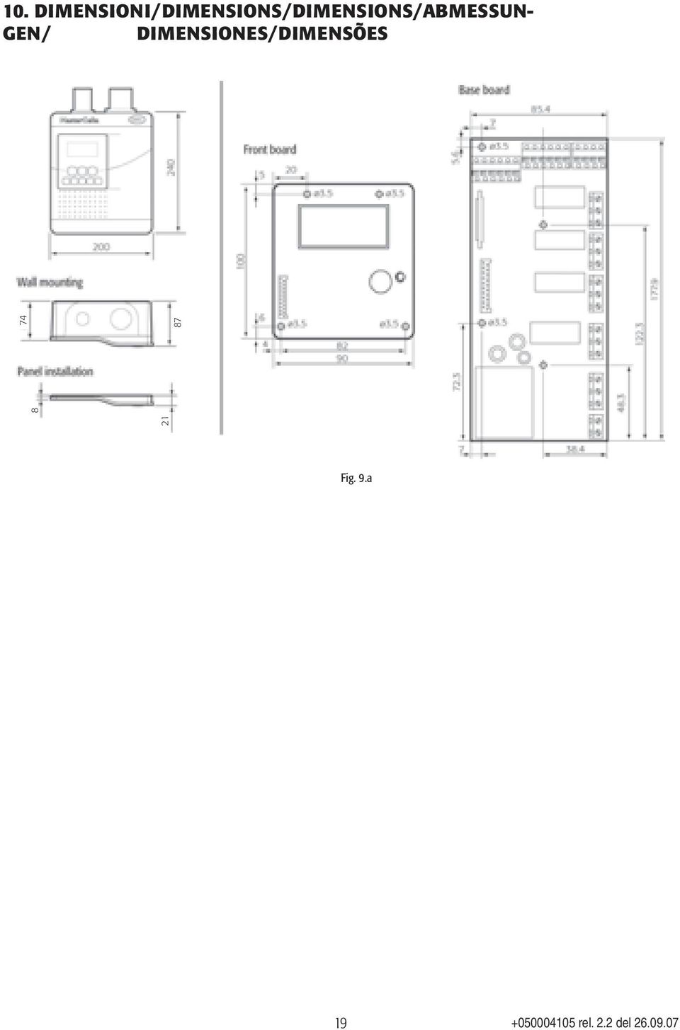
18 10. DIMENSIONI/DIMENSIONS/DIMENSIONS/ABMESSUN- GEN/ DIMENSIONES/DIMENSÕES Fig. 9.a 19
19 CAREL S.p.A. Via dell Industria, Brugine - Padova (Italy) Tel. (+39) Fax (+39) CAREL@CAREL.com - Agenzia/Agency rel

Features and Benefits
 Refrigeration 2 eatures and Benefits Based on IR32 Parameters Real Time lock ( RT ) Model Specific (defrost based on real time 7 day 24 hour) HAP (Hazard Analysis and ritical ontrol Point) Alarm Available
Operating ambient temperature range: 5ºC to 50ºC Storage temperature range: -30ºC to 70ºC
 HOJA TÉCNICA 1400H101 Edición 01 (02 de 08) www.ako.es GENERAL TECHNICAL SPECIFICATIONS Temperature range: -50ºC to +99ºC type: NTC Total accuracy ( + controller): ±1ºC lead extension with cable AKO-15586:
NL708 (XWA11V) Walk-In Temp / Door /Alarm / Light Module
 Walk-In Temp / Door /Alarm / Light Module") NL708 (XWA11V) Walk-In Temp / Door /Alarm / Light Module 1. General Description 1 2. General Warnings 1 3. Interface 2 4. Temp Alarms Setting 3 5. Programming 3 6. Light Management 4 7. Installation and
NL708 (XWA11V) Walk-In Temp / Door /Alarm / Light Module 1. General Description 1 2. General Warnings 1 3. Interface 2 4. Temp Alarms Setting 3 5. Programming 3 6. Light Management 4 7. Installation and
Application Engineering
 Application Engineering February 2011 Electronic Unit Controller Table of Contents 1. Introduction and Features... 2 1.1 Technical Specifi cations... 3 1.2 Pressure Probe Error Bypass... 3 1.3 Bump Start...
HVAC-32A. Operation Manual. Specifications. Digital Multistage Air Conditioning Controller with inbuilt Outside Air Economy function
 Specifications Supply Voltage 240VAC @ 0.07Amps or 24VAC @ 0.380Amps Relays 240V @ 12A max (resistive) / Comp1,2,3, Aux Ht, Rv O/B) Fuses (Equipment) 15 Amps Maximum 3AG Control Range Minus 10 to 50C Control
AC-115 Compact Networked Single Door Controller. Installation and User Manual
 AC-115 Compact Networked Single Controller Installation and User Manual December 2007 Table of Contents Table of Contents 1. Introduction...5 1.1 Key Features... 6 1.2 Technical Specifications... 7 2.
CONTENTS General features Front panel and buttons Installation List of the working parameters to be checked before starting the unit
 CONTENTS General features..... 1 Models available..... 1 Main features of the Infrared Series.... 2 Front panel and buttons..... 4 LED display Indicators..... 4 Keypad..... 5 Installation..... 6 Standard
Inwall Room Temperature Unit
 Inwall Room Temperature Unit TM11B01KNX TM11B11KNX TM11B21KNX Product Handbook Product: Inwall Room Temperature Unit Order Code: TM11B01KNX TM11B11KNX TM11B21KNX Application Program ETS: TM11B_1KNX Inwall
INSTALLATION OPERATING & MAINTENANCE MANUAL
 INSTALLATION OPERATING & MAINTENANCE MANUAL Basic Climatic TM Controller Ecologic English November 2002 CONTENTS PAGE GENERAL DESCRIPTION 3 USER INTERFACE 4 The keypad incorporated on the unit 4 The keypad
Controller for temperature control - EKC 102 REFRIGERATION AND AIR CONDITIONING. Manual
 Controller for temperature control - EKC 102 REFRIGERATION AND AIR CONDITIONING Manual Introduction Application The controller is used for temperature control refrigeration appliances and cold room Defrost
ECP 208. Cold Rooms Controllers USER S MANUAL
 ECP 208 Cold Rooms Controllers USER S MANUAL INDEX DESCRIPTION... 3 FUNCTIONING... 4 PARAMETERS SETTING... 4 FRONTAL SETTING CONTROLS... 4 MAIN FEATURES... 5 LAYOUT AND TERMINAL BLOCKS... 6 OPTIONS...
Digital controller with alarm management XR40CX
 1. CONTENTSGENERAL WARNING Digital controller with alarm management XR40CX 1.1 PLEASE READ BEFORE USING THIS MANUAL This manual is part of the product and should be kept near the instrument for easy and
T-100-R Installation Guide
 T-100-R Installation Guide Table of Contents Page 2 Overview T-100-R Z-Wave Thermostat 3-4 Installation HVAC System Setup 6 Installer Settings Menu Items 7-9 Installer Settings Summary 10-11 Wiring Standard
T5000 T000 LCD Digital Fan Coil Thermostat
 T5000 T000 LCD Digital Fan Coil Thermostat T000 LCD Digital Fan Coil Thermostat T000 LCD Digital Fan Coil Thermostats are designed to control heating, cooling, or year round air conditioning unit in Commercial,
User Manual THR840DUK Digital Thermostat
 User Manual THR840DUK Digital Thermostat 50051982-001 Rev. A WARNING: This product must be correctly installed and configured to work properly (see pages 12-24). If you are not experienced in wiring electrical
PD 100A. Printing data system
 PD 100A Printing data system Operating instructions ENGLISH IMPORTANT: Read these instructions carefully before installing and using the device; do not forget following all additional information. Keep
TEMON 8-C. Doc. N MO-0370-ING TEMPERATURE MONITOR DEVICE TYPE TEMON 8-C OPERATION MANUAL. Microener - Copyright 2010 FW 2.2 Date 01.12.2008 Rev.
 TEMPERATURE MONITOR DEVICE TYPE TEMON 8-C OPERATION MANUAL Microener - Copyright 2010 FW 2.2 Date 01.12.2008 Rev. 0 1. Generality 3 2. Introduction 3 3. Accessories and Options 3 4. Installation 3 5. Connection
TABLE 1: Wiring Terminals. Connect to... 1C 1H 2C 2H 1H1C 2H1C 2H2C 3H2C
 Installation TURN OFF POWER TO THE SYSTEM AT THE MAIN POWER PANEL TO AVOID ELECTRICAL SHOCK. Installation should be carried out by an electrician or a qualified technician. 1.1 Find a Location for the
Alpha Climatic Programmable Modulating Boiler Energy Manager. Installation and User Instructions
 Alpha Climatic Programmable Modulating Boiler Energy Manager Part No 3.022144 (Hard Wired) Part No 3.022143 (Radio Frequency) Installation and User Instructions 1. Description The Alpha Climatic energy
Electronic Control Devices The European Product Catalogue 2007
 FX14 Field Controller (1/4) FX14 Field Controller The FX14 is an equipment field controller in the Facility Explorer range of products. The controller is designed specifically for commercial Heating, Ventilating,
Electronic Control Devices The European Product Catalogue 2007
 FX07 Field Controller (1/4) FX07 Field Controller Display Model Dimensions in mm (inches) The FX07 is a terminal unit controller in the Facility Explorer range of products. The controller is designed specifically
TLK 48 MICROPROCESSOR-BASED DIGITAL ELECTRONIC REGULATOR
 TLK 48 MICROPROCESSOR-BASED DIGITAL ELECTRONIC REGULATOR TECHNICAL DATA CARATTERISTICHE MECCANICHE Housing Self-extinguishing plastic, UL 94 V0 Dimensions 48x48 mm DIN depth 98 mm Weight 225 g approx.
D755M CONTROL CARD FOR TWO SINGLE-PHASE MOTORS 220/230 VAC TARJETA DE MANDO PARA DOS MOTORES MONOFÁSICOS 220/230 VAC INSTALLATION GUIDE
 Distributed by: AFW Access Systems Phone: 305-691-7711 Fax: 305-693-1386 E-mail: sales@anchormiami.com D755M CONTROL CARD FOR TWO SINGLE-PHASE MOTORS 220/230 VAC TARJETA DE MANDO PARA DOS MOTORES MONOFÁSICOS
TC 1818a. Operating Guide. Control Module SWM-015.5
 TC 1818a Control Module Operating Guide SWM-015.5 This guide is intended solely for use by owners of Thermon HeatChek TM heat tracing control and monitoring units. This manual describes operation for TC
GSM HOME SECURITY SYSTEM
 Cell /Mobile phone home security system GSM HOME SECURITY SYSTEM Model : GSM-120 TABLE OF CONTENTS 1. FEATURES... 1 2. APPLICATION... 2 3. SPECIFICATIONS... 3 4. FRONT PANEL & LAYOUT DESCRIPTION...6 5.
RISH CON - Hz. Salient Features : Application : Product Features: FREQUENCY TRANSDUCER
 Application : The RISH CON - Hz transducer is used for frequency measurement. The output signal is proportional to measured frequency and is either load independent DC Current or load independent DC Voltage.
LINETRAXX VMD460-NA. Network and system protection (NS protection) for monitoring the power feed-in of power generation systems
 for monitoring the power feed-in of power generation systems") LIETRAXX -A etwork and system protection (S protection) for monitoring the power feed-in of power generation systems TDB301021en/06.2013 LIETRAXX -A etwork and system protection (S protection) for monitoring
LIETRAXX -A etwork and system protection (S protection) for monitoring the power feed-in of power generation systems TDB301021en/06.2013 LIETRAXX -A etwork and system protection (S protection) for monitoring
New generation......continuity, innovation, design
 ...continuity, innovation, design T e c h n o l o g y & E v o l u t i o n ...continuity, innovatio n, design Welcome to the new generation! The famous ir32 series of controllers has given rise to the new
HERZ-Thermal Actuators
 HERZ-Thermal Actuators Data Sheet 7708-7990, Issue 1011 Dimensions in mm 1 7710 00 1 7710 01 1 7711 18 1 7710 80 1 7710 81 1 7711 80 1 7711 81 1 7990 00 1 7980 00 1 7708 11 1 7708 10 1 7708 23 1 7709 01
Vertical Display and Storage B1350-2. SKOPE Gen2: Three Door Chiller
 Vertical Display and Storage User Manual MAN1227 Rev. 3.0 March 2008 edition CONTACT ADDRESSES Designed and Manufactured by New Zealand SKOPE INDUSTRIES LIMITED PO Box 1091, Christchurch New Zealand Freephone:
Monitoring Network DMN
 Monitoring Network DMN User Manual Table of contents Table of contents... 2 1. Product features and capabilities... 3 2. System requirements... 5 3. Getting started with the software... 5 3-1 Installation...
A.1. a Division of Pittway Corporation. Documento: M-010.1-MGAS-ENG. Edizione: 01/1997 Rev.:
 Documento: M-010.1-MGAS-ENG Edizione: 01/1997 Rev.: A.1 a Division of Pittway Corporation FRONT PANEL & VISUAL INDICATIONS GENERAL TROUBLE GENERAL PROGRAMMING IN PROGRESS ENABLE/ALARM/TROUBLE (ZONE 1 ALARM
Daker DK 1, 2, 3 kva. Manuel d installation Installation manual. Part. LE05334AC-07/13-01 GF
 Daker DK 1, 2, 3 kva Manuel d installation Installation manual Part. LE05334AC-07/13-01 GF Daker DK 1, 2, 3 kva Index 1 Introduction 24 2 Conditions of use 24 3 LCD Panel 25 4 Installation 28 5 UPS communicator
INSTALLATION GUIDE. Card Reader & Controller with KIM Swipe Reader for Solitaire 850 / 950 / 850L Learnlok PK2930
 INSTALLATION GUIDE Card Reader & Controller with KIM Swipe Reader for Solitaire 850 / 950 / 850L Learnlok PK2930 Card Reader and Controller Model 3.5 with KIM Swipe Reader Table of Contents 1. Features..................................
Regolatori per Refrigerazione Digitali FR... 1-2 canali
 Regolatori per Refrigerazione Digitali FR... 1-2 canali Manuale d Uso 1-2 Channel Regulators for Digital Refrigeration System Manuel Contents Safety warnings Page 20 Technical specifications Page 20 Description
SERVICE INSTRUCTION R410A. WALL MOUNTEDtype INVERTER SPLIT TYPE ROOM AIR CONDITIONER. Models Indoor unit Outdoor unit
 SERVICE INSTRUCTION SPLIT TYPE ROOM AIR CONDITIONER WALL MOUNTEDtype INVERTER Models Indoor unit Outdoor unit ASYG07LECA ASYG09LECA ASYG12LECA ASYG14LECA AOYG07LEC AOYG09LEC AOYG12LEC AOYG14LEC R410A CONTENTS
INSTALLATION MANUAL. Address card EKAC10B
 INSTALLATION MANUAL 88 44 µchiller compact 70 64 4a 4b G G0 power supply G G0 power supply 50 5 50 5 4a 4b 5a 5b 4 5a 5b Installation manual READ THIS MANUAL ATTENTIVELY BEFORE STARTING UP THE UNIT. DO
Fire Alarm Control Panel. Family. Operating Manual
 Fire Alarm Control Panel Family Operating Manual CONTENTS System Description AH-03312 System Characteristics... Fire Signal Receiving Board Description-4L... Fire Signal Receiving Board Description-8L...
its ELECTRIC POSITION for electric heat, or set the units fan control appropriately to ELECTRIC or another appropriate setting.
 Troubleshooting Poor Temperature Regulation This page lists problems that may affect the temperature performance of your LUX thermostat with suggested resolutions. For more detailed information please
Vroom Hardware manual ver. 1.00 Code 114VROOHWE00. Vroom CANBUS USER INTERFACE WITH LCD GRAPHIC DISPLAY AND WITH TEMPERATURE AND HUMIDITY SENSOR
 Vroom CANBUS USER INTERFACE WITH LCD GRAPHIC DISPLAY AND WITH TEMPERATURE AND HUMIDITY SENSOR ENGLISH HARDWARE MANUAL ver. 1.00 CODE 114VROOHWE00 page 1 of 22 Important Important Read these instructions
HCS-3300/3302/3304 USB Remote Programmable Laboratory Grade Switching Mode Power Supply
 1. INTRODUCTION HCS-3300/3302/3304 USB Remote Programmable Laboratory Grade Switching Mode Power Supply User Manual This family of efficient, upgraded SMPS with small form factor, auto cross over CV CC,
Monitoring,Telemaintenance,... HACCP. Innovative Supermarket solutions. Tecnologia ed Evoluzione
 Monitoring,Telemaintenance,... HACCP Innovative Supermarket solutions Tecnologia ed Evoluzione For more compact systems, with the same management and control needs as larger areas, PlantWatch offers the
COMPUTHERM Q7 Programmable, digital room thermostat. Operating Instructions
 COMPUTHERM Q7 Programmable, digital room thermostat Operating Instructions GENERAL DESCRIPTION OF THE THERMOSTAT The COMPUTHERM Q7 type switched-mode room thermostat is suitable to regulate the overwhelming
ETC TWO STAGE ELECTRONIC TEMPERATURE CONTROL
 RANCO INSTALLATION INSTRUCTIONS ETC TWO STAGE ELECTRONIC TEMPERATURE CONTROL Relay Electrical Ratings PRODUCT DESCRIPTION The Ranco ETC is a microprocessor-based family of electronic temperature controls,
SMM. Installation Operation Maintenance
 SMM Configuration SMM Module for Scroll Units, H Generation Installation Operation Maintenance 1 0 L80 IM 022 GB SMM Configuration SMM Module for Scroll Units, H generation Foreword These installation,
HAM841K ALARM CONTROL PANEL FOR COMMERCIAL AND RESIDENTIAL SECURITY SYSTEMS
 ALARM CONTROL PANEL FOR COMMERCIAL AND RESIDENTIAL SECURITY SYSTEMS USER MANUAL USER MANUAL ALARM CONTROL PANEL FOR COMMERCIAL AND RESIDENTIAL SECURITY SYSTEMS INTRODUCTION The (HA-841K) is a complete
MTS Power Products MIAMI FL 33142 ATS-22AG. Automatic Transfer Switch And Control PLC Operator s Manual
 MTS Power Products MIAMI FL 33142 ATS-22AG Automatic Transfer Switch And Control PLC Operator s Manual Dedicated Single Phase Transfer Switch With Touch Screen Controls Normal Power Connections Emergency
PLC Control Unit for a CSM-C Steam Compact Clean Steam Generator
 3.635.5275.251 IM-P486-19 CH Issue 2 PLC Control Unit for a CSM-C Steam Compact Clean Steam Generator Installation, Start-up and Operation Manual 1. Safety information 2. General product information 3.
Aerona Air Source Heat Pumps
 ADDENDUM to INSTALLATION INSTRUCTIONS for Aerona Air Source Heat Pumps DOC.87-05/05 Rev.04 March 2013 ATTENTION INSTALLERS - UPDATED INFORMATION! Your Grant Aerona Air Source Heat Pump has a number of
KRONOS GA11 WEEKLY-PROGRAMMING DIGITAL CHRONOTHERMOSTAT FOR THE REMOTE CONTROL OF HOT AIR GENERATORS THROUGH BRAHMA INTERFACE BOARD APPLICATION
 KRONOS GA11 WEEKLY-PROGRAMMING DIGITAL CHRONOTHERMOSTAT FOR THE REMOTE CONTROL OF HOT AIR GENERATORS THROUGH BRAHMA INTERFACE BOARD APPLICATION The digital chronothermostat Brahma Kronos series integrates
Service manual. Website: www.andico.com.au CAUTION - BEFORE SERVICING THE UNIT, READ THE SAFETY - PRECAUTIONS IN THIS MANUAL.
 Website: www.andico.com.au Service manual CAUTION - BEFORE SERVICING THE UNIT, READ THE SAFETY - PRECAUTIONS IN THIS MANUAL. - ONLY FOR AUTHORISED SERVICE PERSONNEL. MODELS: MPK1-09CR-QB8 MPK1-12ER-QB6
FLOW CALCULATOR INSTRUCTION MANUAL MESURES BAMOPHOX 759 26-06-2007 759 M1 02 E MES FLOW CALCULATOR 759-02/1
 BAMOPHOX 759 E - M FLOW CALCULATOR INSTRUCTION MANUAL MESURES 22, Rue de la Voie des Bans - Z.I. de la Gare - 95100 ARGENTEUIL Tél : (33) 01 30 25 83 20 - Web : www.bamo.fr Fax : (33) 01 34 10 16 05 -
1 Introduction...3 2 General Description...3. 2.1 Functions... 3 2.2 Main Board... 3 2.3 Second compressor board... 4. 3 User Interface (Terminal)...
...") LCA - LCW - LCR Water chillers and heat pumps USER MANUAL GB INDICE 1 Introduction...3 2 General Description...3 2.1 Functions... 3 2.2 Main Board... 3 2.3 Second compressor board... 4 3 User Interface
LCA - LCW - LCR Water chillers and heat pumps USER MANUAL GB INDICE 1 Introduction...3 2 General Description...3 2.1 Functions... 3 2.2 Main Board... 3 2.3 Second compressor board... 4 3 User Interface
Automation System TROVIS 5100 Ventilation Controller TROVIS 5177
 Automation System TROVIS 5100 Ventilation Controller TROVIS 5177 ounting and Operating Instructions EB 5177 EN Electronics from SASON Firmware version 1.05 Edition September 2000 Contents 1 Scope of the
BARDIC. 4 & 8 Zone Fire Panels Zircon range. Data, installation, operation and maintenance. by Honeywell
 Data, installation, operation and maintenance 4 & 8 Zone Fire Panels Zircon range BARDIC by Honeywell LED flashing LED Continuous FAULT DISABLE/TEST Power General Fault Sounder Fault/ Disable System Fault
GREISINGER electronic GmbH
 T38.0.0X.6C-03 CO2 - Transmitter Operating Manual GT10 - CO2-1R GREISINGER electronic GmbH D - 93128 Regenstauf, Hans-Sachs-Straße 26 Tel.: +49 9402 / 9383-0, Fax: +49 9402 / 9383-33, email: info@greisinger.de
MILLENIUM INSTALLATION MANUAL NTR 735 A. Simple Automation Control Module (MAS)
") MILLENIUM Table of contents 1. INTRODUCTION 1 2. HARDWARE DESCRIPTION 2 3. INSTALLATION 5 4. CONNECTION 6 5. USER SAFETY AND PROTECTION OF EQUIPMENT 8 1. Introduction The MILLENIUM series has been designed
MILLENIUM Table of contents 1. INTRODUCTION 1 2. HARDWARE DESCRIPTION 2 3. INSTALLATION 5 4. CONNECTION 6 5. USER SAFETY AND PROTECTION OF EQUIPMENT 8 1. Introduction The MILLENIUM series has been designed
SERVICE INSTRUCTION R410A. WALL MOUNTEDtype SPLIT TYPE ROOM AIR CONDITIONER INVERTER. Models Indoor unit Outdoor unit AOU 9RLFW AOU12RLFW AOU15RLS
 SERVICE INSTRUCTION SPLIT TYPE ROOM AIR CONDITIONER WALL MOUNTEDtype INVERTER Models Indoor unit Outdoor unit ASU 9RLF ASURLF ASU5RLS AOU 9RLFW AOURLFW AOU5RLS R40A CONTENTS. DESCRIPTION OF EACH CONTROL
PRONET WEB SERVER. INSTRUCTIONS FOR INSTALLATION AND USE English. Version 01/15 Ident no. 50950129
 PRONET WEB SERVER INSTRUCTIONS FOR INSTALLATION AND USE English EN Version 01/15 Ident no. 50950129 Table of Contents 1. About these instructions 3 2. Important information for your safety 4 2.1. Intended
RZAHUC program version 1.1 Regulation for Reznor Air Handling Units
 INSTALLATION INSTRUCTIONS OPTION 1xxx 1104_1000_EN Comfort Regulation (Carel pco) Detailed instructions RZAHUC program version 1.1 Regulation for Reznor Air Handling Units INDEX 1. Introduction... 4 1.1.
UM-X Field display for continous level sensors
 Technical Documentation Field display for continous level sensors 10/2007 Edition: 1 Item No.: 207120 FAFNIR GmbH Bahrenfelder Str. 19 D-22765 Hamburg Telephone: +49 (0)40-39 82 07-0 Fax: +49 (0)40-3 90
543-0032-00, 943-0032-00. User s Manual
 543-0032-00, 943-0032-00 User s Manual 1 Comfort Alert Diagnostics Faster Service And Improved Accuracy The Comfort Alert diagnostics module is a breakthrough innovation for troubleshooting heat pump and
USER MANUAL WARNING! CONTENTS MODEL 1 SPECIFICATIONS READ ALL INSTRUCTIONS BEFORE PROCEEDING. Non-Programmable Single Stage Heat/Cool Thermostat
 Builder MODEL 1010 Series Non-Programmable Single Stage Heat/Cool Thermostat USER MANUAL Compatible with low voltage single stage gas, oil or electric heating or cooling systems, including single stage
RRV934. Multi-controller. Synco living
 s 2 709 Synco living Multi-controller RRV934 RF-based multi-controller For precontrol of up to 2 room groups For control of ventilation plant with up to 3 stages RF communication based on KNX standard
DALI RC BASIC SO. Control unit Operating instructions
 DALI RC BASIC SO Control unit Operating instructions Contents Safety... 4 General instructions 4 Safety instructions 4 Description... 5 Purpose and application 5 Function 5 Light control 5 Brightness
Automation System TROVIS 6400 TROVIS 6493 Compact Controller
 Automation System TROVIS 6400 TROVIS 6493 Compact Controller For panel mounting (front frame 48 x 96 mm/1.89 x 3.78 inch) Application Digital controller to automate industrial and process plants for general
Conventional Fire Detection and Extinguishant Control System Specification
 Conventional Fire Detection and Extinguishant Control System Specification Page 1 of 9 Scope Furnish a complete 24VDC Conventional, electrically supervised, combined fire detection and extinguishant release
SERVICE MANUAL REFRIGERATION
 SERVICE MANUAL REFRIGERATION ELECTROLUX HOME PRODUCTS S.p.A. Publication no. Spares Operations Italy 599 36 16-90 Corso Lino Zanussi, 30 031117 I - 33080 PORCIA / PN (ITALY) ITZ/SERVICE/AA Fax +39 0434
PK5500 v1.1 Installation Instructions
 PK5500 v1.1 Installation Instructions 1 2 3 4 5 6 7 8 9 * 0 # WARNING: Please refer to the System Installation Manual for information on limitations regarding product use and function and information on
Match. GE Digital Energy. Uninterruptible Power Supply 500-1500 VA. Technology for the Digital World. Match UPS. GE Digital Energy.
 Match Uninterruptible Power Supply 500-1500 VA Manufactured by: General Electric Company Telephone +41 (0)91 / 850 51 51 CH 6595 Riazzino (Locarno) Fax +41 (0)91 / 850 51 44 Switzerland Website www.gedigitalenergy.com
Technical Support Bulletin Nr. 11 Alarms Codes
 Technical Support Bulletin Nr. 11 Alarms Codes Contents! Introduction! Alarm Tables Index! Alarm Tables Introduction This document describes all the error messages that display on devices for commercial
pco 2 Standard Application Pack Control Code: FLSTDMFC0A Version 1.2 s manual
 pco 2 Standard Application Pack Control Code: FLSTDMFC0A Version 1.2 s manual We wish to save you time and money! We can assure you that the thorough reading of this manual will guarantee correct installation
MOUNTING AND OPERATING INSTRUCTIONS
 MOUNTING AND OPERATING INSTRUCTIONS CF 51/55 1. Delivery CF 51/55-1 calculator with battery (optionally with mains power supply) - 1 wall mounting bracket - package with material for sealing, screws, wall
Programmable Thermostat MODEL 3312026.XXX With Dehumidify 3312024.XXX With Out Dehumidify
 Comfort Control Center 2 Thermostat Operating Instructions Programmable Thermostat MODEL 3312026.XXX With Dehumidify 3312024.XXX With Out Dehumidify TABLE OF CONTENTS About your new thermostat Features...2
Introduction. Refrigerant Leak Detecting System. Feature and Benefits
 PSC European Refrigeration Controls Catalogue Catalog Section 9 Product Bulletin PD-GAS-E Refrigerant Leak Detecting System Introduction This range of refrigerant leak detecting systems is designed for
HP 5 Microprocessor Control for Mammoth Water Source Heat Pumps
 HP 5 Microprocessor Control for Mammoth Water Source Heat Pumps Operation and Maintenance Manual Model: 71028004 Applies to: Single Circuit Water-to-Water Twin Circuit Units Without DDC Controls MAMM WHSP
Input signal Maximum Range Accuracy. Thermocouple E -50 to 700 C (-58 to 1832 F) ±1 C
 ±1 C") F4 Process Controller Installation and Operation Guide SAFETY ALERTS The symbols below are used on the equipment and throughout this document to draw the user s attention to important operational and safety
F4 Process Controller Installation and Operation Guide SAFETY ALERTS The symbols below are used on the equipment and throughout this document to draw the user s attention to important operational and safety
Online UPS. PowerWalker VFI 1000R/1U
 Online UPS PowerWalker VFI 1000R/1U Manual Uninterruptible Power Supply System Table of Contents 1. Important Safety Warning... 1 1-1. Transportation... 1 1-2. Preparation... 1 1-3. Installation... 1 1-4.
with MERCURY FREE 1 HP Relays ! WARNING Before using this product read and understand instructions.
 B Installation & Maintenance Instructions MM-414 Series 150E and 157E Low Water Cut-Off/Pump Controllers For Steam Boilers and Other Level Control Applications A Typical Applications: Primary or secondary
FX07 Field Controller
 Product Bulletin FX07 Field Controller Issue Date March 25, 2008 FX07 Field Controller The FX07 is a high performance field controller designed specifically for commercial Heating, Ventilating, Air Conditioning,
Technical Information
 Date of last update: Oct-11 Ref: D7.8.4/1011/E Application Engineering Europe CORESENSE DIAGNOSTICS FOR STREAM REFRIGERATION COMPRESSORS CoreSense Diagnostics for Stream Refrigeration Compressors... 1
User manual. Application program for pco 1, pco 2, pco 3. Standard Chiller Modular HP 1/4 Generic /Bitzer screw compressor and CAREL valve
 Standard Chiller Modular HP 1/4 Generic /Bitzer screw compressor and CAREL valve Application program for pco 1, pco 2, pco 3 User manual Manual Version: 1.4 dated 11/09/08 Program code: FLSTDmMSBE LEGGI
TMS TANK MANAGEMENT SYSTEM
 TMS TANK MANAGEMENT SYSTEM Page 1 of 9 Operating Instructions GENERAL The Tank Management System is a bespoke design to control, monitor and accommodate efficient storage and dispensing of TMS. FUNCTIONS
SERVICE MANUAL FOR 6535 SERIES TWO TON HIGH EFFICIENCY PACKAGED HEAT PUMPS
 SERVICE MANUAL FOR 6535 SERIES TWO TON HIGH EFFICIENCY PACKAGED HEAT PUMPS TABLE OF CONTENTS 1. Warnings...2 2. Accessibility Of Appliance...3 3. Unit Dimensions And Specifications...3 4. Unit Specifications
How To Program An Autodialer
 GJD HYL005 GSM Autodialer Instruction Manual Please read these instructions before you start the installation Features: LCD display. Programmable 9 x 32 digit phone numbers for each trigger. 10 second
Installation Guide. LR-HWLV-HVAC TouchPRO Wireless. System Types
 Installation Guide LR-HWLV-HVAC TouchPRO Wireless Touchscreen Thermostat System Types Gas, oil, or electric heat with air conditioning Warm air, hot water, high efficiency furnaces, heat pumps, steam,
is then retained absolutely without interruption.
 Page 1 of 11 DC UPS uninterruptible power supplies - DC UPS module 15 A Compact design, only 50 mm wide Absolutely interruption-free buffering of power failures through immediate electronic connection
F453. TiF453. User guide 10/11-01 PC
 F453 TiF453 User guide 10/11-01 PC 2 TiF453 User guide Contents 1. Hardware and Software requirements 4 2. Installation 4 1.1 Minimum Hardware requirements 4 1.2 Minimum Software requirements 4 3. Fundamental
Fixed - Over/Under voltage limits, (0.75...1.2) U N respectivity Link selectable - 5 min or 10 min delay. Fixed limits
 U N respectivity Link selectable - 5 min or 10 min delay. Fixed limits") Features 71.11.8.230.0010 71.11.8.230.1010 1 - Phase 230 V Over & Under voltage monitoring relays 71.11.8.230.0010 - Fixed Over & Under voltage detection - Link selectable 5 or 10 minute lock-out delay
Features 71.11.8.230.0010 71.11.8.230.1010 1 - Phase 230 V Over & Under voltage monitoring relays 71.11.8.230.0010 - Fixed Over & Under voltage detection - Link selectable 5 or 10 minute lock-out delay
Firmware version: 1.10 Issue: 7 AUTODIALER GD30.2. Instruction Manual
 Firmware version: 1.10 Issue: 7 AUTODIALER GD30.2 Instruction Manual Firmware version: 2.0.1 Issue: 0.6 Version of the GPRS transmitters configurator: 1.3.6.3 Date of issue: 07.03.2012 TABLE OF CONTENTS
SERVICE INSTRUCTION R410A. SPLIT TYPE ROOM AIR CONDITIONER Universal Floor / Ceiling Duct / Cassette Wall Mounted / Floor type INVERTER MULTI
 SERVICE INSTRUCTION SPLIT TYPE ROOM AIR CONDITIONER Universal Floor / Ceiling Duct / Cassette Wall Mounted / Floor type INVERTER MULTI R410A Models Indoor unit Outdoor unit AB*14LBAJ AB*18LBAJ AB*F14LAT
Owner s Guide Guide du propriétaire Guía para el usuario TH115-AF-GB-10. Programmable thermostat Thermostat programmable Termostato programable
 Owner s Guide Guide du propriétaire Guía para el usuario TH115-AF-GB-10 Programmable thermostat Thermostat programmable Termostato programable Read and save these instructions. Veuillez lire le mode d
HEAT HEAT COOL HEAT PUMP COOL
 OWNER S MANUAL RESIDENTIAL THERMOSTAT P/N P374-1800 HEAT COOL HEAT PUMP Su AUTO 0I20: Pm 74 COOL HEAT 27 7-DAY MABLE DIGITAL THERMOSTAT 3 Configurable Outputs Accepts Optional Humidity Module: Control
Porcia, 20 novembre 2012
 1 2 PLZ RANGE 14-18-20 3 TECHNICAL NUMBERS 4 MAIN COMPONENTS CONTROL SAFETY HYDRONIC OUTLET WATER TEMPERATURE INLET WATER TEMPERATURE AIR OR WATER EXTERNAL TEMPERATURE FRESH AIR WITH PRESSURE DIFFERENTIAL
0.8 U N /0.5 U N 0.8 U N /0.5 U N 0.8 U N /0.5 U N 0.2 U N /0.1 U N 0.2 U N /0.1 U N 0.2 U N /0.1 U N
 55 Series - General purpose relays 7-10 A Features 55.12 55.13 55.14 Printed circuit mount, general purpose 2, 3 & 4 Pole relays 55.12-2 Pole 10 A 55.13-3 Pole 10 A 55.14-4 Pole 7 A AC coils & DC coils
Automation and Systems Technology. LABCONTROL TFM/TPM User Manual TroxMConnect Operating Software. 1. Introduction 1. 2. Software Installation 2
 1. Introduction 1 2. Software Installation 2 2.1 System Requirements 2 2.2 TroxMConnect Installation 2 2.3 Connection to the PC 3 3. TroxMConnect Description 4 3.1 Starting the Software 4 3.2 Layout 4
Energy Division http://energy.tycoelectronics.com
 Energy Division http://energy.tycoelectronics.com Installation and Operating Instructions GEN-AUTO FP Tyco Electronics UK Limited Crompton Instruments Freebournes Road, Witham, Essex, CM8 3AH, UK Tel:
USER S MANUAL HSC-24A
 AIRREX AIR CONDITIONER USER S MANUAL HSC-24A Thank you for purchasing an AIRREX AIR CONDITIONER. BEFORE operation please read this user s manual carefully. Keep this manual readily available. It is ESSENTIAL
STERILIZERS, LABORATORY DRYING OVENS
 TS9026 TS9053 TS9135 TS9430 TS 9000 SERIES: STERILIZERS, LABORATORY DRYING OVENS Series TS9000 consists of four different cabinets available in sizes from 26 litres to 430 litres. Interior housing and
CONCIERGE SWITCHBOARD
 SECTION 4D CONCIERGE SWITCHBOARD Download from www.urmet.com Technical Manuals area. INDICE DI SEZIONE Ref. 1083/40 2 LIST OF DETAILS...2 Keypad...2 Ringer...2 Display...2 DESCRIPTION OF CONNECTIONS...2