Cement-retained crowns and bridges with the solid abutment system. Straumann Solid Abutment Prosthetic System
|
|
|
- Stuart Whitehead
- 9 years ago
- Views:
Transcription
1 Cement-retained crowns and bridges with the solid abutment system Straumann Solid Abutment Prosthetic System

2 The ITI (International Team for Implantology) is academic partner of Institut Straumann AG in the areas of research and education.

3 Contents Restoring implants with solid abutments and constructing the superstructure Introduction Indication, features and benefits 2 Who is who in the solid abutment system 3 Auxiliary parts required 4 Instructions for the dentist Placing the abutment 6 Taking the impression: Option A (non-modified abutments) 8 Taking the impression: Option B (modified abutments) 10 Temporary restoration 12 Instructions for the dental technician Constructing the superstructure: Option A (non-modified abutments) 14 Constructing the superstructure: Option B (modified abutments) 21 1
 14 Constructing the superstructure: Option B (modified")
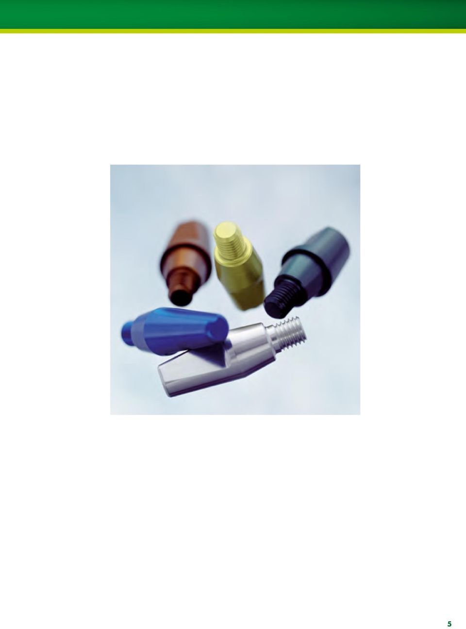
4 Introduction Indications Solid abutments can be used in both anterior and posterior areas of the mouth for cement-retained crown and bridge restorations. The insertion depth of the implant should allow easy access for the removal of excess cement. The restoration is very similar to the conventional method for fabricating crowns and bridges. The superstructure is manufactured by the dental technician and cemented in the mouth by the dentist or prosthodontist. Features and Benefits Reliable Morse taper connection for a secure frictional fit High strength due to solid one-piece structure High quality prosthetic components supported by decades of success Simple Prefabricated impression components to precisely transfer the oral situation Color-coded components for identification purposes Easy fixation of the superstructure Versatile Restorations for NNC*, RN and WN implants Abutments can be modified to fit individual needs For crowns and bridges Various temporary restorations available The impression-taking procedure in the dental practice and the construction of the superstructure in the dental laboratory depend on whether or not the abutment was modified. The following techniques are possible: Option A = Non-modified abutments Option B = Modified abutments * For information on the NNC solid abutment, please see brochure 15x.808 Prosthetic Procdures for the Narrow Neck CrossFit Implant. 2

5 Who is who in the solid abutment system RN (Regular Neck) Ø 4.8 mm WN (Wide Neck) Ø 6.5 mm Transfer parts V V /061/062V /066 Analogs /161/ V / Prosthetic restoration cement-retained Case planning (only V4) /927/928V V V4 Abutments Temporary restoration/ Protective caps / /048/049V / /052 Plastic copings Crown Bridge 3

6 Auxiliary parts required Parts for the dentist Art. No. Article /401/402 SCS screwdriver for ratchet /411/412 SCS screwdriver for handpiece /068 Solid abutment driver Ratchet Torque control device Holding key Parts for the dental technician Art. No. Article Guide pin for reamer , for RN solid abutment copings Guide pin for reamer , for WN solid abutment copings Reamer for 45 neck Handle for reamer 4

7 5
8 Placing the abutment Procedure Initial situation The pictures on the right shows a Standard implant Ø 4.1 mm (Regular Neck Ø 4.8 mm) in position 44 (28) and a Standard implant Ø 4.8 mm (Wide Neck Ø 6.5 mm) in position 46 (30). Following successful osseointegration, the implants can be restored. Remove any debris from the head of the healing caps and use any length SCS screwdriver to loosen, lift, and remove them. The internal aspect of the implants must then be throroughly cleaned and dried. Standard Implant Regular Neck in situ Standard Implant Wide Neck in situ RN (Regular Neck Ø 4.8 mm) WN (Wide Neck Ø 6.5 mm) 1. RN solid abutments ( / 541/542) are inserted using a solid 1 RN solid abutment driver for use with RN solid abutments SCS screwdriver for use with WN solid abutments abutment driver ( /068). The WN solid abutments ( / 546) are inserted using an SCS screw- Indicator for internal wedge driver ( /401/402/410/ 411/412). Working outside of the mouth and over a sterile field, align the groove of the groove RN solid abutment with the line on the driver shaft and insert the abutment into the driver. (When placing WN solid RN solid abutment for use with implants that have an RN Ø 4.8 mm restorative platform WN solid abutment for use with implants that have an WN Ø 6.5 mm restorative platform abutments, an SCS screwdriver is used instead. The star configuration of the screwdriver tip connects to the occlusal opening of the abutment, allowing it to be picked up.) Bring the abutment to the mouth with the appropriate driver Tightening torque = 35 Ncm and insert it into the implant. Use finger pressure to tighten it down. 6
 WN (Wide Neck Ø 6.5 mm) 1. RN solid abutments (048.")
9 Placing the abutment Procedure 2. Place the looped-end of the assembled ratchet with torque control device over the driver handle. The directional arrow must be pointing clockwise (towards the torque bar with tear drop). If it s not, simply pull the arrow out, flip it over, and push it back in. 2 The solid abutments are inserted into the implant without applying cement. Once the impression has been taken, any removal or repositioning of the abutment will require a new impression to capture the change in location of the flat side. 3. For stabilization, place the pin-end of the holding key into the coronal hole on the driver handle. 3 Therefore, once an abutment is torqued in, it should not be removed after the impression is taken. 4. Use one hand to hold the holding key and use the other hand to hold the torque bar. Grasp only the tear drop and move the torque bar to the 35 Ncm mark After reaching the 35 Ncm mark, return the torque bar to its starting position. Lift and remove the holding key, ratchet with torque control device, and the driver. The solid abutment is now in place and ready for the impression to be taken. Once the abutment has been torqued in, it should not be removed. 5 Tightening torque = 35 Ncm 7

10 Taking the impression: Option A (non-modified abutments) Overview Color-coding In order to facilitate identification, the transfer system is color-coded. Initial situation An RN and a WN solid abutment were inserted into the implants and torqued to 35 Ncm (see the description on pages 6 7). Accessories for RN solid abutment, height 4.0 mm = yellow Accessories for RN solid abutment, height 5.5 mm = grey Accessories for RN solid abutment, height 7.0 mm = blue Accessories for WN solid abutment, height 4.0 mm = green Accessories for WN solid abutment, height 5.5 mm = brown Impression taking step-by-step For implants with RN Ø 4.8 mm For implants with WN Ø 6.5 mm Step 1 Place the impression cap over the abutment and snap it onto the implant shoulder. Slightly rotate the cap to ensure that it is properly seated. Step 2 Push the positioning cylinder through the impression cap, taking care to align the internal flat side of the positioning cylinder with the flat side of the solid abutment. Push it until it is flush with the impression cap. Step 3 Take the impression and send it to the lab. RN solid abutments /541/542 RN impression cap V4 RN positioning cylinder V4/061V4/062V4 WN solid abutments /546 WN impression cap WN positioning cylinder /066 Note: All parts of the solid abutment transfer system are supplied non-sterile. The parts can be disinfected as required using standard commercial disinfection agents for plastic products (refer to the manufacturer s instructions). Caution: The plastic components are for single use only. They must not be sterilized. In order to prevent any damage to the plastic components (loss of elasticity or embrittlement) they must be protected from strong light or heat irradiation. 8

11 Taking the impression: Option A (non-modified abutments) Procedure 1. Place the impression cap Both the implant shoulder and the abutment must be cleaned of any blood or tissue prior to the impression procedure. If a WN solid abutment is used, the occlusal opening of the abutment must be sealed with wax or guttapercha. In order to avoid errors during the impression procedure, it must be ensured that the shoulder and the margin of the impression cap are not damaged. The RN impression cap ( ) or the WN impression cap ( ) is pushed over the abutment, and onto the implant shoulder, until the cap clicks into place. The impression cap is turned gently in order to check that it is securely snapped onto the implant shoulder. When the cap is seated correctly, it can be rotated smoothly on the implant. click click 2. Insert the positioning cylinder Positioning cylinders have a flat-side indicator (external knob) to identify where the internal flat side is. Care should always be taken to align the flat side of the positioning cylinder with the flat side of the abutment. It is then pushed down over the abutment and through the impression cap. The positioning cylinder must be pushed down as far as it will go, until it is flat and flush against the impression cap. 3. Take the impression The impression is taken using an elastomeric impression material (polyvinylsiloxane or polyether rubber). No gap Due to its insufficient tensile strength, hydrocolloid is not suitable for this application. 9

12 Taking the impression: Option B (modified abutments) Overview Initial situation It is sometimes necessary to modify the shape or size of a solid abutment. A different impression procedure must be used in such cases. In this case, an RN solid abutment was inserted into the implant and torqued to 35 Ncm (see the description on pages 6 7). Then the solid abutment was modified in the patient s mouth by the dentist using an appropriate grinding wheel with sufficient irrigation. To help ensure proper stability and retention of the restoration, the solid abutment must maintain a minimum height of 3.0 mm. Steps in impression-taking For implants with RN Ø 4.8 mm For implants with WN Ø 6.5 mm RN solid abutments /541/542 WN solid abutments /546 Step 1 Place the impression cap over the abutment and snap it onto the implant shoulder. Slightly rotate the cap to ensure that it is properly seated. RN impression cap V4 WN impression cap Step 2 Inject impression material through the holes of the impression cap, and take the impression. Send it to the lab. Note: All parts of the solid abutment transfer system are supplied non-sterile. The parts can be disinfected as required using standard commercial disinfection agents for plastic products (refer to the manufacturer s instructions). Caution: The plastic components are for single use only. They must not be sterilized. In order to prevent any damage to the plastic components (loss of elasticity or embrittlement) they must be protected from strong light or heat irradiation. 10

13 Taking the impression: Option B (modified abutments) Procedure In order to avoid errors during the impression procedure, it must be ensured that the shoulder and the margin of the impression cap are not damaged. click 1. Place the impression cap Both the implant shoulder and the abutment must be cleaned of any blood or tissue prior to the impression procedure. If a WN solid abutment is used, the remaining occlusal opening of the abutment must be sealed with wax and guttapercha. The RN impression cap ( ) or the WN impression cap ( ) is pushed over the abutment, and onto the implant shoulder, until the cap clicks into place. The impression cap is turned gently in order to check that it is securely snapped onto the implant shoulder. When the cap is seated correctly, it can be rotated smoothly on the implant Take the impression Impression material is injected through the occlusal and lateral openings and an impression is taken. An elastomeric impression material (polyvinylsiloxane or polyether rubber) is used for the impression procedure. Send it to the lab. 2 Due to its insufficient tensile strength, hydrocolloid is not suitable for this application. 11
 is pushed over the abutment, and onto the implant shoulder, until the cap clicks into place.")
14 Temporary restoration Procedure While the superstructure is being fabricated, the solid abutments must be temporized in some fashion. Keeping them covered will be more comfortable for the patient and also keep the abutments clean. The use of temporary plastic copings ( /655/656/657) is recommended for the fabrication of crowns and small temporary bridges for creating an ideal emergence profile. If the temporary restoration is intended only as a protective measure, protective caps ( /048/049/051/052) are ideal as an interim solution. Initial situation An RN solid abutment was inserted into the implant and torqued to 35 Ncm (see the description on pages 6 7). The impression is taken next, after which the abutment can be temporarily restored. A) Restoration with temporary copings 1. Mark the appropriate height of the provisional restoration and modify the coping accordingly Snap the temporary coping onto the corresponding analog and mark the appropriate height according to the individual clinical situation and the abutment used. The coping can then be shortened as necessary, using the vertical retention rings of the coping as a guide. Do not use Vaseline (aliphatic isolation agent) for insulation of the abutment Fabricate the provisional restoration If necessary, you can modify the margin of the coping. Then snap the temporary coping onto the implant shoulder and create the provisional restoration on the temporary coping according to standard techniques (e.g. prefabricated polycarbonate crowns or vacuum stents). The retention rings ensure proper mechanical bonding of the veneering material to the coping. The plateau of the coping helps to prevent the veneering material from flowing under the implant shoulder. 2 12
 are ideal as an interim solution.")
15 Temporary restoration 3. Finalize fabrication of the provisional restoration Remove the provisional restoration/temporary coping and place it back onto the analog. Grind down and polish the emergence profile of the coping and the restoration to achieve an even profile. To avoid tissue irritation, it is important to finish the interface until it s smooth and the coping is flush with the restoration. The restoration must always be out of occlusion Remove the snap-on mechanism Remove the lip of the snap-on mechanism from the temporary coping by using the reamer instrument or a hand piece/rubber wheel. It is mandatory to remove the lip of the snap-on mechanism to allow proper extrusion of excess cement Cement the provisional restoration onto the abutment Apply temporary cement to the inner part of the coping, and cement it onto the abutment and the implant shoulder. Temporary copings must be attached with temporary cement. Adequate and secure attachment is only provided by the use of temporary cement. Note: Temporary copings must not be kept in the mouth longer than 30 days Use conventional techniques to remove the temporary coping with the attached provisional restoration (see package insert). To prevent abutment shifting, provisional restorations must not be removed with rotational movements. B) Restoration with protective caps Only temporary cement should be used to secure the protective caps. Protective caps are removed the same way as a temporarily cemented crown. In order to prevent any displacement of the abutment, the protective cap must not be removed using a rotary movement. 13

16 Constructing the superstructure: Option A (non-modified abutments) Overview Initial situation An RN and a WN solid abutment were inserted into the implants by the dentist and torqued to 35 Ncm (see the description on pages 6 7). The abutments were not modified. Then the impression was taken (pages 8 9) and sent to the dental laboratory. Steps in construction Step 1 Select the appropriate analog. Align the flat side of the analog with the flat side of the positioning cylinder (captured in the impression). Insert the analog into the impression until it snaps ( clicks ) securely into place. Pour up in stone (extra hard stone, type 4). For implants with RN Ø 4.8 mm RN analogs /161/162 For implants with WN Ø 6.5 mm WN analogs /166 Step 2 Select the appropriate coping (crown/bridge) and snap it ( click ) over the analog. Trim the height as necessary. Step 3 The framework is then modeled in the usual way. RN plastic copings /246 crown/bridge WN plastic copings /248 crown/bridge Step 4 After fabrication, the final restoration is delivered to the doctor. It is placed over the solid abutment with permanent cement. Note: All parts of the solid abutment transfer system are supplied non-sterile. The parts can be disinfected as required using standard commercial disinfection agents for plastic products (refer to the manufacturer s instructions). Caution: The plastic components are for single use only. They must not be sterilized. In order to prevent any damage to the plastic components (loss of elasticity or embrittlement) they must be protected from strong light or heat irradiation. 14
. For implants with RN Ø 4.8 mm RN analogs 048.160/161/162 For implants with WN Ø 6.5 mm WN analogs 048.")
17 Constructing the superstructure: Option A (non-modified abutments) Procedure 1. Casting the model The color of the positioning cylinder in the impression identifies which analog must be used. In the laboratory, the corresponding analog ( /161/ 162/165/166) is positioned in the impression. Care should be taken to properly align the flat side of the analog with the flat side of the positioning cylinder. The analog is then pushed into the impression until it snaps securely into place. Standard techniques and type 4 extra hard stone plaster are used to cast the working model. A gingival mask should always be used to ensure that the crown is contoured correctly. This is absolutely essential for restorations in the esthetic region and with subgingival crown margins. crown bridge 2. Place the plastic coping The plastic coping is selected in accordance with the planned superstructure: for crowns RN, for bridges RN, for crowns WN, for bridges WN. with antirotation feature without antirotation feature Once the working model has been fabricated, suitable plastic copings are selected. These are placed on the analogs and shortened if necessary. 3a. Wax up and cast the framework The framework is waxed up using the conventional technique and cast in a high-gold alloy. Cusps must not be over-contoured as this may lead to non-physiological loading. Wide Neck implants Ø 6.5 mm, are recommended for the molar region, provided that sufficient bone is available, since this allows for optimal shaping of the crown. For all Regular Neck implants Ø 4.8 mm, the crowns must be reduced to the size of premolars this reduces the risk of non-axial loading and diminishes plaque accumulation due to over-contouring. 15

18 Constructing the superstructure: Option A (non-modified abutment) Procedure The success of work carried out with prefabricated plastic components depends on the attention paid to the following points: Burn-out plastics are characterized by the fact that they swell up when they are burned out. For that reason, it is important that the outside of the plastic coping is completely covered with wax. The wax burns off and therefore creates sufficient space in the mold for expansion when burned out in the oven. There must be a wax layer of at least 0.3 mm in the marginal region (caution: do not wax above the delicate margin). max. 2 mm If there is insufficient waxing in the marginal region of the coping, there is a risk that the frustum will break in the interior of the invested coping, due to the effects of the expansion of the plastic in the mold. This can result in a casting error. To avoid casting errors due to wax particles, insulating agents, etc., careful cleaning of the interior and the inside and outside of the delicate edge of the coping prior to investment (e.g. with a cotton bud soaked in alcohol) is recommended. The sprues must encourage elimination of the wax and plastic and must not impede the direction of flow of the alloy (i.e. there should be no sharp angles or edges). Follow the investment material manufacturer s recommendations on the selection and positioning of sprues. Thermal center max. 2 mm Do not use wax wetting agents, if possible. The plastic is so smooth that the investment material will fill all the fine contours of the coping s interior very well during investment (with the aid of a fine blunt instrument or a fine brush). However, if wetting agents are utilized, ensure that no aggressive wetting agents are used which could attack the surface of the plastic copings. Then blow-dry the copings carefully with compressed air. Wetting agent residues can lead to a reaction with the investing material and thus to casting errors. 16

19 Constructing the superstructure: Option A (non-modified abutments) Procedure The use of phosphate-bonded investment materials that allows a staged burn-out is recommended. These must be matched with the alloy used. When processing the investment material, follow the investment material manufacturer s instructions. Observe the recommended mixing ratio and preheating times exactly. The use of investment material for rapid heating methods (speed investment methods) is not recommended. Use only high gold content alloys, and refer to the alloy manufacturer s alloy tables. General casting tips for plastic copings Casting procedure The mold must be transferred to the casting machine in the shortest time possible. Careful devesting Once the mold has slowly cooled to room temperature, carefully remove the investment material from the cast object. The following are suitable for devesting: ultrasound, water jet, pickling or a glass fiber brush. Never use sand-blasting for devesting. This would destroy the fine margins and the internal configuration, which would lead to reduced accuracy of the fit (poor marginal fit and rotation of the copings). Casting defects like insufficient discharge, casting beads or casting flashes considerably affect the precision of the prefabricated parts and jeopardize the long-term success of the restoration. The work then has to be repeated. 17

20 Constructing the superstructure: Option A (non-modified abutment) Procedure 3b. Remove the snap-on mechanism The plastic copings for solid abutments are fitted with a snap-on mechanism, which makes it easy to fit the plastic coping on the analog. This allows the plastic copings to be perfectly positioned and fixed on the analog and therefore makes the modeling process easier. However, once the coping has been cast, the snap-on mechanism no longer works, because unlike plastic, the cast- Plastic coping with snap-on mechanism Coping following casting. The snap-on mechanism no longer works. The lip must be removed before the cast coping is placed on the analog. Finished work with lip removed. ing alloy has no elasticity. Following the casting, this snap-on mechanism must be removed using the finishing instrument ( ) or a rubber/silicone wheel polisher before the cast coping is placed on the analog. Working under a stereo microscope is recommended. The snap-on mechanism must be completely removed after casting using the finishing instrument (reamer) and working under a stereo microscope, otherwise it will not be possible to position the construction on the analogs and implants. Tip You may use a stereo microscope to remove up to 70% of the margin overhang using a rotary instrument like a silicone wheel. When you are close to the 45 implant shoulder, you should stop and finish the metal margin using the finishing instrument (reamer). Position the guide pin in the cast coping and remove the snap-on mechanism by rotating the finishing instrument slowly and evenly. The finishing instrument (reamer) does not have an automatic stopping mechanism. Only remove as much as is necessary, until the protruding lip is flush with the implant shoulder. Then the crown can be placed on the analog. 18

21 Constructing the superstructure: Option A (non-modified abutments) Procedure In order to remove the snap-on mechanism, a finishing instrument (reamer) with various guide pins is available. The following three items are required: Article Art. No. a Guide pin for RN solid abutments or Guide pin for WN solid abutments b Reamer for 45 neck c Handle a b c 19
22 Constructing the superstructure: Option A (non-modified abutment) Procedure 3c. Finish and veneer the framework The final processing of the frame is then carried out and the facing is built up according to the anatomical guidelines, allowing for premolarization (exception: Wide Neck). The freedom in centric concept should be used for the occlusion as described below. The concept of freedom in centric Natural teeth are suspended elastically in the alveolar bone by the periodontium. In comparison, implants are retained rigidly as they undergo ankylosis with the bone. Loads exerted on implant-borne crowns and bridges are transferred directly into the bone. Wherever possible, these loads should be transferred during a physiological movement, i.e, by a correctly designed occlusion, as the integrated implants may be disturbed by inadequately designed occlusal surfaces. The freedom in centric concept is ideal for the occlusion for implant-borne bridgework. Freedom in centric involves the creation of an area of approximately 1 mm 2 which permits lateral freedom of approximately 1 mm in habitual intercuspidation. This surface permits the cusps to slide smoothly between the retruded contact position and maximum intercuspidation. The position of maximum intercuspidation is considered to be the centric occlusion. As masticatory movements can be carried out with the described tolerance, certain guided movements of the restored dentition are possible. This, together with premolarization (exception: Wide Neck), prevents overloading. Extreme cusp anatomy must be avoided as it may lead to severe intercuspidation and, consequently, to over-loading. Vertical masticatory forces must be exerted as physiologically as possible on the implant-antagonist axis. Crowns on single tooth implants should not perform guidance functions. During treatment planning (diagnostic wax-up) one should decide the degree to which this can be achieved. 20
23 Constructing the superstructure: Option B (modified abutment) Overview Initial situation An RN solid abutment was inserted into the implant by the dentist and torqued to 35 Ncm (see the description on pages 6 7). The abutment is modified. Then the impression was taken (pages 10 11) and sent to the dental laboratory. With modified abutments, the RN and WN analogs ( /161/ 162/165/166) cannot be used to make the working model. Steps in construction Step 1 Snap ( click ) the appropriate shoulder analog onto the impression. Trim the length of the reinforcement pin as necessary. Pour up half way in stone, insert reinforcement pin, finish pouring up in stone. For implants with RN Ø 4.8 mm For implants with WN Ø 6.5 mm V4 shoulder analog and reinforcement pin for RN solid abutments shoulder analog for WN solid abutments Step 2 The framework is cast without plastic copings using the conventional technique. Step 3 After fabrication of the restoration, the final superstructure is delivered to the doctor. It is placed over the solid abutment with permanent cement. Note: All parts of the solid abutment transfer system are supplied non-sterile. The parts can be disinfected as required using standard commercial disinfection agents for plastic products (refer to the manufacturer s instructions). Caution: The plastic components are for single use only. They must not be sterilized. In order to prevent any damage to the plastic components (loss of elasticity or embrittlement) they must be protected from strong light or heat. 21
24 Constructing the superstructure: Option B (modified abutments) Procedure 1. Casting the model In the laboratory, the RN shoulder analog ( ) or the WN shoulder analog ( ) is repositioned in the impression; the shoulder analog must audibly click into place. The shoulder analog is turned gently in order to check that it has been snapped on securely. When the shoulder analog has been placed correctly, it can be rotated smoothly. The shoulder analog ( V4) comes with a reinforcement pin that can be used when casting the model (exception: WN shoulder analog does not require a pin). The pin strengthens the plaster die in order to reduce the risk of die breaking. It should be used in all cases. Hint Where there are markedly divergent abutments, we recommend pouring the die with modeling resin, in order to reduce the risk of breakage. The use of the reinforcement pin is also possible with modeling resin (any possible contraction of the modeling resin is minimized by the material reduction). A gingival mask should always be used to ensure that the crown is contoured correctly. This is absolutely essential for restorations in the esthetic region and with subgingival crown margins. The working model is cast using type 4 extra hard stone plaster. The impression is filled as far as the implant shoulder in the region of the abutments. The tip of the reinforcement pin is dampened with plaster and is then pushed as far as it will go into the still liquid plaster by a gentle rotational mo-vement. The remainder of the impression is then filled. 22
25 Constructing the superstructure: Option B (modified abutments) Procedure The reinforcement pin is automatically sized to match the length of the 7.0 mm solid abutment. Therefore, the tip of the pin must be shortened for use with the shorter abutments (4.0 and 5.5 mm). 7.0 mm 5.5 mm 4.0 mm There are 2 notches located at the tip of the pin: First notch = 5.5 mm RN solid abutment Second notch = 4.0 mm RN solid abutment The pin should be trimmed accordingly until the rectangular end of the pin fits flat and flush against the shoulder analog. 2. Construct the superstructure The subsequent procedure is identical to the procedure for conventional crown and bridge work. The modeling is carried out and the facing is built up in accordance with the same guidelines (premolarization, axial loading, freedom in centric ) as described for Option A on page 20. The prefabricated plastic copings cannot be used to construct the superstructure on modified abutments. Additional information In the event that the implant shoulder has been modified, it is then necessary to take a direct impression of the abutment. Note: In the case of the WN solid abutment, the occlusal opening must be sealed with wax or gutta-percha prior to the impression procedure. Modifying the implant shoulder is not recommended and should only be done when it is absolutely necessary. No auxiliary components can be used when there are modifications to the implant shoulder. In this case, the impression procedure and the model casting are carried out in the conventional way using injection molding and an individual impression procedure. The procedure is identical to that for natural teeth. The modeling is carried out and the facing is built up in accordance with the same guidelines (premolarization, axial loading, freedom in centric ) as described for Option A on page
26 IMPorTAnT GUIDELInES Please note Practitioners must have appropriate knowledge and instruction in the handling of the Straumann CADCAM products or other Straumann products ( Straumann Products ) for using the Straumann Products safely and properly in accordance with the instructions for use. Explanation of the symbols on labels and instruction leaflets Batch code Catalogue number The Straumann Product must be used in accordance with the instructions for use provided by the manufacturer. It is the practitioner s responsibility to use the device in accordance with these instructions for use and to determine, if the device fits to the individual patient situation. Sterilized using irradiation Lower limit of temperature The Straumann Products are part of an overall concept and must be used only in conjunction with the corresponding original components and instruments distributed by Institut Straumann AG, its ultimate parent company and all affiliates or subsidiaries of such parent company ( Straumann ), except if stated otherwise in this document or in the instructions for use for the respective Straumann Product. If use of products made by third parties is not recommended by Straumann in this document or in the respective instructions for use, any such use will void any warranty or other obligation, express or implied, of Straumann. min. max. max. Upper limit of temperature Temperature limitation min. Availability Some of the Straumann Products listed in this document may not be available in all countries. Caution In addition to the caution notes in this document, our products must be secured against aspiration when used intraorally. Caution: Federal law restricts this device to sale by or on the order of a dental professional. Validity Upon publication of this document, all previous versions are superseded. Do not re-use non-sterile Documentation For detailed instructions on the Straumann Products contact your Straumann representative. Caution, consult accompanying documents Copyright and trademarks Straumann documents may not be reprinted or published, in whole or in part, without the written authorization of Straumann. Straumann and/or other trademarks and logos from Straumann mentioned herein are the trademarks or registered trademarks of Straumann Holding AG and/or its affiliates. Use by Keep away from sunlight Straumann Products with the CE mark fulfill the requirements of the Medical Devices Directive 93/42 EEC 0123 Consult instructions for use 24
27
28 International Headquarters Institut Straumann AG Peter Merian-Weg 12 CH-4002 Basel, Switzerland Phone +41 (0) Fax +41 (0) Institut Straumann AG, All rights reserved. Straumann and/or other trademarks and logos from Straumann mentioned herein are the trademarks or registered trademarks of Straumann Holding AG and/or its affiliates. All rights reserved. Straumann products are CE marked 10/ /en BG21012
BASIC INFORMATION ON THE STRAUMANN VARIOBASE ABUTMENT. Straumann Variobase Abutment
 BASIC INFORMATION ON THE STRAUMANN VARIOBASE ABUTMENT Straumann Variobase Abutment 1 The ITI (International Team for Implantology) is academic partner of Institut Straumann AG in the areas of research
STEP-BY-STEP INSTRUCTIONS ON THE PROSTHETIC PROCEDURES. Straumann Anatomic IPS e.max Abutment
 STEP-BY-STEP INSTRUCTIONS ON THE PROSTHETIC PROCEDURES Straumann Anatomic IPS e.max Abutment The ITI (International Team for Implantology) is academic partner of Institut Straumann in the areas of research
PROSTHETICS. Crown and bridge restorations with the synocta prosthetic system. www.straumann.com
 PROSTHETICS Crown and bridge restorations with the synocta prosthetic system www.straumann.com Straumann is the exclusive industrial partner of the ITI (International Team for Implantology) in the areas
Contents. Cement retained restoration. Screw retained restoration. Overdenture retained restoration. TS Implant System. 70 ComOcta Gold Abutment
 Contents TS Implant System Cement retained restoration Screw retained restoration 06 Cement-retained bridges with the Solid abutment system (non- 72 Screw retained crown with the ComOcta Gold abutment
Guidance for implant removal. Straumann Dental Implant System
 Guidance for implant removal Straumann Dental Implant System The ITI (International Team for Implantology) is academic partner of Institut Straumann AG in the areas of research and education. ContentS
PROSTHETICS. Crown and Bridge Restorations with the synocta Prosthetic System DENTAL IMPLANT SYSTEM
 PROSTHETICS Crown and Bridge Restorations with the synocta Prosthetic System DENTAL IMPLANT SYSTEM IMPORTANT NOTES Disclaimer of liability The ITI dental implant is part of an overall concept and may only
Crown and Bridge Restorations. Straumann synocta Prosthetic System
 Crown and Bridge Restorations Straumann synocta Prosthetic System The ITI (International Team for Implantology) is academic partner of Institut Straumann AG in the areas of research and education. Contents
STEP BY STEP INSTRUCTIONS ON TEMPORARY ABUTMENTS. Straumann Temporary Abutments, VITA CAD-Temp
 STEP BY STEP INSTRUCTIONS ON TEMPORARY ABUTMENTS Straumann Temporary Abutments, VITA CAD-Temp The ITI (International Team for Implantology) is academic partner of Institut Straumann AG in the areas of
STEP-BY-STEP INSTRUCTIONS ON TEMPORARY ABUTMENTS. Straumann Temporary Abutments, VITA CAD-Temp
 STEP-BY-STEP INSTRUCTIONS ON TEMPORARY ABUTMENTS Straumann Temporary Abutments, VITA CAD-Temp The ITI (International Team for Implantology) is academic partner of Institut Straumann AG in the areas of
PROSTHETIC OPTIONS FOR NARROW NECK IMPLANTS. Straumann Narrow Neck
 PROSTHETIC OPTIONS FOR NARROW NECK IMPLANTS Straumann Narrow Neck Straumann is industrial partner of the ITI (International Team for Implantology) in the areas of research, development and education. CONTENTS
RESTORING STRAUMANN IMPLANTS WITH LOCATOR ABUTMENTS
 RESTORING STRAUMANN IMPLANTS WITH LOCATOR ABUTMENTS Straumann is the industrial partner of the ITI (International Team for Implantology) in the areas of research, development, and education. CONTENTS Product
The LOCATOR concept. Simplicity and versatility for prosthesis fixation
 The concept Simplicity and versatility for prosthesis fixation The concept Experience the freedom in prosthesis fixation Simple and secure fixation of implant-supported prostheses is essential for successful
Straumann Dental Implant System. Fax Order Form Collection.*
 Straumann Dental Implant System. Fax Order Form Collection.* * The NNC Fax Order Form is still a stand alone document due to the unique restorative portfolio Straumann Roxolid SLActive Tissue Level Implants
Regular C/X Prosthetics. Prosthetics
 Regular C/X Prosthetics /X C/ Prosthetics ANKYLOS C/X Prosthetics For more than 20 years, the ANKYLOS system developed by Prof. Dr. G.-H. Nentwig and Dr. Dipl.-Ing. Walter Moser with its TissueCare Connection
How To Use A Cresco
 Cresco Prosthetic and laboratory procedures 2 Discover the freedom of precision When it comes to screw-retained implant bridges, Cresco is proving to be the preferred choice of both dentists and dental
Restorative Guidelines
 Restorative Guidelines Contents Restorative Guidelines 4.1 Neoss Implant System 4.2 4.2 Esthetiline Solution 4.3 4.3 Provisional Abutments 4.8 4.4 Impression Techniques Implant Level 4.12 4.5 NeoLink
procedures & products NOBELESTHETICS including Procera
 procedures & products NOBELESTHETICS including Procera First from Nobel Biocare. NOBELPERFECT, (NP, RP, WP), NOBELDIRECT (NP, RP, WP), Brånemark System, NOBELREPLACE and NOBELSPEEDY Implants. A complete
Taking the Mystique out of Implant Dentistry. Dr. Michael Weinberg B.Sc., DDS, FICOI
 Taking the Mystique out of Implant Dentistry Dr. Michael Weinberg B.Sc., DDS, FICOI What is Restorative Implant Dentistry? Restorative implant dentistry involves taking a few simple mechanical principles
PROSTHETIC PROCEDURE. for HG IMPLANT SYSTEM
 PROSTHETIC PROCEDURE for HG IMPLANT SYSTEM PROSTHETIC PROCEDURE for HG IMPLANT SYSTEM HG Implant System Contents Cement retained restoration Rigid abutment When abutment reduction is unnecessary When abutment
NARROW DIAMETER implant
 ND NARROW DIAMETER implant TABLE OF CONTENTS ND - NARROW DIAMETER implant Implant characteristics page 04 Dental implant page 05 Open Tray Impression Transfer page 06 Titanium Abutments page 07 O-Ball
BASIC INFORMATION ON THE prosthetic procedures. Straumann Bone Level Implant Line
 BASIC INFORMATION ON THE prosthetic procedures Straumann Bone Level Implant Line Straumann is the industrial partner of the International Team for Implantology (ITI) in the areas of research, development
One Abutment - One Time
 One Abutment - One Time A new treatment concept simple, innovative, easy to implement. Something so simple that does so much. What makes One Abutment - One Time a favorite among clinicians and patients
Prosthetic Manual. Implant System. Contact Us: Smarter thinking. Simpler design. Phone: 866-902-9272 781-328-3490. Fax: 866-903-9272 781-328-3400
 Contact Us: Implant System Phone: 866-902-9272 781-328-3490 Fax: 866-903-9272 781-328-3400 Prosthetic Manual Mail: Keystone Dental, Inc. 144 Middlesex Turnpike Burlington, MA 01803 USA www.keystonedental.com
IMPLANT SYSTEM BRIDGE RESTORATIONS WITH THE CAMLOG CROWN AND. a perfect fit
 a perfect fit CROWN AND BRIDGE RESTORATIONS WITH THE CAMLOG IMPLANT SYSTEM Basic Information Planning of the Prosthetic Restoration Fabrication of the Plaster Model Temporary Restorations Esthomic Line
More than a fixed rehabilitation.
 More than a fixed rehabilitation. A reason to smile. In combination with: Patient expectations drive dental treatments for fixed edentulous immediate restorations. Patients today have increasingly high
screw-retained single crowns using custom-cast abutments
 screw-retained single crowns using custom-cast abutments This prosthetic technique module may contain references to the complete Prosthetic Manual (L02015). To download the full Prosthetic Manual, please
Straumann Dental Implant System. Implant Selection Guide.
 Straumann Dental Implant System. Implant Selection Guide. STRAUMANN's IMPLANT PORTFOLIO The Straumann Dental Implant System offers two implant lines with diverse body and neck designs ranging from the
DESS. Screws. Tijuana Ventas: (664) 685 6294/95 [email protected]. For all major implant systems!! www.dabocorp.com
 685 6294/95 hirambogarin@dabocorp.com. For all major implant systems!! www.dabocorp.com") Screws Screws for definitive use. Made from medical grade 5 ELI Titanium Integrity and soundness guaranteed by stress tests of up to 150% of their nominal torques. Their designs ensure a perfect fit with
Screws Screws for definitive use. Made from medical grade 5 ELI Titanium Integrity and soundness guaranteed by stress tests of up to 150% of their nominal torques. Their designs ensure a perfect fit with
Prosthodontist s Perspective
 Unless otherwise noted, the content of this course material is licensed under a Creative Commons Attribution - Non-Commercial - Share Alike 3.0 License. Copyright 2008, Dr. Jeff Shotwell. The following
Restoration of a screw retained single tooth restoration in the upper jaw with Thommen Titanium base abutment.
 Restoration of a screw retained single tooth restoration in the upper jaw with Thommen Titanium base abutment. Dr. med. dent. David McFadden, Dallas County, USA Initial situation (single X-ray) Tooth 16
ATLANTIS abutments design guide CAD/CAM patient-specific abutments
 ATLANTIS abutments design guide CAD/CAM patient-specific abutments Contents Introduction 4 This manual helps you to explore all the benefits of ATLANTIS CAD/CAM patient-specific abutments. It gives you
DLT 123 CROWN AND BRIDGE
 DLT 123 CROWN AND BRIDGE COURSE DESCRIPTION: Prerequisites: DLT 111 and DLT 114 Corequisites: None This course introduces techniques for fabricating cast gold restorations. Topics include infection control,
Implant Bar Overdenture Utilizing Locator Attachments
 Utilizing Locator Attachments Step-by-Step Restorative Protocol Implant Bar Overdentures offer a removable implant solution for edentulous patients desiring a stable and esthetic prosthesis that improves
Replacement of the upper left central incisor with a Straumann Bone Level Implant and a Straumann Customized Ceramic Abutment
 Replacement of the upper left central incisor with a Straumann Bone Level Implant and a Straumann Customized Ceramic Abutment by Dr. Ronald Jung and Master Dental Technician Xavier Zahno Initial situation
Straumann Bone Level Tapered Implant Peer-to-peer communication
 Straumann Bone Level Tapered Implant Peer-to-peer communication Clinical cases April, 2015 Clinical Cases Case No. Site 1 Single unit; Anterior Maxilla 2 Multi-unit; Anterior Maxilla Implant placement
Procedures & Products. NobelEsthetics
 Procedures & Products NobelEsthetics First from Nobel Biocare. NobelPerfect, (NP, RP, WP), NobelDirect (NP, RP, WP), Brånemark System, NobelReplace and NobelSpeedy Implants. A complete assortment with
Edentulous patients. Straumann Dental Implant System
 Edentulous patients treatment solutions Straumann Dental Implant System Restoration solutions for all patient requirements Basic Basic solutions: standard retentive elements hold the denture securely in
Khaldoon G. Abu Afifeh, B.D.S, M. Sc in Prosthodontics
 Khaldoon G. Abu Afifeh, B.D.S, M. Sc in Prosthodontics Diagnosis Diagnosis Diagnosis Implantology Is a Prosthetically Driven Entity. Information Before Treatment is Diagnosis Information after Treatment
ORTHODONTIC MINI IMPLANTS Clinical procedure for positioning. Orthodontics and Implantology
 ORTHODONTIC MINI IMPLANTS Clinical procedure for positioning Orthodontics and Implantology 2 All rights are reserved. Any reproduction of the present publication is prohibited in whole or in part and by
portion of the tooth such as 3/4 Crown, 7/8Crown.
 Lecture.1 Dr.Adel F.Ibraheem Crown and Bridge: It s a branch of dental science that deals with restoration of damaged teeth with artificial crown replacing the missing natural teeth by a cast prosthesis
platform shifting Nobel Biocare is shifting gingival beauty to the next level
 platform shifting Nobel Biocare is shifting gingival beauty to the next level Nobel Biocare is shifting gingival beauty to the next level Platform Shifting is the latest in Nobel Biocare s offering of
Renaissance of One-Piece Implants
 2 EDI Minimally invasive and patient-friendly treatment concepts using one-piece implants Renaissance of One-Piece Implants Hannes Thurm-Meyer, dentist, Bremen, Germany, Thomas Horn, master dental technician,
Removing fixed prostheses using the ATD automatic crown and bridge remover
 Removing fixed prostheses using the ATD automatic crown and bridge remover By Dr. Ian E. Shuman, Baltimore, MD. Information provided by J. Morita USA When removing cemented provisionals and final fixed
prosthetic technique manual
 prosthetic technique manual TABLE OF CONTENTS Introduction 1 Treatment Planning 2-5 Restorative Options Implant-level Cement-retained Restorations Implant-level Screw-retained Restorations Abutment-level
Basic information on the surgical and prosthetic procedures. Straumann PURE Ceramic Implant
 Basic information on the surgical and prosthetic procedures Straumann PURE Ceramic Implant About this guide This surgical and prosthetic procedure describes the steps required for implantation and restoration
páêçå~=aéåí~ä=`^al`^j=póëíéã qá_~ëé
 kéï=~ë=çñw MSKOMNS páêçå~=aéåí~ä=`^al`^j=póëíéã qá_~ëé lééê~íáåö=fåëíêìåíáçåë båöäáëü=erpf Operating Instructions = Table of contents Sirona Dental Systems GmbH Table of contents 1 Symbols used... 3 2
Clinical and Laboratory Procedures for Fixed Margin Implant Abutments
 Clinical and Laboratory Procedures for Fixed Margin Implant Abutments Dr. Carl Drago DDS, MS, American Board of Prosthodontics Director, Dental Research BIOMET 3i, Adjunct Faculty Department of Prosthodontics,
Multi-unit abutment bar overdenture
 This prosthetic technique module may contain references to the complete Prosthetic Manual (L02015). To download the full Prosthetic Manual, please visit www.biohorizons.com/prostheticmanual.aspx Use this
CHAPTER 10 RESTS AND PREPARATIONS. 4. Serve as a reference point for evaluating the fit of the framework to the teeth.
 CHAPTER 10 RESTS AND DEFINITIONS A REST is any rigid part of an RPD framework which contacts a properly prepared surface of a tooth. A REST PREPARATION or REST SEAT is any portion of a tooth or restoration
Encode Restorative System Procedure & Laboratory Manual
 Procedure & Laboratory Manual Encode Virtual Abutment Encode Abutment Blank Encode Abutment 1/2 Milled Encode Abutment Completed ENCODE RESTORATIVE SYSTEM Simply Impressive With the introduction of the
IPS. Special Edition. Press-on-Metal Ceramic. Harald Gritsch Max Wörishofer Christoph Zobler
 InLine PoM Press-on-Metal Ceramic IPS Special Edition Harald Gritsch Max Wörishofer Christoph Zobler Press-on technique on metal frameworks Combining the widely known casting technique and press technique
Full Crown Module: Learner Level 3
 Full Crown Module Restoration / Tooth # Full Gold Crown (FGC) / mesially tilted 30 Extensions: Porcelain Fused to Metal (PFM) / lingually 21 All Ceramic / rotated 12 Learner Level 3 Preparation of Malpositioned
Ceramics on Implants Fixed Zirconium Dioxide-Based Restorations in the Rehabilitation of the Edentulous upper Jaw
 38 STARGET 1 I 11 ceramic restorations arne F. BOEcklER and MIcHaEl seitz Ceramics on Implants Fixed Zirconium Dioxide-Based Restorations in the Rehabilitation of the Edentulous upper Jaw Introduction
Titanium Base for CAD/CAM For single-tooth and bridge solutions
 Titanium Base for CAD/CAM For single-tooth and bridge solutions SWISS PRECISION AND INNOVATION. SWISS PRECISION AND INNOVATION. Notes EXPLANATION OF SYMBOLS Batch code Use by date Date of manufacture RESPONSIBILITY/LIABILITY
TRI-CAM Implant System
 TRI-CAM Implant System infinite opportunities In Implantology For almost 50 years ACE Surgical has been dedicated to dental surgical advancements. We continue to develop and manufacture the highest quality,
LOCATOR ROOT ATTACHMENT SYSTEM
 TECHNIQUE MANUAL LOCATOR ROOT ATTACHMENT SYSTEM IMPORTANT: This document contains the most current instructions for use. Please, read and retain. DESCRIPTION: Universal hinge, resilient attachment for
Implant solutions. 3M True Definition Scanner. Precise. implant impressions. with incredible speed
 Implant solutions 3M True Definition Scanner Precise implant impressions with incredible speed True Definition Scanner You know in advance that it will be as desired The desired impression fast. The precise
stone model bonding tray improve the accuracy
 indirectbonding Bonding brackets to the patient s stone model and transferring the bonding tray to the patient s mouth Developed to improve the accuracy of bracket placement (especially premolars) advantagesdisadvantages
About DENTSPLY Implants
 Product Catalog About DENTSPLY Implants Improving patient quality of life requires vision, commitment, creativity, and innovation. We are committed to a thorough scientific approach and clinical evidence
Attachments And Their Use In Removable Partial Denture Fabrication
 Unless otherwise noted, the content of this course material is licensed under a Creative Commons Attribution - Non-Commercial - Share Alike 3.0 License. Copyright 2008, Dr. Jeff Shotwell. The following
Implants in your Laboratory: Abutment Design
 1/2 point CDT documented scientific credit. See Page 41. Implants in your Laboratory: Abutment Design By Leon Hermanides, CDT A patient s anatomical limitations have the greatest predictive value for successful
Universal Crown and Bridge Preparation
 Universal Crown and Bridge Preparation The All-Ceramic Crown Preparation Technique for Predictable Success According to Dr. Ronald E. Goldstein Expect the Best. Buy Direct. The Universal * Crown and Bridge
Waxing up. Waxing up. Crown and bridgework. Friedrich Jetter Christian Pilz. Ideas for dental technology
 Waxing up Waxing up Crown and bridgework Friedrich Jetter Christian Pilz Ideas for dental technology Waxing-up units Waxing-up units Waxlectric II The Waxlectric II is an electrically regulated sculpting
Instructions for Using the Watch Works Tool Kit to Change a Watch Battery
 Instructions for Using the Watch Works Tool Kit to Change a Watch Battery Click on this link http://www.allamericanwatches.com/site/626101/product/e2306-a to purchase the Watch Battery Replacement Tool
WAX-UP AND CERAMIC EXTENSIVE COURSE Dr. Dario Adolfi Dr. Ivan Ronald Huanca
 WAX-UP AND CERAMIC EXTENSIVE COURSE Dr. Dario Adolfi Dr. Ivan Ronald Huanca Duration: 6 meses STEP 1: WAX-UP OF FOUR UPPER POSTERIOR TEETH with Dr. Ivan Ronald Huanca The objective of this course s step
Choosing the right type of abutment
 50 Producing custom implant abutments using CAD/CAM Choosing the right type of abutment S. KHALILOVA 1, F. KISTLER 2, S. ADLER 3, S. WEISS 3, S. KISTLER 2 AND J. NEUGEBAUER 2,4 Rapid developments in the
CAST IRON THE BASICS. Heatline - Cast Iron Radiators SMOOTH FLAT FILE TO REMOVE ANY SWARF. ONE TIME. ASSEMBLY. JOINTS SHOULD BE TIGHTENED.
 CAST IRON THE BASICS 1. DO NOT LIFT ON YOUR OWN. 2. ONLY LIFT THE RADIATOR VERTICALLY. 3. DO NOT LIFT MORE THAN 8/10 SECTIONS AT ANY ONE TIME. 4. POSITION THE RADIATOR BEFORE FINAL ASSEMBLY. 5. THIS PRODUCT
INSTALL/REMOVAL INSTRUCTIONS: WINDOW REGULATOR
 REMOVAL/INSTALL OF WINDOW REGULATOR (748-547) Chrysler 300 2005 10, Dodge Magnum 2005 08, Dodge Charger 2006 09 General Tech Tips: Use painter s tape rather than duct tape to secure window. It will not
Manual for GlobePharma Mini-Press II Rotary Tablet Press
 1 of 13 Preparing the Rotary Press 1. Make sure the rotary press is unplugged. 2. Open the bottom cabinet of the rotary press and take out the grey tool kit, and the beige box of punches and dies. 3. Take
The Attractive Glass Abutment System (ZX-27) HANDOUT
 HANDOUT") The Attractive Glass Abutment System () HANDOUT! " " # $ % $ # & ' ( ) FAQs New Solutions Pharmaceuticals Tel.: +971 6 7460661 Fax : +971 6 7460771 P.O.Box. 18161 Ajman - UAE e-mail : [email protected]
The Attractive Glass Abutment System () HANDOUT! " " # $ % $ # & ' ( ) FAQs New Solutions Pharmaceuticals Tel.: +971 6 7460661 Fax : +971 6 7460771 P.O.Box. 18161 Ajman - UAE e-mail : [email protected]
What Dental Implants Can Do For You!
 What Dental Implants Can Do For You! Putting Smiles into Motion About Implants 01. What if a Tooth is Lost and the Area is Left Untreated? 02. Do You Want to Restore Confidence in Your Appearance? 03.
Another Implant Option for Missing Teeth with Challenging Symmetry Patrick Gannon, DDS and Luke Kahng, CDT
 Another Implant Option for Missing Teeth with Challenging Symmetry Patrick Gannon, DDS and Luke Kahng, CDT Introduction A 58 year old male had been missing teeth #7=12 for approximately 28 years. During
IMPLANT DENTISTRY EXAM BANK
 IMPLANT DENTISTRY EXAM BANK 1. Define osseointegration. (4 points, 1/4 2. What are the critical components of an acceptable clinical trial? (10 points) 3. Compare the masticatory performance of individuals
páêçå~=aéåí~ä=`^al`^j=póëíéã på~åmçëí
 kéï=~ë=çñw= MRKOMNP páêçå~=aéåí~ä=`^al`^j=póëíéã på~åmçëí lééê~íáåö=fåëíêìåíáçåë båöäáëü=erpf Operating Instructions = Sirona Dental Systems GmbH Table of contents 1 Symbols used... 3 2 Product description...
SCD Case Study. Treatment Considerations for Implant Rehabilitation
 SCD Case Study Treatment Considerations for Implant Rehabilitation Multiple surgical and restorative factors play a role in the treatment planning of implant restorations for the edentulous patient (Ali
INSTALLATION INSTRUCTIONS for Bifold Doors (JII103)
") Thank you for selecting JELD-WEN products. Attached are JELD-WEN s recommended installation instructions for premium composite, hollow and solid core molded Bifold Doors. Bifolds are designed for fast
Thank you for selecting JELD-WEN products. Attached are JELD-WEN s recommended installation instructions for premium composite, hollow and solid core molded Bifold Doors. Bifolds are designed for fast
Gl GinGival level implant
 GL Gingival Level implant TABLE OF CONTENTS GL - Gingival Level implant Implant characteristics page 04 Dental implant page 05 Prosthetic components page 06 Ball attachment system page 08 Temporary peek
Straumann Cares. Process guide
 Straumann Cares Scan & shape SERVICE Process guide Contents TITLE Page Introduction 2 Available Products 3 From Models 4 Process Overview 4 Preparation of the Master Model 5 Articulator Guide 8 Place
Speed-Mat Rectangle Cutter
 Speed-Mat Rectangle Cutter 1 Honeycomb baseboard. 2 Left hold down. 14 3 Bottom hold down. 4 4 Left / right rule. 8 5 8 5 Left / right rule pointer. 1 6 Top / bottom rule. 7 Top / bottom rule pointer.
Implant Parts. A Radford Heath Guide http://www.radfordheath.com 1
 Implant Parts A Radford Heath Guide http://www.radfordheath.com 1 Disclaimer The information given in this document has been provided in good faith for basic information purposes only and the information
Implant Replacement of the Maxillary Central Incisor Utilizing a Modified Ceramic Abutment (Thommen SPI ART) and Ceramic Restoration
 and Ceramic Restoration") Implant Replacement of the Maxillary Central Incisor Utilizing a Modified Ceramic Abutment (Thommen SPI ART) and Ceramic Restoration ROBERT SCHNEIDER, DDS, MS* ABSTRACT The prosthetic restoration of a
Implant Replacement of the Maxillary Central Incisor Utilizing a Modified Ceramic Abutment (Thommen SPI ART) and Ceramic Restoration ROBERT SCHNEIDER, DDS, MS* ABSTRACT The prosthetic restoration of a
5800 Temperature Sensor Cable Assembly
 5800 Temperature Sensor Cable Assembly Removal and Replacement Instruction Sheet #60-4702-070 Revision D, January 14, 2013 Overview The 5800 has two refrigeration temperature sensors, one attached to the
Dental Implant Impressions: Steps to Easier and More Predictable Results
 Dental Implant Impressions: Steps to Easier and More Predictable Results Program Support Provided by Hager Worldwide Gregori M. Kurtzman, DDS, MAGD, FACD, FPFA, DICOI, DADIA General Practitioner Silv er
Treatment planning for the class 0, 1A, 1B dental arches
 Treatment planning for the class 0, 1A, 1B dental arches Dr.. Peter Hermann Dr Reminder: Torquing movement on tooth supported denture : no movement Class 1 movement in one direction (depression) Class
Full Crown Module: Learner Level 1
 Full Crown Module Restoration / Tooth # Full Gold Crown (FGC) / 30 Extensions: Porcelain Fused to Metal (PFM) / 12 All Ceramic / 8 Learner Level 1 Mastery of Tooth Preparation Estimated Set Up Time: 30
Compliments of SwatchBattery.com
 Compliments of SwatchBattery.com Tools Y O U W I L L N E E D Case Holding Vise Case Knife Fine-point Tweezers Plastic Tweezers Small Screwdriver EWB-1 Battery Tester Case Wrench Watch Closing Hand Press
Job Ready Assessment Blueprint. Dental Assisting. Test Code: 4026 / Version: 01
 Job Ready Assessment Blueprint Dental Assisting Test Code: 4026 / Version: 01 Measuring What Matters Specific Competencies and Skills Tested in this Assessment: Introduction to the Dental Assisting Profession
Structur. Structur 2 SC / Structur Premium EXCELLENT TEMPORARIES WITH STRUCTUR
 Structur Structur 2 SC / Structur Premium EXCELLENT TEMPORARIES WITH STRUCTUR Simple to use Reliable products are required to provide your patients with prosthetic treatments, especially with regard to
Dental Updates. Excerpted Article e-mail: [email protected]. Why Implant Screws Loosen Part 1. Richard Erickson, MS, DDS
 ¼ ½ ¾ µ mw/cm 2 Volume 17; 2007 Dental Updates "CUTTING EDGE INFORMATION FOR THE DENTAL PROFESSIONAL " 200 SEMINARS AND 30 JOURNALS REVIEWED YEARLY FOR THE LATEST, CUTTING EDGE INFORMATION Excerpted Article
Tooth preparation J. C. Davenport, 1 R. M. Basker, 2 J. R. Heath, 3 J. P. Ralph, 4 P-O. Glantz, 5 and P. Hammond, 6
 12 5 Tooth preparation J. C. Davenport, 1 R. M. Basker, 2 J. R. Heath, 3 J. P. Ralph, 4 P-O. Glantz, 5 and P. Hammond, 6 This final article in the series describes the modification of teeth to improve
Company information for patients. More than Swiss precision. A better quality of life.
 Company information for patients More than Swiss precision. A better quality of life. More than the latest technology. Long-lasting satisfaction. FEW COMPANIES HAVE SO MUCH TO OFFER More than 35 years
LOCATOR BAR ATTACHMENT SYSTEM
 TECHNIQUE MANUAL LOCATOR BAR ATTACHMENT SYSTEM IMPORTANT: This document contains the most current instructions for use. Please, read and retain. DESCRIPTION: Universal hinge, resilient attachment for bar
ATLANTIS abutments as individual as your patients
 ATLANTIS abutments as individual as your patients ATLANTIS the freedom of unlimited possibilities Discover why ATLANTIS CAD/CAM abutments are the natural choice for patientspecific, cement-retained implant
ITI Small Diameter (SD) external hex 3.25 / 3.3 external hex. ITI Standard 4.8 internal non-octagon Morse taper 4.
 external hex 3.25 / 3.3 external hex. ITI Standard 4.8 internal non-octagon Morse taper 4.") ITI Standard Implant Dental Implant System The ITI Dental Implant System was developed in Switzerland by the Institute Straumann and Dr. ndre Schroeder, President of the University ern. ITI implants are
ITI Standard Implant Dental Implant System The ITI Dental Implant System was developed in Switzerland by the Institute Straumann and Dr. ndre Schroeder, President of the University ern. ITI implants are
MS SA Implant - Narrow Ridge MS SA Implant - Denture. MS Implant - Provisional MS KIT
 FIXTURE COMPONENTS 004 006 MS SA Implant - Narrow Ridge MS SA Implant - Denture 008 010 MS Implant - Provisional MS KIT MS SA Implant - Narrow Ridge MS SA Implant - Narrow Ridge Components 3 7 Impression
Abutment fracture in a bridge supported by natural teeth and implants
 Abutment fracture in a bridge supported by natural teeth and implants Authors_Dr Gregory-George Zafiropoulos, Dr Giorgio Deli & Dr Rainer Valentin, Germany/Italy _Introduction Implant treatment has evolved
How to Achieve Shade Harmony With Different Restorations
 Procera Alumina vs. Feldspathic Porcelain How to Achieve Shade Harmony With Different Restorations Luke S. Kahng, CDT Key Words: Stump shade, Feldspathic Porcelain, Zirconia, Alumina, LSK Treatment Plan
Class I and II Indirect Tooth-Colored Restorations
 Class I and II Indirect Tooth-Colored Restorations Most indirect restorations are made on a replica of the prepared tooth in a dental laboratory by a trained technician. Tooth-colored indirect systems