PURCHASED. IF YOU ARE UNSUCCESSFUL, PLEASE WRITE TO THE COMPANY LISTED ON THE RATING PLATE ON THE WATER HEATER.
|
|
|
- Antonia Horn
- 7 years ago
- Views:
Transcription
1 Instruction Manual RESIDENTIAL SOLAR WATER HEATING SYSTEMS STANDARD SYSTEMS WITH DOUBLE WALL HEAT EXCHANGER FOR POTABLE WATER HEATING ONLY C US LISTED Solar Water Heater Solar Collector SRCC OG-100 Solar Water Heating System SRCC OG-300 ALL TECHNICAL AND WARRANTY QUESTIONS: SHOULD BE DIRECTED TO THE LOCAL DEALER FROM WHOM THE WATER HEATER WAS PURCHASED. IF YOU ARE UNSUCCESSFUL, PLEASE WRITE TO THE COMPANY LISTED ON THE RATING PLATE ON THE WATER HEATER. Keep this manual in the pocket on heater for future reference Whenever maintenance adjustment or service is required. PRINTED

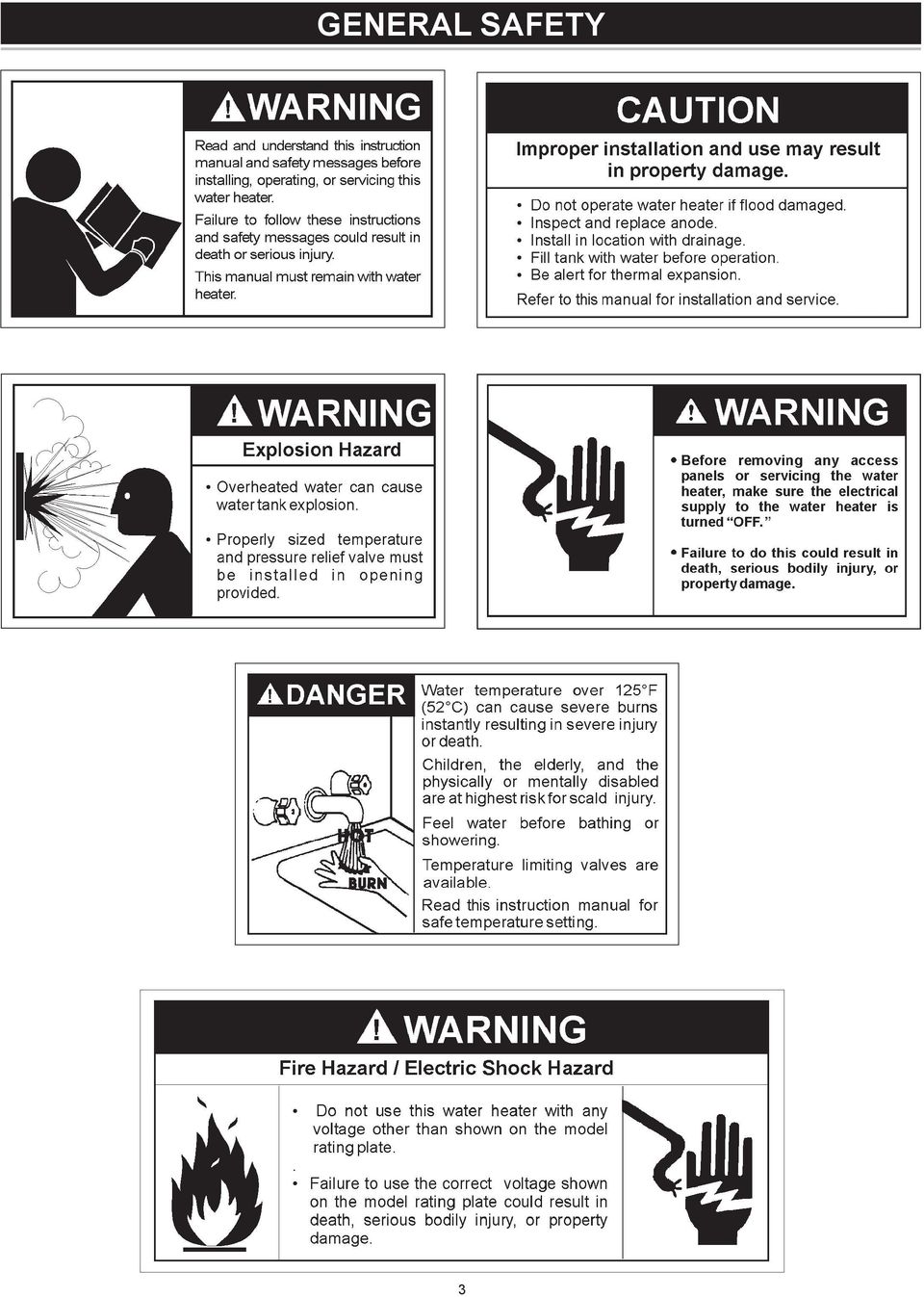
2 SAFE INSTALLATION, USE AND SERVICE Your safety and the safety of others is extremely important in the installation, use, and servicing of this water heater. Many safety-related messages and instructions have been provided in this manual and on your own water heater to warn you and others of a potential injury hazard. Read and obey all safety messages and instructions throughout this manual. It is very important that the meaning of each safety message is understood by you and others who install, use, or service this water heater. This is the safety alert symbol. It is used to alert you to potential personal injury hazards. Obey all safety messages that follow this symbol to avoid possible injury or death. DANGER WARNING CAUTION CAUTION DANGER indicates an imminently hazardous situation which, if not avoided, will result in death or injury. WARNING indicates a potentially hazardous situation which, if not avoided, could result in death or injury. CAUTION indicates a potentially hazardous situation which, if not avoided, could result in minor or moderate injury. CAUTION used without the safety alert symbol indicates a potentially hazardous situation which, if not avoided, could result in property damage. All safety messages will generally tell you about the type of hazard, what can happen if you do not follow the safety message, and how to avoid the risk of injury. The California Safe Drinking Water and Toxic Enforcement Act requires the Governor of California to publish a list of substances known to the State of California to cause cancer, birth defects, or other reproductive harm, and requires businesses to warn of potential exposure to such substances. WARNING: This product contains a chemical known to the State of California to cause cancer, birth defects, or other reproductive harm. This appliance can cause low-level exposure to some of the substances listed in the act. Hydrogen gas can be produced in a hot water system that has not been used for a long period of time (generally two weeks or more). Hydrogen gas is extremely flammable and can ignite when exposed to a spark or flame. To prevent the possibility of injury under these conditions, we recommend the hot water faucet be opened for several minutes at the kitchen sink before using any electrical appliance which is connected to the hot water system. If hydrogen is present, there will probably be an unusual sound such as air escaping through the faucet as water begins to flow. Do not smoke or have any open flame near the faucet at the time it is open. IMPORTANT DEFINITIONS Qualified Installer: A qualified installer must have ability equivalent to a licensed tradesman in the fields of plumbing and electrical installation of these appliances. This would include a thorough understanding of the requirements of the National Electrical Code and applicable local electrical and plumbing codes (and tools necessary to confirm proper installation and operation of the water heater) as they relate to the installation of electric water heaters. The qualified installer must have a thorough understanding of the water heater Instruction Manual. Service Agency: A service agency also must have ability equivalent to a licensed tradesman in the fields of plumbing and electrical installation of these appliances. This would include a thorough understanding of the requirements of the National Electrical Code and applicable local electrical and plumbing codes (and tools necessary to confirm proper installation and operation of the water heater) as they relate to the installation of electric water heaters. The service agency must have a thorough understanding of the water heater Instruction Manual. 2

3 GENERAL SAFETY 3
4 INTRODUCTION Thank You for purchasing this water heating system. Properly installed and maintained, it should give you years of trouble free service. Abbreviations Found In This Instruction Manual: ANSI - American National Standards Institute ASME - American Society of Mechanical Engineers GAMA - Gas Appliance Manufacturers Association NEC - National Electrical Code NFPA - National Fire Protection Association UL - Underwriters Laboratories Inc. SRCC - Solar Rating and Certification Corp. System description This Solar Water Heating System consists of four main parts the solar collectors, the solar pump station, the solar storage tank, and the plumbing for the heat transfer fluid. The solar pump station uses a pump to circulate a heattransfer fluid through the collector loop. This collector loop includes the solar collectors, the fluid lines or lineset and a heat exchanger. The collector loop is a closed loop, meaning there is no contact of the heat transfer fluid with your potable water or with the atmosphere. The collector loop contains only a small volume of heat-transfer fluid which is non-toxic and freeze-protected to -30 F (Freeze tolerance limits are based upon an assumed set of environmental conditions). Though freeze protection may not be necessary in all areas, the heat-transfer fluid also contains corrosion inhibitors which protect the system components, has an elevated boiling point, and is suitable throughout North America. When exposed to sunlight, the solar collectors get hot. As the heat-transfer fluid passes through the collectors, it absorbs the heat and then travels down the line-set to the tank. The hot fluid passes through the heat exchanger and heat is transferred to the potable water. After giving up its heat to the potable water, the cool heat-transfer fluid is pumped back to the solar collectors to be heated again. Hot potable water is stored in the solar storage tank. The auxiliary or back-up electric-heating guarantees hot water even under poor solar conditions (at night or when very cloudy). The minimum acceptable temperature setpoint is specified in local plumbing codes. You can save the most money on your water-heating bills by using the backup heater on your system as little as possible. If the sun shines brightly between 10 am and 3 pm, enough heat will normally be generated to keep the water hot throughout the rest of the day and night. However, on days when the sky is cloudy or when large quantities of hot water are being used, we recommend leaving the backup heater turned on and set to 120 F to provide adequate hot water. Preparing for the installation 1. Read the General Safety section of this manual first and then the entire manual carefully. If you don t follow the safety rules, the water heater will not operate properly. It could cause DEATH, SERIOUS BODILY INJURY, AND/ OR PROPERTY DAMAGE. This manual contains instructions for the installation, operation, and maintenance of the solar water heater. It also contains warnings throughout the manual that you must read and understand. All warnings and all instructions are essential to the proper operation of the water heater and your safety. READ THE ENTIRE MANUAL BEFORE ATTEMPTING TO INSTALL OR OPERATE THE WATER HEATER. 2. The installation must conform with these instructions and the local code authority having jurisdiction and the requirements of the power company. In the absence of local code requirements follow NFPA-70, the National Electrical Code (current edition), which may be ordered from: National Fire Protection Association, 1 Batterymarch Park, Quincy, MA If after reading this manual you have any questions or do not understand any portion of the instructions, call the local utility or the manufacturer whose name appears on the rating plate. 4. Carefully plan your intended placement of the water heater and collectors. INSTALLATION OR SERVICE OF THIS WATER HEATER REQUIRES ABILITY EQUIVALENT TO THAT OF A LICENSED TRADESMAN IN THE FIELD INVOLVED. PLUMBING AND ELECTRICAL WORK ARE REQUIRED. Examine the location to ensure the water heater complies with the Facts to Consider About the Location section in this manual. 5. For California installation this water heater must be braced, anchored, or strapped to avoid falling or moving during an earthquake. See instructions for correct installation procedures. Instructions may be obtained from California Office of the State Architect, 400 P Street, Sacramento, CA Massachusetts Code requires this water heater to be installed in accordance with Massachusetts 248-CMR 2.00: State Plumbing Code and 248-CMR The solar energy system described by this manual, when properly installed and maintained, meets the minimum standards established by the SRCC. This certification does not imply endorsement or warranty of this product by SRCC. 4

5 TABLE OF CONTENTS SAFE INSTALLATION, USE AND SERVICE... 2 Important Definitions... 2 GENERAL SAFETY... 3 INTRODUCTION... 4 System Description... 4 Preparing for Installation... 4 TABLE OF CONTENTS... 5 SYSTEM DIAGRAM/TYPICAL INSTALLATION... 6 SYSTEM COMPONENT PART... 7 STORAGE TANK INSTALLATION... 7 Local Codes... 7 Temperature-Pressure Relief Valve Closed System/Thermal Expansion... 8 Locating the Solar Water Heater... 8 Water Piping Installation in Residential Garages... 9 Filling the Solar Water Heater with Water... 9 Wiring of Element Thermostat Temperature Regulation Temperature Settings Temperature Adjustment Tank Sensor Draining Element Element Replacement Anode Water Heater Sounds SOLAR COLLECTOR INSTALLATION Collector Location General Considerations Collector Orientation Spanner Mounting Attaching Collector to Mounting Brackets Collector Piping Collector Piping Detail Sensor Wiring at Collector Sensor Mounting at Collector Piping Through the Roof Piping Insulation PUMP STATION INSTALLATION Pump Station Safety Instructions Safety Equipment Wall Mounting the Solar Pump Station Plumbing Configuration Function Flowmeter Start-up and Operation of the Solar Pump Station Leak Detection Flushing Filling Preparation of the Heat Transfer Fluid Filling the Solar Loop Draining PUMP STATION CONTROL INSTRUCTIONS Control Instructions System Description TROUBLESHOOTING SYSTEM MAINTENANCE REPAIR PARTS HEAT TRANSFER FLUID PROPERTIES SOLAR RATING / MODELS / WARRANTY...INSERT SHEET 5

6 SYSTEM DIAGRAM/TYPICAL INSTALLATION 6 10 INSTALL THERMAL EXPANSION TANK IF WATER HEATER IS INSTALLED IN A CLOSED WATER SYSTEM VACUUM RELIEF VALVE INSTALL PER LOCAL CODES Flow Direction 2 Discharge Pipe (DO NOT CAP OR PLUG) Metal Drain Pan Maximum Air Gap At Least 2 Greater Than The Diameter Of The Water Heater. Piped To An Adequate Drain INSTALL VACUUM RELIEF IN COLD WATER INLET LINE AS REQUIRED BY LOCAL CODES. INSTALL THERMAL EXPANSION TANK OR DEVICE IF WATER HEATER IS INSTALLED IN A CLOSED WATER SYSTEM. Figure 1. 6 INSTALL SUITABLE METAL DRAIN PANS UNDER HEATERS TO PREVENT DAMAGE DUE TO LEAKAGE. REFER TO WATER HEATER LOCATION, see LOCATING THE SOLAR WATER HEATER section.

7 Item Component Function 1 Solar collector Absorbs the sun s heat energy and transfers this to the heat transfer fluid circulating through the collector. 2 Solar storage tank Stores potable water heated by solar generated heat or installed back-up electric resistance element. 3 Double Wall Heat exchanger (inside Solar pump station) Transfers the heat from the collector loop to the potable water in the solar storage tank. 4 Solar Loop Expansion tank Allows for the expansion and contraction of the heat transfer fluid as it heat and cools. 5 Temperature and Pressure relief valve SYSTEM COMPONENT PART Required by plumbing code to automatically open and dump water if the storage tank exceeds 150 PSI of pressure or 210 F in temperature. 6 Air vent Purges air from the collector loop fluid during the installation. 7 Drain valve Used to drain the heat transfer fluid from the collector loop. 8 Mixing valve Used to temper hot water from the solar storage tank with cold inlet water to maintain appropriate temperature hot water delivered from the system. 9 Solar pump station Controls the flow of heat transfer fluid from the collectors to the tank through the heat exchanger. For a detailed description of the solar pump station see page Temperature sensor Tank and collector sensor work together to turn the circulating pump(s) on and off at preset temperature differentials. 11 Cold Water Cut-Off Valve Isolates the tank from incoming water supply. STORAGE TANK INSTALLATION Never operate the electrical heating element without being certain the solar water heater is completely filled with water. If any air is left in the top of the tank, the heating element will burn out. LOCAL CODES The installation of this solar water heater must be in accordance with these instructions and all applicable local codes and electric utility requirements. In the absence of local codes, install in accordance with the latest edition of the National Electrical Code (NFPA-70). TEMPERATURE-PRESSURE RELIEF VALVE For protection against excessive pressures and temperatures in this water heater, install temperature-pressure protective equipment required by local codes, but not less than a combination temperature-pressure relief valve certified by a nationally recognized testing laboratory that maintains periodic inspection of production of listed equipment or materials, as meeting the requirements for Relief Valves for Hot Water Supply Systems, the latest edition of ANSI Z This valve must be marked with a maximum set pressure not to exceed the marked hydrostatic working pressure of the water heater (150 lbs./sq. in.). Install the temperature-pressure relief valve directly into the fitting of the water heater. Position the valve downward and provide a discharge pipe that must terminate a maximum of six inches above a floor drain or external to the building. 7 In cold climates, it is recommended that the discharge pipe be terminated at an adequate drain inside the building. Be certain that no contact is made with any live electrical part. The discharge opening must not be blocked or reduced in size under any circumstances. Excessive length, over 15 feet, or use of more than two elbows can cause restriction and reduce the discharge capacity of the valve. No valve or other obstruction is to be placed between the temperature-pressure relief valve and the tank. Do not connect tubing directly to discharge drain unless a 6 air gap is provided. To prevent bodily injury, hazard to life or damage to property, the temperature-pressure relief valve must be allowed to discharge water in quantities should circumstances demand. If the discharge pipe is not connected to a drain or other suitable means, the water flow may cause property damage. The Discharge Pipe: Shall not be smaller in size than the outlet pipe size of the temperature-pressure relief valve, or have any reducing couplings or other restrictions. Shall not be plugged or blocked. Shall be of material listed for hot water distribution. Shall be installed so as to allow complete drainage of both the temperature-pressure relief valve, and the discharge pipe. Must terminate a maximum of six inches above a floor drain

8 or external to the building. In cold climates, it is recommended that the discharge pipe be terminated at an adequate drain inside the building. Shall not have any valve between the relief valve and tank. When installing the temperature-pressure relief valve, use two or three turns of Teflon tape or other suitable thread sealer around the threaded end of the valve. Figure 2. The temperature-pressure relief valve should be manually opened once a year. Caution should be taken to ensure that (1) no one is in front of or around the outlet of the temperature-pressure relief valve discharge line, and (2) the water manually discharged will not cause any bodily injury or property damage because the water may be extremely hot. If after manually operating the valve, it fails to completely reset and continues to release water, immediately close the cold water inlet to the water heater, follow the draining instructions, and replace the temperature-pressure relief valve with a new one. If the temperature-pressure relief valve on the appliance weeps this may be due to thermal expansion. The water supply serving this solar water heater may have a check valve installed. Contact the water supplier or local plumbing contractor on how to control this situation. Do not plug the temperature-pressure relief valve. CLOSED SYSTEM/thermal expansion As water is heated, it expands (thermal expansion). In a closed system, the volume of water will grow. As the volume of water grows, there will be a corresponding increase in water pressure due to thermal expansion. Thermal expansion can cause premature tank failure (leakage). This type of failure is not covered under the limited warranty. Thermal expansion can also cause intermittent temperaturepressure relief valve operation: water discharged from the valve due to excessive pressure build up. The temperaturepressure relief valve is not intended for the constant relief of thermal expansion. This condition is not covered under the limited warranty. A properly-sized thermal expansion tank should be installed on all closed systems to control the harmful effects of thermal expansion. Contact a plumbing service agency or your retail supplier regarding the installation of a thermal expansion tank.. LOCATING THE SOLAR WATER HEATER If you have a choice of where to install the solar water heater, these ideas may help you decide. 1. Put the solar water heater indoors as close as possible to where you use the most hot water. This water heater 8 is not intended for outdoor installation. 2. It is handy to have a floor drain, tub or sink nearby. That will make it easy to drain water from the water heater. It is also a good place to end the drain line of the temperature-pressure relief (T & P) valve. 3. The solar water heater or the pipes and the connections may, in time, leak. Put the solar water heater in a place where a water leak will not damage anything. 4. You must not put the water heater in an area where it might freeze You must turn off the electricity to the water heater before you drain it, to protect the heating elements. 5. Make sure that you are able to reach the drain valve and all access panels when the water heater is in place. This will make it easy to service the water heater. 6. The water heater must be level before you begin the piping. WATER HEATERS EVENTUALLY LEAK. The installation of the water heater must be accomplished in such a manner that if the tank or any connections should leak, the flow of water will not cause damage to the area adjoining the water heater or to lower floors of the structure. When such locations can t be avoided, a suitable metal drain pan should be installed under the water heater. Such a pan should be no greater than 1 1/2 inches deep, have a minimum length and width of at least two inches greater than the heater dimensions and must be piped to an adequate drain. This solar water heater, as all water heaters, will eventually leak. Do not install without adequate drainage provisions where water flow will cause damage. Note: normal condensation from a solar water heater may appear to be a leaking tank. WATER PIPING This solar water heater is design certified to be used with a potable water system. When connecting water piping with solder joints use only lead free solder. This solar water heater shall not be connected to any heating systems or component(s) previously used with a non-potable water heating appliance. If this solar water heater is also used for space heating applications, all piping and components connected to the solar water heater shall be suitable for use with potable water. This appliance has been design certified as a solar water heater complying with Standards for Safety - UL174 for the U.S. and can/csa-c22.2 No 110 F379.1 and F379.2

9 for Canada. The particular application of this appliance described (above paragraph) may be subject to review and approval by local code officials. Toxic chemicals such as used for treatment of boilers or nonpotable water heating appliances shall never be introduced into a potable water space heating system. d. The cold water supply line must have a shut-off valve and union. 4. Use a union to connect the hot water supply pipe to the solar water heater s hot water outlet. Operating an empty or partially filled solar water heater will result in damage to the tank. If a solar water heater is installed in a closed water system; such as one having a back flow preventer, check valve or water meter with check valve in the cold water supply line, means shall be provided to control thermal expansion. Contact the water supplier or local plumbing contractor on how to control this situation. INSTALLATION IN RESIDENTIAL GARAGES The solar water heater must be located and/or protected so it is not subject to physical damage by a moving vehicle. FILLING THE SOLAR WATER HEATER WITH WATER HOT WATER OUTLET TOP SOLAR WATER LOOP CONNECTIONS MIXING VALVE COLD WATER INLET Figure 3. The solar water heater will work better if you keep the hot water runs short. You will also get hot water faster and with less heat loss. The illustration shows the correct valves and fittings that you will need to install the solar water heater. Threaded (3/4 ) water connections are supplied through the tank top. TEMPERED WATER OTLET TEMPERATURE-PRESSURE RELIEF VALVE DRAIN LINE ACCESS COVER SIDE SOLAR WATER LOOP CONNECTIONS 6 AIR GAP Figure Buy the fittings that you need to connect the pipes. Remember that you have to connect both the hot and cold water pipes. 2. Apply a light covering of pipe joint compound to each outside thread before making connection. 3. Connect the cold water supply pipe to the cold water inlet of your solar water heater as follows: a. Look at the top cover of the solar water heater. The hot and cold connections are marked there. b. A non-metallic dip tube is supplied to carry cold water from the tank top to the bottom. Be sure that it is in the cold water inlet. c. If using copper tubing, solder tubing to an adapter BEFORE you attach the adapter to the cold water inlet. DO NOT solder the cold water supply pipe directly to the cold water inlet connection. It might harm the dip tube. DRAIN VALVE TO SUITABLE DRAIN Figure 5. Before filling the solar water heater with water, the pump station storage tank loop must be connected to the water heater. See Filling The Storage Tank Loop section of the manual. The solar water heater is equipped with top and side pump station water loop connections. Cap or plug the connections that are not used in your application. 1. Close the solar water heater drain valve. The drain valve is on the lower front of the solar water heater. 2. Open the cold water supply to the solar water heater. NOTE: THIS VALVE MUST BE LEFT OPEN WHEN THE SOLAR WATER HEATER IS IN USE. 3. Fill the solar water heater until a constant flow of water runs out an opened hot water faucet. This will let out air in the solar water heater and the piping. Close the faucet and solar loop air vent after all air has been purged and the water comes out with constant flow. You must not turn the electricity on until the solar water heater is full of water. IF ANY AIR IS LEFT IN THE TOP OF THE SOLAR WATER HEATER OR IN THE PUMP STATION STORAGE TANK LOOP THE HEATING ELEMENT WILL BURN OUT IMMEDIATELY. 4. Check all the new water piping for leaks. Fix as needed. 9

10 WIRING OF ELEMENT Determine voltage and wattage from the rating plate attached to the solar water heater. All external wiring, connection, and overcurrent protective devices must be provided and installed in accordance with the latest edition of the National Electrical Code, local codes, and local utility requirements. The solar water heater must be electrically grounded by the installer. A green ground screw has been provided on the solar water heater s junction box. The grounding electrode conductor shall be of copper, aluminum, or copper clad aluminum. The material shall be resistant to corrosion, and shall be of one continuous length without a splice or joint. Rigid metal conduit, intermediate metal conduit, or electrical metallic tubing may be used for the grounding means if conduit or tubing is terminated in fittings approved for grounding. BLACK BLACK F (49 C) F F (60 C) (66 C) RED RED ELEMENT Figure 7. THERMOSTAT Figure 6. Flexible metal conduit or flexible metallic tubing shall be permitted for grounding if all the following conditions are met: Each thermostat is factory preset at 120 F to reduce the risk of scald injury. This setting has proven by experience to be most satisfactory from the standpoint of operational costs and household needs. Solar water heaters installed in Florida require the thermostat(s) to be set at 125 F. If you wish to adjust the settings, see the Temperature Adjustment section of this installation manual on page 11. TEMPERATURE REGULATION 1. The length in any ground return path does not exceed 6 feet. 2. The circuit conductors contained therein are protected by overcurrent devices rated at 20 amperes or less. 3. The conduit or tubing is terminated in fittings approved for grounding. Never use this solar water heater unless it is completely full of water. SOLAR WATER HEATERS EQUIPPED FOR ONE TYPE VOLTAGE ONLY. This solar water heater is equipped for one type of voltage only. Check the rating plate near the bottom access panel for the correct voltage. DO NOT USE THIS SOLAR WATER HEATER WITH ANY VOLTAGE OTHER THAN THE ONE SHOWN ON THE MODEL RATING PLATE. Failure to use the correct voltage can cause problems which can result in DEATH, SERIOUS BODILY INJURY OR PROPERTY DAMAGE. If you have any questions or doubts consult your electric company. If wiring from the fuse box or circuit breaker box was aluminum for the old tank, replace it with copper wire. If you wish to reuse the existing aluminum wire, have the connection at the solar water heater made by a competent electrician. Contact your local utility to arrange for a professional electrician. HOTTER WATER CAN SCALD: Solar water heaters are intended to produce hot water. Water heated to a temperature which will satisfy clothes washing, dish washing, and other sanitizing needs can cause scalds resulting in serious personal injury and/or death. Some people are more likely to be permanently injured by hot water than others. These include the elderly, children, the infirmed, or physically handicapped. If anyone using hot water in your home fits into one of these groups or if there is a local code or state law requiring a certain temperature water at the hot water tap, then you must take special precautions. Please see Figure 8 and Table 2 for information regarding thermostat settings. In addition to using the lowest possible temperature setting that satisfies your hot water needs, some type of mixing device, such as a mixing valve should be used at the 10

11 hot water taps used by these people or at the solar water heater. Mixing valves are available at plumbing supply or hardware stores. Follow manufacturers instructions for installation of the valves. Before changing the factory setting of the thermostat, read the Temperature Adjustment section. KEEPING THE THERMOSTAT SETTING AT 120 F WILL REDUCE THE RISK OF SCALDS. Never allow small children to use a hot water tap, or to draw their own bath water. Never leave a child or handicapped person unattended in a bathtub or shower. TEMPERATURE SETTINGS NOTE: This residential solar water heater will not supply sanitizing hot water for dishwashers. The thermostat is factory set at its lowest position which approximates 120 F and is adjustable if a different water temperature is desired. For best system savings this temperature should not be changed. Read all warnings in this manual and on the solar water heater before proceeding. HIGH LIMIT CONTROL Water Temperature F Figure 8. Time for 1st Degree Burn (Less Severe Burns) (normal shower temp.) (pain threshold) 35 minutes 1 minute 5 seconds 2 seconds 1 second instantaneous RESET BUTTON ADJUSTABLE THERMOSTAT WITH HIGH LIMIT Time for Permanent Burns 2nd & 3rd Degree (Most Severe Burns) 45 minutes 5 minutes 25 seconds 5 seconds 2 seconds 1 seconds (U.S. Government Memorandum, C.P.S.C., Peter L. Armstrong, Sept. 15,1978) Table TEMPERATURE ADJUSTMENT To adjust the temperature setting: 1. Turn OFF the electrical power to the water heater, at the junction box. HAZARD OF ELECTRICAL SHOCK! Failure to turn OFF electric power to the solar water heater will result in the possibility of DEATH, SERIOUS BODILY INJURY OR PROPERTY DAMAGE. 2. Take off the access panel and fold away the insulation. 3. Turn the water temperature dial clockwise ( ) to increase the temperature, or counterclockwise ( ) to decrease the temperature. 4. Fold the insulation back in place and replace the access panel. 5. Turn ON the power supply. A non-adjustable high temperature limit control operates before steam temperatures are reached. The high limit is in the same area as the upper thermostat and must be reset manually when it activates. BECAUSE THE HIGH LIMIT ACTIVATES ONLY WHEN ABNORMALLY HIGH WATER TEMPERATURES ARE PRESENT, IT IS IMPORTANT THAT A QUALIFIED SERVICE AGENT BE CONTACTED TO DETERMINE THE REASON FOR OPERATION BEFORE RESETTING. TANK SENSOR The surface mount tank sensor should be attached to the sensor stud behind the lower door by placing the hole in the sensor over the stud provided and securing in place with a nut. The end of the tank sensor shall be connected to the red wires in the opening with wire nuts (with no regard for polarity). The other ends of the red temperature sensor extension extend from the top of the tank and shall be connected to the controller in the tank sensor position. DRAINING It is recommended that the storage tank be drained and flushed every 6 months to remove sediment which may build up during operation. The water heater should be drained if being shut down during freezing temperatures. To drain the tank, perform the following steps: 1. Turn off power to the water heater. 2. Open a nearby hot water faucet until the water is no longer hot. 3. Close the cold water inlet valve. 4. Connect a hose to the drain valve and terminate it to an adequate drain or external to the building. 5. Open the water heater drain valve and allow all of the water to drain from the tank. Flush the tank with water as needed to remove sediment. 6. Close the drain valve, refill the tank, and restart the heater as directed in this manual. If the water heater is going to be shut down for an extended period, the drain valve should be left open. IMPORTANT: Condensation may occur when refilling the tank and should not be confused with a tank leak. If the solar water heater is to be shut off and exposed to

12 freezing temperatures, it must be drained. Water, if left in the tank and allowed to freeze, will expand and damage the solar water heater. 1. Turn OFF the electrical supply to the solar water heater. Make sure the electrical supply to the solar water heater is turned OFF. Failure to heed this will result in the possibility of DEATH, SERIOUS BODILY INJURY OR PROPERTY DAMAGE. 2. Open a nearby hot water faucet until the water is no longer hot, then turn off the cold water supply and open the drain valve, leaving the hot water faucet open. 3. The drain valve must be left open during the shut-down period. Once the solar water heater is drained close the hot water faucet. ELEMENT In some water areas, scale or mineral deposits will build up on heating elements. This build up may cause a rumbling noise. Follow the element replacement directions to remove the elements from the tank. Soaking in vinegar and scraping will remove the mineral deposit. Be careful not to bend the element. ELEMENT REPLACEMENT Replacement elements must (1) be the same voltage and (2) no greater wattage than listed on the model and rating plate affixed to the solar water heater. 1. Turn OFF the electrical supply to the solar water heater. Make sure the electrical supply to the solar water heater is turned OFF. Failure to heed this will result in the possibility of DEATH, SERIOUS BODILY INJURY OR PROPERTY DAMAGE. 2. Drain the solar water heater. Follow the directions for draining. 3. Take off the access panel and take off the access panel and remove the insulation. Disconnect the wires from the heating element terminals. 4. Use an element wrench to remove the element and gasket. You should always use a new gasket when you replace the element. 5. Install new element. 6. Reconnect the wires as they were. 7. Fill the tank, following the filling directions on page 9. Fill the tank completely with water, BEFORE you turn on the electric supply. ANODE Each water heater contains at least one anode rod, which will slowly deplete (due to electrolysis) prolonging the life of the water heater by protecting the glass-lined tank from corrosion. Adverse water quality, hotter water temperatures, high hot water usage, hydronic heating devices, and water softening methods can increase the rate of anode rod depletion. Once the anode rod is depleted, the tank will start to corrode, eventually developing a leak. Certain water conditions will cause a reaction between the anode rod and the water. The most common complaint associated with the anode rod is a rotten egg smell produced from the presence of hydrogen sulfide gas dissolved in the water. IMPORTANT: Do not remove this rod permanently as it may void any warranties. A special anode rod may be available if water odor or discoloration occurs. NOTE: This rod may reduce but not eliminate water odor problems. The water supply system may require special filtration equipment from a water conditioning company to successfully eliminate all water odor problems. Artificially softened water is exceedingly corrosive because the process substitutes sodium ions for magnesium and calcium ions. The use of a water softener may decrease the life of the water heater tank. The anode rod should be inspected after a maximum of three years and annually thereafter until the condition of the anode rod dictates its replacement. NOTE: artificially softened water requires the anode rod to be inspected annually. The following are typical (but not all) signs of a depleted anode rod: The majority of the rod s diameter is less than 3/8. Significant sections of the support wire (approx. 1/3 or more of the anode rod s length) are visible. If the anode rod shows signs of either or both it should be replaced. NOTE: Whether re-installing or replacing the anode rod, check for any leaks and immediately correct if found. In replacing the anode: 1. Turn off power supply to the water heater. 2. Shut off the water supply and open a nearby hot water faucet to depressurize the water tank. 3. Drain approximately 5 gallons of water from tank. (Refer to Draining and Flushing for proper procedures). Close drain valve. 4. Remove old anode rod. Figure Use Teflon tape or approved pipe sealant on threads and install new anode rod. 6. Turn on water supply and open a nearby hot water faucet to purge air from water system. Check for any leaks and immediately correct any if found. 7. Restart the water heater as directed in this manual. See the Storage Tank Repair Parts section for anode rod location. TEFLON is a registered trademark of E.I. Du Pont De Nemours and Company. Hydrogen gas can be produced in a hot water system that has not been used for a long period of time (generally two weeks or more). Hydrogen gas is extremely flammable and explosive. To prevent the possibility of bodily injury under these conditions, open the hot water faucet for several minutes at the kitchen sink before any electrical appliances which are connected to the hot water system are used (such as a dishwasher or washing machine). If hydrogen gas is present, there will probably be an unusual sound similar to air escaping through the pipe as the hot water faucet is opened. There must be no smoking or open flame near the faucet at the time it is opened. WATER HEATER SOUNDS 1. The solar water heater is equipped with an immersion heating element for fastest recovery. If the solar water heater occasionally makes noises this is not a defect or a safety hazard. 2. Lime or scale has accumulated on the heating element causing a hissing sound. Element scale removal can be accomplished by using vinegar or by scraping. 12

13 COLLECTOR LOCATION SOLAR COLLECTOR INSTALLATION Proper location and orientation of the solar collectors is important for maximum system efficiency. The collectors should be unshaded from 10:00 am through 3:00 pm each day in every month of the year and should be located as close to the storage tank as possible to minimize heat loss in the piping runs. The best orientation is achieved when the collectors are facing due south +/- 45 and tilted at an angle from the horizontal equal to the latitude of the location A steeper angle provides better winter performance as the sun is lower in the sky. The collectors will also shed snow more effectively at the steeper angle. Figure 10 below shows many alternatives for collector mounting. Placing the collectors as close as possible to the peak of the roof will make installation easier by providing increased attic access. Figure 10. General considerations The contractor shall obtain all required permits and approvals. The installation shall conform to all federal, state and local regulations, codes, ordinances and standards governing solar water heating system installations and the contractor shall adhere to sound building safety and trade practices. Special consideration must be given to building code requirements for the penetration of structural members and fire rated assemblies. Ensure the mounting surface is solid and able to withstand in excess of 330lbs / 150kg of pull force that may be encountered during high winds. Consult a structural engineer if in doubt. The solar collector must be located in a structurally sound area of the roof that will be unshaded for the majority of the day all year round. Adjacent buildings and trees should be checked for possible winter shading. An instrument such as the Solar Pathfinder ( can be used for solar site analysis. Before the installation the contractor shall inspect the condition of the roof and notify the homeowner of any existing roof damage or necessary repairs. COLLECTOR ORIENTATION Proper tilt angle for solar collectors is latitude plus 15. This 15 additional tilt improves performance in the winter, when the sun is weaker and at a lower angle. The cost in performance in the summer when the sun is high is overcome by the hours of sunlight and strength of irradiation that occurs in the summer. Tilt mounting accessory kits are available to set the proper collector angle. Please call your local dealer for more information. When the collectors are mounted one behind the other, they should be spaced sufficiently apart so that when the sun is at its lowest altitude, the collectors will not shade each other and cause efficiency loss. See Figure 11 and Table 3. If a collector must be installed horizontally, replace the upper vent with a rubber plug in order to prevent rain penetration. See Figures 12 &

14 COLLECTOR TILT 48 A Figure 11. ROOF ANGLE & PITCH LATITUDE 25 N 30 N 35 N 40 N 45 N 50 N 55 N 60 N 65 N COLLECTOR TILT ANGLE PITCH A SPACING IN INCHES 0 FLAT / / / / / / / / /12 N/A /12 N/A /12 N/A N/A /12 N/A N/A Table 3. (For All Horizontally Mounted Collectors) Figure 12. Figure

15 CAUTION ALL PERSONS WORKING ON ROOFS SHOULD HAVE SUCCESSFULLY COMPLETED A FALL SAFETY COURSE AND SHOULD BE PROPERLY EQUIPPED WITH THE APPROPRIATE SAFETY EQUIPMENT WARNING AFTER COMPLETION OF THE COLLECTOR MOUNTING AND PRIOR TO SYSTEM CHARGING THE COLLECTORS MUST BE COVERED BY A BLANKET OR OTHER MEANS TO AVOID SOLAR RADIATION FROM HEATING THE COLLECTORS. THE SURFACES OF THE COLLECTOR CAN BECOME EXTREMELY HOT AND COULD POSE A BURN HAZARD. The most important structural consideration is to securely anchor the solar collector and the mounting hardware to the structural members of the roof with the stainless steel hardware provided. The solar collector must be attached to the mounting hardware as detailed in Figure 17. Preserving the integrity of the roof membrane is the most important roofing consideration. Ensure that all roof penetrations required to plumb and mount the solar collector are properly flashed and sealed in accordance with standard roofing practices. If the region is subject to hurricane conditions, additional steps may be required to secure the collector and mounting hardware to the structural members. In certain areas of the country, local building codes may require collector wind load testing or prescribe specific mounting procedures. Consult your local building department. Install the collectors as described in the Spanner Mounting instructions. SPANNER MOUNTING Although there are other installation methods for mounting solar collectors, it has been determined that the spanner mounting method is the most suitable for this application. Consult with your installer if other mounting means are required for your installation. 1. After locating the mounting points from Figure 14 for vertical collector mounting, Figure 15 for horizontal collector mounting, and Table 4, layout the roof as specified and drill 5/16 holes between the rafters where indicated. 2. A 12 length of stainless steel 5/16 all-thread is then inserted through the hole and a stainless steel nut, lock washer, and flat washer secures the all-thread to the mounting bracket. The all-thread should extend about 4 below the roof rafters. 3. Fabricate spanners, one for each mounting bracket, using a 2 x 4 or similar lumber. Spanners must be long enough to span at least two rafters. In the attic or crawl space drill a 5/16 hole through each spanner and insert the all-thread through it. Secure each spanner to the rafters with decking or wood screws. See Figure Fabricate spacer blocks, one for each mounting bracket, using a 2 x 4 or similar lumber the same width of the rafter next to each all-thread. Place spacer blocks next to the all-thread between the spanner and roof. Secure each spacer block to the spanners with decking or wood screws. Spacer blocks are necessary to avoid deformation of the roof. See Figure With a stainless steel nut, lock washer and fender washer secure the all-thread to each spanner. Tighten down until the mounting bracket is tightly secured to the roof (approx. 97 inch pounds). Be careful not to overtighten and dish out the roof tiles underneath the mounting bracket. Repeat steps 2-5 for the remainder of the mounting bracket locations. 15

16 DRILL POINTS (CLEARANCE HOLE for 5/16 BOLT) B C B C MOUNTING BRACKETS A RAFTER RAFTER D BASED ON 16 CENTER RAFTERS VERTICAL MOUNTING Figure 14. DRILL POINTS (CLEARANCE HOLE for 5/16 BOLT) B C B C A RAFTER D BASED ON 16 CENTER RAFTERS MOUNTING BRACKET RAFTER RAFTER HORIZONTAL MOUNTING Figure

17 NOTICE * IF MOUNTING WITH AN OPTIONAL TILT MOUNT KIT, FOR OPTIMAL COLLECTOR ANGLE REFER TO ITS INSTRUCTION SHEET FOR THE APPLICABLE A DIMENSION. COLLECTOR A B C D Vert. 3.5 X 7 86* /4 Vert. 4 X 8 97* /4 Vert. 4 X * /4 Horiz. 3.5 X * /2 Horiz. 4 X 8 47* Horiz. 4 X 10 47* Table 4. 4 MOUNTING BRACKET FLASHING STAINLESS STEEL NUT, ALL THREAD ROD LOCK WASHER, & EPDM BONDED WASHER CP COMPRESSION BRACKET WASHER SHINGLES PLYWOOD SHEETING ROOF RAFTER SPACER BLOCK ROOF RAFTER DECKING/WOOD SCREWS WOOD SPANNER (2 x 4 or 2 x 6 LUMBER) FENDER WASHER LOCK WASHER NUT Figure

18 Attaching collector to mounting brackets Once all of the mounting brackets have been secured to the roof the solar collector(s) can be installed. Refer to Figure 17 for these instructions. 1. Insert the stainless steel channel nut w/spring inside of the mounting bracket. 2. Fasten the solar collector mounting clip to the channel nut with the stainless steel bolt, lock-washer, and flat washer as shown. Do not tighten. Repeat step for the other mounting bracket locations. 3. The solar collector can now be set on the mounting brackets. To aid in handling the collectors on the roof the mounting clips may be tightened to the lower mounting brackets prior to raising the collectors. The collector can then be set on the lower mounting brackets while the top clips are fastened over the lip on the collector frame. 4. After the solar collector is in position, locate the upper mounting clip so that its lip over-hangs the lip of the solar collector frame as shown. Tighten the mounting clip to the solar collector frame securely. Repeat for the other upper mounting clips. 5. Once the upper mounting clips are secured, the bottom mounting clips can be loosened and retightened over the collector lip as directed in step Repeat steps as needed for other solar collectors. SOLAR COLLECTOR FRAME STAINLESS STEEL BOLT, LOCK WASHER, & FLAT WASHER MOUNTING CLIP STAINLESS STEEL NUT, ALL THREAD ROD with LOCK WASHER, & FLAT WASHER CHANNEL NUT with SPRING (One Piece Part) MOUNTING BRACKET ROOF Figure

19 COLLECTOR PIPING The piping of the system should be considered before a final decision is made on how the collectors are mounted. Piping should be made of copper tube of the type meeting local codes, insulated with Armacell UT Solaflex or equivalent. The maximum total piping length allowed in this system is 200 equivalent ft. Use only lead-free solder. Use of 50/50 lead solder is expressly prohibited. Use only type L or M copper tubing in the collector loop plumbing. Use of galvanized steel, CPVC, PVC, PEX or any other type of plastic pipe is prohibited. Care should be taken in the spacing of collectors as attachment of piping is easiest with properly aligned collectors. The connection between the collector panels is made with copper unions or couplings. To aid in installation the collector array layout should be planned on the ground and the unions or couplings soldered to the adjoining headers prior to lifting the collectors to the roof. Similarly the top and bottom outside header that will not be used for the inlet or outlet (should be on opposite sides) should be capped with the 1 copper cap provided while on the ground. See Figure 18. OUTLET VERTICAL MOUNT OUTLET HORIZONTAL MOUNT 1 COPPER CAPS INLET 1 COPPER CAPS INLET Figure 18. TEMPERATURE SENSOR AIR VENT 1 COPPER PIPE HEADER PIPE ADAPTER SOLAR COLLECTOR COLLECTOR (OUTLET) COLLECTOR (INLET) Figure

20 COLLECTOR PIPING DETAIL The outlets of the collector are 1 copper pipe nipples. See Figure 19. They should be piped as shown with provisions for an air vent. The air vent must be oriented vertically as this must be the highest point in the system in order for air to escape. This will prevent air lock and subsequent loss of system efficiency. Teflon tape or high temperature, high quality pipe sealant should be used when making threaded connections. The collector inlets should be piped similarly but without the air vent. SENSOR wiring AT COLLECTOR The wiring used to connect the sensors to the controller should be a minimum 18 AWG. The wiring should be twoconductor, PVC UV resistant suitable for outdoor use. Use Belden Wire No. 7409A or equivalent. SENSOR MOUNTING AT COLLECTOR The angled collector heat sensor is mounted to the outlet of the collector. See Figure 20. The stainless steel screw clamp should be used. The entire sensor should be wrapped thoroughly with insulating stretch tape such as MOCAP Silicone X-Treme Tape so that the sensor is isolated from the outside air. If possible route the sensor wire through the roof with the collector piping and connect the sensor wire to the sensor extension wire with wire nuts. PIPING THROUGH THE ROOF Preserving the integrity of the roof membrane is the most important roofing consideration. Ensure that all roof penetrations required to plumb and mount the solar collector are properly flashed and sealed in accordance with standard roofing practices. The return and supply lines should be supported under the roof to prevent undue stress on the piping assemblies at the collector. Hangers shall provide adequate support and correct pitch of pipes. Hangers or supports for insulated pipes or components shall avoid compressing or damaging the insulation material. Piping should be sloped toward drain ports with a drainage slope of no less than 2 cm vertical drop for each meter of horizontal length (1/4 inch per foot). PIPE INSULATION The collector loop piping (exterior and interior) must be well insulated with a high quality flexible EPDM closed cell insulation to minimize heat loss. The wall thickness of the pipe insulation should not be less than ¾. A 1 wall thickness is required in all areas prone to annual hard freeze conditions. When it comes to pipe insulation the rule is simple: thicker is better. The specified insulation material is Armacell UT Solaflex or equivalent. As part of the insulation requirements the final 5 ft of the cold water inlet to the storage tank must be insulated. To the extent possible, slide the insulation material over the pipe without cutting or taping. All butt joints must be sealed with high temperature contact adhesive. The use of rigid polyethylene pipe insulation is prohibited. All outdoor insulation should be protected from moisture and Ultraviolet deterioration by either paint or foil tape. Figure

INDIRECT WATER HEATER. Installation and Operating Instruction Manual
 INDIRECT WATER HEATER Installation and Operating Instruction Manual Maximum supply temperature to heat exchanger must not exceed 180 F (82 C). Safety Warning: Indirect water heaters are heat-producing
Solar Storage Tank Water Heater. Table Of Contents PAGE 2 3-8 3 4 4-5 6-8 9 10-12 10 11 12 12-13 14 15
 Solar Storage Tank Water Heater Installation Instructions and Use & Care Guide To obtain technical, warranty or service assistance during or after the installation of this water heater, call toll free
RESIDENTIAL HUD SIDE PLUMBING ELECTRIC WATER HEATERS
 Instruction Manual RESIDENTIAL HUD SIDE PLUMBING ELECTRIC WATER HEATERS FOR POTABLE WATER HEATING ONLY NOT SUITABLE FOR SPACE HEATING LISTED GAMA certification applies to all residential electric water
Residential Electric Water Heater
 Residential Electric Water Heater Installation Instructions and Use & Care Guide To obtain technical, warranty or service assistance during or after the installation of this water heater, call toll free
Installation Instructions and Use & Care Guide
 Residential Electric Water Heater Installation Instructions and Use & Care Guide To obtain technical, warranty or service assistance during or after the installation of this water heater, call toll free
Energy Smart Residential Electric Water Heater Installation Instructions
 Use & Care Guide http://waterheatertimer.org/whirlpool-energy-smart-electric.html Energy Smart Residential Electric Water Heater Installation Instructions and Use & Care Guide To obtain technical, warranty,
Your safety and the safety of others are very important.
 NATURAL GAS TO PROPANE CONVERSION KIT 090 INSTALLATION INSTRUCTIONS FOR ALTITUDES 0 -,00 FT. ONLY PROPANE CONVERSION KIT SAFETY... INSTALLATION REQUIREMENTS... Tools and Parts... LP Gas Requirements...
Use & Care Manual. Electric Tankless Water Heaters. With Installation Instructions for the Installer AP15447 (10/10)
") Use & Care Manual With Installation Instructions for the Installer Electric Tankless Water Heaters The purpose of this manual is twofold: one, to provide the installer with the basic directions and recommendations
Use & Care Manual With Installation Instructions for the Installer Electric Tankless Water Heaters The purpose of this manual is twofold: one, to provide the installer with the basic directions and recommendations
ELECTRIC WATER HEATER INSTALLATION & OPERATING INSTRUCTION MANUAL
 ELECTRIC WATER HEATER A Spanish language version of these instructions is available by contacting the manufacturer listed on the rating plate. La version espanola de estas instruccions se puede obtener
RESIDENTIAL ELECTRIC WATER HEATERS
 RESIDENTIAL ELECTRIC WATER HEATERS Everything you need to know is contained in this fully illustrated Installation Guide. For most of you, this simple procedure booklet is all that s needed. However, if
OWNER S MANUAL FORCE 10 MARINE COMPANY 23080 HAMILTON ROAD RICHMOND, BC CANADA V6V 1C9 TEL: (604) 522-0233 FAX: (604) 522-9608
 522-0233 FAX: (604) 522-9608") Electric Water Heater OWNER S MANUAL FORCE 10 MARINE COMPANY 23080 HAMILTON ROAD RICHMOND, BC CANADA V6V 1C9 TEL: (604) 522-0233 FAX: (604) 522-9608 If your water Heater is Damaged or you have questions
Electric Water Heater OWNER S MANUAL FORCE 10 MARINE COMPANY 23080 HAMILTON ROAD RICHMOND, BC CANADA V6V 1C9 TEL: (604) 522-0233 FAX: (604) 522-9608 If your water Heater is Damaged or you have questions
SHC 2.5, SHC 4 MINI-TANK ELECTRIC WATER HEATERS INSTALLATION INSTRUCTIONS FOR THE LICENSED PLUMBER SHC 2.5 SHC 4. English. English
 SHC 2.5, SHC 4 MINI-TANK ELECTRIC WATER HEATERS INSTALLATION INSTRUCTIONS FOR THE LICENSED PLUMBER The SHC series is tested and certified by WQA against NSF/ANSI 372 for lead free compliance. SHC 2.5 Table
BUILT-IN DISHWASHER INSTALLATION INSTRUCTIONS
 BUILT-IN DISHWASHER INSTALLATION INSTRUCTIONS PLEASE READ COMPLETE INSTRUCTIONS BEFORE YOU BEGIN LEAVE INSTALLATION INSTRUCTIONS AND USER'S GUIDE WITH OWNER ALL ELECTRIC WIRING AND PLUMBING MUST BE DONE
Installation Manual. Solar Pool Heating System. Read the complete manual before beginning the installation
 Solar Pool Heating System Installation Manual Read the complete manual before beginning the installation 1. Sizing the System Visit www.techno-solis.com to size the system using the sizing calculator.
Seaward Products OWNER S MANUAL WATER HEATERS. Serial Number:
 Seaward Products WATER HEATERS OWNER S MANUAL Serial Number: IMPORTANT SAFETY INSTRUCTIONS WARNING When using electrical appliances, basic safety precautions to reduce the risk of fire, electrical shock,
Air Conditioner Water Heater Model ACWH18
 Air Conditioner Water Heater Model ACWH18 Installation Guide IMPORTANT! READ THIS FIRST! Commissioning of this unit must be done by a licensed HVAC technician. Commissioning includes making the electrical
PURCHASED. IF YOU ARE UNSUCCESSFUL, PLEASE WRITE TO THE COMPANY LISTED ON THE RATING PLATE ON THE WATER HEATER.
 Instruction Manual RESIDENTIAL ELECTRIC 2.5 GALLON 120 VOLT WATER HEATER FOR POTABLE WATER HEATING ONLY NOT SUITABLE FOR SPACE HEATING LISTED ALL TECHNICAL AND WARRANTY QUESTIONS: SHOULD BE DIRECTED TO
POWER MISER 6 ELECTRIC WATER HEATER
 Owner s Manual POWER MISER 6 ELECTRIC WATER HEATER FOR POTABLE WATER HEATING ONLY. NOT SUITABLE FOR SPACE HEATING. MODEL NO. 153.326362 30 Gal. 153.326363 30 Gal. 153.326462 40 Gal. 153.326463 40 Gal.
POWER MISER TM 12 ELECTRIC WATER HEATER
 Owner s Manual POWER MISER TM 12 ELECTRIC WATER HEATER FOR POTABLE WATER HEATING ONLY. NOT SUITABLE FOR SPACE HEATING. MODEL NO. 153.321342 30 Gal. 153.321343 30 Gal. 153.321442 40 Gal. 153.321443 40 Gal.
Sun Bandit Hybrid Water Heater Installation, Operation and Solar Hybrid Energy Systems Patent(s) Pending
 Pending") Solar Hybrid Energy Systems Patent(s) Pending Sun Bandit Hybrid Water Heater Installation, Operation and Solar Hybrid Energy Systems Patent(s) Pending Maintenance Manual Solar Hybrid Energy Systems Patent(s)
Solar Hybrid Energy Systems Patent(s) Pending Sun Bandit Hybrid Water Heater Installation, Operation and Solar Hybrid Energy Systems Patent(s) Pending Maintenance Manual Solar Hybrid Energy Systems Patent(s)
USE & CARE MANUAL. Non-Metallic Electric Water Heater. Residential Electric Models 30-105 Gallon Capacity
 Non-Metallic Electric Water Heater USE & CARE MANUAL WITH INSTALLATION INSTRUCTIONS FOR THE INSTALLER Residential Electric Models 30-05 Gallon Capacity TM The purpose of this manual is twofold: one, for
INSTALLATION INSTRUCTIONS & HOME OWNERS MANUAL ECO 18 ECO 24 ECO 27 IMPORTANT SAFETY INFORMATION
 INSTALLATION INSTRUCTIONS & HOME OWNERS MANUAL ECO 18 ECO 24 ECO 27 IMPORTANT SAFETY INFORMATION As when installing or using any high voltage electrical appliance, basic safety precautions should always
CALIFORNIA PROPOSITION 65 WARNING:
 Residential Solar Water Heater USE & CARE MANUAL WITH INSTALLATION INSTRUCTIONS FOR THE CONTRACTOR LISTED 786H The purpose of this manual is twofold: one, for the installing contractor, to provide requirements
RESIDENTIAL ELECTRIC WATER HEATERS
 Instruction Manual RESIDENTIAL ELECTRIC WATER HEATERS MODELS 6-120 FOR POTABLE WATER HEATING ONLY NOT SUITABLE FOR SPACE HEATING LISTED GAMA certification applies to all residential electric water heaters
LIGHT DUTY COMMERCIAL ELECTRIC WATER HEATER INSTALLATION & OPERATING INSTRUCTION MANUAL
 LIGHT DUTY COMMERCIAL ELECTRIC WATER HEATER A Spanish language version of these instructions is available by contacting the company listed on the rating plate. La versión espãnola de estas instrucciones
Water Heaters. Use & Care Manual. Electric Point of Use IMPORTANT SAFETY INSTRUCTIONS SAVE THESE INSTRUCTIONS
 Electric Point of Use Water Heaters LISTED 786H IMPORTANT SAFETY INSTRUCTIONS Printed in USA Use & Care Manual With Installation Instructions for the Installer The purpose of this manual is twofold: one,
COMMERCIAL ELECTRIC WATER HEATER INSTALLATION & OPERATING INSTRUCTION MANUAL
 COMMERCIAL ELECTRIC WATER HEATER La A version Spanish espanola language de version estas of instrucciones these instructions se puede is available obtener al by escribirle contacting a la the fábrica company
Select Radiators Installation Guide
 Select Radiators Installation Guide Table of Contents Informational Symbols...3 Before You Begin...4 Select Rough-In... 5 Connection Installation...6 Optional Piping Arrangements...7 Conventional Wall
INSTALLATION INSTRUCTIONS & HOME OWNERS MANUAL EEMAX ELECTRIC TANKLESS WATER HEATERS IMPORTANT SAFETY INFORMATION
 INSTALLATION INSTRUCTIONS & HOME OWNERS MANUAL EEMAX ELECTRIC TANKLESS WATER HEATERS IMPORTANT SAFETY INFORMATION When installing or using any high voltage electrical appliance, basic safety precautions
Mini Tank water heater Electric undersink Water heaters GL 2.5 - GL 4 - GL 6+
 Mini Tank water heater Electric undersink Water heaters GL 2.5 - GL 4 - GL 6+ IMPORTANT SAFETY INSTRUCTIONS WARNING When using electrical appliances, safety precautions to reduce the risk of fire, electric
2010 Residential Water Heater Replacement Check List
 2010 Residential Water Heater Replacement Check List The intent of this check list is to provide installers a general reference for the enforcement of code requirements in the Greater San Diego Area. This
I N S T ALLATION INSTRUCTIONS & HOME OWNERS MANUAL IMPORTANT SAFETY INFORMATION
 I N S T ALLATION INSTRUCTIONS & HOME OWNERS MANUAL MODELS: HA018240 HA024240 HA027240 HA036240 IMPORTANT SAFETY INFORMATION As when installing or using any high voltage electrical appliance, basic safety
Sun Bandit Hybrid Water Heater Installation, Operation and Solar Hybrid Energy Systems Patent(s) Pending
 Pending") Solar Hybrid Energy Systems Patent(s) Pending Sun Bandit Hybrid Water Heater Installation, Operation and Solar Hybrid Energy Systems Patent(s) Pending Maintenance Manual Solar Hybrid Energy Systems Patent(s)
Solar Hybrid Energy Systems Patent(s) Pending Sun Bandit Hybrid Water Heater Installation, Operation and Solar Hybrid Energy Systems Patent(s) Pending Maintenance Manual Solar Hybrid Energy Systems Patent(s)
Indirect-Fired Storage Water Heater Models WH-30 through WH-80 INSTALLATION AND OPERATING INSTRUCTIONS
 Indirect-Fired Storage Water Heater Models WH-30 through WH-80 INSTALLATION AND OPERATING INSTRUCTIONS Contents Page Ratings and Specifications..................... 2 Installation Requirements......................
Installation and Operating Instruction Manual
 Electric Mini Tank Water Heaters CMT-1.3 CMT-2.5 CMT-4.0 CMT-ST70 Tempering valve Optionally available Installation and Operating Instruction Manual Table of Contents Important Safety Instructions 3 General
Mini Tank. Electric Mini Tank Water Heaters WM-1.0 WM-2.5 WM-4.0 WM-6.0. Installation and Operating Instruction Manual
 Mini Tank Electric Mini Tank Water Heaters WM-1.0 WM-2.5 WM-4.0 WM-6.0 Installation and Operating Instruction Manual Table of Contents Important Safety Instructions 3 General Information 3/6 Technical
TECHNICAL SERVICE DEPARTMENT Technical Service Bulletin 1-800-432-8373. Anode Rods, Cathodic Protection and the Porcelain (glass) Lining
 Lining") Corrosion can be defined as the destructive attack of a metal by an electrochemical reaction with its environment. Steel exposed to moisture and oxygen will rust and corrode. Corrosion is defined as the
Corrosion can be defined as the destructive attack of a metal by an electrochemical reaction with its environment. Steel exposed to moisture and oxygen will rust and corrode. Corrosion is defined as the
Section 43. Lead Paint Risk Factor NONE WATER HEATER STORAGE ELECTRIC
 WATER HEATER STORAGE ELECTRIC Lead Paint Risk Factor NONE TABLE OF CONTENTS PART 1: INSTALLATION REQUIREMENTS FOR CONVENTIONAL HOMES... 1 WATER HEATER REPAIRS... 1 1. APPLIANCE REPAIR... 1 WATER HEATER
CARING FOR YOUR WATER HEATER
 http://waterheatertimer.org/troubleshoot-rheem-tankless-water-heater.html Water Heater Inspections CARING FOR YOUR WATER HEATER Venting System (Direct Vent Only) The venting system should be inspected
Electric Mini Tank Water Heaters WM-2.5 & WM-4.0
 Electric Mini Tank Water Heaters WM-2.5 & WM-4.0 Installation and Operating Instruction Manual Table of Contents Important Safety Instructions 2 Technical Data 3-4 General Information 5 Technical Description
Techtanium Solar Indirect Water Heater Instruction Manual
 To the Installer: Please attach these instructions next to the water heater. To the Consumer: Please read these and all component instructions and keep for future reference. Techtanium Solar Indirect Water
Installation and Troubleshooting Instructions for Electric Tankless Residential Water Heaters.
 Model Number: Serial Number: Information Manual Installation and Troubleshooting Instructions for Electric Tankless Residential Water Heaters. ATTENTION: IF YOU ARE NOT A LICENSED PLUMBER OR A LICENSED
Electric Mini Tank Water heaters GL 2.5 - GL 4 - GL 6+
 Electric Mini Tank Water heaters GL 2.5 - GL 4 - GL 6+ IMPORTANT SAFETY INSTRUCTIONS WARNING When using electrical appliances, safety precautions to reduce the risk of fire, electric shock or injury to
Solar Skies Stainless Tank Series Water Heater
 Solar Skies Stainless Tank Series Water Heater Installation Operation Maintenance Solar Skies Stainless Tank CD1051A.doc Last Revision: 1/31/2011 1 CONTENTS Part 1 Product and Safety Information.....................................
Plumbing. Helpful Hints Residential Construction. Lincoln County. Bert Polk Plumbing Inspector
 Plumbing Helpful Hints Residential Construction Bert Polk Plumbing Inspector Lincoln County 2015 Waste and vent fittings Vent 90 medium 90 long 90 1/16 bend,1/8 bend,1/6 bend, medium 90 san tee combination
PARTS CATALOG RPPCR01111_Front_Backcx.indd 1 RPPCR01111_Front_Backcx.indd 1 11/21/11 1:41 PM 11/21/11 1:41 PM
 PARTS CATALOG RPPCR01111_Front_Backcx.indd 1 11/21/11 1:41 PM RELIANCE Has Everything Your Customers Need to Do the Job Right! Reliance Water Heater Company was founded in 1981 to provide a water heater
SunMor SM-V30 Solar Water Heater Installation Manual
 SunMor SM-V30 Solar Water Heater Installation Manual Rev. 1.02 Congratulations on the purchase of your new SunMor SM-V30 from Nature s Comfort LLC! You must read this entire instruction manual before beginning
Use & Care Manual. Electric Residential Water Heaters. With Installation Instructions for the Installer. with Electronic Control AP16697-1 (10/13)
") Use & Care Manual With Installation Instructions for the Installer Electric Residential Water Heaters with Electronic Control The purpose of this manual is twofold: one, to provide the installer with the
Use & Care Manual With Installation Instructions for the Installer Electric Residential Water Heaters with Electronic Control The purpose of this manual is twofold: one, to provide the installer with the
RESIDENTIAL ELECTRIC WATER HEATER OWNER S MANUAL INSTALLATION AND OPERATING INSTRUCTIONS
 RESIDENTIAL ELECTRIC WATER HEATER OWNER S MANUAL INSTALLATION AND OPERATING INSTRUCTIONS DANGER If the information in these instructions is not followed exactly, a fire or explosion may result causing
Watts Pure Water Systems
 Watts Pure Water Systems WM-120-PT Installation and Operation Manual Premier Water Systems Do not use with water that is microbiologically unsafe or of unknown quality without adequate disinfection before
Instruction Manual. A DIVISION OF A. O. SMITH CORPORATION RENTON, WASHINGTON www.hotwater.com
 Instruction Manual Commercial Semi-Instantaneous Water Heaters ALL HWI MODELS INSTALLATION - OPERATION - SERVICE - MAINTENANCE - LIMITED WARRANTY A DIVISION OF A. O. SMITH CORPORATION RENTON, WASHINGTON
Pre-Fab Easy Installation For Models: 006-CT-USK, 008-CT-USK Installation and Operating Instructions for Existing Homes with Standard Piping
 Instruction Sheet 102-140 Pre-Fab Easy Installation For Models: 006-CT-USK, 008-CT-USK Installation and Operating Instructions for Existing Homes with Standard Piping Plant I.D. 001-1024 EFFECTIVE: November
PURCHASED. IF YOU ARE UNSUCCESSFUL, PLEASE WRITE TO THE COMPANY LISTED ON THE RATING PLATE ON THE WATER HEATER.
 Instruction Manual RESIDENTIAL ELECTRIC 2.5 GALLON 120 VOLT WATER HEATER FOR POTABLE WATER HEATING ONLY NOT SUITABLE FOR SPACE HEATING LISTED ALL TECHNICAL AND WARRANTY QUESTIONS: SHOULD BE DIRECTED TO
RESIDENTIAL ELECTRIC WATER HEATERS
 Instruction Manual RESIDENTIAL ELECTRIC WATER HEATERS FOR POTABLE WATER HEATING ONLY NOT SUITABLE FOR SPACE HEATING LISTED GAMA certification applies to all residential electric water heaters with capacities
Making Your Home Ready For Solar Water Heating
 Making Your Home Ready For Solar Water Heating During construction or a major renovation, making a home ready to use solar energy can be easy and inexpensive. When the time comes to install your solar
Instruction Manual. place these instructions adjacent to heater and notify owner to keep for future reference.
 Instruction Manual COMMERCIAL ELECTRIC WATER HEATERS A DIVISION OF A.O. SMITH CORPORATION RENTON, WASHINGTON MODELS DVE-150 THRU DVE-10000 DHE-200 THRU DHE 10000 INSTALLATION - OPERATION - SERVICE - MAINTENANCE
Electric Water Heater
 Electric Water Heater Operation and Installation Manual (LIMITED WARRANTY AND TANK REPLACEMENT POLICY) The following information should be noted at time of installation and retained for future reference.
AMERICAN SOLAR WATER HEATING SYSTEM The Best Water Heating Solution Under The Sun
 AMERICAN SOLAR WATER HEATING SYSTEM The Best Water Heating Solution Under The Sun American Solar Water Heating Systems The American solar thermal system is more than just a solar water heater - it s the
Guidelines for Earthquake Bracing of Residential Water Heaters
 Guidelines for Earthquake Bracing of Residential Water Heaters Department of General Services Division of the State Architect 1102 Q Street, Suite 5100 Sacramento, CA 95814 Phone: (916) 324-7099 Fax: (916)
USE &CARE GUIDE. Remote Faucet Pump System. See Important Safeguards on page 2
 Remote Faucet Pump System USE &CARE GUIDE See Important Safeguards on page 2 An exclamation point within an equilateral triangle is intended to alert user to the presence of important operating and maintenance
INSTALLATION & MAINTENANCE MANUAL TURBOPOWER GAS, OIL & GAS/OIL WATER HEATER
 INSTALLATION & MAINTENANCE MANUAL TURBOPOWER GAS, OIL & GAS/OIL WATER HEATER Installation and service must be performed by a qualified service installer, service agency or the gas supplier. Oil Gas/Oil
INDIRECT WATER HEATER
 INDIRECT WATER HEATER INSTALLATION AND OPERATING INSTRUCTIONS Read and understand these instructions thoroughly before starting TABLE OF CONTENTS I) Introduction............................2 II) Safety.................................2
Water Heaters. Use & Care Manual. Electric Residential. With Installation Instructions for the Installer
 Electric Residential Water Heaters Use & Care Manual With Installation Instructions for the Installer Single and Double Element Models, Residential 0 0 Gallon The purpose of this manual is twofold: one,
Hot, Warm and Cold Mineral Water Cooler [Models Cool18, Cool25, Cool36, Cool50, Cool75, Cool100]
![Hot, Warm and Cold Mineral Water Cooler [Models Cool18, Cool25, Cool36, Cool50, Cool75, Cool100]](/thumbs/26/7741864.jpg "Hot, Warm and Cold Mineral Water Cooler [Models Cool18, Cool25, Cool36, Cool50, Cool75, Cool100]") Hot, Warm and Cold Mineral Water Cooler [Models Cool18, Cool25, Cool36, Cool50, Cool75, Cool100] PLEASE READ BEFORE INSTALLATION TO PREVENT DAMAGE TO THE COOLER HOT WATER TANK STEAM EXAUST VENT (CAUTION!)
Hot, Warm and Cold Mineral Water Cooler [Models Cool18, Cool25, Cool36, Cool50, Cool75, Cool100] PLEASE READ BEFORE INSTALLATION TO PREVENT DAMAGE TO THE COOLER HOT WATER TANK STEAM EXAUST VENT (CAUTION!)
Installation Manual DIAPHRAGM WELL TANK
 Installation Manual DIAPHRAGM WELL TANK IN-LINE SERIES: 2-5 & 7 GALLON VERTICAL SERIES: 14-20-25-32-36-52-65-86-96-119 GALLON HORIZONTAL SERIES: 7-14 & 20 GALLON NO LEAD NO LEAD: The weighted average of
ASX7-4-IOM-7 J30-08579
 INSTALLATION INSTRUCTIONS 4" COMBUSTION AIR INLET KIT TUBULAR GAS FIRED DIRECT SPARK PROPELLER UNIT HEATERS UNIT CONVERSION & CATEGORY III VENTING FOR SEPARATED COMBUSTION For 30,000 to 75,000 BTU/HR SUPPLEMENT
Guidelines for Earthquake Bracing Residential Water Heaters
 Guidelines for Earthquake Bracing Residential Water Heaters Department of General Services Division of the State Architect In accordance with the Health and Safety Code Section 19215, the Division of the
INSTRUCTIONS FOR USE, MAINTENANCE AND INSTALLATION OF THE
 SUN & HEAT SOLAR PRODUCTS INSTRUCTIONS FOR USE, MAINTENANCE AND INSTALLATION OF THE SOLAR DOMESTIC WATER HEATER THERMOSIPHON 150/2.5 (TYPICAL INSTRUCTIONS FOR A CLOSED LOOP THERMOSIPHONIC SYSTEM ON A FLAT
AMX300 DirectConnect Mixing Valve Kits
 AMX300 DirectConnect Mixing Valve Kits INSTALLATION INSTRUCTIONS Tools needed (not supplied) 1. Wrench 2. Pliers Safety Definitions These safety terms identify information you must read. CAUTION Indicates
TABLE 1. Rugged cast aluminum alloy casing,celcon waterways with nichrome parts White (unless stainless steel housing)
") CHRONOMITE INSTANT-FLOW MICRO WATER HEATER INSTALLATION AND OPERATION INSTRUCTIONS - (LOW FLOW MODELS) (Before installation, compare electrical needed for the model of heater selected) TABLE 1 Model No.
CHRONOMITE INSTANT-FLOW MICRO WATER HEATER INSTALLATION AND OPERATION INSTRUCTIONS - (LOW FLOW MODELS) (Before installation, compare electrical needed for the model of heater selected) TABLE 1 Model No.
Cooling system components, removing and installing
 Engine BHW Cooling system components, removing and installing Page 1 / 24 19-1 Cooling system components, removing and installing Warning! When doing any repair work, especially in the engine compartment,
Electric Mini Tank Water Heaters
 Electric Mini Tank Water Heaters EMT1 - EMT2.5 - EMT4 - EMT6 Installation and Operating Instruction Manual Table of Contents Important Safety Instructions 2 Technical Data 3-4 General Information 5 Technical
Use & Care Manual. Electric Water Heaters. With Installation Instructions for the Installer. Single and Double Element Models, 15 105 Gallon
 Use & Care Manual With Installation Instructions for the Installer Electric Water Heaters Single and Double Element Models, 15 105 Gallon The purpose of this manual is twofold: one, to provide the installer
USE & CARE MANUAL. Residential Solar Water Heater with Heat Exchanger WITH INSTALLATION INSTRUCTIONS FOR THE CONTRACTOR
 Residential Solar Water Heater with Heat Exchanger USE & CARE MANUAL WITH INSTALLATION INSTRUCTIONS FOR THE CONTRACTOR LISTED Solar Water Heater 96G1 The purpose of this manual is twofold: one, for the
Installation Instructions
 Installation Instructions Built-In Dishwasher If you have questions, call 1-800-4-MY-HOME (1-800-469-4663) or visit our website at: www.sears.com BEFORE YOU BEGIN Read these instructions completely and
with MERCURY FREE 1 HP Relays ! WARNING Before using this product read and understand instructions.
 B Installation & Maintenance Instructions MM-414 Series 150E and 157E Low Water Cut-Off/Pump Controllers For Steam Boilers and Other Level Control Applications A Typical Applications: Primary or secondary
Instruction Manual for Residential Manufactured Home Gas Water Heaters
 Instruction Manual for Residential Manufactured Home Gas Water Heaters FOR USE ONLY IN MANUFACTURED HOMES GAMA certification applies to all residential gas water heaters with capacities of 20 to 100 gallons
INSTALLATION INSTRUCTIONS Fan Coil Replacement Coil Kit EBX & EBXX
 Fan Coil Replacement Coil Kit EBX & EBXX These instructions must be read and understood completely before attempting installation. These instructions covers the installation of replacement coil kit into
3. SEISCO PARTS & SERVICE REMOVAL AND REPAIR GUIDE
 4 3. SEISCO PARTS & SERVICE REMOVAL AND REPAIR GUIDE A. Changing the Control Board B. Replacing a Heating Element C. Thermistor Replacement D. High Limit Switch Replacement E. Level Detector Replacement
Policy on Water Heater Installations Policy No. UPC 510-1-94 Effective: September 1, 1995 Revised: February 10, 1996
 CITY OF SAN JOSE BUILDING DIVISION POLICY Policy on Water Heater Installations Policy No. UPC 510-1-94 Effective: September 1, 1995 Revised: February 10, 1996 All new and replacement water heaters installed
Installation Manual DIAPHRAGM WELL TANK
 Installation Manual DIAPHRAGM WELL TANK Safety Instructions Installation Warranty IN-LINE SERIES: 2-5 & 7 GALLON HORIZONTAL SERIES: 7-14 & 20 GALLON VERTICAL SERIES: 14-20-32-36-52-86-96-119 GALLON KEEP
Duda Solar Water Heating Systems
 Duda Solar Water Heating Systems Operation and Maintenance Manual Duda Energy LLC 1112 Brooks St SE Decatur, AL 35601 Phone Contact: 256-340-4866 www.dudaenergy.com 1 Table of Contents General Information...
NAVIEN AMERICA INC. 17855 FITCH AVENUE
 Navien America Inc. Specification Details for the Navien models: CC-240 CC-240A For Potable Water Heating and Space Heating NAVIEN AMERICA INC. 17855 FITCH AVENUE IRVINE, CALIFORNIA, USA 92614 Toll Free:
Oil and Coolant Circulating Heating System. Model - OCSM
 Oil and Coolant Circulating Heating System Model - OCSM Installation & Operation Manual 216280-000 REV 2 Identifying Your System The HOTSTART heating system is designed to heat fluids for use in marine
ELECTRIC RESIDENTIAL ELECTRIC WATER HEATER OWNER'S MANUAL GENERAL SAFETY INFORMATION TABLE OF CONTENTS EXTERNAL DAMAGE INSULATION BLANKETS
 RESIDENTIAL ELECTRIC WATER HEATER OWNER'S MANUAL Thank you for buying this water heater from A.O. Smith Water Products Company. We appreciate your confidence in our products. Please read through this informative
I N S T A L L A T I O N I N S T R U C T I O N S F O R T H E H i l k o i l Energy S aving Hot Water Kit
 I N S T A L L A T I O N I N S T R U C T I O N S F O R T H E H i l k o i l Energy S aving Hot Water Kit IMPORTANT: These installation instructions are meant to be used as a guide for woodstove owners and
PURCHASED. IF YOU ARE UNSUCCESSFUL, PLEASE WRITE TO THE COMPANY LISTED ON THE RATING PLATE ON THE WATER HEATER.
 Instruction Manual RESIDENTIAL GAS WATER HEATERS FOR USE ONLY IN MANUFACTURED HOMES GAMA certification applies to all residential gas water heaters with capacities of 20 to 100 gallons with input rating
Use & Care Manual. Electric Residential Water Heaters. With Installation Instructions for the Installer
 Use & Care Manual With Installation Instructions for the Installer Electric Residential Water Heaters Single and Double Element Models, Residential 0 0 Gallon The purpose of this manual is twofold: one,
THERMOSTATIC MIXING VALVE TRIM K-T9493, K-T9494
 THERMOSTATIC MIXING VALVE TRIM K-T9493, K-T9494 1. BEFORE YOU BEGIN IMPORTANT INSTRUCTIONS READ AND SAVE FOR THE CONSUMER WARNING: Risk of scalding or other severe injury. Before completing installation,
Geyser-R Heat pump water heater Installation manual
 Geyser-R Heat pump water heater Installation manual 1 Version 2.9 SAFETY INFORMATION Please read carefully to prevent serious accidents or injury. The Geyser-R Heat Pump Water Heater must be installed
Tankless Water Heater
 Tankless Water Heater USER S INFORMATION MANUAL Models WGRTNG199 / WGRTLP199 WGRTCNG199 / WGRTCLP199 NOTICE: Westinghouse reserves the right to make product changes or updates without notice and will not
Arapahoe County Residential Water Heater Installation and Inspection Guide
 Arapahoe County Residential Water Heater Installation and Inspection Guide The attached handout is designed to be a general permit submittal and inspection guide covering most installation instances, however
Ducoterra Radiant Heating Panel Installation Manual
 Ducoterra Radiant Heating Panel Installation Manual 1. Introduction Your new radiant heating panels are designed to heat living and working spaces rapidly and efficiently by radiant heating. Like the sun,
INSTANT HOT WATER RECIRCULATING SYSTEM
 INSTANT HOT WATER RECIRCULATING SYSTEM INSTALLATION AND OPERATING INSTRUCTIONS Save manual for future reference MODEL 500800 Warning Please read carefully before proceeding with installation. Your failure
How To Install An Evaporator Coil
 EVAPORATOR COIL INSTALLATION INSTRUCTIONS EVAPORATOR COIL SAFETY... INSTALLATION REQUIREMENTS... Tools and Parts... System Requirements... Location Requirements... Drain Requirements... INSTALLATION INSTRUCTIONS...
foot skylight) is enough to knock a worker off their feet. A 10 mph wind gust on a 5 x 6 skylight develops a wind force of 270 lbs.
 is enough to knock a worker off their feet. A 10 mph wind gust on a 5 x 6 skylight develops a wind force of 270 lbs.") Skylight Installation Instructions This document provides instruction and guidelines for installation of both curb mount (CM) and self flashing (SF) unit skylights on flat, pitched (> or equal to 3/12
Skylight Installation Instructions This document provides instruction and guidelines for installation of both curb mount (CM) and self flashing (SF) unit skylights on flat, pitched (> or equal to 3/12
SERVICE MANUAL RESIDENTIAL ELECTRIC AND LIGHT DUTY COMMERCIAL ELECTRIC WATER HEATERS. Troubleshooting Guide and Instructions for Service
 RESIDENTIAL ELECTRIC AND LIGHT DUTY COMMERCIAL ELECTRIC WATER HEATERS SERVICE MANUAL Troubleshooting Guide and Instructions for Service (To be performed ONLY by qualified service providers) Models Covered
VOYAGER 570G. 744A Sprayer Control
 VOYAGER 570G 744A Sprayer Control U S E R M A N U A L U S E R M A N U A L Table of Contents CHAPTER 1 - INTRODUCTION...1 SYSTEM CONFIGURATIONS...1 KIT CONTENTS...3 CONTROL HOUSING ASSEMBLY...5 CHAPTER
Speedflow Undersink Unvented Water Heater. Models SF10K and SF15K. Instruction Manual
 Speedflow Undersink Unvented Water Heater Models SF10K and SF15K Instruction Manual Version 2.0 May 2009 Hyco SpeedFLOW UnVENTED WATER HEATER Models SF10K (10 Litres) and SF15K (15 Litres) 1. Introduction
WINTERIZING YOUR HOME PLUMBING AT BLUE RIDGE SHORES
 WINTERIZING YOUR HOME PLUMBING AT BLUE RIDGE SHORES The following are suggestions to help you winterize your home plumbing. They are for homes where the heat is not left on during the winter months. There