Remediation of Oilfield Brine-impacted Soil Using a Subsurface Drainage System and Hay
|
|
|
- Curtis Lynch
- 8 years ago
- Views:
Transcription
1 Remediation of Oilfield Brine-impacted Soil Using a Subsurface Drainage System and Hay Running head: Harris, et al. : BRINE IMPACT REMEDIATION Thomas M. Harris*, J. Bryan Tapp and K.L. Sublette *University of Tulsa, Department of Chemistry and Biochemistry, Tulsa, OK University of Tulsa, Department of Geosciences, Tulsa, OK University of Tulsa, Center for Applied Biogeosciences, Tulsa, OK Corresponding author, K.L. Sublette (918) ; kerry-sublette@utulsa.edu ACKNOWLEDGEMENTS A number of students from the Departments of Chemistry and Biochemistry, Chemical Engineering and Geosciences at the University of Tulsa have been involved in the collection and analysis of samples. Special recognition should be given to Rick Yates, Christina Dewan and Kimberly (Sullivent) Schulte. Dorathy Perumallapali, Andrea High and Jason McConnell also contributed much time and effort to these projects. Adam Ryburn of the Botany Department, Oklahoma State University, provided some identifications. Funding for installation of the SDS was provided by the National Petroleum Technology Office of the U.S. Department of Energy, through BDM Petroleum Technologies. The authors would also like to thank Bob Hamilton of the Tallgrass Prairie Preserve for providing access to the research sites (and numerous bales of hay). ABSTRACT This study involved a demonstration of a novel remediation technology for brineimpacted soil at a site in Osage County, OK, which was recently contaminated with produced 1

2 water brine from a leak in a steel line leading to a saltwater disposal well. At this site topsoil was underlain by clay-rich subsoil which had resulted in leaching and transport of brine components from the site to an environmental receptor (farm pond) downgradient. Encouraging further movement of brine components using natural drainage patterns would have only further contaminated the pond. A subsurface drainage system (SDS) was installed to intercept brine components, enhance the lateral subsurface transport (LST) process, and prevent further contamination of the pond. Chloride and sodium concentrations in the soil were reduced by an average of 93 and 78%, respectively, in the 4 years after the SDS was installed. More importantly, approximately 95% of the site revegetated during this time period. This is in stark contrast to the complete lack of vegetation before the current work was initiated. A thick layer of prairie hay was applied across the surface of this site after the SDS was installed. In addition to limiting the rate of evaporation from the site this organic material appears to have also played a significant role in desalination and revegetation of the site. The fibrous hay enhanced leaching after mechanical disruption of the soil and provided soil organic matter that helped to build soil structure and sustain the soil ecosystem. Based on the results from this study, a two-step remediation strategy for brine-impacted topsoil, is proposed. The first step involves the tilling of hay and fertilizer into the soil, while the second step involves a subsurface drainage system, if necessary. Key Words: Produced brine, impacted soil, cost-effective remediation, gypsum, subsurface drainage system INTRODUCTION During the production of petroleum, saline produced water is also brought to the surface. At one time it was common practice for this fluid to be discharged at the surface. Today, oilfield brine is usually re-injected into a deep geological formation, often the one from which it was withdrawn. Nevertheless, brine spills at the wellhead or tank battery are a frequent occurrence. An oilfield brine spill will convert the soil to a saline condition (Harris, 1998). This causes established plants to perish because a high concentration of ions in the soil solution 2
 was installed to intercept brine components, enhance the lateral subsurface transport (LST) process, and prevent further contamination of the pond.")
3 makes it difficult for plant roots to absorb water by osmosis. Contamination with oilfield brine may also produce a sodic soil. Sodic soils exhibit poor structure, characterized by a low hydraulic conductivity, because the aggregation of clay particles is inhibited when sodium ions displace other ions (notably calcium ion) from cation exchange sites. Dispersed clay particles are free to migrate in the soil water until they become lodged in, and plug off, the smaller pores in the soil. Soil that is unable to support plant life, as result of either salinity or sodicity, will eventually succumb to erosion. The resultant "salt scar" is very costly to remediate. Therefore, it is an economic imperative that brine-impacted soil be remediated as soon as possible after the spill has occurred. On the other hand, since oilfield brine does not represent a threat to human health unless it impacts drinking water, and the contaminated land may not be that valuable (from an economic perspective), the means by which the brine components are removed from the soil must be relatively inexpensive. In 1997, the American Petroleum Institute (API) published a field manual concerning the remediation of brine-impacted soil (Carty et al., 1997). This manual describes three separate remedial activities. The first, excavation of the contaminated soil (with appropriate disposal elsewhere), is utilized when the brine components represent a significant threat to nearby surface water (or groundwater). However, this approach should be used as a last resort because it is very expensive. The second activity involves the addition of amendments (e.g. gypsum) to improve the structure of the topsoil and encourage the downward movement of brine components through the soil profile (driven by rainfall or surface irrigation). The success of this approach is critically dependent on the characteristics of the subsoil (or underlying geologic materials); if the hydraulic conductivity of these materials is low, the brine components will remain concentrated in the topsoil. The third activity utilizes halophytes, plants capable of surviving in highly saline soil, to stabilize the topsoil. Unfortunately, the knowledge base required to match known halophytes to local climatological and ecological conditions is not yet available. 3

4 The purpose of this research project was to demonstrate a cost-effective remediation strategy specifically for oilfield brine-impacted sites at which the downward movement of the contaminants through the soil profile is inhibited and lateral movement of brine components threatens an environmental receptor. In this study a recent brine spill site in Osage County, OK (referenced here as Site B) was remediated. The site is located in the Tallgrass Prairie Preserve (TGPP), which is owned and operated by The Nature Conservancy, a non-profit organization dedicated to the preservation of native habitats. The mineral rights to this area belong to the Osage Nation. On the site a subsurface drainage system (SDS) was utilized. Commonly used for the draining of waterlogged cropland (Jeffords, 1976), SDS s have been applied to a limited number of oilfield brine impacted sites (Weathers et al., 1994; Sewell et al, 2000). Lateral subsurface transport is enhanced by an SDS. EXPERIMENTAL METHODOLOGY AND SITE INFORMATION Site B is located at NE Sec. 12 T27N R8E. The soil survey for Osage Co., Oklahoma (United States Soil Conservation Service, 1979) provides some information on the characteristics of the soil at this site. The dark brown topsoil is classified as silt loam, while the tan-colored subsoil is silty clay. Site B is mapped as the Steedman-Coweta complex, with a slope between 3 and 15%. The Steedman soil exhibits a topsoil depth of approximately 8 inches (20 cm), medium water capacity, slow water permeability and a seasonal water table 6-12 inches (15-30 cm) below the surface. The subsoil exhibits a gray color at greater depth, indicative of weathered or diagenetically altered shale. Shale was not encountered in a 2-m deep excavation at the northwest corner of the site; thus, the lowest subsoil layer for the Steedman can be quite thick. The Coweta soil is typically thinner than the Steedman, has a lower water capacity, and is derived from sandstone. There is a sandstone outcrop just above the contaminated area on this site, suggesting that Coweta soil is present at the top of the site. In the late winter of 1995, a 2-in (5-cm) steel pipe connecting a tank battery to the produced water re-injection well failed in two places due to corrosion, resulting in the loss of approximately 400 bbl (64 m 3 ) of brine. The brine flowed 60 meters downhill to a shallow ditch, 4
, which is owned and operated by The Nature Conservancy, a non-profit organization dedicated to the preservation of native habitats.")
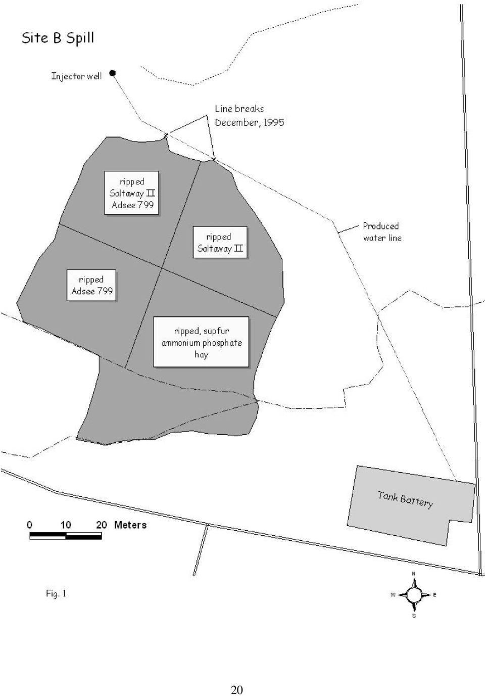
5 then rainfall conveyed brine components to a stock pond approximately 500 m downgradient. Migration of brine components over the next two years (by overland transport and lateral subsurface transport) resulted in approximately 2 acres (0.8 hectares) of contaminated soil and a continual source of contamination for the pond. Site B was treated for the first time approximately two months after the spill. The choice of remedial treatment(s) was made by the operator of the lease in consultation with Tallgrass Prairie Preserve officials but not the authors. The contaminated area was first ripped with a bulldozer and then divided into four quadrants, with each quadrant receiving a different amendment applied to the surface (Fig. 1). Details of these early remedial treatments are provided in Table 1. Three growing seasons after this initial remediation, the site was still almost completely bare. Consequently, in December 1997, a subsurface drainage system (SDS) was installed. This system featured four lateral lines of 4-in (10-cm) slotted polyethylene drainage pipe buried approximately 1 m beneath the surface, just below the topsoil-subsoil interface. The pipe was surrounded by approximately 3 inches (7 cm) of limestone gravel with an average particle diameter of 1/2 inch (1.3 cm). The dirt from the ditches was used to construct berms immediately downgradient of the drainage lines, as well as a dam across the shallow ditch noted above to encourage infiltration of rainfall. Site B and the SDS are illustrated schematically in Fig. 2. It can be seen that the four drainage laterals effectively divided the site into four sections. The upper three drainage lines were connected to a collection line, constructed of unslotted pipe that traversed the north side of the contaminated area. This line and the lowest lateral line were connected to a sump buried in the lowest corner of the site. Initially, a 1000 L open-top polyethylene tank served as the sump. In February, 1998 this was replaced with a 25- bbl (4-m 3 ) steel tank. A gasoline-powered pump and connecting line were used to transfer the contents of the SDS sump to the lease s produced water disposal system (saltwater holding tank). A cumulative flow meter in the connecting line was used to record this transfer, which occurred 5
 was made by the operator of the lease in consultation with Tallgrass Prairie Preserve officials but not the authors.")
6 each day that the pumper was able to include this activity in his schedule. A sample of the fluid being transferred was collected manually by the pumper on a weekly basis. Soon after installation of the SDS most of the site was disked. Twenty large round bales of hay were then unrolled, providing a 4-inch (10-cm) thick layer over most of the site. Subsections L1S1 and L1S2, as well as the entire L4 section, were too wet to allow disking or the application of hay at that time. Permanent sampling stations designated by steel pins were established on the site at this time (see Fig. 2). Subsections L1S1 and L1S2, being closest to the origin of the spill, initially exhibited the highest levels of contamination initially (see below). When revegetation did not occur in this area during the first growing season following installation of the SDS and hay treatment, further remedial activities were undertaken. Subsection L1S1 was treated with gypsum following API guidelines (Carty et al., 1997) and then tilled, while subsection L1S2 was covered with a 4-in (10-cm) thick layer of prairie hay and then tilled. Site B is within 2 miles (3.2 km) of the Foraker weather monitoring station of the Oklahoma Mesonet (Oklahoma Climatological Survey). Thus, rainfall amounts for the time period addressed in this paper are known to a high degree of accuracy. Sample Collection and Analysis Routine sampling of the site involved the collection of surface soil only. Using a shovel, soil to a depth of 10 cm was collected from four locations chosen randomly from within a circle with a radius of 1 m centered on the rebar pin designating the sampling station. The soil was placed on a clean sheet of plastic and composited thoroughly before a representative sub-sample was transferred, using a clean trowel, to a polyethylene bag with Ziploc closure. Since one objective of this study was to monitor the salt concentration in the soil over time, the 1:1 extract was employed instead of the saturated paste extract (Harris et al., 1998). The 1:1 extract was prepared by combining a mass of high purity water (HPW) produced with a Milli-Q system (Millipore) equal to that of a soil sample (approximately 100 g) dried overnight in an oven at 110 C. After allowing the soil and water to equilibrate overnight in a sealed 6
.")
7 container, the extract was recovered by vacuum filtration through qualitative filter paper (Millipore). The soil extracts, leachate samples from the SDS, and a sample of produced water from the site were analyzed for major anions (chloride and sulfate) and cations (sodium, calcium and magnesium). A DX-100 (Dionex) ion chromatograph, employing an IonPac AS4A-SC column and a sodium bicarbonate/carbonate buffer solution (concentrate purchased from Dionex) as the mobile phase, was used to quantify the anions. Most of the samples required dilution (with HPW) to reduce the chloride concentration within the dynamic range of the instrument. Standard solutions prepared from commercial reference solutions (SPEX) and HPW were used for calibration. A Plasma 2000 (Perkin-Elmer) inductively-coupled plasma atomic emission spectrophotometer was used to determine the concentrations of major cations. The samples were diluted with 1 vol.% nitric acid, prepared from trace metal-grade concentrate (Fisher Scientific), to minimize matrix effects RESULTS As noted above, Site B received remedial treatment(s) shortly after the spill occurred. That portion of the site above the shallow ditch was ripped with a bulldozer and then divided into quadrants, each receiving a different treatment. These treatments included two commercial products, Salt Away II, a calcium nitrate solution, and Adsee 799, a surfactant, both of which were applied by spraying after dilution with fresh water. Neither the source of these products, nor the concentration of the calcium nitrate in the Salt Away II, is known. A third quadrant was treated with sulfur, fertilizer (ammonium phosphate), and a relatively small amount of hay. Despite this effort, after three growing seasons the extent of revegetation was minimal. The ineffectiveness of the initial remediation at Site B is likely due to two factors. First, the concentrations of brine components in the soil were extraordinarily high initially. For example, a surface sample collected in August, 1995 in the vicinity of sampling station L1S1 provided a saturated paste extract electrical conductivity value of 33,000 µmhos/cm. A second factor as illustrated in Fig. 3. During the nearly three years between the initial treatments and 7
 to reduce the chloride concentration within the dynamic range of the instrument.")
8 installation of the SDS, the brine components had only begun to penetrate the subsoil, approximately 0.7 m beneath the surface. The samples corresponding to the data in Fig. 3 were collected from the walls of two of the ditches excavated for the subsurface drainage system (SDS), as well as a control ditch approximately 30 m down gradient from the spill. The control ditch noted above was relatively close and downgradient to the contaminated area. Given this, it is perhaps surprising that the concentrations of brine components in the soil at that location were so low. However, overland transport (OT) to this area was effectively blocked by a shallow ditch that runs along the upgradient side of a lease road. Given the shallowness of the topsoil at this site, lateral subsurface transport (LST) may also have been impeded by the bed of this road. Nearly 1,400 bbl (5.6 x 10 6 L) of leachate were transferred from the SDS sump to the lease s produced water disposal system during the first 6 months of operation. However, this volume is estimated to be only 20% of the total volume of leachate collected by the SDS during this time. As can be seen in Fig. 4a, the sump, with a volume of only 25 bbl (4 m 3 ), was full virtually every day that it was pumped out. On those days when it was not pumped out, leachate overflowed into the shallow ditch that runs along the up gradient side of the lease road, eventually ending up in a stock pond approximately 500 meters down gradient from the site. During periods of heavy rainfall this pond overflowed into a creek. The concentrations of chloride and sodium ion in the leachate transferred from the sump to the produced water disposal system varied over time (Fig. 4b). The lower concentrations were probably the result of dilution with uncontaminated run-off from the adjacent hillside. This runoff collected behind the berms below sections L3 and L4 of the SDS, creating small ponds. This additional water was expected to enhance LST, and thus the pace of soil desalination and revegetation. Based on the average concentrations of these ions, and the estimated total volume of leachate that passed through the SDS (including the estimated sump overflow), approximately 1,400 kg of salt was removed during this time. If it is assumed that 400 bbl (64 m 3 ) of brine containing 120,000 mg/l of chloride ion and 60,000 mg/l of sodium (based on produced water 8

9 taken from the tank battery in June, 1998) were spilled at this site, this amount of salt corresponds to only 3% of the amount that was released initially. This indicates that a significant fraction of the salt had been leached from the site via OT prior to installation of the SDS. The concentrations of chloride ion and sodium ion in surface soil samples collected at this site over a 4-year period are presented in Fig. 5. Each column of values corresponds to a particular sample location; the values in each column correspond to samples collected in 1998 (top) through 2001 (bottom). It can be seen that the concentrations of these brine components decreased significantly across the entire site during this time period. However, the concentrations at some of the sample locations actually increased in the first year following installation of the SDS. This transitory effect was due to LST, since OT was blocked by the berm adjacent to each subsurface drainage lateral. This phenomenon was most pronounced in subsection L4S1, where ponding occurred both up gradient and down gradient to the sampling station (Fig 2). On the whole, Site B experienced significant revegetation as a result of this remediation (Fig. 6). Knotweed and ragweed were most plentiful initially. After the first growing season the densest vegetation was found on the berms, consistent with efficient leaching of the brine components from the immediate vicinity of the drainage lines. The vegetation in subsequent growing seasons was both more widespread and more diverse. Subsections L1S1 and L1S2, which were closest to the origin of the spill, exhibited the highest levels of contamination initially. These subsections also failed to revegetate during the first growing season after installation of the SDS. Consequently, in July 1999 these subsections were treated with gypsum or prairie hay, respectively, and then tilled to a depth of 6 inches (15 cm). It can be noted in Fig. 5 that both treatments produced similar, dramatic reductions in the chloride ion concentration. However, the subsection that was treated with hay (L1S2) exhibited a much greater reduction in sodium ion concentration during next year. In addition, subsection L1S2 was effectively revegetated during the next growing season, while subsection L1S1 9
 through 2001 (bottom).")
10 remained mostly barren even after the 2001 growing season. These observations suggest that hay, tilled into the brine-impacted soil, can reduce the salinity and the sodicity to the same extent as gypsum. In addition, it is clear that hay provides an additional incentive for revegetation relative to gypsum. DISCUSSION The American Petroleum Institute (API) field manual (Carty, et al., 1997) recommends three different strategies for the remediation of oilfield brine-impacted soil. Only one of these approaches, the addition of amendments (e.g. gypsum) to the soil, is commonly used. This treatment is designed replace some exchangeable sodium with magnesium of calcium to facilitate the downward movement of brine components through the soil profile. However, this transport process can be inhibited by a clay-rich subsoil. A rainfall sufficient to produce run-off can leach brine components from the soil near the surface and then transport them off-site. This process, referred to as overland transport, is clearly evident in the data from site A presented above. Scientists concerned with the soil desalination have recognized the effectiveness of OT previously (Bohn et al., 1985). The basinfurrow design, in which berms are constructed at 45 to the down gradient direction, encourages the run-off to meander across the surface, thus enhancing the leaching of brine components. It has been demonstrated in at least one other field study (Carter and Fanning, 1964) that the downward movement of brine components through the soil profile can be negated by periods of dryness. This occurs because evaporation draws salty leachate back toward the surface through capillary action. This phenomenon may be beneficial to a remediation based on the OT process: salt that has crystallized out in the first centimeter of soil is particularly susceptible to leaching by run-off. This approach should be particularly successful in regions where spring rainfall events are intense. Based on the results presented above (Figs. 4 and 5), the SDS was both effective and efficient. With the exception of those subsections that received some brine components through lateral subsurface transport, chloride and sodium ion concentrations in the soil were reduced by 10
 recommends three different strategies for the remediation of oilfield brine-impacted soil. Only one of these approaches, the addition of amendments (e.g. gypsum) to the soil, is commonly used.")
11 an average of 93% and 78%, respectively, by the fourth year after the SDS was installed. In addition, approximately 95% of the site revegetated during that time period. The leachate collected by the SDS during the first year of operation was relatively concentrated (Fig. 4b). This indicates that special disposal of the leachate produced by an SDS may be required. Re-injection at the lease, preferably through the use of an existing produced water re-injection well, would be the most cost-effective means of leachate disposal. The presence of dispersed clays in the leachate may present a barrier to this approach. Fortunately, the re-injection well at Site B was completed in a high-permeability formation; thus, the presence of minor amounts of suspended solids in the leachate was of no concern to the operator. It was noted above that limestone gravel was applied around the drainage pipe, to provide a region of enhanced permeability around the pipe, and possibly to limit soil particles from entering the drainage system. It is conceivable that calcium ion released from the limestone gravel will assisted in this endeavor. Calcium ion promotes the agglomeration of clay particles, by exchanging for sodium onto the surface of the clay particles and compressing the electrical double layer (Harris, 1998). It is likely that lateral subsurface transport dominates contaminant movement in an SDS. Undoubtedly, this process accounted for the revegetation of the berms observed during the first growing season following installation of the SDS, as well as the increase in brine component concentrations observed in some subsections (e.g. L4S1) during this time period. However, it is difficult to believe that LST alone could reduce brine component concentrations at the sampling stations (located 10 meters from the nearest drainage line) to the extent indicated in Fig. 5. It is more likely that the OT process also played a role, by rapidly conveying leachate to the downgradient berm, where it then permeated a relatively short distance through soil to the drainage line. A thick layer of prairie hay was applied across the surface of the contaminated soil after the SDS was installed. This material was expected to limit the rate of evaporation, thus encouraging LST toward the drainage laterals during periods of intermittent rainfall (Carter and 11

12 Fanning, 1964). However, the hay appears to have played a more significant role in support of desalination and revegetation, as indicated by the effect of the additional remedial treatments that were applied to two subsections. These subsections, L1S1 and L1S2, had been too wet to allow disking or the application of hay following installation of the SDS. The additional treatment involved amendments, gypsum alone (L1S1) or hay alone (L1S2), tilled into the soil. During the next year, the sodium ion concentration decreased more rapidly in subsection L1S2 relative to L1S1 (Fig. 5b). In addition, significant revegetation was observed on L1S2 during the next growing season, while L1S1 remained barren. By the 2001 sampling date the brine concentrations in the two subsections were comparable, but subsection L1S1 was still only sparsely vegetated. There are several potential explanations for the beneficial effect of hay on the remediation of brine-impacted soil. The introduction of a fibrous material to the topsoil should extend the time period over which enhanced leaching occurs after mechanical disruption of the soil. Presumably, this effect will be realized only if the organic matter is tilled into the soil. In addition, the rapid decrease in the sodium ion concentration in the soil suggests that organic matter enhances the leaching of this ion. This may occur as a result of the presence of products of the microbial biodegradation of the hay which are known to help build soil structure and increase hydraulic permeability. Another effect is the production of CO 2 from biodegradation of organic matter which will increase the solubility of calcite and thus calcium concentrations. (Robbins, 1986). Organic matter added to the soil may also have a direct effect on the revegetation of brine-impacted soil as has been observed in at least two previous studies (McFarland et al., 1987; Sewell et al., 2000). Soil microorganisms are essential to the growth and well-being of plants; thus, their population must be sustained if revegetation is to be realized. In other work we have observed reductions in soil microbes of about 50% following a brine spill (Moralwar et al., 2004). While some part of this decline may be due to the effect of elevated salinity on the microorganisms, it may also be related to a reduction in the soil organic matter. In the absence 12
 or hay alone (L1S2), tilled into the soil.")
13 of brine contamination, growing and dying plants provide most of the organic matter that sustains the soil ecosystem. This ecosystem maintains the structure of the soil, which benefits both plant life and the leaching of salts from the soil. When a brine spill kills the plants the amount of soil organic matter becomes finite, and diminishes rapidly during periods of high microbial activity. The structure of the soil will degrade further during this time. The addition of hay to the soil should sustain the microbial population and the structure of the soil until revegetation occurs. Finally, the use of gypsum as a soil amendment should be discussed. Gypsum is one of the cheapest sources of readily available calcium ion. As noted above, calcium ions encourage the agglomeration of clay particles, and thus enhance the permeability of the soil (and the pace of desalination). However, based on the results from the second remedial treatment applied to Site B, gypsum was not as effective as prairie hay for enhancing the rate of the leaching of brine components from the soil (Fig. 5), or enhancing the pace of revegetation. Another issue of concern is the amount of gypsum that must be applied to a brineimpacted site. The API field manual (Carty, et al., 1997) provides a calculation for determining this amount; it is based on the sodium absorption ratio and the cation exchange capacity of the soil (determined to be approximately 20 meq/100 g of soil). The gypsum requirement predicted by this calculation for various subsections of Site B decreased dramatically during the four years following installation of the SDS. For example, based on the results of the cation analysis of surface soil samples collected at sampling station L1S2 (only the sodium ion data are presented in Fig. 5), the gypsum application rate decreased from 0.25 to 0.05 pounds per square foot (0.010 to kg/m 3 ). This suggests that the application of gypsum to a relative new brine spill could be much more expensive than the hay plus tilling treatment. Gypsum typically adds considerably to the cost of the remediation of a brine spill both in the cost of the gypsum and the cost of transportation and spreading. However, the effect of gypsum in mobilizing sodium from clays is manifested only to the depth to which it is applied (Robbins, 1986). Further, the addition of large amounts of gypsum to the soil has the potential to interfere with phosphorous cycling. 13

14 It can be noted in Fig. 1 that a calcium-containing product, Salt-Away, was utilized in the initial remediation of Site B. Neither this product nor the other amendments added at that time were able to achieve even limited revegetation. It is conceivable that the failure of this approach at Site B was due to the very high level of contamination initially. On the other hand, since this remediation did not include the application of hay across the entire contaminated area, one may also conclude that hay is the key to remediating sites where the downward movement of brine components is blocked by impermeable subsoil. Approximately $7,000 was spent on the installation of this SDS. This translates into a capital cost of $3,500/acre, which is much higher than the $200/acre cost estimated for the SDS installed at the Texon Scar (Weathers, personal communication). However, several extraordinary expenses (e.g. weather-related construction delays, high-integrity fencing to keep bison off the site, replacement of the system s first sump) accounted for over one-half of this amount. The limestone gravel used to create a gravel pack around the perforated drainage pipe was by far the most expensive material used to construct the system. RECOMMENDATIONS This study specifically addresses the remediation of relatively new brine spills on topsoil underlain by impermeable subsoil. Scars resulting from historical spills are a clear manifestation of subsurface impermeability, as well as a visual reminder of the ease with which the topsoil will erode in the absence of vegetation. Thus, if scars are present in the vicinity of a lease, it is imperative that any new brine spill be remediated as soon as possible. Based on the results of the field demonstration presented above, a two-step remediation strategy is proposed. The first step involves the tilling of hay into the soil, while the second step involves a subsurface drainage system with limestone gravel. Both steps require only rainwater to leach the salt from the soil. This strategy is applicable even in semi-arid areas. The first step in this remediation strategy is based on the overland transport of the brine components from the contaminated site. Hay, tilled into the soil, enhances this process by maintaining the enhanced permeability provided through mechanical disruption (e.g. tilling) of 14

15 the soil. The products of the microbial degradation of the hay may also assist in the transport of sodium from the soil by improving soil structure and increasing the solubility of calcite in the soil. Fertilizer addition may enhance these effects since hay is deficient in nitrogen. This remedial treatment should be performed in the late fall or winter in order to make full use of spring rains and the subsequent growing season. The treatment may be repeated if significant revegetation is not achieved after the growing season. The hay also provides a direct benefit to revegetation, by maintaining both the soil microbial population and the soil structure. Once any revegetation occurs the penetration of roots into the subsurface further improves hydraulic conductivity (and, therefore, the leaching of brine components) by releasing organics and CO 2 into the soil. These effects have been shown to be manifested throughout the root zone (Robbins, 1986). The second step in this remedial strategy is the installation and operation of a subsurface drainage system. While this approach is significantly more expensive, it will greatly accelerate the pace of revegetation. In addition, an SDS can protect nearby surface water and groundwater resources from secondary contamination, through collection and disposal of the leachate produced. This option, which may be mandated by some regulatory agencies, will be costeffective only if there is an existing produced water disposal system on the lease, and both the operator and the state allow the leachate to be transferred into it. 15

16 REFERENCES Bohn, H.L., B.L. McNeal, and G.A. O Connor,1985, Soil Chemistry: New York, John Wiley and Sons, p Carter, D.L., and C.D. Fanning, 1964, Combining surface mulches and periodic water applications for reclaiming saline soils: Soil Science Society of America Proceedings, v. 28, p Carty, D.J., S.M. Swetish, W.F. Priebe, and W. Crawley, 1997, Remediation of salt-affected soils at oil and gas production facilities: Washington, American Petroleum Institute. Harris, T.M., 1998, Brine impacted soils, remediation, Ed. R.A. Meyers, in: Encyclopedia of Environmental Analysis and Remediation: New York: John Wiley and Sons, p Harris, T.M., J. McConnell, and K. Schulte, 1998, Physicochemical characterization of brineimpacted soil. in: Proceedings of the 5th International Petroleum Environmental Conference, Albuquerque, NM. [CD available from the Division of Continuing Education, University of Tulsa, Tulsa, Oklahoma.] Jeffords, O.D., 1976, Advanced drainage systems, Drainage Handbook (2 nd Edition): Bellview, Washington. McFarland, M.L., D.N. Ueckert, and S. Hartmann (1987) Revegetation of oil well reserve pits in west Texas: Journal of Range Management, v. 40, p Moralwar, A., K.L. Sublette, L. Ford, K. Duncan, G. Thoma, J. Brokaw, 2004, Remediation of a spill of crude oil and brine without gypsum: Environmental Geosciences, submitted. Oklahoma Climatological Survey, Oklahoma Mesonet. Robbins, C.W.,1986, Sodic calcareous soil reclamation as affected by different amendments and crops: Agron J., v. 78, p

17 Sewell, H.J., W.A. Hamilton, G. Deeley, K.W. Farrish, E.S. Anderson, L.E. Deuel, Jr., and D. Moore, 2000, Remediation and re-vegetation of brine-impacted soil: A case study. in: Proceedings of the 7th International Petroleum Environmental Conference, Albuquerque. [CD available from the Division of Continuing Education, University of Tulsa, Tulsa, Oklahoma.] United States Soil Conservation Service, 1979, Soil Survey of Osage County, Oklahoma: Washington, Department of Agriculture, Soil Conservation Service. Weathers, M.L., 1998, personal communication. Weathers, M.L., K.R. Moore, D.L. Ford, and C.K.Curlee, 1994, Reclamation of saltwatercontaminated soil in Big Lake Field: Transactions of the Gulf Coast Association of Geological Societies, v. 44, p Dr. Tom Harris received his Ph.D. in metallurgy from the Massachusetts Institute of Technology in From 1989 to 2001 he was a faculty member in the Department of Chemistry and Biochemistry at the University of Tulsa. He also has 8 years of experience in industry, including 3 years in his current position with Delphi Catalyst. Dr. Bryan Tapp is Chairman of the Geosciences Department at The University of Tulsa. Trained in structural geology, he has worked in deformation mechanisms, mathematical geology and finite element analysis. His research emphasis has shifted to environmental analysis and application of Geographical Information Systems in geosciences. Current research involves application of GIS and FEA understand surface and subsurface brine contaminant flux. 17
![] United States Soil Conservation Service, 1979, Soil Survey of Osage County, Oklahoma: Washington, Department of Agriculture, Soil Conservation Service. Weathers, M.L., 1998, personal communication.](/docs-images/44/1935996/images/page_17.jpg "Weathers, M.L., K.R. Moore, D.L. Ford, and C.K.Curlee, 1994, Reclamation of saltwatercontaminated soil in Big Lake Field: Transactions of the Gulf Coast Association of Geological Societies, v. 44, p.")
18 Dr. Kerry Sublette is Professor of Chemical Engineering and Geosciences and Sarkeys Chair of Environmental Engineering at the University of Tulsa. He also serves as the Director of the Integrated Petroleum Environmental Consortium (IPEC), an EPA Research Center. His research interests include the remediation of oil and brine contaminated sites and ecological indicators of the restoration of damaged soil ecosystems. 18

19 FIGURE CAPTIONS Figure 1. Schematic illustration of Site B spill scar describing the initial remediation involving amendments. Site B is located in northeastern Oklahoma at N 36 o , W 96 o Figure 2. Schematic illustration of Site B displaying the subsurface drainage system and sampling station locations. Dashed lines correspond to perforated drainage pipes. Thick textured lines correspond to berms. The shaded areas indicate where seasonal ponding occurred. Figure 3. Chloride and sodium ion concentrations as a function of depth at Site B. Two locations along the L1 and L2 drainage lines were sampled; samples were also collected from a control location 30 meters east of the lease road. Figure 4. a. Volume of leachate pumped from the subsurface drainage system sump to the produced water disposal system at Site B on selected dates. b. Chloride and sodium ion concentrations in samples of the leachate collected on those dates. Figure 5. Spatial display of surface soil sample data for Site B corresponding to the schematic illustration in Fig. 2. Fig. 5a corresponds to chloride ion concentrations (ppm); Fig. 5b corresponds to sodium ion data. Each column of values corresponds to one station sampled in 2/98 (top), 3/99, 7/00 and 5/01. Figure 6. Photographs of Site B taken in 8/95 (six months after the brine spill) and in 6/00 (third growing season after installation of the subsurface drainage system). The photographs were taken from the north side of the contaminated area, facing south. Sampling station L2S1 and L3S1 are in the foreground. 19

20 20
Remediation of Sodium Contaminated Sites
 Remediation of Sodium Contaminated Sites Environmental Challenges and Innovations Conference: Gulf Coast 2007 Mark Landress P.G. Project vigator, Ltd. 10497 Town & Country Way Suite 830 Houston, TX 77024
Remediation of Sodium Contaminated Sites
 Remediation of Sodium Contaminated Sites..\..\3918b1ca23763e9e9a12ffd67acb0ceb.jpg 21 st International Petroleum Environmental Conference, Houston, Texas Mark Landress P.G. Project Navigator, Ltd. 10497
BUREAU OF ENVIRONMENTAL REMEDIATION/REMEDIAL SECTION GUIDANCE INVESTIGATION AND REMEDIATION OF SALT (CHLORIDE)- IMPACTED SOIL AND GROUND WATER
- IMPACTED SOIL AND GROUND WATER") BUREAU OF ENVIRONMENTAL REMEDIATION/REMEDIAL SECTION GUIDANCE INVESTIGATION AND REMEDIATION OF SALT (CHLORIDE)- IMPACTED SOIL AND GROUND WATER 1.0 Introduction 1 BER POLICY # BER-RS-13A DATE: March 2004
BUREAU OF ENVIRONMENTAL REMEDIATION/REMEDIAL SECTION GUIDANCE INVESTIGATION AND REMEDIATION OF SALT (CHLORIDE)- IMPACTED SOIL AND GROUND WATER 1.0 Introduction 1 BER POLICY # BER-RS-13A DATE: March 2004
DESCRIPTION OF STORMWATER STRUCTURAL CONTROLS IN MS4 PERMITS
 DESCRIPTION OF STORMWATER STRUCTURAL CONTROLS IN MS4 PERMITS Phase I MS4 permits require continuous updating of the stormwater system inventory owned and operated by the MS4. They also include inspection
PREDICTIVE MODELLING AND MONITORING NATURAL ATTENUATION TO SAVE REMEDIAL COSTS
 PREDICTIVE MODELLING AND MONITORING NATURAL ATTENUATION TO SAVE REMEDIAL COSTS A.Aziz Shaikh, Brian Tsang, Greg Sutor and Thomas Dance Abstract This paper describes the multidisciplinary components of
Land Application of Drilling Fluids: Landowner Considerations
 SCS-2009-08 Land Application of Drilling Fluids: Landowner Considerations Mark L. McFarland, Professor and Extension State Water Quality Specialist Sam E. Feagley, Professor and Extension State Environmental
Name: PLSOIL 105 & 106 First Hour Exam February 27, 2012. Part A. Place answers on bubble sheet. 2 pts. each.
 Name: PLSOIL 105 & 106 First Hour Exam February 27, 2012 Part A. Place answers on bubble sheet. 2 pts. each. 1. A soil with 15% clay and 20% sand would belong to what textural class? A. Clay C. Loamy sand
A perforated conduit such as pipe, tubing or tile installed beneath the ground to intercept and convey ground water. or structures.
 BMP: SUBSURFACE DRAIN Definition A perforated conduit such as pipe, tubing or tile installed beneath the ground to intercept and convey ground water. PurRoses 1. To prevent sloping soils from becoming
CHAPTER 13 LAND DISPOSAL
 CHAPTER 13 LAND DISPOSAL Supplemental Questions: Which of Shakespeare's plays is the source of the opening quote? The Tempest [1611-1612],Act: I, Scene: i, Line: 70. 13-1. Cite four reasons landfills remain
SUSTAINABLE URBAN DRAINAGE SYSTEMS
 overflow can lead into a permeable conveyance system to increase further the benefit and reduce the need for pipe systems. Pollutant removal rates have been shown to be high, with some pollutants being
9.00 THE USE OF HUNTER LAND DRAINAGE PERFORATED PIPES. Hunter Underground Systems
 9.00 THE USE OF HUNTER LAND DRAINAGE PERFORATED PIPES Hunter Underground Systems 9.01 General 9.02 Surface water Drainage 9.03 Groundwater Drainage 9.04 Dispersal of Septic Tank Effluent 9.01 The use of
Drainage A Crucial Component for Athletic Field Performance. Part Three: Sub-Surface Installed Drainage Systems
 www.stma.org Drainage A Crucial Component for Athletic Field Performance Part Three: Sub-Surface Installed Drainage Systems Water is applied to maintained turfgrass areas by irrigation or precipitation.
APPENDIX B CHARACTERIZATION OF SOILS AT TEST SITES
 APPENDIX B HARATERIZATION OF SOILS AT TEST SITES A.1 LAMBTON FAILITY 2015 ANNUAL LANDFILL REPORT BIOMONITORING PROGRAM pendix B haracterization of Soils at Test Sites pendix B HARATERIZATION OF SOILS
Land Disturbance, Erosion Control and Stormwater Management Checklist. Walworth County Land Conservation Department
 Land Disturbance, Erosion Control and Stormwater Management Checklist Walworth County Land Conservation Department The following checklist is designed to assist the applicant in complying with the Walworth
OSU Extension FACT SHEET
 OHIO STATE UNIVERSITY EXTENSION! OSU Extension FACT SHEET Ohio State University Extension, 2120 Fyffe Road, Columbus, OH 43210 Shale Oil and Gas Development Fact Sheet Series A Landowner s Guide to Understanding
WILLOCHRA BASIN GROUNDWATER STATUS REPORT 2009-10
 WILLOCHRA BASIN GROUNDWATER STATUS REPORT 2009-10 SUMMARY 2009-10 The Willochra Basin is situated in the southern Flinders Ranges in the Mid-North of South Australia, approximately 50 km east of Port Augusta
GROUND WATER CONTAMINATION INFORMATION
 Ohio Department of Natural Resources Division of Oil and Gas Resources Management GROUND WATER CONTAMINATION INFORMATION Presence of Salty Water The salt that is normally found in contaminated water wells
Salinity Management and Soil Amendments for Southwestern Pecan Orchards
 Salinity Management and Soil Amendments for Southwestern Pecan Orchards Thomas L. Thompson, Professor and Soils Specialist James L. Walworth, Associate Professor and Soils Specialist Department of Soil,
INFORMATION SHEET ORDER NO. R5-2011-XXXX TRIANGLE ROCK PRODUCTS, INC. FLORIN ROAD AGGREGATE PLANT SACRAMENTO COUNTY
 ORDER NO. R5-2011-XXXX INFORMATION SHEET Background Triangle Rock, Inc. (Discharger) submitted a Report of Waste Discharge (RWD) on 23 August 2010. The Discharger is expanding the mining operations at
STATE OF VERMONT AGENCY OF NATURAL RESOURCES DEPARTMENT OF ENVIRONMENTAL CONSERVATION WASTE MANAGEMENT DIVISION SOLID WASTE MANAGEMENT PROGRAM
 STATE OF VERMONT AGENCY OF NATURAL RESOURCES DEPARTMENT OF ENVIRONMENTAL CONSERVATION WASTE MANAGEMENT DIVISION SOLID WASTE MANAGEMENT PROGRAM Solid Waste Management Program Waste Management Division 103
City of Paso Robles Community Development Department Construction Site Storm Water Quality Requirements
 City of Paso Robles Community Development Department Construction Site Storm Water Quality Requirements Overview of the City s Construction Storm Water Program The City of Paso Robles is committed to protecting
CONTAMINANT SOURCES. JUNE 1998 Printed on recycled paper
 Rural Wellhead Protection Protection Fact Sheet Fact Sheet CONTAMINANT SOURCES JUNE 1998 Printed on recycled paper INTRODUCTION More than 75 percent of Wyoming s population relies on groundwater for part
COMPREHENSIVE PLAN SECTION B, ELEMENT 4 WATER RESOURCES. April 20, 2010 EXHIBIT 1
 COMPREHENSIVE PLAN SECTION B, ELEMENT 4 WATER RESOURCES April 20, 2010 EXHIBIT 1 ELEMENT 4 WATER RESOURCES TABLE OF CONTENTS 4.1 INTRODUCTION 4.2 GOALS AND POLICIES 4.2.A General Goals and Policies 1 4.2.B
University Lands THE UNIVERSITY OF TEXAS SYSTEM
 University Lands THE UNIVERSITY OF TEXAS SYSTEM Soil Remediation Guidance for Crude Oil, Condensate, and Produced Water Releases A. Crude Oil 1) Report all spills by email or phone to the University Lands
Chapter B7. Managing saline soils
 Chapter B7. Managing saline soils PURPOSE OF THIS CHAPTER To outline the management of saline soils CHAPTER CONTENTS causes and signs of salinity management strategies ASSOCIATED CHAPTERS B10 Does my soil
GUIDELINES FOR LEACHATE CONTROL
 GUIDELINES FOR LEACHATE CONTROL The term leachate refers to liquids that migrate from the waste carrying dissolved or suspended contaminants. Leachate results from precipitation entering the landfill and
How To Prepare A Geotechnical Study For A Trunk Sewer Project In Lincoln, Nebraska
 APPENDIX B Geotechnical Engineering Report GEOTECHNICAL ENGINEERING REPORT Preliminary Geotechnical Study Upper Southeast Salt Creek Sanitary Trunk Sewer Lincoln Wastewater System Lincoln, Nebraska PREPARED
How To Increase Permeability Of Soil
 REMEDIATION OF BRINE-IMPACTED SOIL: EVALUATION OF SEVERAL PERFORMANCE ENHANCEMENTS COUPLED WITH A LEACHATE COLLECTION SYSTEM JOHN N. VEENSTRA AND ROBERT W. WARDEN, OKLAHOMA STATE UNIVERSITY, STILLWATER,
SE-10 STORM DRAIN INLET PROTECTION. Objectives
 STORM DRAIN INLET PROTECTION SE-10 Objectives Erosion Control - EC Sediment Control - SE Tracking Control - TC Wind Erosion Control - WE Non-Storm Water Management - NS Waste and Materials Management -
Produced water from oil and gas production
 Produced water from oil and gas production Lisa Sumi Oil and Gas Accountability Project Presentation at the 2005 People s Oil and Gas Summit Farmington, New Mexico October 28, 2005 Produced Water Any water
Outlet stabilization structure
 Overview of Sedimentation and Erosion Control Practices Practice no. 6.41 Outlet stabilization structure Erosion at the outlet of channels, culverts, and other structures is common, and can cause structural
Comments on: Middlesex School East Fields Athletics Drainage Calculations Samiotes Consultants, Inc., 16 November 2004
 Comments on: Middlesex School East Fields Athletics Drainage Calculations Samiotes Consultants, Inc., 16 November 2004 submitted to Massachusetts Department of Environmental Protection by William W. Walker,
Lab 7 Soil ph and Salinity OBJECTIVE INTRODUCTION Soil ph active
 Lab 7 Soil ph and Salinity OBJECTIVE In this lab you will learn the effect of the concentration of hydrogen ions (ph) and various salts on the fertility of a soil. You will perform some tests which are
Differentiation of Water Sources using Analytical Water Chemistry Data
 Differentiation of Water Sources using Analytical Water Chemistry Data Derek Morris, John Bryant CPG-9926, and Michael Gehrig Abstract Assessment of the groundwater regime at a site can often be at the
Settlement of Foundations on Expansive Clays Due to Moisture Demand of Trees CIGMAT 2008
 Settlement of Foundations on Expansive Clays Due to Moisture Demand of Trees CIGMAT 2008 Kenneth E. Tand, P.E. Practicing Geotechnical Engineer FRIEND OR FOE Trees are our friends. They extract carbon
A Developer s Guide: Watershed-Wise Development
 A Developer s Guide: Watershed-Wise Development Environmental Protection What is a watershed? It does not matter how far away you build from a creek, lake, or the ocean, you are in a watershed. Another
Environmental Remediation Examples and Remediation Strategic Planning
 Environmental Remediation Examples and Remediation Strategic Planning Yasuo Onishi (yasuo.onishi@pnnl.gov) October 16, 2011 Pacific Northwest National Laboratory, and Washington State University, Civil
Properly maintaining your septic system will help reduce the. It s Your Septic System. Homeowner s Guide. Here s How to Take Care of It
 Homeowner s Guide for Maintenance and Care of On-Site Sewage Systems It s Your Septic System Here s How to Take Care of It Properly maintaining your septic system will help reduce the possibility of health
Florida Department of Environmental Protection
 Florida Department of Environmental Protection Background Mobile vehicle and equipment washing involves washing at a location where vehicles are based (such as a trucking company, warehouse, bus station,
Calculating Area and Volume of Ponds and Tanks
 SRAC Publication No. 103 Southern Regional Aquaculture Center August 1991 Calculating Area and Volume of Ponds and Tanks Michael P. Masser and John W. Jensen* Good fish farm managers must know the area
Chapter D9. Irrigation scheduling
 Chapter D9. Irrigation scheduling PURPOSE OF THIS CHAPTER To explain how to plan and schedule your irrigation program CHAPTER CONTENTS factors affecting irrigation intervals influence of soil water using
COLORADO DEPARTMENT OF TRANSPORTATION STORMWATER FIELD INSPECTION REPORT - ACTIVE CONSTRUCTION
 COLORADO DEPARTMENT OF TRANSPORTATION STORMWATER FIELD INSPECTION REPORT - ACTIVE CONSTRUCTION (1) Project Name: (2) Project Contractor: (3) Erosion Control Supervisor/SWMP Administrator: (4) CDOT Project
720 Contour Grading. General. References. Resources. Definitions
 720 Contour Grading General Contour grading directs water to a desired point, prevents erosion, provides noise deflection, provides visual fit of the facility into the landscape, and protects desirable
A. Describe the existing drainage patterns on-site as shown on Map I, including any potential flooding and erosion problems.
 19. STORMWATER MANAGEMENT A. Describe the existing drainage patterns on-site as shown on Map I, including any potential flooding and erosion problems. The majority of the approximately ±500 acre Property
Mine Plan of Operations Reclamation Bond Checklist
 Mine Plan of Operations Reclamation Bond Checklist NOTE: This checklist is provided to assist the operator in calculating the engineering and environmental costs required to properly stabilize, reclaim,
Bioremediation. Introduction
 Bioremediation Introduction In the twentieth century, the ever increase in the global human population and industrialization led to the exploitation of natural resources. The increased usage of heavy metals
Post-Wildfire Clean-Up and Response in Houston Toad Habitat Best Management Practices
 Post-Wildfire Clean-Up and Response in Houston Toad Habitat Best Management Practices Purpose The purpose of this document is to provide guidance and recommendations for minimizing potential impacts to
BASEMENT FLOODING. Prevention Guide for. Homeowners
 BASEMENT FLOODING Prevention Guide for Homeowners 1 Did You Know? Floods are the most common hazards in Canada. Water damage is a common cause of loss for homeowner insurance. A heavy rainfall can result
Guidelines for Control of Water Runoff on Small Lots. Revised 6/09
 Guidelines for Control of Water Runoff on Small Lots Revised 6/09 Table of Contents Introduction and Purpose 3 Administrative Procedures 3 Plan Submittal Requirements 3 General Design Criteria 4 Dry Wells
Inherent Factors Affecting Soil Nitrogen
 Nitrogen (N) is the most abundant element in the atmosphere and is usually the most limiting crop nutrient. Nitrogen cycles through soil in various processes and forms. Some processes are necessary to
Index. protection. excavated drop inlet protection (Temporary) 6.50.1 6.51.1. Block and gravel inlet Protection (Temporary) 6.52.1
 6.50.1 6.51.1. Block and gravel inlet Protection (Temporary) 6.52.1") 6 Index inlet protection excavated drop inlet protection (Temporary) 6.50.1 HARDWARE CLOTH AND GRAVEL INLET PROTECTION Block and gravel inlet Protection (Temporary) sod drop inlet protection ROCK DOUGHNUT
6 Index inlet protection excavated drop inlet protection (Temporary) 6.50.1 HARDWARE CLOTH AND GRAVEL INLET PROTECTION Block and gravel inlet Protection (Temporary) sod drop inlet protection ROCK DOUGHNUT
How To Plan A Buffer Zone
 Backyard Buffers Protecting Habitat and Water Quality What is a buffer? A buffer (also called a riparian buffer area or zone) is the strip of natural vegetation along the bank of a stream, lake or other
DAMAGE TO FOUNDATIONS FROM EXPANSIVE SOILS
 DAMAGE TO FOUNDATIONS FROM EXPANSIVE SOILS J. David Rogers, Robert Olshansky, and Robert B. Rogers Expansive soils in many parts of the United States pose a significant hazard to foundations for light
Flash Flood Science. Chapter 2. What Is in This Chapter? Flash Flood Processes
 Chapter 2 Flash Flood Science A flash flood is generally defined as a rapid onset flood of short duration with a relatively high peak discharge (World Meteorological Organization). The American Meteorological
SAMPLE FRACTION MITIGATION CONTINGENCY PLAN FOR DIRECTIONAL DRILLING
 SAMPLE FRACTION MITIGATION CONTINGENCY PLAN FOR DIRECTIONAL DRILLING 1 TABLE OF CONTENTS 1.0 Introduction and Purpose 3 2.0 Description of Work 3 3.0 Site Supervisor/Foremen Responsibilities 4 4.0 Equipment
DOÑA ANA COUNTY DESIGN STORM CRITERIA GUIDELINES FOR COMMERCIAL AND RESIDENTIAL SITES. Run-off Analysis Methods
 DOÑA ANA COUNTY DESIGN STORM CRITERIA GUIDELINES FOR COMMERCIAL AND RESIDENTIAL SITES Run-off Analysis Methods This document sets forth the minimum design, technical criteria and specifications for the
A SOIL TESTING SERVICE FOR FARMERS IN THAILAND, USING MOBILE LABORATORIES
 A SOIL TESTING SERVICE FOR FARMERS IN THAILAND, USING MOBILE LABORATORIES Narong Chinabut Office of Science for Land Development Land Development Department, Ministry of Agriculture and Cooperatives, Bangkok
OIL POLLUTION PREVENTION REGULATIONS
 OIL POLLUTION PREVENTION REGULATIONS The Newly Revised SPCC Rules Spill Prevention Control and Countermeasure NON-TRANSPORTATION RELATED ONSHORE AND OFFSHORE FACILITIES Code of Federal Regulations Title
APPROVED. PXP 2009 Tank Leak Detection and Containment at Inglewood Oil Field. Baldwin Hills CSD Conditions L.18. and E.29.e.
 PXP 2009 Tank Leak Detection and Containment at Inglewood Oil Field Baldwin Hills CSD Conditions L.18. and E.29.e. WORKING DRAFT SUBJECT TO CHANGE BASED ON COUNTY REVIEW AND ACCEPTANCE Prepared for: May
CITY UTILITIES DESIGN STANDARDS MANUAL
 CITY UTILITIES DESIGN STANDARDS MANUAL Book 2 (SW) SW9 June 2015 SW9.01 Purpose This Chapter provides information for the design of open channels for the conveyance of stormwater in the City of Fort Wayne.
NJ650.1404 Interception Drainage
 NJ650.1404 Interception Drainage Interception drainage is used to intercept surface and subsurface water. The investigation, planning, and construction of surface interception drains follow the requirements
Ecosystem Services in the Greater Houston Region. A case study analysis and recommendations for policy initiatives
 Ecosystem Services in the Greater Houston Region A case study analysis and recommendations for policy initiatives Ecosystem Services Ecosystems provide services through their natural processes that we
Stormwater/Wetland Pond Construction Inspection Checklist
 : Construction Inspection ChecklistsTools Stormwater/Wetland Pond Construction Inspection Checklist Project: Location: Site Status: Date: Time: Inspector: SATISFACTORY/ UNSATISFACTORY COMMENTS Pre-Construction/Materials
On Site Sewage System Maintenance Inspections. March 2011. Building and Development Branch Ministry of Municipal Affairs and Housing
 On Site Sewage System Maintenance Inspections March 2011 Building and Development Branch Ministry of Municipal Affairs and Housing Introduction The Building Code Act, 1992 and Building Code (Ontario Regulation
Indiana State Department of Health Construction Guidelines for Gravity and Flood-Dose Trench Onsite Systems
 Indiana State Department of Health Construction Guidelines for Gravity and Flood-Dose Trench Onsite Systems The septic tank-absorption field sewage treatment system is composed of two major elements; the
COST AND PERFORMANCE REPORT
 COST AND PERFORMANCE REPORT Pump and Treat of Contaminated Groundwater at the United Chrome Superfund Site Corvallis, Oregon September 1998 Prepared by: SITE INFORMATION Identifying Information: United
GUIDELINES FOR SOIL FILTER MEDIA IN BIORETENTION SYSTEMS (Version 2.01) March 2008
 March 2008") GUIDELINES FOR SOIL FILTER MEDIA IN BIORETENTION SYSTEMS (Version 2.01) March 2008 The following guidelines for soil filter media in bioretention systems have been prepared on behalf of the Facility for
GUIDELINES FOR SOIL FILTER MEDIA IN BIORETENTION SYSTEMS (Version 2.01) March 2008 The following guidelines for soil filter media in bioretention systems have been prepared on behalf of the Facility for
Reclamation of Marcellus Shale Drilling Sites in West Virginia by Jeff Skousen and Paul Ziemkiewicz West Virginia University
 Reclamation of Marcellus Shale Drilling Sites in West Virginia by Jeff Skousen and Paul Ziemkiewicz West Virginia University Introduction The rapidly developing boom in natural gas drilling into the Marcellus
CENTRAL ARIZONA SALINITY STUDY ---- Phase I. Technical Appendix O. Municipal TDS Research
 CENTRAL ARIZONA SALINITY STUDY ---- Phase I Technical Appendix O Municipal TDS Research Introduction Water availability and quality are among the world s most important environmental issues. Demand for
Oil and Gas Exploration and Production Oil and gas exploration and production... 22a-472-1
 Department of Environmental Protection Sec. 22a-472 page 1 (4-97) TABLE OF CONTENTS Oil and Gas Exploration and Production Oil and gas exploration and production... 22a-472-1 Department of Environmental
Inquiring Minds Want to Know: Questions Landowners Should Ask in Negotiations with Companies Seeking Easements
 Inquiring Minds Want to Know: Questions Landowners Should Ask in Negotiations As a property owner, you should make a decision about granting an easement based on the same level of information available
Shale Energy Fluids Management Practices
 Shale Energy Fluids Management Practices Forum on Hydraulic Fracturing Bogota, Colombia, December 1, 2014 Presented by Dave Yoxtheimer, PG Hydrogeologist Penn State Marcellus Center for Outreach and Research
Overall Planning for Developing a New Vineyard: Site Selection and Assessment. Ed Hellman Viticulture Extension Specialist
 Overall Planning for Developing a New Vineyard: Site Selection and Assessment Ed Hellman Viticulture Extension Specialist Critical Site Selection Criteria Climate (plant adapted varieties) Diseases and
ENVIRONMENTAL CODE OF PRACTICE FOR CONCRETE BATCH PLANT & ROCK WASHING OPERATIONS
 ENVIRONMENTAL CODE OF PRACTICE FOR CONCRETE BATCH PLANT & ROCK WASHING OPERATIONS PREPARED BY: DEPARTMENT OF ENVIRONMENT AND LANDS INDUSTRIAL ENVIRONMENTAL ENGINEERING DIVISION APRIL 16, 1992 - TABLE OF
APPLICATION PROCESS FOR LAND DISTURBING PERMIT
 PREFACE: APPLICATION PROCESS FOR LAND DISTURBING PERMIT The property owner, developer and designated planners and engineers shall review the general development plans and detailed plans of the Local Issuing
Calcium (Ca) and magnesium (Mg) are secondary nutrients, but they are
 and magnesium (Mg) are secondary nutrients, but they are") Chapter 4 Magnesium 32 4 Magnesium Charles S. Wortmann UNL Professor of Agronomy Revised from: Kenneth D. Frank UNL Associate Professor Emeritus, Agronomy Calcium (Ca) and magnesium (Mg) are secondary
Chapter 4 Magnesium 32 4 Magnesium Charles S. Wortmann UNL Professor of Agronomy Revised from: Kenneth D. Frank UNL Associate Professor Emeritus, Agronomy Calcium (Ca) and magnesium (Mg) are secondary
Testing Water for Gardening and Lawn Irrigation
 wellcare information for you about Testing Water for Gardening and Lawn Irrigation Within a household, water may serve many functions beyond everyday household uses such as drinking, cooking, laundry,
Storm Drain Inlet Protection - IP
 Storm Drain Inlet Protection - IP DEFINITION A temporary protective device formed around a storm drain drop inlet to trap sediment. PURPOSE To prevent sediment from entering storm drainage systems, prior
ALLEGANY WIND POWER PROJECT CONSTRUCTION SPILL PREVENTION PLAN
 ALLEGANY WIND POWER PROJECT CONSTRUCTION SPILL PREVENTION PLAN Best Management Practices (BMPs) will be implemented during construction of the Allegany Wind Power Project to prevent and contain spills.
Chapter 3 CULVERTS. Description. Importance to Maintenance & Water Quality. Culvert Profile
 Chapter 3 CULVERTS Description A culvert is a closed conduit used to convey water from one area to another, usually from one side of a road to the other side. Importance to Maintenance & Water Quality
Jackson Gulch Outlet Canal Rehabilitation Project
 Jackson Gulch Outlet Canal Rehabilitation Project Preliminary Budgetary Estimate for Rehabilitation February 2004 Prepared for the Mancos Water Conservancy District Jackson Gulch Reservoir 42888 County
Irrigation Water Quality for Greenhouse Production
 Agricultural Extension Service The University of Tennessee PB 1617 Irrigation Water Quality for Greenhouse Production 1 Table of Contents Factors Affecting Water Quality 3 ph 3 Alkalinity/Carbonates and
BMP-7. A sediment filter or an excavated impounding area around a storm drain drop inlet or curb inlet.
 BMP-7 BMP: STORM DRAIN INLET PROTECTION Definition A sediment filter or an excavated impounding area around a storm drain drop inlet or curb inlet. To prevent sediment from entering storm drainage systems
Title 27A. Environment and Natural Resources Chapter 1 - Oklahoma Environmental Quality Act Article III - Jurisdiction of Environmental Agencies
 ODAFF AEMS Reference Date March 1, 2014 Title 27A. Environment and Natural Resources Chapter 1 - Oklahoma Environmental Quality Act Article III - Jurisdiction of Environmental Agencies 1-3-101. Responsibilities
Source Water Protection Practices Bulletin Managing Sanitary Sewer Overflows and Combined Sewer Overflows to Prevent Contamination of Drinking Water
 United States Office of Water EPA 916-F-01-032 Environmental Protection (4606) July 2001 Agency Source Water Protection Practices Bulletin Managing Sanitary Sewer Overflows and Combined Sewer Overflows
WONDERFUL, WATERFUL WETLANDS
 WONDERFUL, WATERFUL WETLANDS OBJECTIVES The student will do the following: 1. List characteristics of wetlands. SUBJECTS: Science, Language Arts TIME: 60 minutes 2. Describe the functions of a wetland.
Chapter 2 Stormwater Pollution Prevention Plan (SWPPP) for Park Operations
 for Park Operations") SWPPP for Park Operations 2 Chapter 2 Stormwater Pollution Prevention Plan (SWPPP) for Park Operations Bordered by Lake Washington & Lake Sammamish, the City of Bellevue has more than 60 miles of streams,
SWPPP for Park Operations 2 Chapter 2 Stormwater Pollution Prevention Plan (SWPPP) for Park Operations Bordered by Lake Washington & Lake Sammamish, the City of Bellevue has more than 60 miles of streams,
Meeting Challenges to Optimize Ground Water Remediation as Part of the Moab Uranium Mill Tailings Remedial Action Project - 10481
 ABSTRACT Meeting Challenges to Optimize Ground Water Remediation as Part of the Moab Uranium Mill Tailings Remedial Action Project - 10481 Joseph Ritchey*, Donald Metzler**, Ken Pill*, and Elizabeth Glowiak*
CHAPTER 11 STORM DRAINAGE
 CHAPTER 11 STORM DRAINAGE SECTION 11 GENERAL 11.1 Scope. The provisions of this chapter shall govern the materials, design, construction and installation of storm drainage. 11.2 Where required. All roofs,
Basements and Deep Building Construction Policy 2014
 Basements and Deep Building Construction Policy 2014 APPROVAL Council / CEO 27 October 2014 VERSION NO: Version 1.0 TRIM REF: 14/67838 REVIEW 30/10/2019 RESPONSIBLE EXECUTIVE General Manager City Assets
WHAT YOU NEED TO KNOW ABOUT LIVING NEAR INDIANA COAL MINES
 WHAT YOU NEED TO KNOW ABOUT LIVING NEAR INDIANA COAL MINES Who Should Read This Guide? Home Buyers/Owners Lending Institutions Landowners Developers Local Officials Construction Design Realtors Companies
Operations and Maintenance Plan The Residences at Johnson Farm 189 Landham Road Sudbury, Massachusetts. Submitted to: Town of Sudbury
 Operations and Maintenance Plan The Residences at Johnson Farm 189 Landham Road Sudbury, Massachusetts Submitted to: Town of Sudbury December 2011 Table of Contents 1.0 Introduction... 1 1.1 Responsibility...
Soils, Foundations & Moisture Control
 Soils, Foundations & Moisture Control Soil The top loose layer mineral and/or organic material on the surface of the Earth that serves as a natural medium for the growth of plants and support for the foundations
Natural and Advanced Treatment Systems for Wastewater Management at Municipal Solid Waste Disposal Site in Developing Countries
 Natural and Advanced Treatment Systems for Wastewater Management at Municipal Solid Waste Disposal Site in Developing Countries C. Chiemchaisri Department of Environmental Engineering, Kasetsart University
GAS WELL/WATER WELL SUBSURFACE CONTAMINATION
 GAS WELL/WATER WELL SUBSURFACE CONTAMINATION Rick Railsback Professional Geoscientist CURA Environmental & Emergency Services rick@curaes.com And ye shall know the truth and the truth shall make you free.
I N C O R P O R A T E D
 BIOSOLUTIONS I N C O R P O R A T E D WATER SOFTENERS & WASTEWATER FOR MORE INFORMATION CALL (818) 991-9997 http://www.biosolutions.org Water Softeners and Wastewater Treatment Systems Across North America,
Christopher Harto Argonne National Laboratory
 Managing Water from CCS Programs Christopher Harto Argonne National Laboratory John A. Veil - Argonne National Laboratory Andrea McNemar - DOE/NETL GWPC Energy and Water Sustainability Symposium Pittsburgh,
Practice Tests Answer Keys
 Practice Tests Answer Keys COURSE OUTLINE: Module # Name Practice Test included Module 1: Basic Math Refresher Module 2: Fractions, Decimals and Percents Module 3: Measurement Conversions Module 4: Linear,
PRIVATE TREATMENT CONTROL BMP OPERATION AND MAINTENANCE VERIFICATION FORM BIORETENTION FACILITIES, VEGETATED SWALES & HIGHER RATE BIOFILTERS
 BIORETENTION FACILITIES, VEGETATED SWALES & HIGHER RATE BIOFILTERS Check here for Address or phone number change the fiscal year (July 1 June 30), and date(s) maintenance was performed. Under Inspection,
Frequently Asked Questions about Septic Systems
 What is a septic tank? Where is my septic tank located? Do septic tanks last forever? What should and should not go into my septic tank? How can I tell if my septic tank is working properly? Why should