Remote Sources. Facility. Router
|
|
|
- Elaine Lucas
- 7 years ago
- Views:
Transcription
1
2 A tally display system is an essential part of any broadcast or production environment. It must tell you where signals come from, where they go, and how they are being used. In a typical multi-production environment, signals arriving at the facility's main router are checked for quality, possibly converted, then routed to each studio that needs them. The studio uses these and other local signals in production. A basic tally system must: Track down the origin of a signal that reaches a specific monitoring point Distinctively identify signals which contribute to the on-air path Return information back to the signals origin describing its usage The IMAGE VIDEO Tally System goes beyond this level of functionality, providing these standard features: Remote Sources Facility Router Studio 1 Router Studio 2 Router Signal QC Convert/Stabilize Studio 1 Production Local Sources Studio 2 Production Local Sources Distinct identification of signals in use by other productions in same facility to avoid equipment sharing problems Alternate names for any signal, like a more descriptive name for a remote signal, or an abbreviated name to save display space Provide more than just source names in the same display (combine a source name with the name of the tie line or signal converter that carries the source, for example) Interactive editing of display contents to place messages on infrequently changed displays Indicate on-air, next-to-air, or any useful condition with a different color or message Interface to various manufacturers' equipment through their serial or Ethernet ports General purpose inputs track other non-serial equipment or control display functions General purpose contact outputs provide tally or control of other equipment TSI-1000 Tally System Interface coordinates all tally system operations Ethernet port combines multiple independent tally systems into one facility-wide system Change any aspect of tally system from a Windows PC, even while tally system is in use Save any number of tally system configuration files to disk and recall later for different productions or operator preferences Monitor tally system from PC with on-screen display of multiple monitor walls Transmission Facility Monitor Studio 1 Monitors & Tally Studio 2 Monitors & Tally The IMAGE VIDEO Tally System quickly identifies originating sources carried to any point in your signal switching system. It traces a signal's path through various types of routing and processing equipment including routing switchers, production switchers, and master control switchers. The tally system can interface to equipment from all major manufacturers including popular multi-image video display systems. The IMAGE VIDEO Tally System is extremely configurable. It can be configured to monitor signal routing and processing equipment in virtually any arrangement. The tally system can even monitor signals that re-enter the same equipment or signals that go to many destinations. To configure the tally system, model your unique system by identifying the equipment you wish to monitor and the signal interconnections between that equipment. Add remote displays to the tally system and choose the type of information you wish to appear in each display. Add general purpose outputs and specify their functions. You can connect equipment from different manufacturers in the same tally system.

3 TSI-1000 At the heart of the IMAGE VIDEO Tally System is the TSI-1000 Tally System Interface. The TSI-1000 collects information from signal routing and processing equipment to operate displays and tallies as directed by its internal configuration information. The TSI-1000 is configured from a Windows PC running the Tally System Console program. Once configured, the TSI-1000 continues to operate the tally system with or without the PC connected. Other TSI-1000 features include: All electronics housed in two rack unit frame Wide range input power supply removable from front of unit Six RS-422 / RS-485 ports Four RJ11 remote display ports Two high speed coaxial BNC ports Two RS-232 ports Ethernet port One longitudinal time code port Optional redundant power supply plugs in to same frame Front-mounted tri-color LED's indicate status of TSI-1000 ports and power supplies Two or more TSI-1000 units connected together through their Ethernet ports can extend system capacity or make independent local tally systems while still sharing remote information GENERAL PURPOSE INTERFACE In most tally systems, there are cameras, tape machines, or other equipment that needs a control signal to indicate on-air, next-to-air, isolation, or some other useful condition. In some cases, there is signal switching equipment that, rather than having a serial port for interrogation and control, provides only parallel control signals to indicate switching activity. In either of these situations, the IMAGE VIDEO 4211 Interface Unit provides general purpose outputs and inputs between this equipment and the rest of the tally system. Each unit provides up to 40 inputs and 40 outputs. Outputs can be relay contacts or open collector type. Inputs can be optically-isolated, voltage-sensing, or pull-to-ground type. Cascade many 4211 Interface Units to extend system capacity up to 512 inputs and 512 outputs per TSI-1000 unit Communications Engineering, Inc. (CEI)

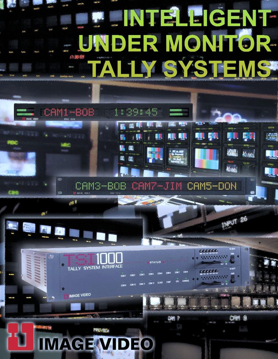
4 UNDER MONITOR DISPLAYS Under monitor displays are the most visible part of any tally system. IMAGE VIDEO Under Monitor Displays provide clear and accurate information for studio & network control rooms, OB trucks, on-air facilities, alarm systems and any other special purpose applications. Tri-color 0.7 LED displays are bright and easy to read Slim 0.9''deep design mounts below or in front of single, dual, or triple monitor bank Over 30 levels of LED brightness to suit most lighting conditions Text formatting controls including alternate character sets, centering, and flashing Loop-thru RJ11 connection to tally system, or any RS-485 / RS-232 serial port Powered by wall-mount adapter Optional central supply powers up to 18 displays Use stand-alone or with tally system Two external tally inputs provide message or color control for stand-alone use TRI-COLOR DISPLAYS IMAGE VIDEO has a wide variety of display models to suit any application. Select from three-color or single-color in 17, 13 and 8.5 wide models. Choose rack or wall mounting, or take advantage of space in front of monitor controls with a unique front-mount mounting system. Build a tally system from any combination of display models. Outfit an entire facility or monitor wall, or start with just a few displays and expand later. To reduce cost, any display can be loaded with fewer than the maximum LED's so you only pay for the display space that you need. SINGLE-COLOR DISPLAYS If color change is not important for displays in some locations, install single-color displays, further reducing cost. If desired, single color displays can include different colored LED end blocks to indicate on-air tally or other conditions.

5 MOUNTING IMAGE VIDEO displays are available in traditional rack mounting, wall mounting, and front-mounting versions. The front-mount is unique because it makes better use of the available rack space. The display tilts down so the video monitor's controls are always accessible. Front mounting is perfect for equipment-saturated facilities where rack space just can't be liberated. STAND-ALONE OPERATION All displays are capable of stand-alone operation. Displays can be configured individually or together through their RS-232 port using a simple terminal or PC communication program. MENU SYSTEM A built-in, easy to use menu system provides access to all set-up, diagnostic, and message functions. Configure displays for a fixed message, or program message or color change reactions to external tally input levels. All display information is retained in non-volatile memory while the display is powered off.

6 UNDER MONITOR DISPLAYS WITH AUDIO METERING The RDU-1518 is a single 17 under monitor display with two channels of audio metering. The RDU-1519 is a dual 17 under monitor display with four channels of audio metering. Only 0.9 deep Dual display has 9 fixed width characters or 11 proportionally spaced characters Single display has 6 to 20 fixed width characters or up to 24 proportionally spaced characters Analog audio VU bargraph meter features 17 segments of resolution Adjustable 0 db reference point STATIC DISPLAYS If color change is needed but the display message changes infrequently, install static displays. Print your own labels on transparencies, then insert labels into displays as needed. Static displays provide the same 'look' as changeable display's, but at reduced cost. Connect the tally system to the display s built-in tally input to change color from green to red to indicate on-air or some other condition. The 7721 series of static displays features a plugable terminal block for tally connections, a brightness control, and a tally color mode selector.

7 TSI-1000ACO AUTO CHANGE OVER FOR TSI-1000 The TSI-1000ACO allows two TSI-1000 tally controllers to be interconnected providing complete redundancy. The status of each TSI-1000 is monitored for correct operation. The TSI-1000ACO automatically switches all tally system operations to the backup TSI Change over function may also be controlled manually. TSI-1000PS For additional redundancy, a TSI-1000 can be fitted with a second hot-swappable power supply. RDU-1510PS /RDU-1610PS In addition to wall-mount power supplies, multi-output rackmount power supplies are available. The RDU-1510PS provides 12 outputs for RDU-1510 series of under monitor displays. The RDU-1610PS provides 18 outputs for RDU-1610 series of under monitor displays. The RDU-1510PS and RDU-1610PS feature front mounted fuses with LED status indicators. Locking power connectors are used to prevent disconnection due to the effects of vibration common in OB vans.

8 TALLY SYSTEM CONSOLE All aspects of tally system operation can be controlled from a Windows PC running the Tally System Console program. The program lets you construct a model of your signal switching system, initially to configure all the equipment in the tally system, or later to make changes that reflect modifications to your system. Although the tally system can operate without a PC, the Tally System Console program has many features that provide additional capabilities to the tally system including: On-screen view of any monitor wall in the system containing the same information as the actual displays On-screen view of individual or grouped displays large enough to see from across a room Interactive editing of any display Adjustable display brightness Addition or removal of tally system equipment even while the tally system is in use

9 Alternate source name feature that allows one or two custom names for each source to give a more descriptive name on the displays than those provided by your signal switching system Multiple configuration files to quickly alter display or tally functions for different applications or operator preferences On-screen virtual displays that function just like real displays (no actual displays are required) Powerful programming language that provides a high level of system-wide or individual display customization
 Powerful programming language that provides a high level of system-wide or individual display")
10 Cam 11 STUDIO 1 ROUTER STUDIO 1 SWITCHER - SERIAL INTERFACE STUDIO 2 SWITCHER - GPI INTERFACE STUDIO 2 ROUTER FACILITY ROUTER REMOTE TALLY INPUTS SWITCHER GPI OUTPUTS Cam 21 MODEL 4211 PARALLEL I/O INTERFACE Cam 12 MODEL 4211 PARALLEL I/O INTERFACE Cam 22 IMAG IDEO Desktop or Laptop computer used for configuration of tally system WINDOWS 95 configuration software included MASTER CONTROL SWITCHER SERIAL INTERFACE

11 SD ROUTING SWITCHER PRODUCTION CONTROL ROUTING SWITCHER RS-422 PORT RS-422 RS-422 ASCII PROTOCOL ROUTER CONTROL SYSTEM PRODUCTION SWITCHER 8 to 40 PARALLEL INPUTS to 40 PARALLEL OUTPUTS TALLY Out puts Cam1 CAMERA TAL LIES Cam2 RS-232 Desktop or Laptop computer used for configuration of tally system WINDOWS 95 configuration software included CAM 1 CAM 2 RS-422 VTR-45 RS-422 PORT MULTI-IMAGE DISPLAY SYSTEM CAM 3 SAT-RC V12 MASTER CONTROL SWITCHER MASTER CONTROL

12 TALLY SYSTEM ORDERING INFORMATION TSI-1000 TALLY SYSTEM INTERFACE TSI-1000E Tally System Interface VAC 50 / 60 Hz TSI-1000E Tally System Interface c/w 10/100 Mbps Ethernet port VAC 50 / 60 Hz Plug-in redundant power supply for TSI VAC 50 / 60 Hz TSI-1000ACO Auto Changeover controller c/w wallmount power supply and interconnect cables 1510 SERIES TRI-COLOR DISPLAYS MODEL 4211 PARALLEL INTERFACE UNITS Interface Unit, no outputs, 40 isolated inputs Interface Unit, no outputs, 40 pull- to-ground inputs Interface Unit, 40 contact closure outputs, 40 isolated voltage inputs Interface Unit, 40 contact closure outputs, 40 pull-to-ground inputs Interface Unit, 40 contact closure outputs, no inputs 1610 SERIES SINGLE-COLOR DISPLAYS STATIC UNDER MONITOR DISPLAYS A two-color LED single display, rack-mount A two-color LED single display, no rack-mount A single display, A single display, 8 1 / B dual display, rack-mount B dual display, 17, no rack-mount E Triple display, rack-mount xA interchangeable legends for 772A and B RDU DUAL DISPLAYS proportional / 13 fixed space characters per side proportional / 8 fixed space characters per side RDU SINGLE DISPLAYS proportional or 26 fixed space characters proportional or 16 fixed space characters proportional or 13 fixed space characters proportional or 8 fixed space characters RDU " SINGLE DISPLAYS proportional or 20 fixed space characters proportional or 13 fixed space characters proportional or 8 fixed space characters RDU / 8" SINGLE DISPLAYS proportional or 13 fixed space characters proportional or 8 fixed space characters MULTIPLE OUTPUT POWER SUPPLIES Powers up to series displays 120V 60 Hz Powers up to series displays 240V 50 Hz Powers up to series displays 120V 60 Hz Powers up to series displays 240V 50 Hz RDU " DUAL DISPLAYS Proportional / 11 fixed space characters per side Proportional / 8 fixed space characters per side RDU " SINGLE DISPLAYS proportional or 23 fixed space characters proportional or 16 fixed space characters proportional or 13 fixed space characters proportional or 8 fixed space characters RDU " SINGLE DISPLAYS proportional or 16 fixed space characters proportional or 13 fixed space characters proportional or 8 fixed space characters RDU / 8" SINGLE DISPLAYS proportional or 10 fixed space characters proportional or 8 fixed space characters WALLMOUNT POWER SUPPLIES VAC 60Hz / 12 1A / Right-Angle Plug VAC 60Hz / 12 1A / Straight Plug Brick Supply 230 VAC 50Hz / 12 1A / Right-Angle Plug / 8 AC cord DISPLAYS WITH AUDIO METERING RDU SINGLE DISPLAYS proportional / 13 fixed space characters proportional / 8 fixed space characters RDU DUAL DISPLAYS proportional / 8 fixed space characters per side proportional / 9 fixed space characters per side RDU SINGLE DISPLAYS proportional / 13 fixed space characters proportional / 8 fixed space characters RDU DUAL DISPLAYS proportional / 8 fixed space characters per side IMAGE VIDEO 1620 Midland Avenue, Toronto, Ontario, Canada, M1P 3C2 Tel: (416) Fax: (416) info@imagevideo.com Other configurations available Printed in Canada

HCS-3600MB2 Conference Main Unit
 HCS-3600MB2 Conference Main Unit Features TCP/IP communication protocol in PC control Remote control, remote diagnosis and remote update Parallel redundancy & multi-room configuration Excellent immunity
Table of Contents. Chapter1. Introduction...1. 1.1 Before Installation... 1 1.2 System Requirements... 1
 Table of Contents Chapter1. Introduction...1 1.1 Before Installation... 1 1.2 System Requirements... 1 Chapter2. IVS-110 1-Channel Internet Video Server...2 2.1 Package Content... 2 2.2 Physical Installation...
Installation and Operation Guide
 www.aja.com Quick Start Guide Introduction This Quick Start Guide provides a basic overview of KUMO configuration. It is not meant as a substitute for the detailed information found in the KUMO Manual,
PRODUCTIVITY THROUGH INNOVATION 600 CONTROL DIRECT DRIVE TECHNICAL/OPERATION MANUAL
 Rev. D PRODUCTIVITY THROUGH INNOVATION 600 CONTROL DIRECT DRIVE TECHNICAL/OPERATION MANUAL 10 BORIGHT AVENUE, KENILWORTH NEW JERSEY 07033 TELEPHONE: 800-524-0273 FAX: 908-686-9317 TABLE OF CONTENTS Page
IPX AUTOMATIC IP NETWORK LOSS BACKUP A/B SWITCH INSTRUCTION BOOK IB6444-02
 IPX AUTOMATIC IP NETWORK LOSS BACKUP A/B SWITCH INSTRUCTION BOOK IB6444-02 TABLE OF CONTENTS DESCRIPTION 2 MOUNTING INSTRUCTIONS 2 HOW TO CABLE THE IPX 2/3 POWER SUPPLY INSTALLATION 3 OPERATION 3 CARE
Web: www.stp.hu; www.logipix.eu; www.walkdvr.com
 StP Technical Development Ltd. version: 1 Contact: Address: 11-13. Késmárk st., 1158 Budapest, Hungary Phone: +36 1 410-0556; +36 20 480-5933 Fax: +36 1 414-0913 E-mail: info@stp.hu Technical support:
B e c a u s e i t m a t t e r s.
 Compact SDI routers. B e c a u s e i t m a t t e r s. Compact SDI routers. Compact, robust and built for critical production environments, KUMO SDI routers offer flexibility and quality that exceeds SMPTE
THE SAS 16000 AUDIO ROUTING SWITCHER
 S A S 1 6 0 0 0 Audio Routing System 32 x 32 in a compact 2 RU package Multi-point RS-485 & RS-232 interfaces Stereo/mono easily integrated within system Many off-the-shelf interconnect options Superb
Compact SDI Routers KUMO 1604 KUMO 1616 KUMO CP
 Compact SDI Routers 1616 KUMO 1604 KUMO 1616 KUMO CP KUMO Compact SDI Routers Compact SDI Routers NEW 1616 Rear Panel 1604 Rear Panel KUMO compact SDI routers are small and cost-effective, yet robust and
USER MANUAL. VS-81H 8x1 HDMI Switcher MODEL: P/N: 2900-000670 Rev 4
 KRAMER ELECTRONICS LTD. USER MANUAL MODEL: VS-81H 8x1 HDMI Switcher P/N: 2900-000670 Rev 4 Contents 1 Introduction 1 2 Getting Started 2 2.1 Achieving the Best Performance 2 2.2 Safety Instructions 3
ALARMS-xx. Remote Alarm Unit Setup Guide 1 2 3 4 5 6 7 8 9 10 11 12 13 14 15 16 17 18 19 20 21 22 23 24 25 26 27 28 29 30 31 32 RESET ALL
 Remote Alarm Unit Setup Guide 1 2 3 4 5 6 7 8 9 10 11 12 13 14 15 16 17 18 19 20 21 22 23 24 25 26 27 28 29 30 31 32 RESET ALL User s Guide Version 1.0 07/01/2009 Michael Stevens & Partners Ltd. has made
Digital Video Recorder
 EN Digital Video Recorder Hardware Quick Start Guide Welcome! Lets get started. QH16_42000914E Swann 2014 1 1 Getting to know your DVR Congratulations on your purchase of Swann s latest DVR security system!
T-6232 10 Zone Weekly Timer
 Economy 10 Zone BGM Solution for School and Factory Zone 1 Microphone cable T-105 5" Ceiling Speaker Aux cable Speaker cable T-6232 (with SD input) 10 Zone Weekly Timer Zone 2 T-601 6W Wall Mount Speaker
Kaleido-Alto: 10-input, highly affordable multi-image display processor
 8 Kaleido-Alto: -input, highly affordable multi-image display processor The compact and highly affordable Kaleido-Alto, -input processor uses the same high quality image display technology as the top of
Programmable set for Ethernet Modbus/TCP in IP67 TI-BL67-PG-EN-2
 Type code Ident no. 1545065 Number of channels 2 Dimensions (W x L x H) 108 x 145 x 77.5 mm CoDeSys-programmable acc. to IEC 61131-3 Cable max. 50 m between interface and read/write head 10/100 Mbps Male
Network Video Recorder
 Network Video Recorder XC-4CH-NVR-1TB and XC-8CH-NVR-2TB Username: admin Password: 12345 Quick Operation Guide XC-4CH-NVR-1TB and XC-8CH-NVR-2TB quick guide TABLE OF CONTENTS NVR Pre-Installation... 2
Berkeley Audio Design Alpha USB
 QUICK USER GUIDE v1.2.2 Berkeley Audio Design Alpha USB The Alpha USB is an asynchronous High Speed USB to digital audio interface designed to provide the highest possible audio quality from computer audio
A+ Guide to Managing and Maintaining Your PC, 7e. Chapter 1 Introducing Hardware
 A+ Guide to Managing and Maintaining Your PC, 7e Chapter 1 Introducing Hardware Objectives Learn that a computer requires both hardware and software to work Learn about the many different hardware components
Network Video Recorder Quick Operation Guide
 Network Video Recorder Quick Operation Guide UD.6L0202B1119A01 Thank you for purchasing our product. If there is any question or request, please do not hesitate to contact dealer. This manual is applicable
Configuring the Switch with the CLI-Based Setup Program
 APPENDIX D Configuring the Switch with the CLI-Based Setup Program This appendix provides a command-line interface (CLI)-based setup procedure for a standalone switch. For product overview information,
INPUT SWITCH OPTIONS:
 RSS6-T RF Channel & Broadband Automatic Switching Station info@tekronsystems.com www.tekronsystems.com 1/7 INTRODUCTION The RSS6-T is designed for the redundancy of analog and QAM RF channels, as well
CABLE ONE ALL DIGITAL
 CABLE ONE ALL DIGITAL The world is going All Digital and so is Cable ONE. With the switch from analog to digital technology, Cable ONE will be able to add new channels, especially more HD channels, and
Fiber Optic Selector Guide for Analog & Digital Data Links, Contact Closures & Multiplexers
 Fiber Optic Selector Guide for Analog & Digital Data Links, Contact Closures & Multiplexers Analog Data Links Multi-Channel Contact Closures Multiplexers Digital Data Links - Contact Closures Power Supply
GTP-32 Control Processor. Overview Operation Web Pages Built-in Diagnostics Event Logs Troubleshooting
 GTP-32 Control Processor Overview Operation Web Pages Built-in Diagnostics Event Logs Troubleshooting GTP-32 Control Processor The GTP-32 Control Processor is a member of the Flex Control Network product
2X1 DVI Switch (DS-21R) 4X1 DVI Switch (DS-41R) USER MANUAL. DTronics Inc.
 4X1 DVI Switch (DS-41R) USER MANUAL. DTronics Inc.") 2X1 DVI Switch (DS-21R) 4X1 DVI Switch (DS-41R) USER MANUAL DTronics Inc. 40 State Highway 94, Suite L2A McAfee, NJ 07428 201-362-1606 Fax: 781-207-0351 UNPACKING Each DVI Link DVI Switch package includes
2X1 DVI Switch (DS-21R) 4X1 DVI Switch (DS-41R) USER MANUAL DTronics Inc. 40 State Highway 94, Suite L2A McAfee, NJ 07428 201-362-1606 Fax: 781-207-0351 UNPACKING Each DVI Link DVI Switch package includes
Temperature & Humidity SMS Alert Controller
 Temperature & Humidity Alert Controller METERS 3 simple steps starting the unit: Insert the SIM card Plug in the sensors connectors Connect the AC power cord. Specifications: AC 90~260V Auto Select Internal
Bristol ControlWave Redundant Control
 October 19, 2007 - Page 1 Bristol ControlWave Redundant Control Redundant systems are offered for critical processes and harsh applications that require maximum operational readiness and system availability.
DS-7208HVI-ST Series DVR. Technical Manual
 DS-7208HVI-ST Series DVR Technical Manual Notices The information in this documentation is subject to change without notice and does not represent any commitment on behalf of HIKVISION. HIKVISION disclaims
Features, Benefits, and Operation
 Features, Benefits, and Operation 2014 Decibel Eleven Contents Introduction... 2 Features... 2 Rear Panel... 3 Connections... 3 Power... 3 MIDI... 3 Pedal Loops... 4 Example Connection Diagrams... 5,6
TrueAlarm Fire Alarm Systems
 TrueAlarm Systems UL, ULC, CSFM Listed; FM Approved* Network Annunciators; es Features Provides a dedicated local area network (LAN) for connection of a TrueSite workstation server to remote clients: es
SCD Server. SCD Server Pro
 SCD Server SCD Server Pro SCD Server & SCD Server Pro 9850-000387-01 - Page 1 of 8 SCD Server and SCD Server Pro The SCD Server is a 2U high DMX generator, running the ZerOS Operating System and emulating
BLACK BOX Scalable matrix KVM switch supports up to 1024 ports with fiber or copper cable.
 ServSwitch DKM DVI-D KVM Matrix Switch Delivers instant switching in four different modes for data center, control room, and classroom settings. BLACK BOX Scalable matrix KVM switch supports up to 1024
Servicom G.R.I.P. Enabling Global Push-to-Talk over BGAN and Fleet Broadband Version 01 30.09.11
 Servicom G.R.I.P. Enabling Global Push-to-Talk over BGAN and Fleet Broadband Version 01 30.09.11 Contents 1 Overview... 1 2 Background... 1 3 Key Features... 2 4 Typical Users... 2 5 Benefits to BGAN and
Delivers instant switching in four different modes for data center, control room, pooling and similar applications.
 ServSwitch DKM & ServSwitch DKM FX Delivers instant switching in four different modes for data center, control room, pooling and similar applications.» Scalable DVI KVM Matrix Switch supports up to 288
Welcome to life on. Get started with this easy Self-Installation Guide.
 Welcome to life on Get started with this easy Self-Installation Guide. Welcome to a network that s light years ahead. Welcome to life on FiOS. Congratulations on choosing Verizon FiOS! You re just a few
AIS750 Series Alarm Annunciator
 Unparallel, modular, multipoint design with Integrated controllers Two Operation Modes (Stand-alone & Serial) All sizes confi gurable up to 440 Alarm Points RS485 / RS232 Serial Communication Manual &
FortiVoice. Version 7.00 Start Guide
 FortiVoice Version 7.00 Start Guide FortiVoice Version 7.00 Start Guide Revision 2 18 October 2011 Copyright 2011 Fortinet, Inc. All rights reserved. Contents and terms are subject to change by Fortinet
Senses SV series industrial monitor user manual
 Industrial Monitors Senses SV series Senses SV19 / SV17 User manual (Issue A) Part No: 85090084 Page 1 of 25 Copyright Copyright 2008 Amplicon Liveline Ltd. All rights reserved. This publication, including
Deliver instant switching in four different modes for data center, control room, pooling, and similar applications.
 ServSwitch DKM and ServSwitch DKM FX KVM Matrix Switches Deliver instant switching in four different modes for data center, control room, pooling, and similar applications. BLACK BOX and DKM FX Features
DS-7608NI-S Series NVR. Technical Manual
 DS-7608NI-S Series NVR Technical Manual Notices The information in this documentation is subject to change without notice and does not represent any commitment on behalf of HIKVISION. HIKVISION disclaims
EV-1000 Series DVR. Quick Operation Guide. Version 1.0.0
 EV-1000 Series DVR Quick Operation Guide Version 1.0.0 Thank you for purchasing our product. If there is any question or request, please do not hesitate to contact dealer. This manual is applicable to
DVI KVM Switches DP-MUX 7.4
 DVI KVM Switches DP-MUX 7.4 KVM Switches Switches for the effective operation of multiple computers via one workstation Leading the way in digital KVM The company Leading the way in digital KVM Guntermann
Frequently Asked Questions
 Frequently Asked Questions Frequently Asked Questions are a quick and easy way to find the answers you need, however if you cannot find the information you are looking for, please contact us by email or
Network and Facility Management: Needs, Challenges and Solutions
 Network and Facility Management: Needs, Challenges and Solutions Graham Jones Harris Broadcast Communications gjones04@harris.com New tools are needed to enable broadcasters to efficiently manage the modern
. ImagePRO. ImagePRO-SDI. ImagePRO-HD. ImagePRO TM. Multi-format image processor line
 ImagePRO TM. ImagePRO. ImagePRO-SDI. ImagePRO-HD The Folsom ImagePRO TM is a powerful all-in-one signal processor that accepts a wide range of video input signals and process them into a number of different
Auditorium Audiovisual System User s Guide
 Auditorium Audiovisual System User s Guide Page Page Contents Introduction...4 Facilities 7 Auditorium floor plan...8 Stage floor boxes and wall plates...9 Other floor boxes and wall plates...10 System
Setup guide. point to point wall plate extenders
 SDS-1002/3 point to point wall plate extenders Setup guide For more information visit our website, or talk to one of our technical team tel: +44 (0) 1306 628264 www.smart-e.co.uk SDS-1002 & 1003 SETUP
Quick Start Guide NVR DS-7104NI-SL/W NVR. www.hikvision.com. First Choice For Security Professionals
 Quick Start Guide NVR DS-7104NI-SL/W NVR NOTE: For more detailed information, refer to the User s Manual on the CD-ROM. You must use your PC or MAC to access the files. www.hikvision.com Quick Start 1.
BridgeWay Fixed Base Radio Telecom VoIP Gateway
 BridgeWay Fixed Base Radio Telecom VoIP Gateway PRODUCT OVERVIEW The BridgeWay Fixed Base system provides SIP and H.323 voice over IP (VoIP) communications interoperability between mobile radio, SATCOM,
DASDEC Interfacing to DM Engineering MSRA/MSRE Series Switchers
 Introduction DASDEC Interfacing to DM Engineering MSRA/MSRE Series Switchers The DASDEC-II EAS/CAP Encoder/Decoders include a single analog balanced-stereo audio switch for inserting an EAS/CAP audio message
Driver Pant 8 and antenna switcher Ant 8. User manual
 Driver Pant 8 and antenna switcher Ant 8 User manual Table of contents Table of contents... 2 Introduction... 3 Shipping Contents... 3 Technical Data... 3 Control Panel... 4 Rear panel... 5 Controller
Applied Electronics. Commercial Dimming System UPDATE NOTICE
 REV. A Applied Electronics Commercial Dimming System UPDATE NOTICE This notice is to inform the end user of an additional feature added to this DP12/2400 dimming unit. This unit has been outfitted with
Verizon 9100EM Router Troubleshooting
 Verizon 9100EM Router Troubleshooting You can use the Power, Internet, and Ethernet lights on the front panel of the Verizon router to help diagnose home networking connectivity problems. Follow the steps
DIGICLIENT 8.0 Remote Agent Software
 DIGICLIENT 8.0 Remote Agent Software MODEL: D17800 Series Instruction Manual English Version 1.0 Copyright 2007 Digimerge Technologies Inc Table of Contents Table of Contents About the DigiClient 8.0...
Vi DANTE TM Card User & Setup Guide
 Vi DANTE TM Card User & Setup Guide The Soundcraft Vi DANTE card is a 64 x 64 interface between a Vi series console and any Dante compatible device from Harman or other 3 rd party manufacturer. The card
DTA INSTALLATION PROCESS & USER GUIDE FOR CHARTER BUSINESS CUSTOMERS
 DTA INSTALLATION PROCESS & USER GUIDE FOR CHARTER BUSINESS CUSTOMERS This guide is intended for owners or managers and front desk personnel. This guide is not intended for guests. Customer Care 1-800-314-7195
Vroom Hardware manual ver. 1.00 Code 114VROOHWE00. Vroom CANBUS USER INTERFACE WITH LCD GRAPHIC DISPLAY AND WITH TEMPERATURE AND HUMIDITY SENSOR
 Vroom CANBUS USER INTERFACE WITH LCD GRAPHIC DISPLAY AND WITH TEMPERATURE AND HUMIDITY SENSOR ENGLISH HARDWARE MANUAL ver. 1.00 CODE 114VROOHWE00 page 1 of 22 Important Important Read these instructions
MANUAL PC1000R INFO@APART-AUDIO.COM
 MANUAL PC1000R INFO@APART-AUDIO.COM Features The APart PC1000R is a professional multisource CD/USB/SD card music player, equipped with balanced and unbalanced analog outputs, coaxial and optical digital
BIT COMMANDER. Serial RS232 / RS485 to Ethernet Converter
 BIT COMMANDER Serial RS232 / RS485 to Ethernet Converter (Part US2000A) Copyrights U.S. Converters 1 Contents Overview and Features... 3 Functions..5 TCP Server Mode... 5 Httpd Client Mode.5 TCP Auto mode....6
HP Advanced Wireless Docking Station. User Guide
 HP Advanced Wireless Docking Station User Guide Copyright 2014, 2015 Hewlett-Packard Development Company, L.P. Intel is a trademark of Intel Corporation in the U.S. and other countries. Windows and Windows
FlexPoint T1/E1 Copper to Fiber Line Driver
 BLACK BOX NETWORK SERVICES MT660A-MM MT661A-SM MT660A-MM-E MT661A-SM-E FlexPoint T1/E1 Copper to Fiber Line Driver CUSTOMER Order toll-free in the U.S.: Call 877-877-BBOX SUPPORT (outside U.S. call 724-746-5500)
LT-82 Stationary IR Transmitter
 LT-82 Stationary IR Transmitter Configuration LT-82-0 (North America) LT-82-02 (Asia, UK) LT-82-03 (Euro) The Listen LT-82 is the heart of a stationary IR listening system. It takes the desired audio signal
Network Video Recorder Quick Operation Guide
 Network Video Recorder Quick Operation Guide UD.6L0202B1283A01 TABLE OF CONTENTS NVR Pre-Installation... 2 NVR Installation... 2 Hard Disk Installation... 2 Front Panel... 4 Rear Panel... 5 Specifications...
CHAPTER 2: USING THE CAMERA WITH THE APP
 TABLE OF CONTENTS OVERVIEW... 1 Front of your camera... 1 Back of your camera... 2 ACCESSORIES... 3 CHAPTER 1: Navigating the Mobile Application... 4 Device List: How to Use this Page... 4 My Messages:
4. Rear View. Function Switches 1. Fixed IP 2. DHCP Floating IP 3. Auto IRIS (DC Driver LENS) 4. Fixed LENS (AES)
 4. Fixed LENS (AES)") 4. Rear View 5 1.STATIC IP 2.DHCP 3.DC IRIS Mini USB 1 2 3 4 5 6 1. ALM-RST 2. ALM-IN 3. ALM-OUT 4. GND 5. RS485-6. RS485 + 1 2 3 4 5 6 7 DC Power Input: DC Jackψ2.1, DC12V---0.5A or higher. LAN/WAN Network
4. Rear View 5 1.STATIC IP 2.DHCP 3.DC IRIS Mini USB 1 2 3 4 5 6 1. ALM-RST 2. ALM-IN 3. ALM-OUT 4. GND 5. RS485-6. RS485 + 1 2 3 4 5 6 7 DC Power Input: DC Jackψ2.1, DC12V---0.5A or higher. LAN/WAN Network
TELECOM HF VHF UHF over IP
 Analog Radio to IP Gateway TELECOM HF VHF UHF over IP The RADITEK of Radio Over IP interfaces are designed to merge the power and flexibility of IP with analog radio equipment and networks. This offers
Network Projector Operation Guide
 Network Projector Operation Guide Table of contents Preparation...3 Connecting the projector with your computer...3 Wired connection... 3 Wireless connection (for selective models)... 4 QPresenter...7
Network Video Recorder. Quick Start Guide XC-16CH-NVR-4TB. Username: admin. Password: 12345. XC-16CH-NVR-4TB quick guide
 Network Video Recorder XC-16CH-NVR-4TB Username: admin Password: 12345 Quick Start Guide XC-16CH-NVR-4TB quick guide TABLE OF CONTENTS NVR Pre-Installation... 2 NVR Installation... 2 Hard Disk Installation...
Lenovo ThinkVision L197 Widescreen LCD Monitor View your images on a wide screen
 Lenovo Europe Announcement ZG08-0333, dated April 15, 2008 Lenovo ThinkVision L197 Widescreen LCD Monitor View your images on a wide screen Description...2 Product positioning... 5 At a glance The Lenovo
How to Determine the Right Fiber Optic Network Backup Switch For Your Application
 How to Determine the Right Fiber Optic Network Backup Switch For Your Application Raymond B. Sepe, Sr. Electro Standards Laboratories 36 Western Industrial Drive Cranston, RI 02921 Telephone: 1-401-943-1164
OPERATION MANUAL. MV-410RGB Layout Editor. Version 2.1- higher
 OPERATION MANUAL MV-410RGB Layout Editor Version 2.1- higher Table of Contents 1. Setup... 1 1-1. Overview... 1 1-2. System Requirements... 1 1-3. Operation Flow... 1 1-4. Installing MV-410RGB Layout
Quick Start Guide. WRV210 Wireless-G VPN Router with RangeBooster. Cisco Small Business
 Quick Start Guide Cisco Small Business WRV210 Wireless-G VPN Router with RangeBooster Package Contents WRV210 Router Ethernet Cable Power Adapter Product CD-ROM Quick Start Guide Welcome Thank you for
USER MANUAL. 914 Power Amplifier MODEL: P/N: 2900-300280 Rev 1
 KRAMER ELECTRONICS LTD. USER MANUAL MODEL: 914 Power Amplifier P/N: 2900-300280 Rev 1 Contents 1 Introduction 1 2 Getting Started 2 2.1 Achieving the Best Performance 2 3 Overview 3 3.1 Energy Star 3
SVC400P/SVC800P. 4/8 Camera Live Tracking Vehicle DVR Installation Manual. Version 1.0
 SVC400P/SVC800P 4/8 Camera Live Tracking Vehicle DVR Installation Manual Version 1.0 1. MAIN FEATURES... 2 2. PRODUCT OVERVIEW... 2 3. DIMENSIONS... 4 4. PACKAGE CONTENTS... 5 5. MOUNTING AND ENVORNMENTAL
Fast Ethernet FX-TX Media Converter. User Manual RINGDALE
 Fast Ethernet FX-TX Media Converter User Manual RINGDALE Introduction The Fast Ethernet FX-TX Media Converter Provides an ideal solution for extending the cable length of your network, or a way of interconnecting
IP DSLAM IDL-2402. Quick Installation Guide
 IP DSLAM IDL-2402 Quick Installation Guide Table of Contents Package Contents... 3 Overview... 4 Setup the IDL series IP DSLAM... 5 Safety Instruction... 5 Hardware Installation... 6 WEB Configuration...
Quareo ICM Server Software
 The Quareo Infrastructure Configuration Manager (ICM) is a server software application designed to document and administer both passive and active network connectivity infrastructure. ICM enables management
Troubleshooting the Verizon MI424WR Router
 Troubleshooting the Verizon MI424WR Router You can use the Power, Internet, and Ethernet lights on the front panel of the Verizon router to help diagnose home networking connectivity problems. Follow the
Meraki MX50 Hardware Installation Guide
 Meraki MX50 Hardware Installation Guide January 2011 Copyright 2010, Meraki, Inc. www.meraki.com 660 Alabama St. San Francisco, California 94110 Phone: +1 415 632 5800 Fax: +1 415 632 5899 Copyright: 2010
Provides one channel for Ethernet over existing
 LB304A LBPS301A LBPS304A Hardened Ethernet Extender Quick Start Guide Provides one channel for Ethernet over existing voice-grade copper twisted-pair wire. copper BLACK wire. BOX Customer Support Information
Dash 8Xe / Dash 8X Data Acquisition Recorder
 75 Dash 8Xe / Dash 8X Data Acquisition Recorder QUICK START GUIDE Supports Recorder System Software Version 2.0 1. INTRODUCTION 2. GETTING STARTED 3. HARDWARE OVERVIEW 4. MENUS & BUTTONS 5. USING THE DASH
Setting Up and Testing the MAX Hardware
 Page 1 of 12 Setting Up and Testing the MAX Hardware This chapter covers these topics: Planning the hardware installation Inserting an expansion card Setting up the hardware Connecting to input power Connecting
Technical Manual. For use with Caller ID signaling types: Belcore 202, British Telecom, & ETSI
 Technical Manual For use with Caller ID signaling types: Belcore 202, British Telecom, & ETSI Caller ID.com WHOZZ CALLING? POS 2 Caller ID Monitoring Unit Technical Manual For use with Caller ID signaling
SecureLinx Spider Duo Quick Start Guide
 SecureLinx Spider Duo Quick Start Guide SecureLinx Spider Duo Quick Start Guide SecureLinx Spider Duo QUICK START GUIDE CONTENTS Overview... 2 What s In The Box... 3 Installation and Network Settings...
Digital Marquee Series
 THE SIMPLE MARQUEE SOFTWARE EMBEDDED WEB SERVER Digital Marquee Series Part # DM-0213-T Part # DM-0113-T Part # DM-0220-T Part # DM-0420-T PRODUCT DESCRIPTION The Digital Marquee Series is a simple and
Displayport Extender via 2 multimode fibers LC Duplex Connector Extends Displayport Link up to 200 meters
 Description Displayport combines the audio and video through an interface. It supports high resolution displays and multiple displays with a single cable, and increases the efficiency and bandwidth of
BMW CAR-PC MONITOR MODEL SPECIFICATION BMW3/5 SERIES. Model Name : BMW-100P Paper Version : Ver 1.0
 BMW CAR-PC MONITOR MODEL SPECIFICATION BMW3/5 SERIES Model Name : BMW-100P Paper Version : Ver 1.0 INDEX Precacution Specification System Composition Product Outline Connector Pin Assignment Installaion
Kaleido-K2: Advanced, modular multi-image display processor
 Kaleido-K: Advanced, modular multi-image display processor The ultra robust and high resolution Kaleido-K multi-image display processor redefines signal monitoring by incorporating all conceivable monitor
T3 Mux M13 Multiplexer
 T3 Mux M13 Multiplexer User Manual [Type the abstract of the document here. The abstract is typically a short summary of the contents of the document. Type the abstract of the document here. The abstract
POS Integration. Prepared by: Binh Nguyen
 POS Integration Prepared by: Binh Nguyen Point of Sale (POS) Compatibility To know whether it is possible to integrate your POS system with our DVR, please check whether the type of printer the POS system
Modular I/O System Analog and Digital Interface Modules
 OPERATING INSTRUCTIONS Modular I/O System Analog and Digital Interface Modules Installation Operation Maintenance Document Information Document ID Title: Operating Instructions Modular I/O System Part
Chapter 1 Connecting the Router to the Internet
 Chapter 1 Connecting the Router to the Internet This chapter describes how to set up the router on your Local Area Network (LAN) and connect to the Internet. It describes how to set up your wireless ADSL
4 / 8 C H A N N E L T R U E H D C C T V S Y S T E M
 HDV 4 channel and 8 channel.qxp_layout 2 17/03/2015 15:01 Page 1 4 / 8 C H A N N E L T R U E H D C C T V S Y S T E M H D V 4 R H D V 8 R H D V 4 K B H D V 4 K D H D V 8 K B H D V 8 K D U S E R M A N U
BRIDGEWAY MOBILE VOIP RADIO-INTERCOM GATEWAY
 BRIDGEWAY MOBILE VOIP RADIO-INTERCOM GATEWAY BRIDGEWAY 8M The 8M system provides Radio over IP (RoIP) communications interoperability between radio base stations, SATCOM, wireless and wire line telephone,
Back-UPS Pro 1300/1500 Installation and Operation
 Back-UPS Pro 1300/1500 Installation and Operation Inventory Safety Do not install the Back-UPS in direct sunlight, in excessive heat, humidity, or in contact with fluids. Connect the battery bu059a bu058a
High-density rack with SNMP management provides E1/T1 and Ethernet services over copper and fiber. Data Sheet
 Where to buy > See the product page > High-density rack with SNMP management provides E1/T1 and Ethernet services over copper and fiber Up to 24 Ethernet ports and up to 192 E1/T1 links over fiber and
Moxa EtherDevice Switch
 Moxa EtherDevice Switch EDS-205 Hardware Installation Guide Third Edition, June 2008 2008 Moxa Inc., all rights reserved. Reproduction without permission is prohibited. P/N: 1802002050000 Overview The
2014 AT&T Intellectual Property. All rights reserved. AT&T, Globe logo and other marks are trademarks of AT&T Intellectual Property.
 AT&T Business in a Box Quick Start Guide Please ensure that you have set-up the equipment before the date scheduled with your AT&T Order Manager for Test and Turn Up of your service What s in the Box The
Uninterruptible Power Supply
 96-01101 / rev. 2e / 2-2-12 Uninterruptible Power Supply EXCEPTIONAL SUPPORT & PROTECTION Uninterruptible Power Supply with Energy Saver design that is optimized to address the needs of A/V systems Features
System Wiring Design Guide
 System Wiring Design Guide This guide will help demonstrate the various types of wiring solutions available when connecting video surveillance cameras to EZ Watch Pro and Armor Pro Digital Video Recorders.