INNOVATIVE LOCALIZER ANTENNA BEATS THE ODDS Mel King Manager Flight Inspection Airways Corporation of New Zealand Ltd.
|
|
|
- Basil Jacobs
- 7 years ago
- Views:
Transcription
1 INNOVATIVE LOCALIZER ANTENNA BEATS THE ODDS Mel King Manager Flight Inspection Airways Corporation of New Zealand Ltd. Wellington International Airport runway is built on a narrow neck of land. The south end of the runway finishes adjacent to the open sea of Cooks Strait whilst the Northern end finishes adjacent to Wellington harbour. The photograph below illustrates this layout Inline ILS systems serving both approaches were first installed some 30 years ago. The localizers associated with those ILS s had their 8 element antenna systems mounted down the bank at each end of the runway strip so as to avoid penetrating Obstruction Clearance Surfaces. This arrangement also provided protection for the antenna system from direct jet blast. The next photo shows the previous antenna in this configuration

2 In order to provide for a runway end safety area at the Southern end of the runway the runway strip needed to be extended over an existing roadway and up to the edge of an existing wave trap. There was no possibility of locating a Localizer antenna down the bank into the wave trap and so there began consideration of locating a reduced height antenna on the surface of and at the end of the RESA adjacent to the wave trap. Issues faced in accomplishing this were threefold Antenna height - Obstruction Clearance Surface requirements limited the total available height for the new Localizer antenna to no greater than one metre. This restriction could impact adversely upon both the Localizer antenna element matching as well as the achieved Localizer coverage. Salt Spray protection - During Southerly Storm weather conditions a significant quantity of sea spray is dumped over and beyond the wave trap at the southern end of the runway. Sea spray had already been a cause of shutdown with the previous 8 Element Localizer antenna. With the new Localizer antenna located closer to the sea the problem of spray dump is much greater. Jet Blast Protection - The new Localizer antenna would be only 53 metres from the runway starter extension. At this distance the antenna could be subjected to jet blast wind speeds greater than its design limit.

3 Antenna Height Issue To check the effect upon the antenna element matching a single antenna element was mounted on a variable height support and the Input feed VSWR measured at various heights. The following plot shows that matching was not going to be a problem and was best at around 600mm height Thales{Wilcox} Localizer LPD Input SWR versus height Input SWR Graph 1 -Height above ground surface - mm Localizer coverage issue-the difference in signal strength in the user airspace between a down the bank mounted 8 element antenna and a normal height [1.8m] surface mounted 8 element antenna is approximately 10dB. A graph of the relative signal level versus height for a surface mounted array is displayed in the next plot. This shows the 10dB reduction occurs around 0.55m height. This suggested a suitable minimum height to mount the antenna array. Graph 2 -Signal level relative to 1.8m [Normal] antenna height Gain relative to 1.8m height Height above ground - metres

4 Whilst a low mounted antenna system appeared to potentially match the coverage of the previous down the bank system it was decided to add some margin by using a 14 element array together with placing the equipment room underground immediately below the antenna array in order to minimize cable loss. Thus we were confident that we would achieve a coverage not less than that previously obtained with the down the bank antenna. Protection from Sea Spray Dump

5 To investigate protection measures we firstly undertook tests upon a single antenna element to determine what parts were most sensitive to the presence of salt water. The test setup is illustrated below. Signal Generator Directional Coupler Antenna under test Far field sampling Antenna A B Vector Voltmeter Phase Amplitude Oscilloscope Adaptor Laptop PC

6 Test equipment Location

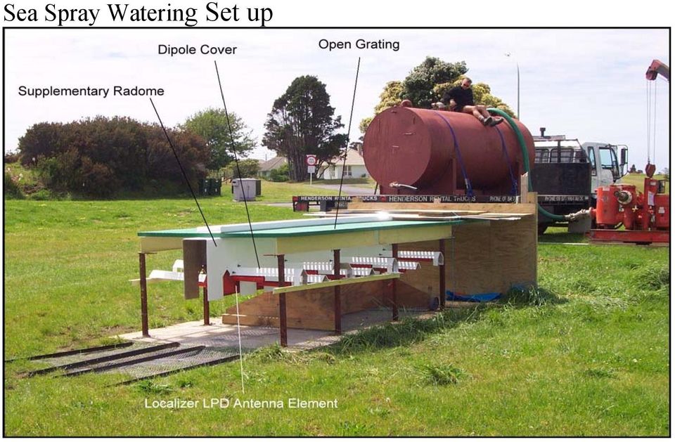
7 Sea Spray Watering Set up
8 Sea Spray Simulation Sea Spray Dump Test Results No Protection Salt Spray test- No Protection 1000 Phase Amplitude 20 per. Mov. Avg. (Phase) 20 per. Mov. Avg. (Amplitude) dB Normal level 400 Am plitude - m V Degrees Spray duration Elapsed time - seconds

9 Sea Spray Test results Grating plus Radome plus Dipole covers Salt Spray Test - Open Grating+Radome+D/covers 1000 Phase Amplitude 20 per. Mov. Avg. (Phase) dB Amplitude - mv Degrees Spray duration Elapsed time - seconds Sea Spray Test Results Radome plus Dipole covers Salt Spray test- No Grating+Radome+D/covers Phase Amplitude dB Change-mV Degrees Spray duration Elapsed time - Seconds

10 Sea Spray Test results Radome plus Dipole Lips Salt Spray Test- Radome+D/Lips 1000 Phase Amplitude 20 per. Mov. Avg. (Phase) 20 per. Mov. Avg. (Amplitude) dB 400 Amplitude - mv Degrees Spray duration Elapsed time -Seconds Final Protection Configuration

11 This final protection configuration reduced the signal amplitude disturbance to an insignificant amount. The signal phase disturbance remained essentially the same as with the full dipole covers. Overall this final protection scheme provided around a 2:1 improvement for signal phase disturbance over having no protection. These single antenna results were then inserted into a computer model of the 14 LPD antenna array proposed for the new Runway 16 localizer. For this simulation a spray fan 7.5m wide [i.e. covering three antennas at a time] sweeping across the array from West to East was used as this was considered to best replicate what happened in reality. The diagram following shows the resulting prediction of the Localizer Course disturbance with and without the protection measures applied. This shows that the protection measures applied would likely overcome Localizer outage during Southerly storm conditions. Effect of sea spray sweeping across Localizer Antenna Array Note Spray fan 7.5metre wide Unprotected Antenna Array ICAO Course deviation limit Protected Antenna Array Course deviation- DDM Relative position of spray fan [0=centre of Array]
![These single antenna results were then inserted into a computer model of the 14 LPD antenna array proposed for the new Runway 16 localizer. For this simulation a spray fan 7.5m wide [i.e. covering three antennas at a time] sweeping across the array from West to East was used as this was considered to best replicate what happened in reality.](/docs-images/48/19136600/images/page_11.jpg "The diagram following shows the resulting prediction of the Localizer Course disturbance with and without the protection measures applied.")
12 With the supplementary protective radome in place there remained the possibility of salt contamination building up over time on the antenna radome. To address this possibility a fresh water spray cleaning system was installed. The configuration of this cleaning system is illustrated below. Fresh water plastic feed pipes Supplementary Radome cover Spray Nozzle Antenna Dipole Element Antenna Radome

13 Each antenna is equipped with fourteen spray nozzles [seven along each side] to clear away any salt accumulation. The fresh water supply to each antenna is controlled by a solenoid operated valve, and the fourteen antennas are washed in pairs symmetrically displaced about the Localizer array centreline. To determine the minimum quantity of water needed for the wash a test rig was setup. This consisted of a short length of transmission line placed on one side of a fibre glass sheet [to simulate the antenna feed arrangement] with a spray nozzle above. The impedance of the transmission line was monitored using an RF Bridge. The sheet was encrusted with a dry salt layer and then sprayed at various water rates and patterns noting the time taken for impedance change to stabilize back to normal. This test resulted in adopting a fine mist fan spray with a flow rate of 0.6 litres/minute which equated to 16.8 litres per minute for each of the seven antenna pairs. At this rate a heavy salt accumulation was cleared in approximately 12 seconds. The setup for this test is shown below.

14 Jet Blast protection. The largest aircraft using the airport is the Boeing 767. A plot of the Jet blast velocity versus distance is shown below. It will be seen that at 53m distance behind the aircraft the exhaust air velocity is greater than 100mph.

15 Clearly it was possible that the wind speed design limit for the Localizer antenna array could be exceeded. Therefore a jet blast deflector needed to be placed directly in front of the array. Electrically the deflector design should introduce minimum attenuation to the localizer signal from the Array. A design was conceived employing a comb like structure having only vertical aligned metal strips. Furthermore the dimensions were tailored such that the top of comb presented high impedance between adjacent strips. The configuration of this prototype is shown below. Prototype Jest Blast Deflector With this prototype jet blast deflector placed immediately in front of the Test antenna at a minimum possible distance, no change in either the amplitude or phase of the far field received signal was detected. Following this test the prototype design was modeled and tested in a wind tunnel to determine whether the reduction in wind speed would be adequate. The following picture shows the wind tunnel model.

16 Prototype Jet Blast Deflector Wind Tunnel Model

17 Having completed the design concepts it was then the task of the Structural engineers to replicate the basic form of the prototype deflector into a practical piece of hardware complete with the necessary shear pins to provide for a frangible structure. The following pictures show the final design as installed on site.

18 It was a requirement that there be no interruption to the ILS service during the period of this RESA construction. To achieve this much of the Civil Work was carried out late at night. The new Localizer had to be installed and commissioned into service before the previous Localizer was removed. As part of this process a reinforcing mesh screen was laid along the edge of the roadway underpass to ensure that this edge was electrically parallel to the New Localizer antenna array until the gulley remaining between the underpass and the old localizer had been backfilled.

19 Finale To date sea spray dump has not caused shutdown of the new Localizer. Flight Inspection recorded the coverage to be slightly better than for the previous Localizer installation and comfortably meets the ICAO 18/10nm alternative criteria. The testing to prove the concept was conducted during 2004 and The civil works began in 2006 and the new Localizer was commissioned in Work has commenced to install a similarly configured Localizer but without the sea spray protection, on the opposite approach [Runway 34] Mel King is a Navigation Aids Engineer heading the New Zealand Airways Corporation Flight Inspection Unit. He has also been a serving member of the International Committee for Airspace Standards and Calibration since 1996.

20 C U R R I C U L U M V I T A E NAME: NATIONALITY: Mel King New Zealand BORN: 12 th May 1932 APPOINTMENT: FIRM: Manager Flight Inspection and Systems Engineer Airways Corporation of New Zealand Ltd BACKGROUND Mel King is a professional engineer with an electrical and electronics engineering background spanning some 50 years and focusing on radio-navigation systems and flight inspection. He has been widely involved in a number of major projects during this period featuring all aspects of planning and implementation. His expertise and experience includes financial management, maintenance activities and responsibility for those sections providing air navigation services. Mr King has held high office in government civil aviation administration and management, including appointments as Assistant Director of Civil Aviation and Chief Engineer. He has been an adviser with the International Civil Aviation Organisation (ICAO) on behalf of the United Nations Development Program (UNDP) and currently is a serving member on the International Committee for Airspace Standards and Calibration. KEY EXPERIENCES Assistant Director Technical Development with the then Civil Aviation Department of the New Zealand Ministry of Transport, responsible for technical and engineering standards and compliance with ICAO requirements for an air traffic services system. Chief Engineer Navigation Aids with the New Zealand Civil Aviation Department, responsible for planning, procurement and installation of navigation facilities in New Zealand and the Pacific Islands through the New Zealand overseas aid development programme. Development of life cycle cost management standards for technical equipment. Negotiating flight inspection contracts for navigation aid checking. Experiences at all aspects of project management and its related definition, evaluation, costbenefit, schedule, negotiating, financial and analytical skills. Vice-Chairman of the International Committee for Airspace Standards and Calibration. 1

21 Development and implementation of Global Navigation Satellite System flight inspection capability. PROFESSIONAL MEMBERSHIPS Member, Institution of Professional Engineers of New Zealand (MIPENZ) Member, Institution of Electrical Technology IET(United Kingdom). EXPERIENCE 1991-Present 1991-Present Airways Corporation of New Zealand Ltd Systems Engineer Flight Inspection and Manager Flight Inspection Responsible for: managing flight inspection services defining and maintaining flight inspection standards and procedures analysing and maintaining flight inspection records researching flight inspection methods and system undertaking flight inspection engineering duties throughout New Zealand and Indo-Asia-Pacific regions Self employed Consulting engineer in the aviation industry specialising in radio navigation aids and flight inspection International Civil Aviation Organization Expert Appointment with ICAO as Flight Calibration (Inspection) Adviser, under the United Nations Development Programme, to provide technical assistance in Tanzania, East Africa. The purpose of this position was to establish a Flight Inspection Unit for the Eastern-Southern African States New Zealand Ministry of Transport, Civil Aviation Department 1986 Assistant Director Technical Development Responsible for the overall management for communications, navigation and surveillance systems and airfield electrical systems for New Zealand Chief Engineer Navigation Aids Responsible for planning, procurement and implementation of radio navigation facilities in New Zealand, and in Pacific islands states through the New Zealand overseas aid development programme. 2
22 Aeronautical Systems Engineering Positions (various) Employed in a variety of positions with the New Zealand Ministry of Transport, specialising in aeronautical electrical and electronic systems. 3
Communication, Navigation, Surveillance (CNS) engineers and executives of Airports Authority of India
 engineers and executives of Airports Authority of India") Communication, Navigation, Surveillance (CNS) engineers and executives of Airports Authority of India CNS Officers Guild 1 Airports Authority of India (AAI) is entrusted with responsibility of providing
Communication, Navigation, Surveillance (CNS) engineers and executives of Airports Authority of India CNS Officers Guild 1 Airports Authority of India (AAI) is entrusted with responsibility of providing
Determination of ILS Critical and Sensitive Areas: A Comparison of Flight Measurement versus Simulation Techniques
 Determination of ILS Critical and Sensitive Areas: A Comparison of Flight Measurement versus Simulation Techniques S. Dale Courtney Senior Navigation Engineer US FAA, Air Traffic Organization Washington,
Avaya WLAN 9100 External Antennas for use with the WAO-9122 Access Point
 Avaya WLAN 9100 External Antennas for use with the WAO-9122 Access Point Overview To optimize the overall performance of a WLAN in an outdoor deployment it is important to understand how to maximize coverage
Antenna Basic Concepts
 ANTENNA An antenna is a device to transmit and/or receive electromagnetic waves. Electromagnetic waves are often referred to as radio waves. Most antennas are resonant devices, which operate efficiently
Aircraft Noise Control at London Luton Airport. August 2015
 Aircraft Noise Control at London Luton Airport August 2015 Aircraft Noise Control at London Luton Airport Foreword London Luton Airport (LLA) continues to place aircraft noise high on its agenda. We recognise
TESTS OF 1 MHZ SIGNAL SOURCE FOR SPECTRUM ANALYZER CALIBRATION 7/8/08 Sam Wetterlin
 TESTS OF 1 MHZ SIGNAL SOURCE FOR SPECTRUM ANALYZER CALIBRATION 7/8/08 Sam Wetterlin (Updated 7/19/08 to delete sine wave output) I constructed the 1 MHz square wave generator shown in the Appendix. This
TP 308 IMPACT STUDY TORONTO BILLY BISHOP/TORONTO CITY AIRPORT. for
 TP 308 IMPACT STUDY TORONTO BILLY BISHOP/TORONTO CITY AIRPORT for May, 2013 TABLE OF CONTENTS Report TAB 1 Map1: Runway 08-26 Extension TAB 2 Maps 2 & 3: Runway 08-26 Obstacle Assessment TAB 3 Canada Air
ILS Replacement. ACI World Safety Seminar. 18 19 November 2008 Kempinski Hotel Beijing Lufthansa Centre
 ILS Replacement Xiaosong Xiao, PhD Tetra Tech, Inc. Orlando, USA Contents: Ground-Based Navigation ILS Approach GNSS/SBAS Approach Comparisons between ILS and GNSS Example: Cost Analysis Between LAAS and
Antenna Deployment Technical Brief
 ProCurve Networking Antenna Deployment Technical Brief Introduction... 2 Antenna types... 2 Omni directional antennas... 2 Directional antennas... 2 Diversity antennas... 3 High gain directional antennas...
APPLICATION PROCEDURES FOR PLACEMENT OF UNDERGROUND WATER AND SEWER PIPELINES IN THE VICINITY OF TRANSPORTATION FACILITIES UNDER THE
 APPLICATION PROCEDURES FOR PLACEMENT OF UNDERGROUND WATER AND SEWER PIPELINES IN THE VICINITY OF TRANSPORTATION FACILITIES UNDER THE JURISDICTION OF ALBERTA TRANSPORTATION 1.0 Application Procedures 2.0
At the completion of this guide you should be comfortable with the following:
 This guide provides instructions and best practices for deployment of the Yealink W52P IP DECT phones and repeaters RT10, which is intended for qualified technicians (or administrator) who will deploy
AVIATION TRAINING ACADEMY
 ATNS ATA Private Bag X 1 Bonaero Park South Africa 1622 Tel nr: +27(11) 961-0100; Fax nr: +27(11) 392-3868; Website: www.atns.co.za. AVIATION TRAINING ACADEMY AERODROME FLIGHT INFORMATION SERVICE COURSE
Interference. Physics 102 Workshop #3. General Instructions
 Interference Physics 102 Workshop #3 Name: Lab Partner(s): Instructor: Time of Workshop: General Instructions Workshop exercises are to be carried out in groups of three. One report per group is due by
Applications in EMC testing. Outline. Antennas for EMC Testing. Terminology
 Antennas for EMC Testing Zhong Chen ETS-Lindgren 1301 Arrow Point Drive Cedar Park, TX 78613 Zhong.Chen@ets-lindgren.com Outline EMC Terms and Definitions Typical EMC Antennas Calibration of EMC Antennas
Low Level Windshear Alert System (LLWAS) An integral part of the U.S. FAA Wind-shear safety program
 An integral part of the U.S. FAA Wind-shear safety program") Low Level Windshear Alert System (LLWAS) An integral part of the U.S. FAA Wind-shear safety program Low-level windshear is a hazard to aircraft in the airport runway corridors. With Climatronics LLWAS,
Low Level Windshear Alert System (LLWAS) An integral part of the U.S. FAA Wind-shear safety program Low-level windshear is a hazard to aircraft in the airport runway corridors. With Climatronics LLWAS,
Cable Analysis and Fault Detection using the Bode 100
 Cable Analysis and Fault Detection using the Bode 100 By Stephan Synkule 2014 by OMICRON Lab V1.3 Visit www.omicron-lab.com for more information. Contact support@omicron-lab.com for technical support.
Antenna Trainer EAN. www.edibon.com. Technical Teaching Equipment INTRODUCTION
 Antenna Trainer EAN Technical Teaching Equipment Products Products range Units 3.-Communications INTRODUCTION Antennas are the main element of aerial communications. They are the transition between a transmission
Printed Dipole Array Fed with Parallel Stripline for Ku-band Applications
 Printed Dipole Array Fed with Parallel Stripline for Ku-band Applications M. Dogan 1, 3,K. Özsoy 1, 2, and I.Tekin 1, 1 Electronics Engineering, Sabanci University, Istanbul, Turkey 2 Vestek Electronic
ELECTRON SPIN RESONANCE Last Revised: July 2007
 QUESTION TO BE INVESTIGATED ELECTRON SPIN RESONANCE Last Revised: July 2007 How can we measure the Landé g factor for the free electron in DPPH as predicted by quantum mechanics? INTRODUCTION Electron
Aviation Training Academy
 Aviation Training Academy ATNS Aviation Training Academy INDEX About ATNS The ATNS Aviation Training Academy ATNS ATA courses Training partnerships Other services offered by ATNS Our satisfied customers
CIVIL AVIATION REQUIREMENTS SECTION 9 AIR SPACE AND AIR TRAFFIC MANAGEMENT SERIES 'D' PART VI
 GOVERNMENT OF INDIA OFFICE OF DIRECTOR GENERAL OF CIVIL AVIATION TECHNICAL CENTRE, OPP SAFDARJANG AIRPORT, NEW DELHI CIVIL AVIATION REQUIREMENTS SECTION 9 AIR SPACE AND AIR TRAFFIC MANAGEMENT SERIES 'D'
ISS Minimalist Antenna
 ISS Minimalist Antenna The purpose of this project was to develop an antenna suggestion that would allow for a simple to duplicate, affordable antenna solution for reasonable access to signals transmitted
NZQA registered unit standard 26968 version 1 Page 1 of 8. Apply knowledge of aircraft radio systems to the certification of aeronautical maintenance
 Page 1 of 8 Title Apply knowledge of aircraft radio systems to the certification of aeronautical maintenance Level 6 Credits 30 Purpose This knowledge-based unit standard is one of a series intended for
Hospital Heliport Inspection Basics
 Hospital Heliport Inspection Basics Eric Peltier Aviation Representative Office of Aeronautics 222 E Plato Blvd St. Paul, MN 55107 651 234 7184 eric.peltier@state.mn.us Sources FAA AC 150/5390 2C Heliport
RESPONSE TIME INDEX OF SPRINKLERS
 , Number l, p.1-6, 29 RESPONSE TIME INDEX OF SPRINKLERS C.K. Sze Department of Building Services Engineering, The Hong Kong Polytechnic University, Hong Kong, China ABSTRACT The Plunge test would be carried
Cooking at the Speed of light!
 Cooking at the Infrared Cooking & Colouring Infrabaker is a modular infrared continuous cooking system developed by Infrabaker International. The machine is designed to cook and/or put colour on a wide
Installation Instructions Hustler 6-BTV Trap Vertical
 Installation Instructions Hustler 6-BTV Trap Vertical ASSEMBLY 1. Check the package contents against the parts list on page 2. 2. WARNING. Installation of this product near power lines is dangerous. For
This presentation reports on the progress made during the first year of the Mapping the Underworld project. As multiple Universities and Departments
 This presentation reports on the progress made during the first year of the Mapping the Underworld project. As multiple Universities and Departments are involved with the project, a single speaker will
Pillbox Antenna for 5.6 GHz Band Dragoslav Dobričić, YU1AW dragan@antennex.com
 Pillbox Antenna for 5.6 GHz Band Dragoslav Dobričić, YU1AW dragan@antennex.com Introduction The pillbox or cheese antenna is made of two parallel plates which are connected to the narrow strip of parabolic
CABLES CABLES. Application note. Link Budget
 CABLES CABLES radiating Link Budget 3. 1. LINK BUDGET The basic elements to calculate a link budget can be illustrated by considering the example shown in Figure 4. It involves a GSM 900 radio coverage
ECE 435 INTRODUCTION TO THE MICROWAVE NETWORK ANALYZER
 ECE 435 INTRODUCTION TO THE MICROWAVE NETWORK ANALYZER Latest revision: October 1999 Introduction A vector network analyzer (VNA) is a device capable of measuring both the magnitude and phase of a sinusoidal
INTEGRITY AND CONTINUITY ANALYSIS OCTOBER TO DECEMBER 2013 QUARTERLY REPORT FROM GPS. Integrity and Continuity Analysis 08/01/14 08/01/14 08/01/14
 INTEGRITY AND CONTINUITY ANALYSIS FROM GPS OCTOBER TO DECEMBER 2013 QUARTERLY REPORT Prepared by: M Pattinson (NSL) 08/01/14 Checked by: L Banfield (NSL) 08/01/14 Approved by: M Dumville (NSL) 08/01/14
AIRCRAFT WARNING LIGHTS
 AIRCRAFT WARNING LIGHTS Ing. Pierangelo Lodolo, ing. Giuseppe Menta Calzavara S.p.a 1. Summary are lighting devices used to make tall structures more visible to aircrafts, during both daytime and nighttime.
TI GPS PPS Timing Application Note
 Application Note Version 0.6 January 2012 1 Contents Table of Contents 1 INTRODUCTION... 3 2 1PPS CHARACTERISTICS... 3 3 TEST SETUP... 4 4 PPS TEST RESULTS... 6 Figures Figure 1 - Simplified GPS Receiver
SIGNAL GENERATORS and OSCILLOSCOPE CALIBRATION
 1 SIGNAL GENERATORS and OSCILLOSCOPE CALIBRATION By Lannes S. Purnell FLUKE CORPORATION 2 This paper shows how standard signal generators can be used as leveled sine wave sources for calibrating oscilloscopes.
Lab Exercise 1: Acoustic Waves
 Lab Exercise 1: Acoustic Waves Contents 1-1 PRE-LAB ASSIGNMENT................. 2 1-3.1 Spreading Factor: Spherical Waves........ 2 1-3.2 Interference In 3-D................. 3 1-4 EQUIPMENT........................
Ultrasonic Wave Propagation Review
 Ultrasonic Wave Propagation Review Presented by: Sami El-Ali 1 1. Introduction Ultrasonic refers to any study or application of sound waves that are higher frequency than the human audible range. Ultrasonic
13.0. Safety Management and Airspace Protection
 13.0 Safety Management and Airspace Protection 13.1 Safety management 119 13.2 Security 119 13.3 Airspace protection 119 13.4 Airports (Protection of Airspace) Regulations 1996 120 13.5 Engine-out procedures
Investment Projects - Health Safety & Environment Good Practice Guide
 Introduction In the absence of a Network Rail standard covering remedial work to existing cable routes, this document is to provide guidance on the standard of refurbishment required when undertaking the
Policy document on the provision of waste & recycling collection and storage facilities. Includes both domestic and commercial premises
 Policy document on the provision of waste & recycling collection and storage facilities Includes both domestic and commercial premises Introduction This document is intended to help relevant parties who
Efficient 2 meter Disguise Antenna Made From a TV Satellite Dish
 Efficient 2 meter Disguise Antenna Made From a TV Satellite Dish This horizontal slot antenna, cut into the reflector of a TV dish, is both the master of disguise and high in performance. By John Portune
Academy of Model Aeronautics. Requirements for the Operation of Remote Control (RC) Aircraft at Full Scale Airshows
 Aircraft at Full Scale Airshows") 1. Background: Academy of Model Aeronautics Requirements for the Operation of Remote Control (RC) Aircraft at Full Scale Airshows Over the years, many AMA member clubs have performed at full-scale airshows.
1. Background: Academy of Model Aeronautics Requirements for the Operation of Remote Control (RC) Aircraft at Full Scale Airshows Over the years, many AMA member clubs have performed at full-scale airshows.
Various Technics of Liquids and Solids Level Measurements. (Part 3)
") (Part 3) In part one of this series of articles, level measurement using a floating system was discusses and the instruments were recommended for each application. In the second part of these articles,
(Part 3) In part one of this series of articles, level measurement using a floating system was discusses and the instruments were recommended for each application. In the second part of these articles,
WiMo Antennen und Elektronik GmbH Am Gäxwald 14, D-76863 Herxheim Tel. (07276) 96680 FAX 9668-11
 96680 FAX 9668-11") The I-PRO Traveller part no. 11440 Thank you for your purchase, please take your time to digest some of the important building tips and the essential matching/adjustment techniques. You will need 8m of
The I-PRO Traveller part no. 11440 Thank you for your purchase, please take your time to digest some of the important building tips and the essential matching/adjustment techniques. You will need 8m of
Phase II Design for a Multiband LMR Antenna System
 Phase II Design for a Multiband LMR Antenna System S. Ellingson and R. Tillman Aug 30, 2011 Contents 1 Introduction 2 2 System Design 2 3 Antenna Tuner 3 Bradley Dept. of Electrical & Computer Engineering,
Fixed Access Ladders. Table of Contents. 1. Legislative Requirements
 Fixed Access Ladders Engineering Data Sheet 2-04 Revised: January 1997 Table of Contents 1. Legislative Requirements 2. General 3. Rungs 4. Side Rails 5. Safety Cages 6. Attachment & Anchoring 7. Platforms
ETL listed for installations within 5 ft. (1.5M) of outer edge of water www.srsmith.com 79-15152-00 Rev E2 9.14 Page 1 of 10
 of outer edge of water www.srsmith.com 79-15152-00 Rev E2 9.14 Page 1 of 10") Color Light Streams Large Laminar Installation Manual (CLSLL) Input Power: Total Power: 12V AC 5W 4008814 ETL listed for installations within 5 ft. (1.5M) of outer edge of water 79-15152-00 Rev E2 9.14
Color Light Streams Large Laminar Installation Manual (CLSLL) Input Power: Total Power: 12V AC 5W 4008814 ETL listed for installations within 5 ft. (1.5M) of outer edge of water 79-15152-00 Rev E2 9.14
Machine Foundation Design
 Machine Foundation Design As the structural engineer who recently designed the machine foundation for one of the largest vertical turning and milling centers in the country, in addition to over 250 other
You will need the following pieces of equipment to complete this experiment:
 UNIVERSITY OF TORONTO FACULTY OF APPLIED SCIENCE AND ENGINEERING The Edward S. Rogers Sr. Department of Electrical and Computer Engineering ECE422H1S: RADIO AND MICROWAVE WIRELESS SYSTEMS EXPERIMENT 3:
FXA 2008. UNIT G484 Module 2 4.2.3 Simple Harmonic Oscillations 11. frequency of the applied = natural frequency of the
 11 FORCED OSCILLATIONS AND RESONANCE POINTER INSTRUMENTS Analogue ammeter and voltmeters, have CRITICAL DAMPING so as to allow the needle pointer to reach its correct position on the scale after a single
Minimum Safety Requirements for temporary Helicopter Landing Areas.
 GOVERNMENT OF INDIA OFFICE OF DIRECTOR GENERAL OF CIVIL AVIATION TECHNICAL CENTRE, OPP SAFDARJANG AIRPORT, NEW DELHI CIVIL AVIATION REQUIREMENTS SECTION 4 - AERODROME STANDARDS & AIR TRAFFIC SERVICES SERIES
SPECIFICATIONS. Recommended Battery sizes (Maintenance) AUTOMOTIVE 150 650CCA 150 750CCA MARINE 200 700MCA 200 850MCA DEEP CYCLE 17 55Ah 17 80Ah
 AUTOMOTIVE 150 650CCA 150 750CCA MARINE 200 700MCA 200 850MCA DEEP CYCLE 17 55Ah 17 80Ah") WARNING Read the operating instructions before use. Lead Acid Batteries can be dangerous. Ensure no sparks or flames are present when working near batteries. Eye protection should be used. Make sure the
WARNING Read the operating instructions before use. Lead Acid Batteries can be dangerous. Ensure no sparks or flames are present when working near batteries. Eye protection should be used. Make sure the
Planning requirements for heliports and helicopter landing sites
 Practice Note 75 December 2012 Planning requirements for heliports and helicopter landing sites The purpose of this practice note is to: 1. Explain how helicopter activity is regulated by the planning
THE COMPOSITE DISC - A NEW JOINT FOR HIGH POWER DRIVESHAFTS
 THE COMPOSITE DISC - A NEW JOINT FOR HIGH POWER DRIVESHAFTS Dr Andrew Pollard Principal Engineer GKN Technology UK INTRODUCTION There is a wide choice of flexible couplings for power transmission applications,
Recognition of overseas flight crew licences and ratings
 Recognition of overseas flight crew licences and ratings Introduction Introduction... 1 Background information... 1 Short term validation of overseas flight crew licences... 2 Flight crew licence issue
JAMAICA CIVIL AVIATION AUTHORITY JOB SPECIFICATION & DESCRIPTION
 JAMAICA CIVIL AVIATION AUTHORITY JOB SPECIFICATION & DESCRIPTION JOB SPECIFICATION JOB TITLE: DIVISION: Deputy Director General - Regulatory Affairs Regulatory Affairs DEPARTMENT: UNIT/LOCATION: Head Office
Gas Meter Clearances and Service Installation Requirements
 March 2016 Gas Meter Clearances and Service Installation Requirements Builder/Owner/Developer Requirements Call PSE's Customer Construction Services 1 888 321 7779 or visit PSE.com/CustomerConstruction
Troubleshooting Problems Affecting Radio Frequency Communication
 Troubleshooting Problems Affecting Radio Frequency Communication Document ID: 8630 Refer to the Cisco Wireless Downloads (registered customers only) page in order to get Cisco Aironet drivers, firmware
WASTE STORAGE AND COLLECTION GUIDANCE FOR NEW DEVELOPMENTS
 WASTE STORAGE AND COLLECTION GUIDANCE FOR NEW DEVELOPMENTS CONTENTS Page 1 Introduction 2 2 Planning Applications 3 3 Internal Segregation of Waste 3 4 Housing Developments 4 5 Apartment Developments 5-6
CHAPTER 7. AIRSPACE 7.1 AFFECTED ENVIRONMENT
 CHAPTER 7. AIRSPACE 7.1 AFFECTED ENVIRONMENT 7.1.1 Definition of Resource Airspace management is defined as directing, controlling, and handling flight operations in the volume of air that overlies the
A comparison of radio direction-finding technologies. Paul Denisowski, Applications Engineer Rohde & Schwarz
 A comparison of radio direction-finding technologies Paul Denisowski, Applications Engineer Rohde & Schwarz Topics General introduction to radiolocation Manual DF techniques Doppler DF Time difference
COMMITTEE ON AVIATION ENVIRONMENTAL PROTECTION (CAEP)
") International Civil Aviation Organization WORKING PAPER 26/1/10 English and Spanish only 1 COMMITTEE ON AVIATION ENVIRONMENTAL PROTECTION (CAEP) EIGHTH MEETING Montréal, 1 to 12 February 2010 Agenda Item
International Civil Aviation Organization WORKING PAPER 26/1/10 English and Spanish only 1 COMMITTEE ON AVIATION ENVIRONMENTAL PROTECTION (CAEP) EIGHTH MEETING Montréal, 1 to 12 February 2010 Agenda Item
Ontario Fire Code SECTION 5.13 DIP TANKS. Illustrated Commentary. Office of the Ontario Fire Marshal
 Ontario Fire Code SECTION 5.13 DIP TANKS Illustrated Commentary Office of the Ontario Fire Marshal Dip Tanks Illustrated Commentary 1 5.13.1. Location 5.13.1.1. Dip tank operations involving flammable
Experiment 7: Familiarization with the Network Analyzer
 Experiment 7: Familiarization with the Network Analyzer Measurements to characterize networks at high frequencies (RF and microwave frequencies) are usually done in terms of scattering parameters (S parameters).
Fiberstars Lighted Laminar Flow Fountain Installation Manual
 Fiberstars Lighted Laminar Flow Fountain Installation Manual 79-15037-00 REV Xx http://www.fiberstars.com Page 1 of 8 SAVE THESE DIRECTIONS! These directions are provided to ensure the proper installation
Selecting Receiving Antennas for Radio Tracking
 Selecting Receiving Antennas for Radio Tracking Larry B Kuechle, Advanced Telemetry Systems, Inc. Isanti, Minnesota 55040 lkuechle@atstrack.com The receiving antenna is an integral part of any radio location
AVIATION INVESTIGATION REPORT A02P0004 OPERATING IRREGULARITY
 AVIATION INVESTIGATION REPORT A02P0004 OPERATING IRREGULARITY NAV CANADA COMMUNICATIONS EQUIPMENT FAILURE VANCOUVER AREA CONTROL CENTRE 04 JANUARY 2002 The Transportation Safety Board of Canada (TSB) investigated
VE3MLB Phased Double V Antenna for 75/80 Meter Band
 Jan. 17, 2008 VE3MLB Phased Double V Antenna for 75/80 Meter Band This is a story of a double inverted V antenna that I built in January 2008. I already had a full 80 meter Delta loop suspended from my
Networks. The two main network types are: Peer networks
 Networks Networking is all about sharing information and resources. Computers connected to a network can avail of many facilities not available to standalone computers: Share a printer or a plotter among
EH-20 20m antenna. By VE3RGW
 EH-20 20m antenna By VE3RGW Equivalent circuit of EH-20 (prototype 2A) antenna system. Upper cylinder Lower cylinder Ground Counter pose Phasing coil Impedance transformer and tune circuit Tune coil Feed
Understanding Range for RF Devices
 Understanding Range for RF Devices October 2012 White Paper Understanding how environmental factors can affect range is one of the key aspects to deploying a radio frequency (RF) solution. This paper will
Vectors. Objectives. Assessment. Assessment. Equations. Physics terms 5/15/14. State the definition and give examples of vector and scalar variables.
 Vectors Objectives State the definition and give examples of vector and scalar variables. Analyze and describe position and movement in two dimensions using graphs and Cartesian coordinates. Organize and
Storm Drain Inlet Protection - IP
 Storm Drain Inlet Protection - IP DEFINITION A temporary protective device formed around a storm drain drop inlet to trap sediment. PURPOSE To prevent sediment from entering storm drainage systems, prior
Appendix E FAA ALP Sheet Checklist
 Appendix E FAA ALP Sheet Checklist AC 150/5070-6B (incl. Chg. 1, 5/1/07) Airport Layout Plan Drawing Set The following list provides general guidelines in preparing the Airport Layout Plan set. The individual
Engineering Sciences 151. Electromagnetic Communication Laboratory Assignment 3 Fall Term 1998-99
 Engineering Sciences 151 Electromagnetic Communication Laboratory Assignment 3 Fall Term 1998-99 WAVE PROPAGATION II: HIGH FREQUENCY SLOTTED LINE AND REFLECTOMETER MEASUREMENTS OBJECTIVES: To build greater
Preparing for the NBN. Fixed Wireless Connections
 Preparing for the NBN Fixed Wireless Connections Preparing for the NBN Congratulations on choosing to join the National Broadband Network Your new fixed wireless connection will give you access to world-class
Pigeon Spike Stainless Economy Bird Spikes Includes specifications for: Pigeon Spike Stainless models, hardware and surface cleaning.
 Three-Part Specifications - Copyright 2014 - Nixalite of America Inc Pigeon Spike Stainless Economy Bird Spikes Includes specifications for: Pigeon Spike Stainless models, hardware and surface cleaning.
In-situ Load Testing to Evaluate New Repair Techniques
 In-situ Load Testing to Evaluate New Repair Techniques W.J. Gold 1 and A. Nanni 2 1 Assistant Research Engineer, Univ. of Missouri Rolla, Dept. of Civil Engineering 2 V&M Jones Professor, Univ. of Missouri
4.3.5 - Breakaway Walls
 4.3.5 - Breakaway Walls Elevation of a structure on a properly designed foundation reduces the potential for water damage from flooding. When the space below the lowest elevated floor is maintained free
Paper presented at ISASI 2014 Seminar, October 2014, Adelaide, Australia. Safety Management; Reversing the False Glide Slope Myth
 Safety Management; Reversing the False Glide Slope Myth Kas Beumkes Senior Air Safety Investigator/Project Manager Michiel Schuurman Senior Air Safety Investigator/Technical Investigation Dutch Safety
APPLICATION NOTES POWER DIVIDERS. Things to consider
 Internet Copy Rev A Overview Various RF applications require power to be distributed among various paths. The simplest way this can be done is by using a power splitter/divider. Power dividers are reciprocal
EDUCATIONAL OVERSIGHT INSPECTION OF PRIVATE FURTHER EDUCATION AND ENGLISH LANGUAGE COLLEGES MONITORING VISIT CAE OXFORD AVIATION ACADEMY
 EDUCATIONAL OVERSIGHT INSPECTION OF PRIVATE FURTHER EDUCATION AND ENGLISH LANGUAGE COLLEGES MONITORING VISIT CAE OXFORD AVIATION ACADEMY Full Name of College CAE Oxford Aviation Academy Address Telephone
Approval of this procedure is provided by signatory indicated in the approval block at the footer of Page #1, for and on behalf of Jabiru Pty. Ltd.
 Jabiru Service Bulletin Number A3 Fuel System Cleaning Note on Revision 2. Revision 2 of this Service Bulletin updates the cleaning procedure using knowledge that has been gained by Jabiru. This revision
Understanding Power Splitters
 Understanding Power Splitters how they work, what parameters are critical, and how to select the best value for your application. Basically, a 0 splitter is a passive device which accepts an input signal
Rain Penetration Tests on Manthorpe Mini Castellated Vent Tile with 15" x 9" Format Roof Tiles. Prepared for: Ben Hales
 Rain Penetration Tests on Manthorpe Mini Castellated Vent Tile with 15" x 9" Format Roof Tiles Prepared for: Ben Hales Manthorpe Building Products Ltd. 24 th June 2014 Report number 295-318 1 Rain Penetration
INSTALLATION INSTRUCTIONS HUSTLER 4-BTV, 5-BTV TRAP VERTICAL WARNING INSTALLATION OF THIS PRODUCT NEAR POWER LINES IS DANGEROUS
 INSTALLATION INSTRUCTIONS HUSTLER 4-BTV, 5-BTV TRAP VERTICAL WARNING INSTALLATION OF THIS PRODUCT NEAR POWER LINES IS DANGEROUS FOR YOUR SAFETY, FOLLOW THE INSTALLATION DIRECTIONS GENERAL DESCRIPTION:
CONTRACT SPECIFICATIONS - SEISMIC ISOLATION BEARINGS
 CONTRACT SPECIFICATIONS - SEISMIC ISOLATION BEARINGS 1.0 DESIGN 1.1 Scope of Work 1.1.1 This work shall consist of furnishing Isolation Bearings and installing Isolation Bearing Assemblies at the locations
S a f e G u i d a n c e. Single Lamp Control and Monitoring
 Single Lamp Control and Monitoring S a f e G u i d a n c e Separation brings Benefits Traditionally designed power supplies for airfield lighting systems require separate series circuits when switching.
RGB for ZX Spectrum 128, +2, +2A, +3
 RGB for ZX Spectrum 128, +2, +2A, +3 Introduction... 2 Video Circuitry... 3 Audio Circuitry... 8 Lead Wiring... 9 Testing The Lead... 11 Spectrum +2A/+3 RGB Differences... 12 Circuitry Calculations...
Franz Hirtenfelder and Stephen Murray, CST Computer Simulation Technology and W. L. Gore and Associates (Gore) March 5, 2015
 March 5, 2015") 1 of 7 3/17/2015 9:38 AM Home Franz Hirtenfelder and Stephen Murray, CST Computer Simulation Technology and W. L. Gore and Associates (Gore) March 5, 2015 Editor s Note: A cable that leaks electromagnetic
1 of 7 3/17/2015 9:38 AM Home Franz Hirtenfelder and Stephen Murray, CST Computer Simulation Technology and W. L. Gore and Associates (Gore) March 5, 2015 Editor s Note: A cable that leaks electromagnetic
Weekend Antennas No. 1 A Bobtail Curtain for 2m
 Weekend Antennas No. 1 A Bobtail Curtain for 2m Welcome to the first installment of my new column, which I hope will become a regular feature in Radio ZS. Each installment will present a practical and
LONDON SOUTHEND AIRPORT AIRSPACE CHANGE PROPOSAL. Executive Summary and About the Consultation Documents and Document Contents
 LONDON SOUTHEND AIRPORT AIRSPACE CHANGE PROPOSAL Introduction of Standard Instrument Departure Procedures to Routes in the London Terminal Control Area Sponsor Consultation 2016 Executive Summary and About
Air Support services are centred on four core practice areas, as indicated below and briefly described later on.
 Mission Statement Air Support is an aviation engineering and consulting company operating in the Italian, European, Africa end South America markets. Air Support is specialized in providing key aviation
Variety of Control Options Control is possible via wall switches, remote control systems or integration into building management systems.
 Breezway Altair Powerlouvre Window 35 Breezway Altair Powerlouvre Window The Powerlourve Window motor is neatly concealed within the Easyscreen TM Frame or the Component Powerlouvre Head Section. Automated
Omni Antenna vs. Directional Antenna
 Omni Antenna vs. Directional Antenna Document ID: 82068 Contents Introduction Prerequisites Requirements Components Used Conventions Basic Definitions and Antenna Concepts Indoor Effects Omni Antenna Pros
ADVANCED CONTROL TECHNIQUE OF CENTRIFUGAL COMPRESSOR FOR COMPLEX GAS COMPRESSION PROCESSES
 ADVANCED CONTROL TECHNIQUE OF CENTRIFUGAL COMPRESSOR FOR COMPLEX GAS COMPRESSION PROCESSES by Kazuhiro Takeda Research Manager, Research and Development Center and Kengo Hirano Instrument and Control Engineer,
Engineering Air Traffic
 Provided by TryEngineering - Lesson Focus Lesson focuses on the engineering behind air traffic control systems. Teams of students explore principles of radar and how engineered equipment is compiled to
2m and 70cm Portable Beam for ARES
 The Amateur Radio Emergency Services (ARES) is a group of licensed amateurs who volunteer their time and equipment for communications activity in support of public service agencies. ARES trains with the
Sheet Metal Stamping Dies & Processes
 Training Objectives After watching the program and reviewing this printed material, the viewer will gain knowledge and understanding of the stamping process and the die systems used to form sheet metal.
Just a Dipole. Gary Wescom N0GW July 16, 2007
 Just a Dipole Gary Wescom N0GW July 16, 2007 Often we will hear people describing their antennas as just a dipole. After all, a coax cable fed, half wavelength dipole is one of the simplest antennas to