Coordinate size and location of telecommunications rooms with the architect to be in compliance with this document and NEC Article 800.
|
|
|
- Simon Atkinson
- 7 years ago
- Views:
Transcription
1 Section TELECOMMUNICATIONS Part 1 - General The scope of this project includes providing all material and labor to install a complete telecommunication system. The systems shall include riser cables, station wiring, terminations, and termination devices and grounding. In any case where the specifications or drawings are not perfectly clear to contractors submitting a proposal, it is the responsibility of the contractor to obtain clarification from UITS-Infrastructure Services Engineering. The drawings are diagrammatic and are not complete in every detail. The contractor shall be responsible for determining how to perform all indicated work included in the scope of the project and shall not make any additional charges for any work or material required for a complete installation. The drawings and specifications are complementary, and what is called for on one shall be binding as if called for by both. Coordinate size and location of telecommunications rooms with the architect to be in compliance with this document and NEC Article 800. For projects which require Blue Light emergency phones, refer to Section 16705, Blue Light Phones. Power for telecommunications rooms in new building shall have both power for telecommunications and telecom room cooling/heating on a legal required standby power bus from an engine generator. For existing buildings, contact the PDC Electrical Engineer. Refer to project plans and specifications for additional grounding and power requirements. General Requirements Codes & License Compliance: The completed installation shall be in compliance with all applicable electrical and fire codes and ordinances, the Williams-Steiger Occupational Safety and Health Act of 1970, and University Standards. Telecommunications contractor must have a current State of Arizona L67 Low Voltage Communications Systems license (or other State of Arizona equivalent), have held the license for a minimum of 4 years, and be a Panduit Certified Installer. Only contractors approved by UITS-Infrastructure Services Engineering will be permitted to perform telecommunications installation work on campus. New & Listed Materials: All materials shall be new and shall be listed as being suitable for the purpose by Underwriters Laboratories, Inc. or equivalent testing agency known to and approved by the University. Workmanship: All work shall be executed according to these specifications in a workmanlike manner and shall present a neat mechanical appearance when complete. Quality Assurance: At least one person directly employed by the prime contractor shall be on site daily to monitor the daily activities of workers to assure the quality of the work performed. Acceptance Inspection: All work must pass functional and workmanship inspections prior to acceptance. The contractor shall make all required corrections, at no additional cost, before the system is put into service. Clean up & Repair: Contractor shall be responsible for clean up and repair of job site. Damaged false ceilings, pencil or chalk marks, hand prints, gouges and tool makers, plaster dust, etc. shall be repaired, cleaned, removed, or painted as required. Penetrated fire barriers shall be resealed in an approved manner. Submittal: (5 copies required). Complete materials lists, manufacturer s literature, required drawings, and other required information shall be submitted for approval no less than 10 working days before such materials are required to be ordered for the work. UITS-Infrastructure Services Engineering must approve submittal prior to starting the installation. Submit through the Construction Project Manager. Guarantee: Upon completion of the work and acceptance by the University, the contractor shall submit his warranty effective for one year guaranteeing to replace without additional cost to the University any 12 Pages /11

2 work or material which is found to be defective within the warranty period. Structured Cabling System Warranty: upon request of UITS, contractor shall provide a 15 year Panduit Certification Plus System Warranty covering the performance of the connectivity hardware and cable used in the structured cabling system. As-Built Drawings & Documents: The contractor shall maintain daily up to date specifications and drawings. The contractor shall submit to UITS-Infrastructure Services a complete set of As-Built drawings showing the location and identification number of all jacks installed as part of the project. As-Built drawings shall be submitted in both hard-copy and AutoCAD format. Changes: No changes shall be made from the work as called for by these specifications and drawings, except by a written order approved by the Construction Project Manager and UITS-Infrastructure Services Engineering. Splicing: All cable splicing must be done by a qualified cable splicer, with a minimum of 5 years experience splicing large pair count copper cables. The cable splicer s name and qualifications must be submitted to UITS-Infrastructure Services Engineering for verification and approval prior to any splicing work. Provide a minimum of 48 hours advance notice to UITS-Infrastructure Services Engineering prior to performing any splicing to existing campus cabling infrastructure. Grounding for telecommunications systems and equipment shall be provided in accordance with the requirements of the most recent version of the National Electrical Code, and with The University of Arizona DSS Manual Specification Section Equipment shall be installed in such a manner that it does not impede the spray pattern of fire sprinkler heads. Telecommunications Room Requirements Install floor tile or seal the concrete floor to avoid dust. The minimum recommended ceiling height is 8 feet, 6 inches. Telecom rooms shall not have lift-out type ceilings. When ceiling distribution systems are used, design the telecom rooms with adequate conduit or openings through beams or other obstructions into the accessible ceiling space. Design doorway opening with a minimum opening of 3 ft. wide and 6 ft. 8 inches high, and doors shall be hinged to open outwards. Locate the telecom rooms in areas above the threat of flooding. Provide a No. 6 AWG minimum ground wire in each closet. Terminate ground wire to a 6 inch copper buss bar which has provisions for additional ground connections. Design lighting to provide a minimum equivalent of 50 foot candles measured at 1 meter AFF. Telecom rooms shall be equipped with Cat Card swipe access and keyed to the restricted campus telecommunications key plan, accessible only to personnel authorized by UITS. If possible locate riser closet in the center of the building or within 150 feet of each tenant space. Multiple riser telecom rooms may be required on each floor. In a multi-floor building the telecom rooms shall be aligned vertically. Locate telecom rooms so building structure beams and other trades equipment does not interfere with placing riser sleeves/conduits within six inches from wall. Minimum size for floor (IDF) telecom rooms shall be 9 ft. x 11 ft. Larger sizes may be required for high density applications (more than 300 jacks). Minimum size for main (BET) Building Entrance room shall be 10 ft. x 12 ft. Larger sizes may be required if a large number of telecom rooms are served from the BET, if the BET is also used as an IDF with more than 300 jacks, or if the BET serves more than one building. Line all walls with 3/4 inch, 4 ft. X 8 ft. A-C grade plywood. Plywood shall be treated on all sides with at least two coats of fire resistant paint (white), or shall be fire-rated. The fire-rating label on the plywood shall be left visible. Provide a minimum of one 20A/120V duplex receptacle on each wall of each telecommunications room. Provide a minimum of two 20A/208V L6-20R and one 30A/208V L6-30R receptacles in each telecommunications room. In telecommunications rooms containing more than 192 station cable terminations, provide two additional 20A/208V L6-20R and one 30A/208V L6-30R receptacles. NOTE: In buildings with emergency power systems, half of the 120V equipment outlets, half of the 20A/208V outlets, and all the 30A/208V outlets are to be connected to building emergency power. 12 Pages /11

3 Locate riser sleeves/slots on the immediate left side of the closet. This will enhance the use of wall space from left to right. Riser sleeves/slots shall be aligned vertically from floor to floor. Riser sleeves/slots shall be: (4) 4 inch sleeves or 4 in. by 16 in. slots. Additional sleeves may be required in large buildings. All riser sleeves shall have bushings installed for cable protection. Sleeves shall extend 4 inches AFF. Telecom rooms shall be dedicated to telecommunications equipment and shall not be used as a passageway to other utility rooms. Energy management systems, fire alarm, sound systems, and HVAC control systems equipment shall not be located in the telecommunications closet. Telecom rooms are not to be used for HVAC piping (other than for equipment located in the room serving the room), plumbing piping, fire sprinkler piping, or electrical riser systems. Telecom rooms shall not be used for materials storage or for storage of janitorial equipment. User equipment requiring an attendant, monitoring, or frequent attendance shall not be placed in telecommunications rooms. Fire alarm control panels, energy management panels and other equipment requiring access by trades other than telecommunications shall not be located in telecom rooms. Electrical circuit breaker panels shall not be located in telecom rooms unless the panels are dedicated to the telecom equipment in that room. Servers and other local area network equipment not maintained and managed by UITS shall not be located in telecommunications rooms. All telecommunications rooms shall be served by the building HVAC system. Temperature in telecommunications rooms that will house active equipment shall be maintained within the range of 64 to 75 degrees F, at 30-50% relative humidity. Telecommunications rooms shall have dedicated environmental controls, providing conditioning 24 hours a day, 7 days a week. Telecommunications rooms shall be sized and laid out in such a manner that there is a minimum of 3 ft. clearance in front of all telecommunications equipment, cross connect fields, patch panels, etc. Part 2 - Description of Work Telecom Room Build-Out: Vertical cable runs are to be supported at a maximum of 5 ft. centers. Horizontal cable runs are to be supported at a maximum of 3 ft. centers. Horizontal station cable terminations shall be marked with final University room numbers. Obtain entry cable and riser cable pair count information from UITS Infrastructure Services Engineering. Metal closed loop D-rings (2, 4, and 6 inch as required) shall be installed in quantities sufficient to produce an orderly quality cable and wire installation for vertical runs within telecommunications rooms (note that D-rings are not an acceptable means of horizontal cable support). Distributing posts are not acceptable. Cables shall be routed in such a way as to minimize interference with cross connect wiring and future equipment additions. Entrance cable shall be routed to and terminated to the bottom group of termination blocks. Horizontal distribution cables shall be routed to and terminated to the top group of termination blocks. Cable management D-rings, brackets, and horizontal and vertical cable managers shall be installed to maintain an orderly appearance for cable or wires running between backboards or to common equipment. Riser cable splice cases are not considered part of a TTB, and shall be located so as not to interfere with backboards or common equipment. All wall mounted equipment shall be securely fastened to the TTB/DTB. Suspension by connection to other equipment is not acceptable. Complete telecommunication room layout drawings shall be included as part of the project submittal. Layout shall be designed to allow all four walls of the telecommunications room to be used for mounting telecommunications equipment. Equipment racks, cable runway and other conductive equipment shall be grounded with a minimum #6 AWG connection to the ground bus in each telecom room. Free standing equipment racks (two post and four post) shall be provided with an equipment rack grounding strip and ESD port. When ceiling distribution systems are used, design the telecom rooms with adequate conduit or openings through beams or other obstructions into the accessible ceiling space. Provide fire stops for cable tray system and riser system as required by code. Putty type fire stop material is to be used as required for all conduits and sleeves. Pillow type fire stops are only acceptable for cable tray penetrations. 12 Pages /11

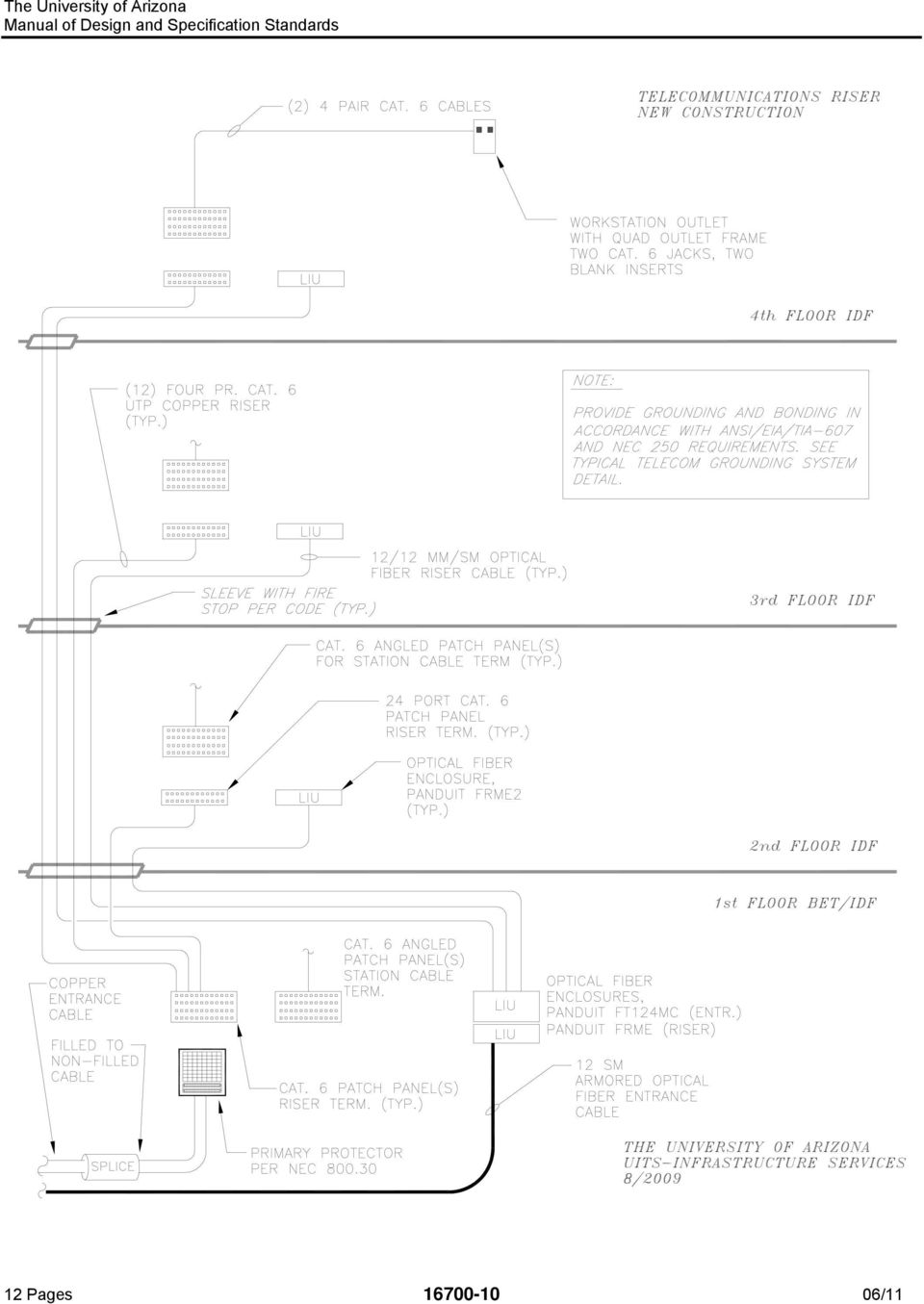
4 Entrance Cabling: Copper entrance cabling shall be PE-39, Type ANMW, ASP, filled, direct burial, #24 AWG solid conductor, with REA color code. Splice cases and/or closures shall be provided for copper entrance cabling as required, with priorapproval by submittal required. Provide transition splice to non-filled cable prior to building entrance termination. Copper entrance cabling shall be provided with station protectors installed in accordance with NEC 800 requirements. Ground entrance cable shield to an approved provable ground as close to the entrance as possible in accordance with NEC requirements. Terminal blocks shall be permanently marked with pair count numbers for entry cable terminations. Optical fiber entrance cables shall be singlemode 8.2/125 Micron, 900 Micron buffered, OS2 rated. Entrance fiber shall be terminated on a rack mount enclosure. In buildings with legacy ST connectors, new connectors shall be ST. In new buildings, or buildings without legacy optical fiber, new connectors shall be LC. Optical fiber cable construction: provide indoor/outdoor riser rated cable for building entrance cables that are run to a splice case within 300 ft. of the building entrance. For backbone cables traversing more than 300 ft. of outside duct and/or tunnel pathway, cable shall be single armor, double jacket. All outside plant optical fiber cables shall be gel-free, with loose tube construction. Minimum strand count for optical fiber entrance cables shall be 12 strands per building. Ground entrance cable shield to an approved provable ground as close to the entrance as possible in accordance with NEC requirements. All optical fiber cable splicing shall be done using the fusion splice method. All optical fiber connectors shall be hot melt type; mechanical ( cam ) type connectors are not acceptable. Riser Cabling: Fiber Optic Riser Cable shall be OFNR or OFNP, tight buffered. Legacy installations: in buildings with existing 62.5 micron cabling, new multimode riser cabling shall be 62.5/125 micron, with minimum guaranteed gigabit Ethernet performance distance of 300m at 850nm and 550m at 1300nm, ST connectors. Singlemode shall be 8.2/125 micron, 900 micron, OS2 rated, with Corning SMF28e glass, with ST connectors. New installations: in buildings without existing legacy optical fiber cabling, new multimode riser cable shall be 50 micron, OM3 rated, with LC connectors. New singlemode riser cable shall be OS2 rated, with LC connectors. All optical fiber connectors shall be hot melt type; mechanical ( cam ) type connectors are not acceptable. Provide a minimum strand count of 12MM/12SM to each telecom room on the riser. Optical fiber riser cables shall be terminated on a rack mounted enclosure, unless specifically noted otherwise on project plans and specifications. Multi-pair copper riser cable shall be shielded, type ARMM, 24AWG, solid conductor, Cat. 3 rated, terminated on 110 blocks. Four pair copper riser cable shall be Cat. 6 rated, as specified for Cat. 6 station cabling, terminated on patch panels. Station Wiring: Provide a quad frame for each outlet, with blank inserts provided for unused openings. HORIZONTAL STATION WIRING MUST BE IN COMPLIANCE WITH EIA/TIA-568B HORIZONTAL WIRING DISTANCE SPECIFICATIONS. The maximum horizontal cable length shall be 90 meters (295 ft). This is the cable length from the mechanical termination of the media in the telecommunications closet to the telecommunications outlet in the work area. The distance maximum includes all wiring that is part of the horizontal wiring. Provide 12 in. of cable slack at each outlet, plus an additional 10 ft. of slack in the telecommunications room, neatly arranged in a loop above (not on) the TTB. 12 Pages /11

5 Station wiring and termination equipment shall be rated Category 6 for all new construction or in existing facilities where the predominant cabling is Category 6. In existing facilities where the predominant cabling is Category 5e or older, Category 5e wiring and termination equipment shall be provided unless specifically noted otherwise in the project plans and/or specifications. Station cable shall be 4 pair, solid conductor, REA color code, plenum rated, UL Listed type CMP w/fep insulation. Cable must comply with EIA/TIA 568B. Outlet jack shall be an eight position modular jack meeting the specifications of FCC Regulations Part All jacks shall be wired according to the T568B wiring schematic. Station cable must not be spliced. Cable runs are to be direct home runs to the IDF and shall not pass through any other station outlet box. The cable bend radius for station cabling shall not be less than four times the outside diameter of the cable. Install cables in conduit, and raceways as specified and supplied and installed by the electrical contractor. All conduits and sleeves shall have insulated bushings installed to protect wire and cables from damage. Installed cables shall not be bundled together. Station cable and wiring shall comply with EIA/TIA 568B, standards. (UTP Category 6 or 5e) Install and terminate fiber optic cable station cabling where specifically indicated in the project plans and/or specifications. Wiring Practices: Station cables shall terminate on a rack mounted patch panel, in a single unified field (no separate voice and data fields). Terminations performed in existing locations without patch panels may utilize 110 style terminations unless the project plans and/or specifications specifically require patch panel installation. Cable and wire above ceiling shall be run parallel or perpendicular to the walls. Diagonal runs will not be accepted. Riser cables shall be run parallel to riser system. Do not install cables in close proximity to fixtures or equipment that may cause RFI or EMI. To reduce the effects of EMI, the following minimum distances shall be adhered to: 5 from power lines of 2kVA or less. 18 from high voltage lighting (including fluorescent). 39 from transformers, motors, and power lines of 5kVA or greater Cables and wire shall not be attached to conduit, pipes, ceiling grid/hanger wire, light fixture hangers, HVAC duct work, etc. All horizontal UTP cable shall be pulled by hand. During pulling operation, an adequate number of workers shall be present to allow cable observation at all points of raceway entry and exit, as well as the point at which cable is payed out from the box or reel, and around corners. Pull cables in accordance with manufacturer's recommendations and ANSI/IEEE C2 Standards. Manufacturer recommendations shall be part of cable submittal. Recommended pulling tensions and bend radius shall not be exceeded. Any cables bent or kinked to radius less than recommended dimensions are not allowed and shall be replaced at no expense to the owner. Cables that show signs of being bent or kinked beyond recommendations then straightened are also not allowed and shall be replaced at no expense to the owner. Cables that show damage to the jacket in any manner shall be replaced at no expense to the owner. Cable and wire above ceiling shall be suspended from approved hangers as required and be routed as close to upper ceiling as practical. Supports shall be installed at a maximum of 3 ft. centers using metal J hooks or other supports meeting or exceeding Category 5e installation requirements. D rings shall not be installed as a means of horizontal cable support Cables shall not be installed in a manner such that they rest upon ceiling tiles, mechanical equipment, and shall not be tie-wrapped to conduit or piping. Raceway Requirements: Conduit fill: In new installations, conduit fill shall not exceed 50%. In retrofit installations, conduit fill may exceed 50% provided that the necessary pulling tension does not exceed the cable rating, and that compression of the cable jacket does not occur. All conduits and sleeves must have UL approved insulated end bushings installed prior to installation of cables or station wire. 12 Pages /11

6 All riser sleeves/conduits and penetrations of fire rated partitions shall be fire stopped using approved methods and materials. All cables shall be installed in compliance with manufacturers pull tension and bend radius specifications. Station cable (voice & data), shall have individual pair twists preserved to point of termination. Cable jacket and inter-pair twists shall be continuous to within ½ of termination. Cables should not be routed in tightly cinched bundles. Avoid over-tensioning or twisting cable during installation. Wall boxes shall be flush mounted, standard metal 4 inch square, deep type, with a single gang plaster ring. Conduit from the wall box shall be concealed and stubbed out above accessible ceiling, to riser closet, or to the telecommunications cable tray. Conduit shall be 1 minimum. Conduit end shall be fitted with a UL approved insulated bushing. Any additional service requirements that will not operate over the standard University building telephone/data wiring shall use a completely separate conduit and wall outlet. Telecommunications Cable Tray Telecommunications cable trays are for the containment and support of telecommunications cables only. Cable trays shall not be used for the support of electrical power cables and conduits. Cable tray shall be bonded to ground in accordance with electrical code requirements. System shall be designed and installed to allow accessibility for adds, moves, and changes. A standard prefabricated ladder type cable tray consisting of solid side panels and side rails connected by individual transverse members, or an approved wire mesh (basket)t type tray shall be used. Ladder type trays shall use standard prefabricated elbows, reducers, crossovers, tees, and elevation change tray sections as required. Trays may be supported by cantilever brackets, trapeze, or individual rod suspension. Supports shall be installed on five foot centers maximum. A support shall be placed within two feet on each side of any connection to a fitting. Center hung supports shall be used only with prior approval from UITS Infrastructure Services Engineering. The inside of the cable tray shall be free of burrs, sharp edges, and projections that can damage cable insulation. A minimum of 12 inch access headroom shall be provided and maintained above the complete cable tray system. Cable trays must have adequate side access for initial cable installation and for future cable adds, moves, and changes. Cable tray tees and 90 s shall have wide radius junctions. Care should be taken to ensure that other building components do not restrict access to the cable tray. Cable tray shall be level and have supports if required to prevent horizontal movement. System shall be designed and installed to allow compliance with EIA/TIA-568B horizontal wiring distance standards. Labeling: All labels shall be machine generated (printer or handheld label machine. All cables shall be permanently identified at both ends. The labeling for outlets shall consist of three components: (1) a unique sequential numeric designation for each jack/cable, (2) an alpha-numeric designation for the telecommunications room serving the outlet, and (3) the final University room number. At the station end, the faceplate of each outlet shall be labeled with the alpha-numeric telecommunications room identifier, plus the sequential numeric jack/cable identifier, as shown on the diagram below. At the telecommunications room end, the patch panel shall be labeled with the final University room number, plus the sequential jack/cable identifier. A label with the sequential jack/cable identifier shall be applied to each end of the station cable within 6 inches of the termination. 12 Pages /11

7 Faceplate Labeling Diagram Fiber optic riser cables shall be labeled utilizing a unique sequential numeric designation for each strand within a given building. Couplers and coupling panels shall be grouped by type of fiber, adjacent to each other either vertically or horizontally depending on LIU construction, with a designation indicating SM for single mode and MM for multimode. Each LIU in an IDF shall be labeled with the unique numeric strand designations, and labeled with the originating end Equipment/BET Room designation (alpha-numeric identifier). The LIU(s) in the Equipment/BET Rooms shall be labeled with the unique numeric strand designations, plus each group of fibers shall be labeled with the remote end IDF Room designation (alpha-numeric identifier). Prior approval of final labeling scheme must be received from UITS Infrastructure Services Engineering. Labels shall be applied at the time of cable acceptance testing. Part 3 - Products Materials List: All items not specifically covered in these specifications must have the concurrence of the University UITS- Infrastructure Services Engineering Department before placement or implementation. Approved Cat. 6 station cables are: Belden 2413, Berk-Tek LanMark1000, Superior Essex DataGain. Cable shall be plenum rated, with violet jacket. Approved Cat. 5e cables (for use only in existing buildings with Cat. 5e or older legacy cabling): Belden 1213, BerkTek LANmark350. Cable shall be plenum rated, with orange jacket. Multi-Pair Copper Riser Termination blocks: Cat. 5e, Panduit #P110B100R2 (rack mount), Panduit #P110BW series (wall mount for legacy applications only) Connecting blocks: Cat.5e: Panduit P110CB4, P110CB5; Cat. 6:Panduit GPCB4 Patch panels for station cabling: angled modular patch panels, Panduit #DPA24688TGY (24 port), Panduit #DPA48688TGY (48 port). Telephone/Data outlets: Cat. 6: Panduit CF1064EI frame, with CMBEI blank modules and CJ688TGVL jacks. All Cat. 6 jacks shall be violet in color. Telephone/Data outlets: Cat. 5e (for use only in existing buildings with Cat. 5e or older legacy jacks): Panduit CF1064EI frame with CMBEI blank modules and CJ5E88TGOR. All Cat. 5e jacks shall be orange in color. Outlet cover plate: all cover plates shall be stainless steel, Pass & Seymour #SS8 (single gang), #SS82 (double gang). 12 Pages /11
.")
8 Wall telephone outlet: Panduit, KWP6P stainless steel phone plate with Giga-TX style CAT 6 keystone jack module Surface mount jack enclosure- use for Blue Light phone jacks, wireless access points: Panduit #CBX2. Blank cover plate: Pass & Seymour #SS14 (single gang), #SS24 (double gang). NOTE: Blank telephone style cover plate shall not be used. Fire Stop sleeves shall be STI EZ-Path, Wiremold FlameStopper, or prior approved equivalent. Caulks and sealants shall be as manufactured by STI, 3M, Nelson, or approved equivalent. Cable shield connector: 3M Scotchlock #4460, 4460-S Bonding & Ground cable/wire: Ground Wire - #6 AWG minimum, Bonding Cable - #6 AWG rated flexible braid with eyelets. Insulated ground wire shall have insulation that is green in color. Splice case filling compound, re-enterable type: 3M Heat Shrink Tubing: Highly Flame Resistant, semi rigid, polyvinylidene fluoride (Kynar). Cable Ties: Plenum type where required by code Panduit hook and loop type. Cross connect wire: Cat. 5e, 2 pair, #24 AWG, solid, copper, REA color code, polyethylene or PVC insulation. Fiber Optic enclosures: All associated hardware shall be provided, including ground clamp, labels, vertical troughs, horizontal troughs, connector panels, blank panels, etc. Fiber Optic Connector: 3M hot melt type. ST type for legacy applications shall be 3M 6100 series (MM), 8100 series (SM). LC type shall be 3M 6600 series (MM), 8600 series (SM). Rack mount optical fiber enclosures for entrance cable applications shall be Panduit #FT124MC with phosphor bronze (multimode) and zirconia ceramic (singlemode) adapter modules. Rack mount optical fiber enclosures for riser cable applications shall be Panduit FRME Series, with phosphor bronze (multimode) and zirconia ceramic (singlemode) adapter panels. Optical fiber riser cable shall be Corning Cable Systems MIC series, Optical Cable Corp. DX series, or Commscope Premises Riser Distribution series. Optical fiber outside plant cable installed in tunnels, duct banks, or aerial construction shall be gel free, Corning Cable Systems Altos Armor series. Optical fiber building entrance cable shall be Corning Cable Systems FREEDM series, gel free with interlocking armor. Surface raceway: Steel or aluminum only. Wiremold 2400 or approved equal is the minimum size acceptable; larger sizes may be required based on the size and number of cable and jacks to be accommodated. D Rings: Lucent 13A (2 in.), 13B (4 inc.), 13C (6 in.) Note: for use in telecom rooms for vertical cable management only. Cable hangers: Caddy Category 5 CableCat J hangers. Approved wire basket type cable trays are Cablofil EZTray and GS Metals Flextray. Cable runway: 12 minimum gray tubular steel, with associated mounting, support, junction, and splice hardware. Chatsworth Products Inc. # or equal. Two post equipment racks: provide 7 ft. x 19 freestanding welded steel equipment rack, B-Line #SB U-TG or approved equal. Vertical cable managers: freestanding equipment racks shall be provided with 7 high, double-sided cable mangers 6 or 10 as indicated on the drawings, Chatsworth MCS Series, or approved equal. Horizontal cable managers shall be provided as shown on the drawings. High capacity cable managers shall be Panduit #NCMHAEF4. Standard size cable managers shall be Panduit #NCMHF1. Small cable managers shall be Panduit #NCMHF1. Blank filler plates for equipment racks shall be Panduit #CPAF1BLY, provided one per freestanding equipment rack as indicated on the drawings. Four post equipment racks shall be 7 ft. high, 19 EIA width, 29 depth, Chatsworth #50120-X03. Equipment rack grounding strips shall be Panduit #RGS134-1Y. ESD ports shall be Panduit #RGESD2-1, with #RGE SDWS wrist strap. Part 4 - Acceptance Testing End-to-end testing of all cable pairs, optical fiber strands, and coax cables shall be performed after completion of installation and termination. UTP Category 6 station wiring shall be in compliance with the 12 Pages /11

9 EIA/TIA 568B standard. Cat. 6 systems shall be tested to Level III accuracy. Labels shall be applied at or before the time acceptance testing is performed. Cable testing shall be performed with the terminating hardware at both ends inserted into the final patch panel, enclosure, or outlet position. For example, testing of fiber strands from the back of the fiber enclosure prior to inserting the connector into the adapter panel mounted in its final resting place is not acceptable. Cable testing shall be performed using Fluke DTX series test equipment. Copper station cable tests shall be Permanent Link tests, performed with the appropriate test adapters/cords. Basic Link and Channel tests are not acceptable. End-to-end attenuation testing of each optical fiber strand shall be made using an optical power meter and optical light source. Multimode fibers shall be tested at 850 and 1300nm. Singlemode fibers shall be tested at 1310 and 1550nm. Attenuation tests shall be performed in both directions. UITS-Infrastructure Services Engineering must approve test documentation. Documentation shall be submitted in Fluke LinkWare Database electronic format. Test result documentation shall indicate the final cable/outlet number assigned to each item tested, as well as identify the project and the telecommunications room serving each item tested. The test result submittal shall be organized by telecommunications room, with the test results in sequential order based on jack id. Test results that are incomplete or that are not organized in sequential order will not be accepted. Part 5 Demolition All abandoned telecommunications cables within a project s boundaries shall be completely removed back to the termination block, including multi-pair cabling, coaxial Ethernet cabling, and station cabling. Tele/data outlets shown on demolition drawings to be removed shall be removed completely including outlet and wiring to the originating IDF termination point. Termination labels shall be revised to reflect all changes. 12 Pages /11

10 12 Pages /11
11 12 Pages /11

12 End of section Pages /11

1.3 Coordinate size and location of telecommunications rooms with the architect to be in compliance with this document and NEC Article 800.
 Section 16700- TELECOMMUNICATIONS Part 1 - General 1.1 The scope of this project includes providing all material and labor to install a complete telecommunication system. The systems shall include riser
Presenters Brett Weiss, Gabe Martinez, Brian Kroeger.
 1 Presenters Brett Weiss, Gabe Martinez, Brian Kroeger. Topics to be covered: Cable identification Purpose of the various cable types Installation techniques Building Infrastructure Overview of networking
Minimum Standards for Data/Voice Infrastructure in New Building Construction
 UNIVERSITY OF WATERLOO Minimum Standards for Data/Voice Infrastructure in New Building Construction 12/17/2012 Offices 1. Two Work Area Outlets (WAO) on opposite walls, each with 2 jacks 2. Each WAO shall
1. Furnish and install faceplate and modular jacks at each single gang outlet as described below:
 Washington University in St. Louis Building: Communication Specification: Research Voice/Network/Typical 1. Furnish and install faceplate and modular jacks at each single gang outlet as described below:
TCTC Cabling Specifications
 TCTC Cabling Specifications Purpose: To provide a standard specification that will be used for all Tri County Technical College (TCTC) facilities requiring structured cabling installation. Product specifications,
DIVISION 27 COMMUNICATIONS. A. System design shall be completed by a Registered Communications Distribution Designer (RCDD).
.") DIVISION 27 COMMUNICATIONS 27 00 00 COMMUNICATIONS A. System design shall be completed by a Registered Communications Distribution Designer (RCDD). B. Comply with American National Standards Institute
DIVISION 27 COMMUNICATIONS 27 00 00 COMMUNICATIONS A. System design shall be completed by a Registered Communications Distribution Designer (RCDD). B. Comply with American National Standards Institute
TELECOMMUNICATIONS STRUCTURED CABLING GUIDELINES AND SPECIFICATIONS. University of Chicago IT Services Infrastructure Services October 2011
 TELECOMMUNICATIONS STRUCTURED CABLING GUIDELINES AND SPECIFICATIONS IT Services Infrastructure Services October 2011 Table of Contents 1 Introduction... 4 1.1 Planning and Design... 4 1.2.1 Roles and Responsibilities...
ATTACHMENT F 050R6800016 - CABLE AND WIRING SERVICES FUNCTIONAL AREA I PRICE PROPOSAL FORM Amendment 6
 050R6800016 CABLE AND WIRING SERVICES (Column A) (Column B) (Column C) (Column D) (Column E) (Column F) (Column G) (B+C+D+E)*F= G Item Description PER 100' RUN PER 150' RUN PER 200' RUN PER 300' RUN QUANTITY
1.1 SYSTEM DESCRIPTION.1 Data system includes data outlets and wiring for office and school applications.
 Issued 2005/06/01 Section 16743 Data System Page 1 of 7 PART 1 GENERAL 1.1 SYSTEM DESCRIPTION.1 Data system includes data outlets and wiring for office and school applications..2 Data system equipment
UT Southwestern Medical Center Information Resources Cable Installation Standard
 UT Southwestern Medical Center Information Resources Cable Installation Standard PART 1- GENERAL 1.01 SUMMARY A. Furnish and install wire, cable, devices, equipment, and accessories for a complete system
UNIFIED FACILITIES GUIDE SPECIFICATIONS
 USACE / NAVFAC / AFCEC / NASA UFGS-27 05 14.00 10 (April 2006) -------------------------------- Preparing Activity: USACE Superseding UFGS-27 05 14.00 10 (April 2004) UNIFIED FACILITIES GUIDE SPECIFICATIONS
1 Campus Cabling Systems Introduction
 1 Campus Cabling Systems Introduction This document represents the campus cable and infrastructure standards adopted and supported by the XXXX. All new construction and renovation should conform to these
SECTION 27 13 24 COMMUNICATIONS OPTICAL FIBER OSP CABLING
 SECTION 27 13 24 COMMUNICATIONS OPTICAL FIBER OSP CABLING PART 1 GENERAL 1.01 DESCRIPTION A. The work covered by this section of the Specifications includes all labor necessary to perform and complete
March 2007. 27 08 00 Commissioning of Communications. See Appendix E3. 27 08 00-1
 March 2007 27 08 00 Commissioning of Communications See Appendix E3. 27 08 00-1 27 11 00 Communications Equipment Room Fittings 1.0 General TELEPHONE RISERS: A. All copper telephone riser cables must be
800 Communications Circuits
 ARTICLE 800 Communications Circuits INTRODUCTION TO ARTICLE 800 COMMUNICATIONS CIRCUITS This article has its roots in telephone technology. Consequently, it addresses telephone and related systems that
Intelligent Cable Management Systems
 Intelligent Cable Management Systems Bringing Practical Application Karen Pearson - Leviton Why Cable Management Matters Performance Cooling and air-handling Maintenance ANSI/TIA 569* Telecommunication
SECTION 28 05 00 COMMON WORK RESULTS FOR ELECTRONIC SAFETY AND SECURITY
 SECTION 28 05 00 PART 1 - GENERAL 1.1 RELATED DOCUMENTS A. Drawings and general provisions of the Contract, including General and Supplementary Conditions and Division 01 Specifications Sections, apply
SECTION 17400 ACCESS CONTROL SYSTEM. CONDITIONS OF THE CONTRACT AND DIVISION 1, as applicable, apply to this Section.
 SECTION 17400 ACCESS CONTROL SYSTEM CONDITIONS OF THE CONTRACT AND DIVISION 1, as applicable, apply to this Section. PART 1 - GENERAL 1.1 RELATED WORK A. 16060 Grounding and Bonding B. 16070 Electrical
SECTION 25110 TELECOMMUNICATION ROOMS
 PART 1 - GENERAL 1.1 SUMMARY A. SCOPE SECTION 25110 TELECOMMUNICATION ROOMS 1. This section includes the minimum installation requirements for equipment and cabling infrastructure in Telecommunication
Specifications for Communication Cabling Distribution Systems
 Washington University in St. Louis Specifications for Communication Cabling Distribution Systems General Overview Listed below are the separate sub-systems of Washington University s structured cabling
All work must conform to the National Electric Code, latest edition, and all other applicable codes and regulations.
 DIVISION 16 ELECTRICAL SECTION 16100 - ELECTRICAL PART 1 - GENERAL SCOPE All electrical work as shown on the drawings and as necessary to provide a complete electrical system. Include primary service,
Building Telecommunications Infrastructure Requirements
 Building Telecommunications Infrastructure Requirements This page identifies specific requirements for the design of telecommunications infrastructure for buildings at Clemson University. (Revised October,
HOUSTON COMMUNITY COLLEGE HCC ALIEF CAMPUS MAIN BUILDING, FIRST, SECOND & FOURTH FLOORS RENOVATION ISSUE DATE: 10.17.12
 SECTION 27 05 26 - GROUNDING AND BONDING FOR COMMUNICATIONS SYSTEMS PART 1 - GENERAL 1.1 SUMMARY A. This Section includes grounding and bonding products, design requirements and installation for communications
Cabling Services (price per pull) Zone 1 Zone 2 Zone 3 Zone 4 Zone 5
 Zone 1 Zone 2 Zone 3 Zone 4 Zone 5") BryComm, LLC -SDD-1901 Cabling Services (per pull) - Labor Only STANDARD TIME The price per cable pull represents all labor to include fishing walls, running cable through modular furniture, terminating,
BryComm, LLC -SDD-1901 Cabling Services (per pull) - Labor Only STANDARD TIME The price per cable pull represents all labor to include fishing walls, running cable through modular furniture, terminating,
DIVISION 26 - ELECTRICAL SECTION 26 05 20 CABLES FOR INSTRUMENTATION
 DIVISION 26 - ELECTRICAL PART 1 - GENERAL 1.01 SUMMARY A. Section Includes 1. Instrumentation Cables 1.02 SUBMITTALS A. Submit in accordance with requirements of Section 01 33 00. B. Product Data: Submit
SYSTIMAX SCS PowerSum and GigaSPEED XL Cabling Installation Guidelines
 SYSTIMAX SCS PowerSum and GigaSPEED XL Cabling Installation Guidelines This document contains critical information regarding the installation of a certified SYSTIMAX SCS that meets or exceeds performance
TIA 569 Standards Update Pathways & Spaces. Ignacio Diaz, RCDD April 25, 2012
 TIA 569 Standards Update Pathways & Spaces Ignacio Diaz, RCDD April 25, 2012 The purpose of this Standard is to standardize specific pathway and space design and construction practices in support of telecommunications
SECTION 16750. TELECOMMUNICATIONS SYSTEM (Cat 6)
") SECTION 16750 TELECOMMUNICATIONS SYSTEM (Cat 6) PART 1 - GENERAL 1.01 REQUIREMENTS A. The general provisions of the Contract, including General and Supplementary Conditions and General Requirements, apply
SECTION 16750 TELECOMMUNICATIONS SYSTEM (Cat 6) PART 1 - GENERAL 1.01 REQUIREMENTS A. The general provisions of the Contract, including General and Supplementary Conditions and General Requirements, apply
SECTION 16750 VOICE AND DATA COMMUNICATION CABLING
 SECTION 16750 VOICE AND DATA COMMUNICATION CABLING PART 1 - GENERAL 1.1 RELATED DOCUMENTS A. Store drawing set and general provisions of the Contract, including General and Supplementary Conditions and
Colorado Army National Guard Grand Junction Readiness Center NGB PN 080204 Coover-Clark & Associates CCA Job No. 0726
 SECTION 260523 - CONTROL-VOLTAGE ELECTRICAL POWER CABLES PART 1 - GENERAL 1.1 SUMMARY A. Section Includes: 1. UTP cabling. 2. RS-232 cabling. 3. RS-485 cabling. 4. Low-voltage control cabling. 5. Control-circuit
BRIDGEWATER COLLEGE HERITAGE HALL RENOVATIONS 12057.00
 SECTION 271500 COMMUNICATIONS HORIZONTAL CABLING PART 1 - GENERAL 1.1 OVERVIEW A. This section provides the necessary guidelines to install service entrance cables to buildings and information for the
Specifying an IT Cabling System
 Specifying an IT Cabling System This guide will help you produce a specification for an IT cabling system that meets your organisation s needs and gives you value for money. You will be able to give your
B. PART 1 - GENERAL of SECTION 271300 BACKBONE COMMUNICATIONS CABLING shall also apply to this section.
 SECTION 271500 - HORIZONTAL UTP CABLING PART 1 - GENERAL 1.1 RELATED DOCUMENTS A. Drawings and general provisions of the Contract, including General and Supplementary Conditions and Division 01 Specification
Data Center. Pre-terminated. Patch Panel System. Cabling Systems Simplified. Patch Panels. 10G + Gigabit. Patch Cords. Plug & Play Installation
 Data Center Pre-terminated Patch Panel System Patch Panels Plug & Play Installation 10G + Gigabit Patch Cords Bundled + Labeled Cabling Systems Simplified Our Mission At Cablesys, our mission is to simplify
Cable Installation Project
 Cable Installation Project 1. Intent. It is the intent of the U.S. Court of Appeals to install Category 6 (CAT6) data cabling in the Robert F. Peckham Federal Building and United States Courthouse, 280
Structured Cabling Statement of Work
 Structured Cabling Statement of Work Multiple Locations June 15, 2010 Page 1 A. GENERAL a. San Joaquin County (referred to as Owner ) is requesting proposals for a new structured cabling infrastructure
ELECTRICAL CONTRACTORS THE UNIVERSITY OF TENNESSEE KNOXVILLE, TENNESSEE SECTION 16050 PAGE 1
 KNOXVILLE, TENNESSEE SECTION 16050 PAGE 1 PART 1 - GENERAL 1.01 RELATED DOCUMENTS: SECTION 16050 A. Drawings and general provisions of Contract, including General and Supplementary Conditions and Division-1
Victor Elementary School District. Technology Infrastructure Standards 02-26-03. Victor Elementary School District
 15579 Eighth Street Victorville, CA 92392 Phone 760. 245-1691 Fax 760.245-6245 www.vesd.net 02-26-03 TABLE OF CONTENTS Introduction 3 Overview of Standards 3 Equipment Specifications 4 Material Specifications
Standards. www.nordx.com 5 ANSI/TIA/EIA-569-A (CSA T530)
") The primary focus of this standard is to provide design specifications and guidance for all building facilities relating to telecommunications cabling systems and components. This standard identifies and
The primary focus of this standard is to provide design specifications and guidance for all building facilities relating to telecommunications cabling systems and components. This standard identifies and
Network Design. Yiannos Mylonas
 Network Design Yiannos Mylonas Physical Topologies There are two parts to the topology definition: the physical topology, which is the actual layout of the wire (media), and the logical topology, which
Reliable, Consistent, Quality
 Reliable, Consistent, Quality 1-877-320-3143 www.fibertronics.com Reliable, Consistent, Quality Welcome To Fibertronics Inc. Reliability, consistency, and quality is what we put behind every Fiber optic
SECTION 27 05 36 CABLE TRAYS FOR COMMUNICATIONS SYSTEMS
 SECTION 27 05 36 CABLE TRAYS FOR COMMUNICATIONS SYSTEMS PART 1 GENERAL 1.01 DESCRIPTION A. The work covered by this section of the Specifications includes all labor necessary to perform and complete such
DENVER PUBLIC SCHOOLS DESIGN AND CONSTRUCTION STANDARDS This Standard is for guidance only. SECTION 17650 SECURITY SYSTEMS
 PART 0 DESIGN STANDARDS 0.01 GENERAL DESIGN GUIDELINES A. Inspections and observations by the Owner do not relieve the A/E of contract responsibilities. B. Chain of command 1. The DPS Project Manager is
Category 6 Solutions. 4. Category 6 Solutions. 09/08 400836IN TrueNet Structured Cabling. Introduction... 4.2. Cable... 4.3. Patch Panels... 4.
 Category 6 Solutions Introduction... 4.2 Cable... 4.3 Patch Panels... 4.4 Modules... 4.6 Patch Cords... 4.12 Outlets... 4.16 Faceplates...4.18 4. 1 Search Category 6 Solutions Introduction ADC KRONE s
The National Armored Cable Manufacturers Association Presents. Installation Standard for Types AC and MC Cables
 The National Armored Cable Manufacturers Association Presents Installation Standard for Types AC and MC Cables An ANSI Standard Original document jointly produced by NECA and NACMA as Standard for Installing
B. Cross-Connect: A facility enabling the termination of cable elements and their interconnection or cross-connection.
 DIVISION 16 ELECTRICAL Section 16740 Telephone System PART 1 - GENERAL 1.1 RELATED DOCUMENTS A. Drawings and general provisions of the Contract, including General and Supplementary Conditions and Division
a. Design or design review of Voice, Data, and Wireless systems b. Copper cable manufacturer selection for new buildings and large scale renovations.
 5.18 Voice and Data Distribution 5.18.1 General Introduction 1. This standards document is to be used for any projects on the University of Calgary campus that involves the voice and data distribution
4 Installation Requirements
 4 Installation Requirements 9 4.1 Code Reference The authority having jurisdiction should be referenced to determine what law, ordinance or code shall apply in the use of flexible duct. Ducts conforming
IT&T Infrastructure Standards
 Technology Services IT&T Infrastructure Standards Version 1.5 17 th April 2015 Page 1 Table of contents 1 CHANGE HISTORY... 3 1.1 DOCUMENT HISTORY... 3 1.2 REVIEWERS... 3 1.3 APPROVALS... 3 2 INTRODUCTION...
Structured Wiring Specifications ERAU Daytona Beach Campus (Dec 14 2011)
") Structured Wiring Specifications ERAU Daytona Beach Campus (Dec 14 2011) A. Objectives The Information Technology (IT) Department of Embry-Riddle Aeronautical University (ERAU) seeks to establish a standards-based
Structured Wiring Specifications ERAU Daytona Beach Campus (Dec 14 2011) A. Objectives The Information Technology (IT) Department of Embry-Riddle Aeronautical University (ERAU) seeks to establish a standards-based
E Series. E Series. Category 6 and 5e. Features
 E Series Category 6 and 5e CommScope, world leader in copper and fiber connectivity, offers the E Series product line as the ideal solution to all your infrastructure needs for safe and reliable data transmission.
Standards and Guidelines for Telecommunications Wiring Design and Installation Montana State University-Bozeman
 Standards and Guidelines for Telecommunications Wiring Design and Installation Montana State University-Bozeman This document defines the standards used for voice and data wiring in buildings used by MSU
Network Telecommunications Design Standards Last Updated June 2013. Youngstown State University
 1 Network Telecommunications & Security Youngstown State University One University Plaza Youngstown, OH 44555 Network Telecommunications Design Standards Last Updated June 2013 Youngstown State University
Division 27 Master Specification for
 Division 27 Master Specification for Information Transport Systems and Spaces May 1, 2014 1 Table of Contents 1 Section 27 10 01 Structured Cabling General Requirements 1.1 Scope 1.2 Approved Contractor
2014 NEC Guide Lines for Home Owner Doing Electrical Work on their Property
 2014 NEC Guide Lines for Home Owner Doing Electrical Work on their Property A brief summary of the most used code references for residential wiring State of Idaho Division of Building Safety Electrical
E-Rate Data Cabling RFP. Addendum 2 ISSUED BY: Alvord Unified School District Information Technology Department
 ALVORD UNIFIED SCHOOL DISTRICT E-Rate Data Cabling RFP Addendum 2 ISSUED BY: Alvord Unified School District Information Technology Department The following are Addendums to the original RFP titled DataCablingRFP.pdf.
SECTION 18370 SIGNAL WIRE AND CABLE
 SECTION 18370 PART 1 - GENERAL 1.01 DESCRIPTION A. Section includes requirements for all cable and wire required for signal and signal power system wiring to wayside shelters, junction boxes, and factory
CORNING CABLE SYSTEMS GENERIC SPECIFICATION FOR TIGHT BUFFER OPTICAL FIBER CABLES FOR INTER- AND INTRABUILDING APPLICATIONS.
 CORNING CABLE SYSTEMS GENERIC SPECIFICATION FOR TIGHT BUFFER OPTICAL FIBER CABLES FOR INTER- AND INTRABUILDING APPLICATIONS September 2006 Revision 7 Corning Cable Systems reserves the right to update
ANSI/TIA/EIA - 568-A, Commercial Building Telecommunications Cabling Standard.
 WIRING STANDARD INTRODUCTION This standard defines a telecommunications wiring system for North Dakota State Agencies, offices or buildings that will support a multi-product environment. The purpose of
ELECTRICAL GUIDELINES FOR SINGLE-FAMILY HOME OWNERS:
 ELECTRICAL GUIDELINES FOR SINGLE-FAMILY HOME OWNERS: Chapter 12 of the Burlington Code of ordinances allows owner occupants of single family homes to do their own wiring if they choose. If you choose to
Electrical for Detached Garages: Updated Feb 19, 2016 for 2015 CE Code in force Jan. 1, 2016. Underground branch circuit feeding a detached garage:
 Electrical for Detached Garages: Updated Feb 19, 2016 for 2015 CE Code in force Jan. 1, 2016 * Garage construction requires permits (electrical, building) * Permits must be applied for at the time. * Dial
NORTH ORANGE COUNTY COMMUNITY COLLEGE DISTRICT SECTION 27 10 00 STRUCTURE CABLING TESTING
 RELATED SECTIONS: NORTH ORANGE COUNTY COMMUNITY COLLEGE DISTRICT Section 27 00 00 General Requirements Section 27 02 00 General Communication Requirements Section 27 05 26 Grounding and Bonding for Communications
How to Estimate the Cost of a Clean Room and Data Center Equipment Electrical Work. Section 2 Types of Methods of Measurements page 4
 How to Estimate the Cost of a Clean Room and Data Center Equipment Electrical Work Table of Contents Section 1 Introduction page 3 Section 2 Types of Methods of Measurements page 4 Section 3 Project Specific
DEPARTMENTAL REGULATION
 U.S. DEPARTMENT OF AGRICULTURE WASHINGTON, D.C. 20250 DEPARTMENTAL REGULATION SUBJECT: Service Center Technology Modernization Project (SCTMP) Wiring/Cabling Specifications for Service Center Agencies
DESIGN GUIDELINES. Local Area Network
 DESIGN GUIDELINES Local Area Network The total oversight and management responsibilities for information assurance (IA) and protection of DoDEA s critical infrastructure fall under the purview of the DoDEA
Developing the Green Data Center
 Products and Solutions to Support Energy Efficiency Ordering Guide Table of Contents Developing the Green Data Center Introduction...5 Airflow Management in the Data Center...6 Angled Panels Glide Cable
TELUS Residential Service Conduit Requirements for Stand Alone Homes and Duplexes in Fibre Only Communities
 1 TELUS Residential Service Conduit Requirements for Stand Alone Homes and Duplexes in Fibre Only Communities Beginning in January 2010 TELUS began designing new subdivisions within the Top 48 population
TELECOMMUNICATIONS DESIGN AND CONSTRUCTION GUIDELINES
 TELECOMMUNICATIONS DESIGN AND CONSTRUCTION GUIDELINES 1.0 General 4 2.0 Distribution System 2.1 Communications Manhole 5 2.1.1 Entrance Duct 5 2.1.2 Ductbank between Manholes 5 2.1.3 Acceptance of Ductbank
University of Houston. Telecommunication Cabling Standards
 University of Houston Information Technology Telecommunication Cabling Standards As prepared by IT Network Operations University of Houston, Telecommunication Cabling Standard - Page 1 Table of Contents
University of North Carolina at Charlotte Design and Construction Manual Section 3, Annex K, 49er Card Systems ANNEX K 49ER CARD SYSTEMS
 ANNEX K 49ER CARD SYSTEMS UNC CHARLOTTE 49ER CARD SYSTEM INSTALLATION AND CONTRACTOR REQUIREMENT SCOPE OF WORK: The following information pertains to the installation and contractor requirements to install
FTE Cabling Best Practices Author: Todd Bill, RCDD/NTS
 FTE Cabling Best Practices Author: Todd Bill, RCDD/NTS Document ID: WP-07-01-ENG Original Issue Date: May 2007 Version: 1.0 FTE Cabling Best Practices 1 Table of Contents Introduction and Applicable Standards...3
SECTION 13850 (28 31 00) FIRE DETECTION AND ALARM SYSTEM
 FIRE DETECTION AND ALARM SYSTEM") SECTION 13850 (28 31 00) FIRE DETECTION AND ALARM SYSTEM ENGINEERING SPECIFICATION INTELLIGENT REPORTING FIRE DETECTION SYSTEM PART 1 GENERAL 1.1 DESCRIPTION A. This specification includes the furnishing,
SECTION 13850 (28 31 00) FIRE DETECTION AND ALARM SYSTEM ENGINEERING SPECIFICATION INTELLIGENT REPORTING FIRE DETECTION SYSTEM PART 1 GENERAL 1.1 DESCRIPTION A. This specification includes the furnishing,
LOS ANGELES CITY COLLEGE Technology Design Standards
 LOS ANGELES CITY COLLEGE Technology Infrastructure Final January, 2007 Prepared for: Los Angeles City College Los Angeles City College TABLE OF CONTENTS Section Page INTRODUCTION 1 DESIGN STANDARDS FOR
TELECOMMUNICATIONS NETWORK STANDARDS AND GUIDELINES FOR THE NEW ADMINISTRATION BULDING
 TELECOMMUNICATIONS NETWORK STANDARDS AND GUIDELINES FOR THE NEW ADMINISTRATION BULDING October 1998 Table of Contents SECTION I: New Construction Programming 1.0 New Construction 1.1 Design Elements..................................
Telecommunications Systems Narrative Page 1 The Engineering Enterprise
 I. TELECOMMUNICATIONS GENERAL REQUIREMENTS A. The project consists of a renovation to the historic Clinical Sciences building, originally built in 1933. The existing building has a total area of 105,000
SECTION 16715 TELECOMMUNICATIONS ACCEPTANCE TESTING
 PART 1 - GENERAL 1.1 SECTION INCLUDES A. Testing Publications and Standards B. Inspection and testing procedures for copper and fiber optic cable, RF CATV / MATV systems, and the antenna systems. C. Documentation
CDGRD-10. Grounding. Solutions For Comm/Data Applications
 CDGRD-10 Grounding Solutions For Comm/Data Applications Overview & Table of Contents Cooper B-Line s Grounding products for rack & runway provide a complete solution for grounding metal supports. The offering
OPEN ITEMS LIST - CONSTRUCTION Project Name: East Central Middle School - Jackson County CLA#: 11003
 OPEN ITEMS LIST - CONSTRUCTION Project Name: East Central Middle School - Jackson County CLA#: 11003 No. Discipline Sent to Name Item Date Noted Date Resolved How item was resolved Electrical Contractor
DESIGN AND INSTALLATION OF RESIDENTIAL FLEXIBLE DUCTWORK SYSTEMS
 DESIGN AND INSTALLATION OF RESIDENTIAL FLEXIBLE DUCTWORK SYSTEMS A. SCOPE 1. This information is intended to assist contractors, installers and code officials in the proper design and installation of flexible
Code Compliance for Spring Steel Fasteners Based on the 2005 NEC
 Code Compliance for Spring Steel Fasteners Based on the 2005 NEC B-Line has recognized the need for a reference source, detailing the National Electrical Code requirements for Spring Steel Fasteners. The
Electrical. This section applies to the design and installation of building power distribution systems.
 Basis of Design This section applies to the design and installation of building power distribution systems. Design Criteria This section contains the architectural, structural and mechanical provisions
CTI TECHNICAL BULLETIN Number 9: A publication of the Cable Tray Institute
 CTI TECHNICAL BULLETIN Number 9: A publication of the Cable Tray Institute Cable Tray Wiring Systems Have Many Cost Advantages Cost is usually a major consideration in the selection of a wiring system.
270526-TC Grounding and Bonding for Telecommunications Systems
 270526-TC Grounding and Bonding for Telecommunications Systems Part 1 - General Related Documents The following related sections of the OT standards shall also be applicable to this section. OT Engineer
Panduit 28 AWG Patch Cords Installation Guideline
 Panduit 28 AWG Installation Guideline Introduction Panduit is a leading supplier of Structured Cabling Systems and Unified Physical Infrastructure. Panduit solutions enable the physical infrastructure
NUIG Campus Network - Structured Cabling System Standards Information s Solutions & Services (ISS)
") NUIG Campus Network - Structured Cabling System Standards Information s Solutions & Services (ISS) Revision date 28 th January 2014 The purpose of this document is to assist Building Refurbishment and
NUIG Campus Network - Structured Cabling System Standards Information s Solutions & Services (ISS) Revision date 28 th January 2014 The purpose of this document is to assist Building Refurbishment and
University of Nevada, Reno Campus Design & Construction Standards
 DIVISION 27: COMMUNICATION 27000 - General Network Standards and Policies The intent of the network policies are: To ensure that computer networking is treated as an essential component of all new and
REQUEST FOR BID AS-NEEDED CABLING SERVICES FOR COUNTY FACILITIES
 REQUEST FOR BID AS-NEEDED CABLING SERVICES FOR COUNTY FACILITIES SECTION 1 REQUIREMENTS AND GUIDELINES INTRODUCTION The County of El Paso ( County ) is issuing this Request for Bid ( Solicitation ) to
CT-02 CABLE TRAY SYSTEMS
 CT-02 CABLE TRAY SYSTEMS SYSTEMS THAT MAKE SENSE Introduction B-Line Systems was formed in 96 and has over 30 years experience manufacturing cable tray systems in which it has grown to become the industry
SECTION 08360 SECTIONAL OVERHEAD DOORS 521 SERIES ALUMINUM SECTIONAL OVERHEAD DOORS
 SECTION 08360 SECTIONAL OVERHEAD DOORS 521 SERIES ALUMINUM SECTIONAL OVERHEAD DOORS Display hidden notes to specifier by using Tools / Options / View / Hidden Text. On newer versions of Microsoft Word
PUBLIC RESTROOMS, DESIGN INTENT
 PUBLIC RESTROOMS, DESIGN INTENT 1.01 STRUCTURAL A. Where feasible, metal stud partitions will be constructed on a 6 high concrete curb. 1.02 MECHANICAL A. Restrooms will have a minimum of 15 air changes
INSTALLATION GUIDELINES for SOLAR PHOTOVOLTAIC SYSTEMS 1
 City of Cotati Building Division 201 W. Sierra Ave. Cotati, CA 94931 707 665-3637 Fax 792-4604 INSTALLATION GUIDELINES for SOLAR PHOTOVOLTAIC SYSTEMS 1 Any PV system on a new structures should be included
ANSI/TIA-942 Telecommunications Infrastructure Standards for Data Centers
 ANSI/TIA-942 Telecommunications Infrastructure Standards for Data Centers Jonathan Jew jew@j-and and-m.com J&M Consultants, Inc Co-chair TIA TR-42.1.1 data center committee Co-chair BICSI data centers
BIX Cross-Connect System Distribution Connectors, Multiplying Connectors and Modular Jack Connectors
 C O M M E R C I A L N E T W O R K I N G C O P P E R 15.13 Distribution Connectors, Multiplying Connectors and Modular Jack Connectors A0393146 QCBIX1A4 Connector BIX Distribution Connector The BIX Distribution
SECTION 08332 COILING COUNTER DOORS. Display hidden notes to specifier. (Don't know how? Click Here)
") SECTION 08332 COILING COUNTER DOORS Display hidden notes to specifier. (Don't know how? Click Here) PART 1 GENERAL 1.1 SECTION INCLUDES A. Coiling Metal Counter Doors. B. Coiling Counter Fire Doors. 1.2
SECTION 08332 COILING COUNTER DOORS Display hidden notes to specifier. (Don't know how? Click Here) PART 1 GENERAL 1.1 SECTION INCLUDES A. Coiling Metal Counter Doors. B. Coiling Counter Fire Doors. 1.2
ANSI/TIA-942 Telecommunications Infrastructure Standard for Data Centers
 ANSI/TIA-942 Telecommunications Infrastructure Standard for Data Centers Jonathan Jew jew@j-and-m.com J&M Consultants, Inc Co-chair TIA TR-42.1.1 data center working group Co-chair BICSI data centers standards
Request for Proposal DESIGN AND INSTALLATION OF STRUCTURED COMMUNICATIONS CABLE SYSTEMS. Kalispell Public Schools
 Request for Proposal DESIGN AND INSTALLATION OF STRUCTURED COMMUNICATIONS CABLE SYSTEMS For Kalispell Public Schools 2015 TABLE OF CONTENTS I. PROJECT DESCRIPTION / GENERAL SCOPE OF WORK...3 II. PROJECT
Unarmored Variable Frequency Drive (VFD) Cable Termination Guide
 Cable Termination Guide") Authorized Distributor Unarmored Variable Frequency Drive (VFD) Cable Termination Guide Be Certain with Belden A Step-by-Step Look at the Connection/Termination of Unarmored VFD Cables Terminating Unarmored
Authorized Distributor Unarmored Variable Frequency Drive (VFD) Cable Termination Guide Be Certain with Belden A Step-by-Step Look at the Connection/Termination of Unarmored VFD Cables Terminating Unarmored
B. Related Sections: 1. Section 26 05 33 - Raceway and Boxes for Electrical Systems.
 SECTION 262726 - WIRING DEVICES PART 1 - GENERAL 1.1 SUMMARY A. Section includes wall switches; wall dimmers; receptacles; multioutlet assembly; and device plates and decorative box covers. B. Related
Terminating 25-Pair Cable and 4-Pair Cross Connects
 Terminating 25-Pair Cable and 4-Pair Cross Connects Estimated Time: 90 minutes Number of Teams: 2 Number of Team Members: one to four This Lab has four major parts that will be addressed separately. 1.
26 0533 Raceway and Boxes for Electrical Systems Page 1 of 7
 Last Update: November, 2015 A. Conduits: Consultant s Handbook Page 1 of 7 1. All conductors for each and every electrical system shall be installed in a raceway except communications and A/V systems which